

Page 1
Veerrssiioonn
V
Setup and Assembly Manual
R11
R
This device is compliant.
Page 2

File: BE3-R1-SetupAndAssembly-H.doc
Page 3

Introduction
Dear Customer,
We congratulate you on the acquisition of this innovative product from Image Access.
We at Image Access are proud of the work we do; it is the result of our extremely high
standards of production and stringent quality control.
With the Bookeye® 3, Image Access offers an efficient Planetary Scanner which covers a
wide scope of applications due to its versatility. Its integrated web based user interface
makes all functions available in structured menus.
For this reason, we ask you to read all manuals of the Bookeye® 3 attentively before
starting to work with it. By doing so, you will avoid risks to the user, operation errors and
you can control all functions from the beginning.
In addition please consider the following points:
• Damages to your unit may have occurred during shipping. Please check for
damages immediately after delivery of the unit. Inform your supplier if damage has
occurred.
• Read and ensure that you understand the safety notes. They were developed for
your protection and safety as well as to protect the unit.
• Regular maintenance conserves the high quality and safety of the Bookeye® 3
during the entire service life.
If you have any further questions, please feel free to contact your local dealer or
Image Access directly. Our staff will be happy to help you.
We wish you success and complete satisfaction with your daily work with the
Bookeye® 3.
Regards
Your Image Access Team
Setup and Assembly Manual Page 3
Page 4

About this Manual
Setup and Assembly Manual
This Setup and Assembly Manual has been written for users and technical staff with
some basic mechanical as well as software skills. Many resellers will offer on-site
installation, therefore, some parts of the manual might be of minor interest to the reader.
Nevertheless, Section B and Section C must be carefully read to guarantee maximum
performance and quality of the product.
The access level at which these setup and adjustment processes are performed is called
“Poweruser”. This “Poweruser” level is password protected from access by the normal
operator.
All manuals can be downloaded from our customer service portal at
http://service.imageaccess.de
manuals.
This manual is divided into four sections, A to D.
Section A describes the hardware of the device. It includes unpacking and
mechanical installation. These instructions must be followed carefully to
ensure proper functionality, best possible quality, and performance of the
device. This device is a precise optical instrument and should be handled
accordingly.
. Be sure to always check for the latest versions of these
Section B describes the software setup. It includes the optical adjustments necessary
after the setup. The section also describes the option installation
procedure.
Section C describes troubleshooting procedures and test scan generation.
Section D shows all technical data and necessary declarations.
Printed in Germany. All rights reserved.
Reproduction in whole or in part in any form or medium without express written permission of Image
Access is prohibited.
Scan2Net® is a registered trademark of Image Access. All other designated brands herein are trademarks of Image Access.
All other trademarks are the property of their respective owners.
Image Access reserves the right to change the described products, the specifications or documents at
every time without prior notice. For the most recent version, always check our web site
www.imageaccess.de
© 2008 – 2009 by Image Access GmbH, Wuppertal, Germany.
or the customer service portal at http://service.imageaccess.de
Page 4 Setup and Assembly Manual
Page 5

A
Version History
Version Published in Content/Changes/Supplements
A November 2005 Preliminary version.
Description of the device elements.
Description of assembling steps.
B January 2006 Preliminary version.
Some changes at the body element base. Order of assembling steps
for the camera neck and camera head has been changed.
C February 2006 Preliminary version.
Chapter added: Scan2Net Firmware Adjustment Procedure.
D February 2006 Preliminary version.
Additional information in chapter Final Mechanical Adjustments.
New: Recovery Function
E April 2006 First Final Edition.
General formatting and several technical changes.
F August 2006
G November 2006 Second Edition: Additional information concerning measurement of
H January 2009
Second Edition: Chapter A.1.2 added.
Chassis A and B introduced. Chapter B2 changed.
dditional information concerning adjustment of the lamps, see
chapter A.2.4.1 to A.2.4.4.
Auto Focus, chapter B.2.2. to B.2.2.2. Differentiation between
Chassis A and Chassis B.
New chassis version.
List of assembling material revised.
Additional information in chapter B.2 Mandatory Optical Adjustments
Renew of some screenshots of the user interface because of new
firmware version.
NOTE:
This equipment has been tested and found to comply with the limits for a class A digital device, pursuant to
Part 15 of the FCC rules. These limits are designed to provide reasonable protection against harmful
interference when the equipment is operated in a commercial environment. This equipment generates,
uses, and radiate radio frequency energy and, if not installed and used in accordance with the operation
manual, may cause harmful interference to radio communications.
Operation of these equipment in a residential area is likely to cause harmful interference in which case the
user will be required to correct the interference at his own expense.
Setup and Assembly Manual Page 5
Page 6

Table of Contents
A Hardware Setup--------------------------------------------------------------12
A.1 Content on Delivery ................................................................................. 12
A.1.1 Tools and Assembling Material 15
A.1.2 Device Location 16
A.1.2.1 Environment 16
A.1.2.2 Ambient Light 16
A.1.2.3 Scanner Table 17
A.1.2.4 Power outlet 17
A.2 Assembling the Components ................................................................... 18
A.2.1 Assembling the Camera Head to the Neck 18
A.2.2 Assembling Lamps and Camera to the Body Element 21
A.2.3 Assembling the Glass Plate 28
A.2.4 Setting the Initial Lamp Position 33
A.2.4.1 Performing the mechanical adjustment of the lamps 34
A.2.4.2 Saving the lamp positions 37
A.2.4.3 Leaving the initialization mode without saving 37
A.2.4.4 Lamp position control mode 38
Page 6 Setup and Assembly Manual
Page 7

Table of Contents, part 2
B Software Setup--------------------------------------------------------------- 39
B.1 Setup Network IP Address........................................................................39
B.2 Mandatory Optical Adjustments ................................................................42
B.2.1 Scan Start 45
B.2.2 Auto Focus 47
B.2.2.1 Auto Focus Measurement with Glass Plate Opened 48
B.2.2.2 Auto Focus Measurement with Glass Plate Closed 50
B.2.3 Scan Center 52
B.2.4 White Balance 53
B.2.4.1 Some Basic Information 53
B.2.4.2 White Balance with Glass Plate opened 55
B.2.4.3 White Balance with Glass Plate closed 57
B.2.5 Laser Check 58
B.3 Options and Settings ................................................................................60
B.3.1 Time Server 60
B.3.2 Sound Control 61
B.3.3 Firmware Update 62
B.3.4 Install Options 63
B.3.5 Install ICC Profiles 64
Setup and Assembly Manual Page 7
Page 8

Table of Contents, part 3
C Tests and Troubleshooting ---------------------------------------------- 65
C.1 Network Performance Test ...................................................................... 65
C.2 Scan Test Targets.................................................................................... 67
C.2.1 Scan CSTT Test Target 67
C.2.2 Scan IT8 Test Target 68
C.3 Recovery Function................................................................................... 69
C.3.1 Important Notes before recovering to Factory Defaults 69
C.3.2 How to Recover to Factory Defaults 69
C.4 Troubleshooting Matrix ............................................................................ 71
C.5 Error Codes ............................................................................................. 73
D Technical Data---------------------------------------------------------------- 76
D.1 Scanner Specifications ............................................................................ 76
D.2 Ambient Conditions.................................................................................. 76
D.3 Electrical Specifications ........................................................................... 77
D.4 Dimensions and Weight ........................................................................... 78
Page 8 Setup and Assembly Manual
Page 9

Table of Pictures
Picture 1: Transport box ....................................................................................................12
Picture 2: Cardboard separator with lamps and neck........................................................13
Picture 3: Reference folder removed .................................................................................13
Picture 4: Scanner main body and camera head box........................................................14
Picture 5: Camera head in cardboard box ......................................................................... 14
Picture 6: Attaching camera neck to camera head ............................................................18
Picture 7: Check the alignment … .....................................................................................19
Picture 8: ... at both sides ..................................................................................................19
Picture 9: Fastening at position A......................................................................................19
Picture 10: Fastening at position B....................................................................................19
Picture 11: Camera neck assembled at camera head.......................................................20
Picture 12: Placing the cover on the neck .........................................................................20
Picture 13: Cover in final position ......................................................................................20
Picture 14: Fastening the screws.......................................................................................20
Picture 15: Two persons(!) lift the device out of the transport box.....................................21
Picture 16: Removing the transport screws .......................................................................22
Picture 17: Removing the countersunk socket screw ........................................................22
Picture 18: Remove marked screws ..................................................................................23
Picture 19: Body element cover opened............................................................................23
Picture 20: Position of gas spring fixture at right lamp.......................................................24
Picture 21: Fixing the lamp ................................................................................................24
Picture 22: Camera neck assembly ................................................................................... 25
Picture 23: Front side.........................................................................................................25
Picture 24: Back side.........................................................................................................25
Picture 25: Connector board with camera neck cables .....................................................26
Picture 26: Connector of flat ribbon cable..........................................................................26
Picture 27: Cable loop .......................................................................................................26
Picture 28: Keyboard cable while moving the body cover .................................................27
Picture 29: Body cover at edge of power supply ...............................................................27
Picture 30: Book cradle controller......................................................................................28
Picture 31: Bearing in the center of the glass plate ...........................................................28
Picture 32: T-slot nut in corresponding position.................................................................29
Picture 33: Hinge mounted at right lamp ...........................................................................29
Picture 34: Position of locking springs ...............................................................................30
Picture 35: Removing the locking spring ...........................................................................30
Picture 36: Gas spring mounted to glass plate..................................................................31
Picture 37: Locking spring inserted....................................................................................31
Picture 38: Locking spring locked ......................................................................................31
Picture 39: Gas spring completely mounted ......................................................................32
Picture 40: Press the keys simultaneously ........................................................................34
Setup and Assembly Manual Page 9
Page 10

Table of Pictures, part 2
Picture 41: Lamps in start position .................................................................................... 35
Picture 42: Up/down key on right side of keyboard ........................................................... 35
Picture 43: Light beam on right side of the book cradle .................................................... 36
Picture 44: Light beam adjusted........................................................................................ 37
Picture 45: Start screen..................................................................................................... 39
Picture 46: Login level screen ........................................................................................... 40
Picture 47: Poweruser Main Menu screen ........................................................................ 40
Picture 48: Network configuration screen.......................................................................... 41
Picture 49: Scan2Net Start screen .................................................................................... 43
Picture 50: Buttons for login levels .................................................................................... 43
Picture 51: Poweruser Main Menu screen ........................................................................ 44
Picture 52: Adjustment & Support screen ......................................................................... 44
Picture 53: Scan Start adjust screen ................................................................................. 45
Picture 54: Scan Start results............................................................................................ 46
Picture 55: Available glass plate positions ........................................................................ 47
Picture 56: Auto Focus measurement with open glass plate ............................................ 48
Picture 57: Auto Focus results .......................................................................................... 49
Picture 58: Information about book cradles position ......................................................... 50
Picture 59: Auto focus measurement screen .................................................................... 51
Picture 60: Scan Center screen ........................................................................................ 52
Picture 61: Brightness Correction Factor screen............................................................... 54
Picture 62: R G B controls................................................................................................. 54
Picture 63: Glass plate positions for white balance........................................................... 55
Picture 64: White Balance screen, glass plate opened ..................................................... 56
Picture 65: White Balance screen, glass plate closed....................................................... 57
Picture 66: Laser Check screen ........................................................................................ 58
Picture 67: Laser check result ........................................................................................... 59
Picture 68: Adjust Time & Date screen ............................................................................. 60
Picture 69: S2N Sound System screen ............................................................................. 61
Picture 70: Link Sounds to Events screen......................................................................... 61
Picture 71: Update Scanner firmware screen.................................................................... 62
Picture 72: Install Option screen .......................................................................................63
Picture 73: ICC Profile screen ........................................................................................... 64
Picture 74: Perform Speed Test screen ............................................................................ 65
Picture 75: Network Analyzer Parameters screen............................................................. 66
Picture 76: Network Analyzer Result screen ..................................................................... 66
Picture 77: Scan Test Target screen................................................................................. 67
Picture 78: CSTT Test Target screen................................................................................ 67
Picture 79: Scan Test Target screen................................................................................. 68
Picture 80: IT8 Test Target screen.................................................................................... 68
Picture 81: Connectors on rear panel................................................................................ 69
Page 10 Setup and Assembly Manual
Page 11

Setup and Assembly Manual Page 11
Page 12
A Hardware Setup
A.1 Content on Delivery
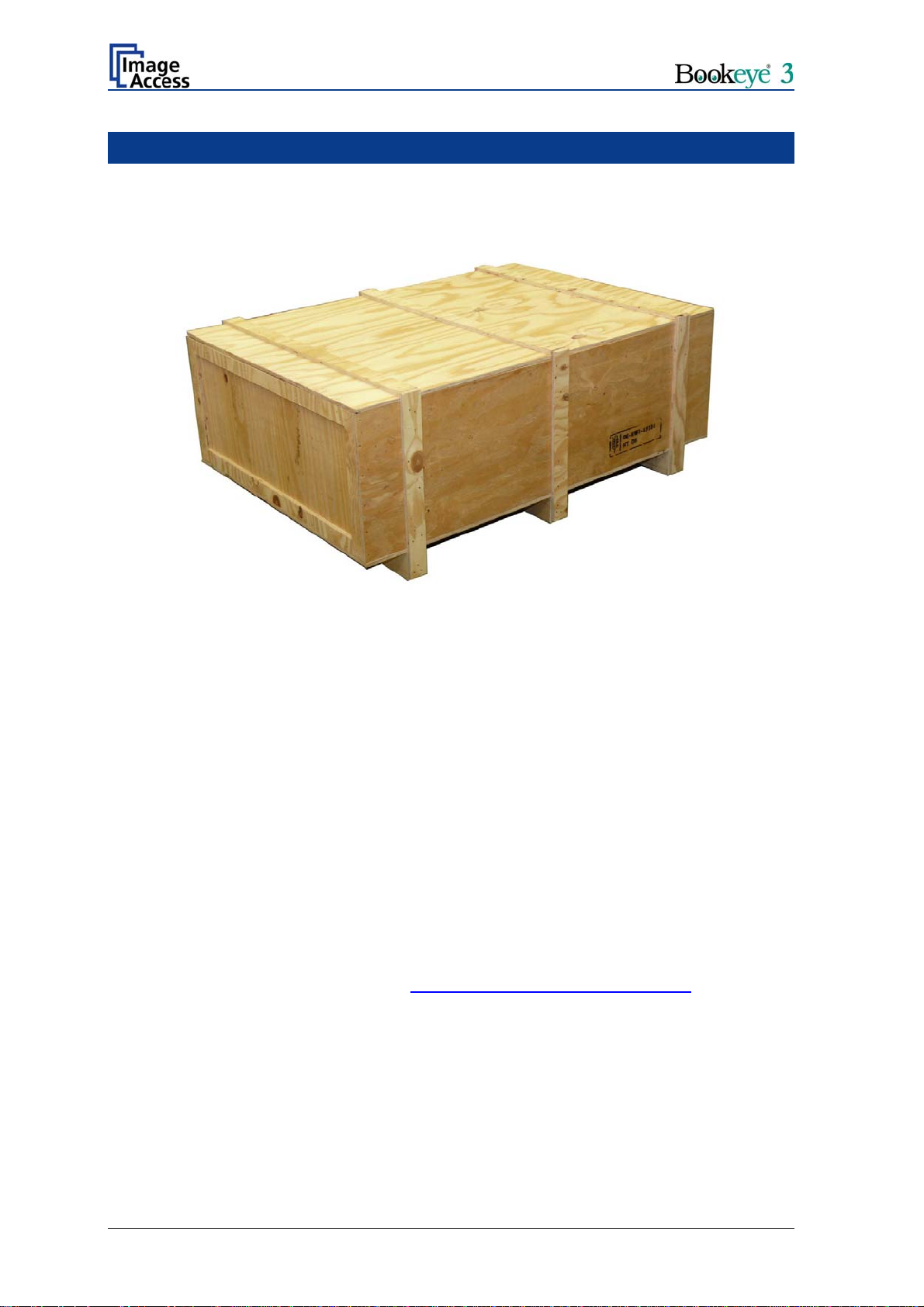
The Bookeye® 3 scanner is delivered in a wooden transport box.
Picture 1: Transport box
The transport box contains all components of the scanner. These are
• the two lamps,
• the camera neck,
• the glass plate,
• a cardboard box containing the camera head and the integrated short part of the
camera neck,
• the accessory boxes and
• the reference folder with some test targets.
Please note: Keep the wooden transport box and the cardboard box for future use!
For warranty returns, the scanner must be sent back in the original
transport box to avoid transport damages.
The crates and the inserts have been designed and tested to withstand all impacts, in
accordance with the internationally recognized test procedure ISTA-1B for packages over
150lbs or 68kg. Details can be found at http://www.ista.org/Testing/Tests.htm
This requires that the packaging instructions are followed precisely. One common mistake
made is that additional parts are put in the side pockets formed between the crate and the
PE- inserts. This space must be free of obstacles in any case; because in the case of an
impact, the inserts will compress to 40% of their original size and the free space will be
used up completely.
.
Page 12 Setup and Assembly Manual
Page 13
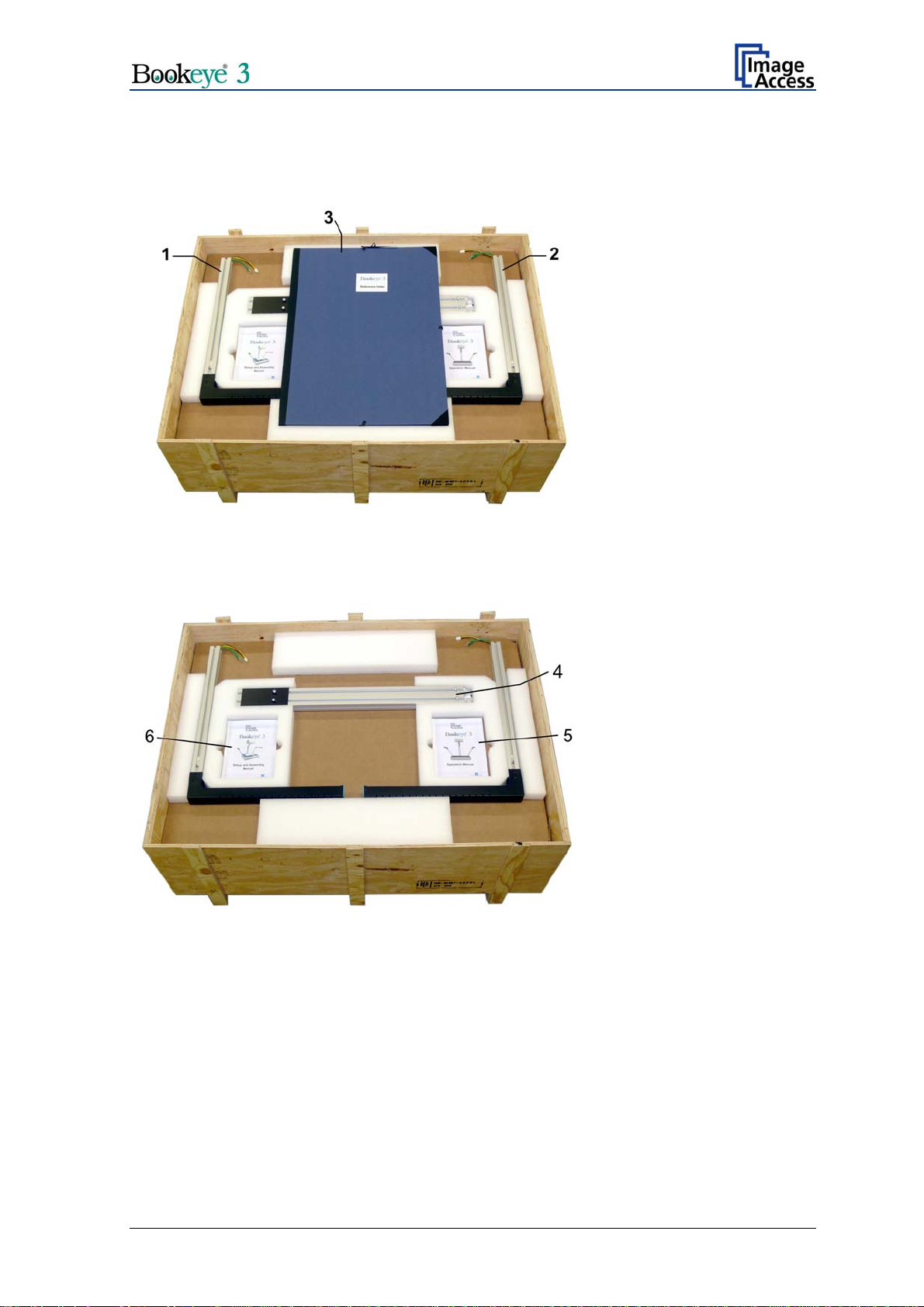
On the cardboard separator are placed two lamps, the reference folder, the camera neck
below the reference folder, and two manuals. All parts are held in position by foam rubber
elements.
Lamps: (1) and (2)
Reference folder: (3)
Picture 2: Cardboard separator with lamps and neck
Picture 3: Reference folder removed
Camera neck: (4)
Manuals: (5) and (6)
Setup and Assembly Manual Page 13
Page 14
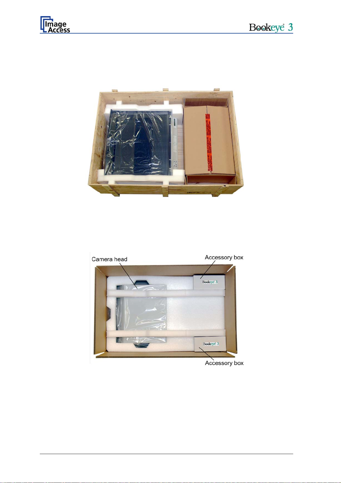
Remove the cardboard separator. Now the scanner’s main body and the cardboard box
with the camera head are visible.
The main body is wrapped into a protection foil and is hold with two foam rubber elements
in its position.
Picture 4: Scanner main body and camera head box
Two book cradle plates are attached to the scanner’s main body.
Take the cardboard box out of the transport box. The cardboard box contains the camera
head and the short part of the camera neck. The short part of the camera neck is attached
to the camera head.
Picture 5: Camera head in cardboard box
In addition to the camera head, the transport box also contains two accessory boxes.
Page 14 Setup and Assembly Manual
Page 15

A.1.1 Tools and Assembling Material
The accessory boxes contain the assembly materials and some tools.
Tools:
1x Allen wrench with ball shaped head, size 6 mm
1x Allen wrench, size 4 mm
1x Allen wrench, size 3 mm
1x Allen wrench, size 2.5 mm
Assembling material:
6x Allen screws, M4x10. Used to fix the cover of the scanner to the scanner’s body.
8x Allen screws, M8x12, with plastic washers. Used to fix the lamps (4x) to the scanner
housing, to fix the hinges to the lamps (2x), and to fix the green cover (2x).
2x Allen screws, M8x14; with metal washers. Used to fix camera head and camera neck.
10x Allen set screws, M8x8. Used to fix the camera neck at the scanner’s body (8x) and to
fix the neck to the camera head (2x).
4x Lens head Allen screws, M4x10. Used to fix the cover of the scanner to the scanner’s
body.
2x Hinges
2x Gas springs for the glass plate
A Recovery key
A network cable, a cross-over cable, and a power cable.
Micro fiber cleaning cloth for the book cradle and other surfaces.
Please note: Keep the transport boxes for future use! For warranty returns, the scanner
must be sent back in the original transport box to avoid transport
damages.
In the camera neck, four T-slot nuts are inserted.
Two T-slot nuts are used as counterparts to the screws which fix the camera head to the
camera neck. The two T-slot nuts on the rear side are used as counterparts to the screws
which fix the cover between camera head and neck.
Setup and Assembly Manual Page 15
Page 16

A.1.2 Device Location
A.1.2.1 Environment
Choose a location that complies with the limits of temperature and humidity. Refer to
chapter D.2 for detailed environmental specification.
A.1.2.2 Ambient Light
The location should have a controlled ambient light situation. Light scenarios to avoid are
direct sunlight, spot light from light beams, light sources that cause sharp shadows on the
scanning bed, high levels of ambient light and varying light conditions.
The Bookeye® 3 scanner is an open system with a built-in high quality light source. Open
system means, that the ambient light is added to the light seen by the camera.
The recommended location for the Bookeye® 3 scanner:
• Is not exposed to daylight.
• Is evenly illuminated from the ceiling with fluorescent lamps with electronic
ballasts. The light intensity measured on the book cradles should be 300 lux or
less.
• The light should not cause any shadows; therefore the variation of the intensity
across the scan area should be kept below 20%.
If the fluorescent lamps are powered by non electronic ballasts, they will produce a flicker
twice the frequency of the main power supply (100Hz or 120Hz). If the intensity of this
light becomes too high, vertical stripes of even distances of approx. 8-12 pixels will be
visible on the scan.
Direct sunlight will vary over the day and will result in overexposed images. Sunlight also
can produce sharp shadows.
Light beams from spot lights will also produce sharp shadows. They emit (in most cases)
a high level of infrared light. Infrared light is not visible to the human eye but not the
camera. The light source of the Bookeye® 3 scanner itself has no infrared content at all.
The advantage is that the scanner does not have an image quality degrading infrared
filter. Too much infrared content will result in overexposure.
The Bookeye® 3 scanner has an integrated “White Balance” function. This function will
compensate the ambient light influences. Therefore it is recommended to perform the
“White Balance” function when the ambient light scenario has been changed.
Page 16 Setup and Assembly Manual
Page 17

A.1.2.3 Scanner Table
Place the device on a flat and solid base, preferable a solid table.
Please note: The load bearing capacity of the table must correspond to the device
weight. The table should be build to hold at least three times the weight of
the unit.
Also it should not shake or move to avoid image distortions. If the table is too weak it can
be attached to a solid wall to stabilize it.
A.1.2.4 Power outlet
Ensure that the power outlet is always accessible when the scanner
is placed at its working position.
This will help to separate the device from the power outlet in case of an emergency.
Setup and Assembly Manual Page 17
Page 18
A.2 Assembling the Components
A.2.1 Assembling the Camera Head to the Neck
Take the camera head out of its transport box and place it on a suitable table.
Note: For the following steps, the camera head must be placed with the top side down
on the table.
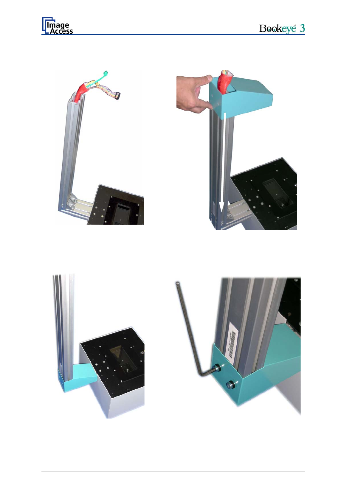
The cables coming out of the camera head must be inserted into the neck and must be
guided through it.
One end of the neck and the end of the camera head element are cut at a corresponding
angle.
Insert the cables at this end of the neck and push them forward carefully. The cables are
protected by a flexible foam material tube.
Picture 6: Attaching camera neck to camera head
When the cables have been pushed through the upper side of the neck, position the neck
over the fastening angles.
Page 18 Setup and Assembly Manual
Page 19
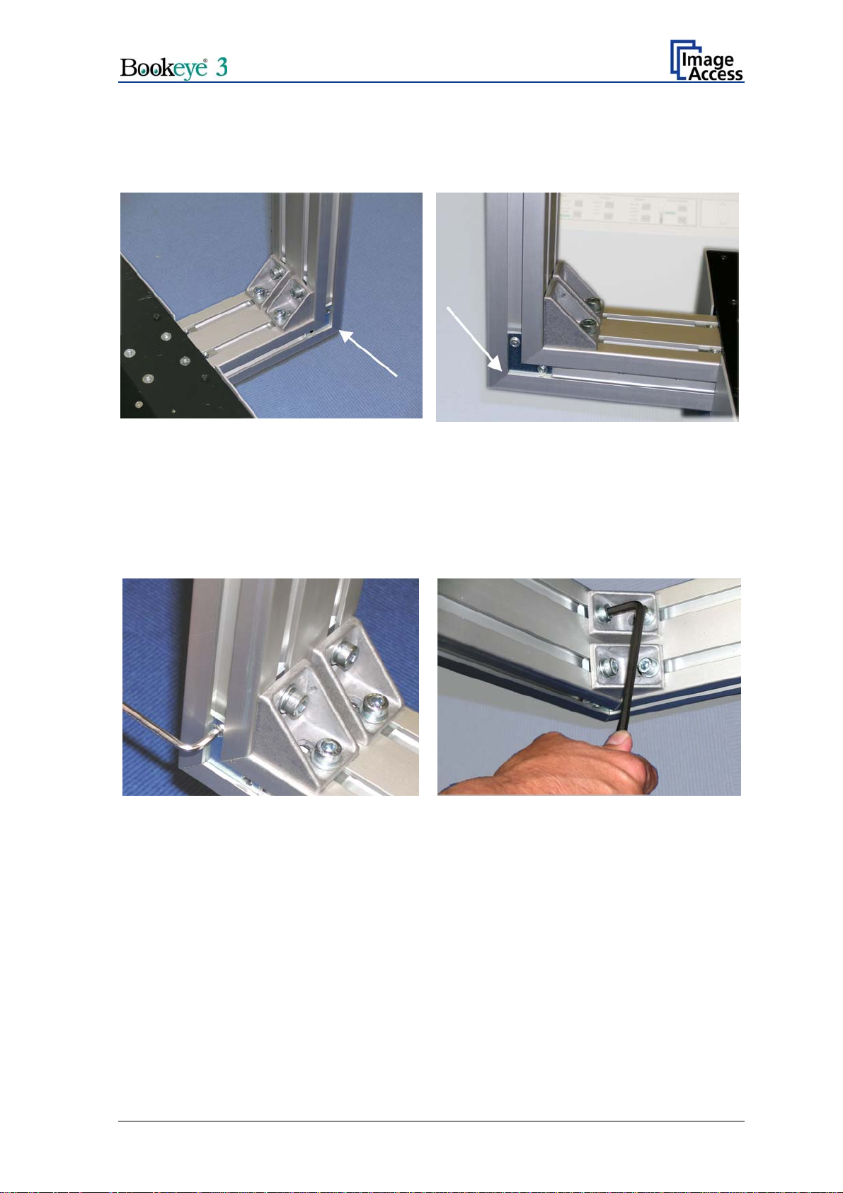
Place the T-slot nuts in the neck corresponding to the fastening brackets before fastening.
Before fastening the screws, check the alignment of the two neck elements to each other.
There must not be a gap between the two neck elements.
Picture 7: Check the alignment …
Picture 8: ... at both sides
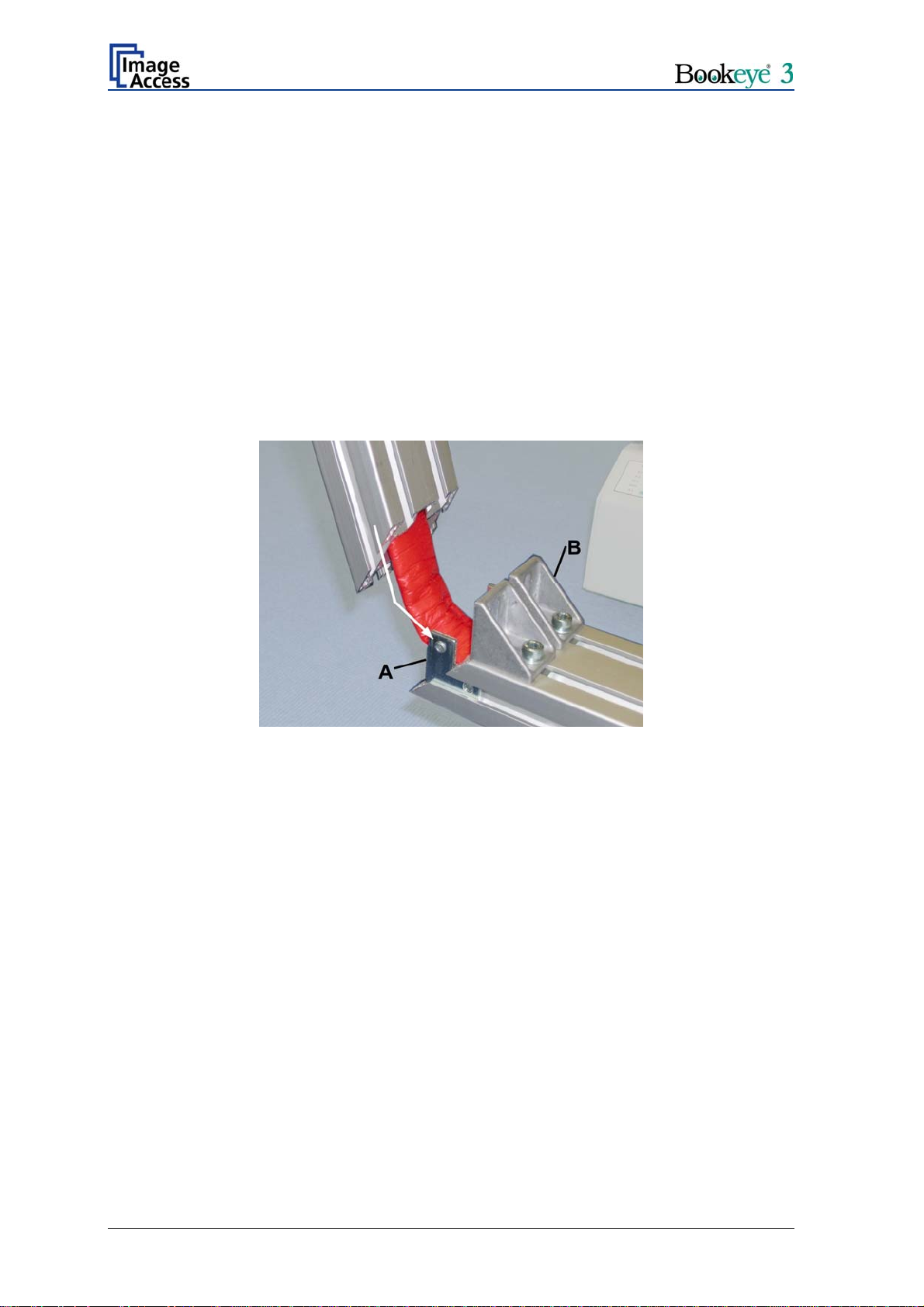
To ensure a proper angle alignment between the short neck and the long neck it is
necessary to fasten the screws in the given order.
At first fasten the two Allen set screws M8x8 in the fastening angle at position A.
Then continue with the two Allen screws M8x14, using a metal washer at each screw, in
the fastening brackets (B).
Picture 9: Fastening at position A Picture 10: Fastening at position B
Setup and Assembly Manual Page 19
Page 20
Picture 11 shows both components fully assembled. Finally, place the green cover on the
neck as shown below in the following pictures.
Î
Picture 11: Camera neck assembled
at camera head
Fasten the cover with two Allen screws M8x12. Use plastic washers with the screws.
Picture 12: Placing the cover on the neck
Î
Picture 13: Cover in final position
Page 20 Setup and Assembly Manual
Picture 14: Fastening the screws
Page 21
A.2.2 Assembling Lamps and Camera to the Body Element
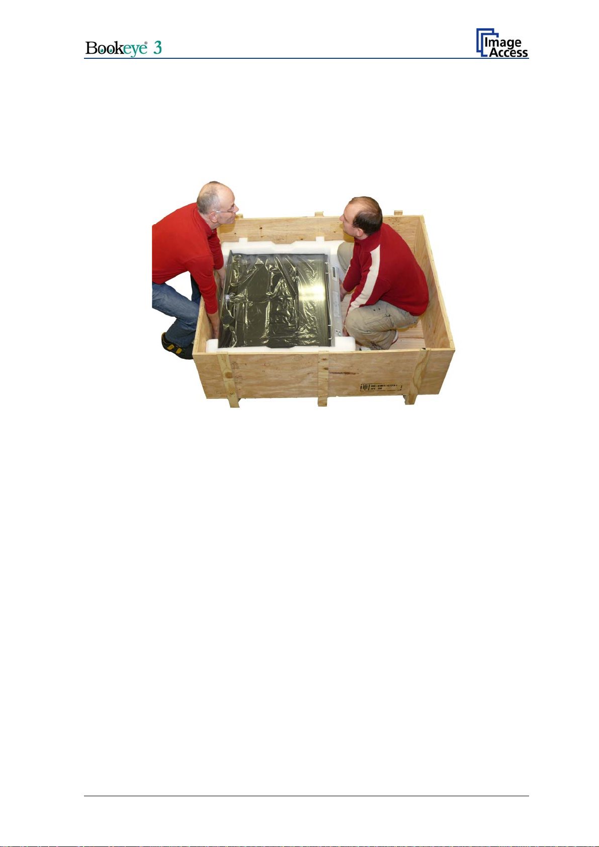
Take the body element out of the transport box.
Note: Because of the device weight, lifting the body element out of the transport box
must be done by two persons.
Picture 15: Two persons(!) lift the device out of the transport box
Place it on a suitable stable surface. The bearing capacity of the table must exceed the
total weight of the scanner.
Before continuing with the next steps, remove the foam rubber elements and the
protection foil.
Setup and Assembly Manual Page 21
Page 22
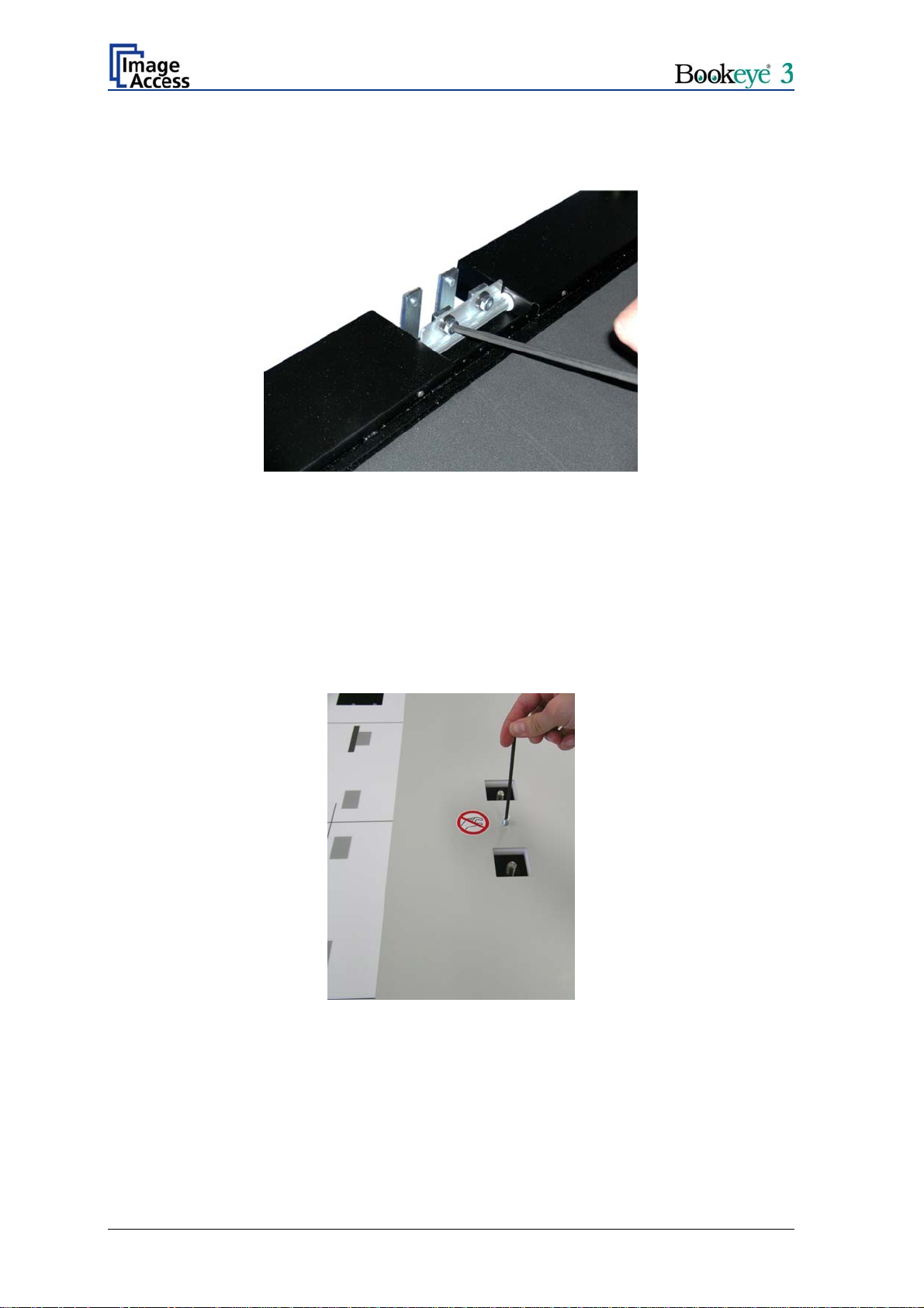
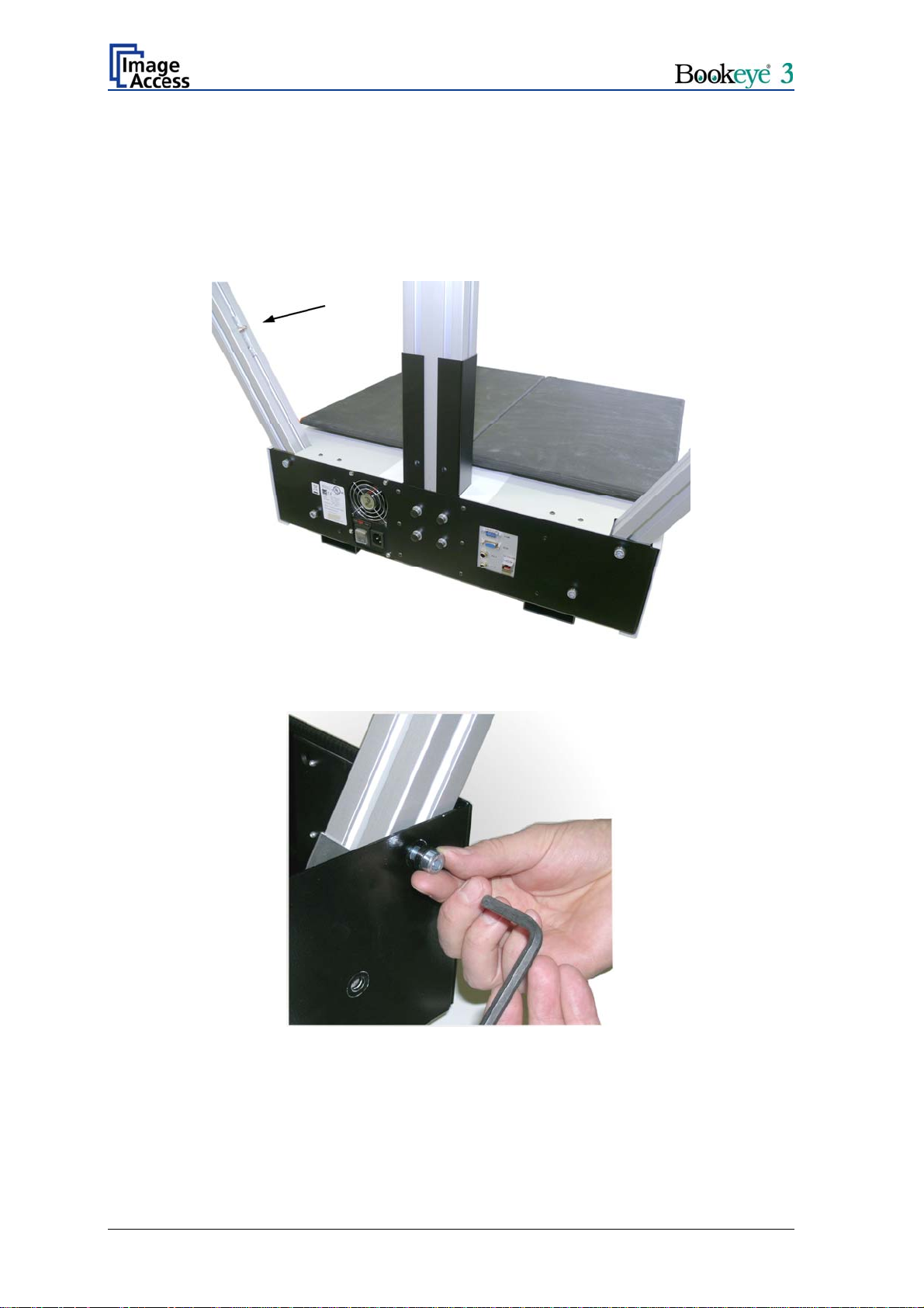
The glass plate is fixed to the scanner with two Allen screws M8x12 for transporting.
Remove the Allen screws and keep them for later use.
Picture 16: Removing the transport screws
Lift the glass plate off and store it temporarily in a place where it cannot be broken.
Storing it in the transport box is recommended.
Insert eight Allen set screws M8x8 into the fastening elements where the transport Allen
screws were removed.
Pull the book cradle plates out of the body element.
Remove the countersunk socket screws between the book cradle drives. Use the 4 mm
Allen wrench.
Picture 17: Removing the countersunk socket screw
Page 22 Setup and Assembly Manual
Page 23
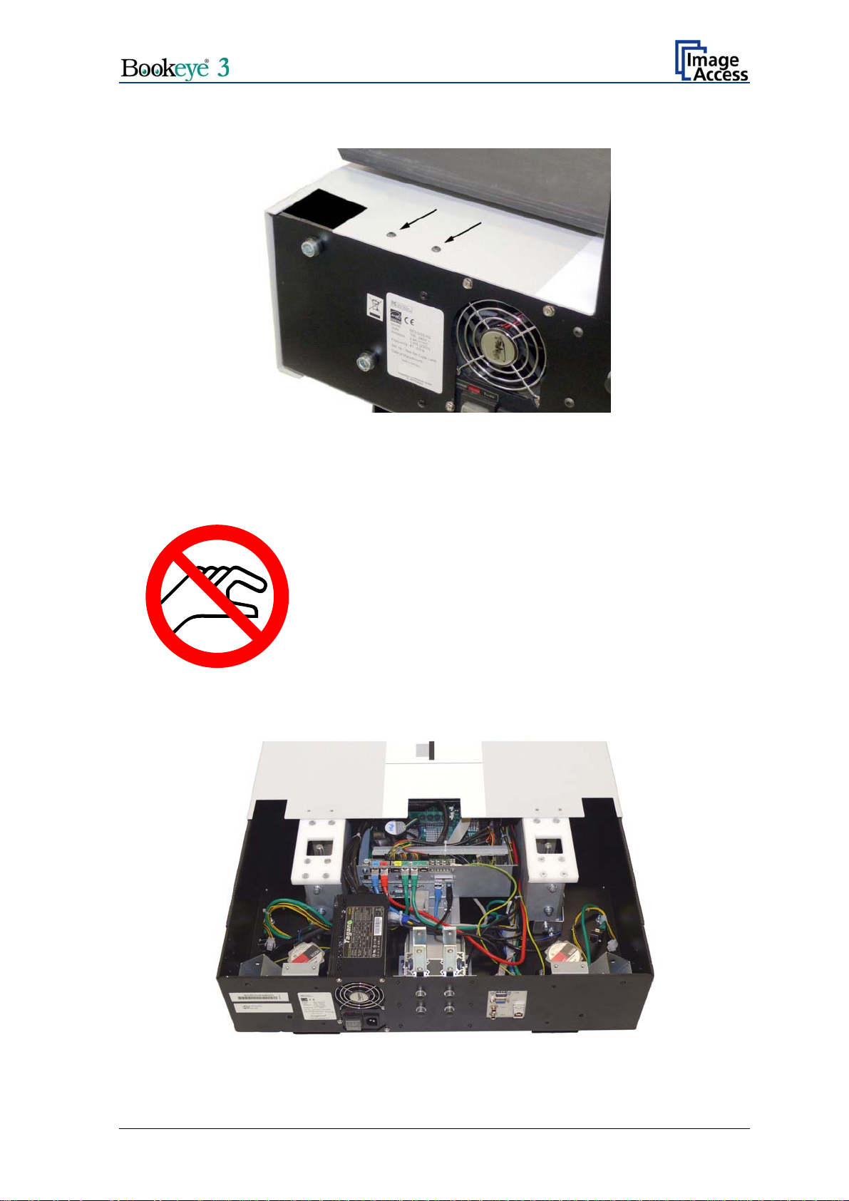
Picture 18: Remove marked screws
Remove the four screws at the back of the housing between the openings for the lamps
and the neck opening.
CAUTION!
Danger of injury!
Never put your fingers in the driving element openings.
Slide the body element cover approximately 300 mm (≈ 12 inch) to the front side. This will
make the lamp holder brackets and the mounting brackets for the camera neck
accessible.
Picture 19: Body element cover opened
Setup and Assembly Manual Page 23
Page 24
Insert the lamps into the lamp holder brackets in the body element. The lamps have preinstalled fixtures for the gas spring. The fixtures must be positioned at the inside near to
the camera neck. Picture 20 shows the position of the fixture in the right lamp.
Note: The definition of “right side” and “left side” always refers to the normal operating
position, i.e. from the front side of the scanner.
Picture 20: Position of gas spring fixture at right lamp
Fix each lamp with two Allen screws M8x12. Use a plastic washer with each screw.
Picture 21: Fixing the lamp
Connect the two lamp cables to the corresponding connector in the body element.
Page 24 Setup and Assembly Manual
Page 25

Before inserting the camera neck into the body element, slide the black cover over the
neck. The open side of the cover must be placed to the back of the camera neck. Picture
20 shows the correct position of the cover on the camera neck.
The position of the T-slot nuts in the camera neck front side should match with the
boreholes in the front of the black cover. They will be used later to hold the glass plate
bearing.
Picture 22: Camera neck assembly
Note: It is recommended to perform the next steps with two persons. One person holds
and positions the camera neck while the second person handles the cables.
Slide the complete camera neck over the mounting brackets in the body element. Press
the flexible tube a little at the outside. Picture 22 shows how to place the flexible tube with
the cables between the mounting brackets.
Fasten the camera neck at the front and back with the Allen set screw M8x8.
Picture 23: Front side Picture 24: Back side
Setup and Assembly Manual Page 25
Page 26

Connect the camera neck cables to the sockets at the connector board which is found
directly in opposite to the fastening elements of the camera neck. The connectors are
marked with colored labels. Always connect cables with matching colors.
Picture 25: Connector board with camera neck cables
The connector for the flat ribbon cable has no colored label, but is easily identified by its
characteristic form.
Picture 26: Connector of flat ribbon cable
Check all connectors and cables for secure
connection. It is recommended to position the cables
in a loop as shown in the picture on the left.
Picture 27: Cable loop
Page 26 Setup and Assembly Manual
Page 27

Slide the body element cover slowly back on the body element.
Important: While moving the body cover back on the body element, watch the
keyboard cable (item (1) in the picture below). Picture 28 shows how to
hold the keyboard cable.
Picture 28: Keyboard cable while moving the body cover
Pull the keyboard cable carefully in arrow direction until the edge of the body cover
reaches the edge of the power supply. Then release the cable and slide the body cover in
its final position.
Picture 29: Body cover at edge of power supply
Insert the screws in the following order:
1. The two countersunk socket screws between the driving elements of the book cradles.
2. The four lens head screws at the back of the housing, between the lamps and the
camera neck.
3. The six Allen screws at the bottom.
First, fasten the screws loosely. Check the position of the body element cover again and
tighten all screws securely.
Setup and Assembly Manual Page 27
Page 28

A.2.3 Assembling the Glass Plate
Insert the book cradle plates into the driving elements and place the foam rubber mats on
the plates.
Connect the scanner to the mains power and switch it on with the main power switch. The
main power switch is found on the rear side of the scanner, next to the power connector.
The green START LED on the keyboard lights up. This signalizes that the scanner is in
stand-by mode.
Press the green START button to start the scanner. When the start sequence is finished
after approximately 30 seconds, the display shows: READY TO SCAN
The book cradle plates are controlled by the eight buttons in the middle of the keyboard
field.
Picture 30: Book cradle controller
Press and hold the upper button with the double arrow to move both book cradle plates
upwards simultaneously. At the upper end position, the book cradle motors stop
automatically.
Place the glass plate on the book cradle plates. The position of the bearing in the middle
of the glass plate must match with the boreholes in the black cover. Insert two Allen
screws, M8x12, into the bearing and fix it to the camera neck.
Picture 31: Bearing in the center of the glass plate
Page 28 Setup and Assembly Manual
Page 29

Place the T-slot nuts in each lamp at a position corresponding to the position of the axes
at the right and left side of the glass plate.
Picture 32: T-slot nut in corresponding position
Slide a hinge on each axis.
Fix each hinge to the lamp with an Allen screw M8x12.
Picture 33: Hinge mounted at right lamp
Setup and Assembly Manual Page 29
Page 30

Each gas spring has on its ends special locking springs inserted.
Important: The locking springs always must be removed before placing or removing
the gas springs at the glass plate or on the pin at the lamps.
Picture 34: Position of locking springs
Picture 34 shows the position of the locking springs at the lamp and at the glass plate.
When the scanner is delivered, the gas springs are already mounted to the lamps. They
only must be mounted to the glass plate.
To mount the gas springs to the glass plate, remove only the locking spring at the glass
plate side of the gas spring.
At first turn the locking spring (1.) over the ball head of the gas spring. It needs a little
force to move the spring over the ball head.
Then pull it out of the boreholes (2.).
Picture 35: Removing the locking spring
Page 30 Setup and Assembly Manual
Page 31

Open the glass plate completely, hold it in this position and click the gas spring onto the
pin of the glass plate.
Picture 36: Gas spring mounted to glass plate
Repeat the procedure with the second gas spring.
Finally insert the locking springs at both gas springs.
Picture 37: Locking spring inserted
Picture 38: Locking spring locked
Setup and Assembly Manual Page 31
Page 32

Picture 39: Gas spring completely mounted
The opening angle of the glass plate can be modified by moving the fixtures in the lamps.
Note: Modifying the opening angle of the glass plate should only be done with the help of
a second person!
Open the glass plate completely. One person must hold the glass plate in this position
while the second person opens the Allen set screw in the fixture slightly.
The opening angle can now be modified. When the glass plate opening angle is set to the
desired position, the Allen set screws must be fastened securely.
Page 32 Setup and Assembly Manual
Page 33

A.2.4 Setting the Initial Lamp Position
The lamp position must be initialized after assembling the Bookeye® 3 scanner. The
reason for this procedure is as follows:
The scanners lamps turn under software control and project a vertical beam of light onto
the scanning surface. Both lamps and the CCD have to move perfectly synchronized to
achieve the highest brightness level during the whole sweep.
The scanner’s CCD motor and the lamp motors form an electronic gear that performs very
complex movements under software control while scanning books and other objects that
are not completely flat. This only works if the initial position after a power up cycle is in a
known state.
Each lamp has a home position switch that acts as a reference. When a lamp is
assembled into the scanner, the light beam position relative to the home position switch is
unknown. To make known all positions of the above described electronic gear, the
following initialization has to be executed.
All positions in the electronic gear are adjusted via software later but the initial adjustment
must be made manually.
The initialization of the lamps is done in two steps.
• The first steps is the mechanical adjustment. For the mechanical adjustment the
keys for book cradle control will be used.
• The second step is the electronic adjustment. The electronic adjustment will be
controlled by the device firmware and runs fully automatically.
During the mechanical adjustment of the lamps the keyboard display shows some
information.
Start the Bookeye® 3 scanner. After some internal tests have been performed, the display
will show the message READY TO SCAN.
Setup and Assembly Manual Page 33
Page 34

A.2.4.1 Performing the mechanical adjustment of the lamps
The keys for the book cradle control are located in the center of the keyboard, see figure
below.
Figure 1: Book cradle control keys
To initialize the lamps, the scanner must be switched to the lamp initializing mode.
Press and hold the two keys in the middle of the book cradle control field and
simultaneously press the green START button (Picture 40).
Picture 40: Press the keys simultaneously
The lamps light up and move to their start positions.
The display shows
Adjust the light beams
Read spec for more info!
The scanner plays the sound “Attention please!” to indicate that it is in the initialization
mode.
Note: If no key is pressed for approx. 20 seconds the scanner ends the initialization
mode automatically. The sound “OK” will be played and the display shows
Saving new positions
Page 34 Setup and Assembly Manual
Page 35

If the lamps are in their start positions, the maximum light level must be present at the left
edge and the right edge of the book cradle respectively.
Picture 41: Lamps in start position
The position of the left lamp is changed by pressing the left up/down key of the keyboard.
The position of the right lamp is adjusted accordingly with the right up/down key of the
keyboard.
Picture 42: Up/down key on right side of keyboard
Press the keys to move the light beam on the book cradle. The upper key moves the light
beam to inside of the book cradle, the lower key moves the light beam to the outside.
Setup and Assembly Manual Page 35
Page 36

At the top of the lamp arm, the light beam is also visible. It is helpful to check the light
beam at both positions to finally leave it in the correct position.
Picture 43: Light beam on right side of the book cradle
Press the down key to move the light beam to the
outside.
Press the up key to move the light beam to the inside.
The above pictures show the right lamp. Corresponding steps must be performed for the
left lamp.
Page 36 Setup and Assembly Manual
Page 37

The two screw head caps at the upper end of the lamp arm help to set the light beam to
the best position.
Picture 44: Light beam adjusted
A.2.4.2 Saving the lamp positions
Press the green START button to save both lamp positions.
The sound “OK” will be played and the display shows
Saving new positions
The lamp positions will also be saved automatically when the time out period has passed
without any activity.
A.2.4.3 Leaving the initialization mode without saving
Press the red STOP button to leave the initialization mode. The lamp positions will not be
saved.
Setup and Assembly Manual Page 37
Page 38

A.2.4.4 Lamp position control mode
The position of the lamps and their maximum travel distance can easily be checked
through the values shown in the keyboard display in this control mode.
The scanner must be in the “lamp initialization mode”. To switch the scanner to the “lamp
initialization mode”, use the key combination as described in chapter A.2.4.1.
+
+
Press the left or right up key together with the cradles up key
or
press the left or right down key together with the cradles down key
The display will change to the “lamp position control mode”.
The display shows two values for each lamp:
SW: <value>
Shows the current rotation angle of the lamp, measured from the position of the reference
switch. The position that activated the reference switch is defined as the zero point for the
lamp movements.
ABS: <value>
Shows the angle the lamp has moved after pressing the button combination. It is assumed
that the lamps have been manually adjusted to be optically straight as described in
chapter A.2.4.1
With the key combination described above, the lamps will move at a higher speed than
with the up key or down key only.
In this mode, the lamps can be moved to their maximum positions for testing purposes.
The function of the home position switch and its position can also be tested in this mode.
NOTE: If the lamp is moved beyond its normal maximum position, the scanner plays the
warning sound: “Attention”
This lamp position can not be saved for safety reasons.
This mode ends automatically after a short time-out period or directly after pressing the
STOP button on the scanner keyboard.
The lamps must be able to freely move within an angle of +/- 45° before they touch their
corresponding mechanical end position. The minimum requirement is that they move 45°
in the direction of the scanning bed; a limitation in the other direction can be tolerated. If
that limitation exists on one lamp, they can also be swapped to continue working with the
scanner.
The reference switch position is also of importance. The switch should be activated shortly
before the lamp is blocked. A distance of an angle of 2 – 4° is ideal, higher values are no
concern, lower values must be corrected. The correction is done by bending the sheet
metal piece that activates the switch.
Page 38 Setup and Assembly Manual
Page 39

B Software Setup
B.1 Setup Network IP Address
After shipment or after a reset to factory defaults, the scanner will have the
default IP address 192.168.1.50.
This IP address is most likely not a valid address in your local network, therefore the
address has to be changed.
To perform this, a connection to the scanner must be established. First, note all network
settings in your local PC. Then change the settings in your local PC to IP address
192.168.1.1 and subnet mask to 255.255.255.0.
Enter the IP of the scanner into your browser. The start screen of the scanner opens.
Picture 45: Start screen
In the start screen go to Setup Device .
Setup and Assembly Manual Page 39
Page 40

Choose the login level Poweruser using the default password "Poweruser".
Picture 46: Login level screen
In the Base Settings section click at Network Configuration .
Picture 47: Poweruser Main Menu screen
Page 40 Setup and Assembly Manual
Page 41

Now change the IP address, subnet mask and gateway to a valid address or select DHCP
to obtain an IP address automatically.
Picture 48: Network configuration screen
If the IP address has been changed, the device has to be powered down and up again.
Change the settings of your local PC back to the previous network settings. Enter the new
IP address of the scanner and go to the “Poweruser” main menu again.
Setup and Assembly Manual Page 41
Page 42

B.2 Mandatory Optical Adjustments
Whenever the device is setup for the first time, moved to a different location, cleaned or
serviced and after a software update; some adjustments have to be performed to
guarantee maximum quality and accuracy.
Access to these functions is only possible through the login level “Poweruser”, default
password “Poweruser”. The person having access to this level can change the password
and thereby limit access to normal operators.
The following functions use special test targets that were supplied with the scanner. Do
not try to perform any of these adjustments without the proper test targets.
The Bookeye
— White Reference Target 110x670
— Line Reference Sheet LRS-200
Please ensure that adjustments are made following the sequence below.
1. Perform the Scan Start function. This will synchronize the CCD main drive motor
®
3 scanner is delivered with the following test targets:
with the lamp motors so that the CCD is centered along the horizontal axis and the
lamp beams follow as precisely as possible.
2. Execute the Auto Focus function to establish a basic reference for the focus
motor. This function should also be invoked any time the scanner seems to be out
of focus.
3. The next step is the White Balance function. This calibrates the scanner’s CCD
and optics relative to the lamp light and the remaining ambient light. This function
should be invoked if the brightness seems to have shifted, the ambient light
situation has changed significantly or the images have horizontal stripes on them.
4. The next step is the Laser Check function. This function checks all properties of
the laser line and will return overall skew and position of the laser line.
Page 42 Setup and Assembly Manual
Page 43

All adjustments described in chapter B.2 and its subchapters start from the main screen of
the login level ”Poweruser”.
Start your browser software. Enter the IP address of the scanner in your browser to open
the start menu.
Picture 49: Scan2Net Start screen
In the start screen go to Setup Device .
Choose the login level Poweruser using the default password "Poweruser".
Picture 50: Buttons for login levels
The next screen shows the main menu screen.
Setup and Assembly Manual Page 43
Page 44

Locate the section Adjustments & Support and go to Adjustments .
Picture 51: Poweruser Main Menu screen
Start in section Focus & Scan Area Adjustments. Select the appropriate menu items as
described in the following paragraphs.
Picture 52: Adjustment & Support screen
Page 44 Setup and Assembly Manual
Page 45

B.2.1 Scan Start
This function adjusts the position of the CCD camera and the lamps relative to each other.
The electronic gear mentioned previously is fine-tuned with this routine. The first test
performed is the maximum turn of the lamps. The lamps will hit against their mechanical
end position, which will produce an audible sound. This is necessary to check whether the
lamps can be turned in and out far enough.
Then the scanner scans the test target, finds the white to black change in the middle of
the test target and takes this position as the optical middle. It is very important to move the
test target against the neck and center it as precisely as possible. Any deviation of the test
target in the horizontal direction from the ideal position will be present in all scans
afterwards.
After the optical middle is established, the scanner moves its CCD camera to the newly
found middle position. Both lamps are moved backward and forward to find the maximum
brightness of the beam. When the position is found it is stored. This will override the
previous manual setting. The manual setting was necessary to have at least some
synchronized lights during the first step when the scanner tries to locate the optical
middle.
To perform the function follow the steps 1) and 2) as described on the screen.
Picture 53: Scan Start adjust screen
Press the Next Step button.
Setup and Assembly Manual Page 45
Page 46

After a short time, the scanner will return some measured values. The detailed values are
only of interest for trained service technicians. As long as the results are all shown in
green text, the device is properly calibrated.
An error is always shown in red text and usually comes with an explanatory remark.
Picture 54: Scan Start results
1. Click the button New Values in the section Controls to repeat the measurement.
Or
2. Click the button Back to Adj. Menu in the section Menu controls to return to the
adjustments menu (see Picture 52).
Page 46 Setup and Assembly Manual
Page 47

B.2.2 Auto Focus
This function automatically locates the lens position for the highest level of sharpness and
best image quality.
First, select the current glass plate position.
This value measured with the selected glass plate position is the reference for all focus
adjustments used later during e.g. book fold correction, folder mode scanning or fixed
focus scanning.
Picture 55: Available glass plate positions
Press the Next Step button below the picture corresponding to the selected glass plate
position.
Setup and Assembly Manual Page 47
Page 48

B.2.2.1 Auto Focus Measurement with Glass Plate Opened
Perform the measurement as follows:
3. Open the scanner’s book cradle completely, as shown on the screen.
Note: The position of the book cradles is verified. If the book cradles are not in the
lowest (home) position, a Retry button and a message are displayed on the
screen instead of the Next Step button .
4. Press the Next Step button. The measurement starts.
Picture 56: Auto Focus measurement with open glass plate
After the Autofocus function has completed, the results will be displayed. Values displayed
in green indicate valid results. Any error will be shown in red text, followed by some
explanatory remarks.
Note: It is normal that the measurement will return different values each time the
measurement is repeated. The lens motor has a very high resolution and the
best focal point has to be found in the already large focal range, therefore a
variation of 50 – 100 in values is normal.
Page 48 Setup and Assembly Manual
Page 49

Picture 57: Auto Focus results
5. Click the button New Values in the section Controls to repeat the measurement.
Or
6. Click the button Back to Adj. Menu in the section Menu controls to return to the
adjustments menu (see Picture 52).
Setup and Assembly Manual Page 49
Page 50

B.2.2.2 Auto Focus Measurement with Glass Plate Closed
Perform the measurement as follows:
7. Close the book cradles.
8. Place the Line Reference Sheet S2N LRS-200 on the scanner’s book cradle as
shown on the screen and align it as described.
9. Move the book cradles to the upper position. Close the glass plate.
Note: The position of the book cradles is verified. If the book cradles are not in the
upper position a Retry button instead of the Next Step button and a
message is displayed on the screen.
Picture 58: Information about book cradles position
After moving the book cradles to the upper position press the Retry button.
Page 50 Setup and Assembly Manual
Page 51

When the book cradles are in the upper position the screen shows the following:
Picture 59: Auto focus measurement screen
10. Press the Next Step button The measurement starts.
After the Autofocus function has completed, the results will be displayed. Values displayed
in green indicate valid results. Any error will be shown in red text, followed by some
explanatory remarks.
Note: It is normal that the measurement will return different values each time the
measurement is repeated. The lens motor has a very high resolution and the
best focal point has to be found in the already large focal range, therefore a
variation of 50 – 100 in values is normal.
11. Click the button New Values in the section Controls to repeat the measurement.
Or
12. Click the button Back to Adj. Menu in the section Menu controls to return to the
adjustments menu (see Picture 52).
Setup and Assembly Manual Page 51
Page 52

B.2.3 Scan Center
This function is fully manual.
The optical middle in the driving (horizontal) direction has already been corrected by
adjusting the distance between the home position of the camera and the optical middle
position.
In contrast, the vertical middle cannot be adjusted but is found at a certain pixel position
on the CCD. If an individual scanner head is slightly tilted towards the front of the scanner,
the camera’s middle position also moves in the same direction and the scanner “sees”
more area at the keyboard side of the scanning bed.
Since all scanners have some spare pixels that are not used, the middle can be adjusted
by defining a certain number of pixels at the lower edge of the scanning bed which the
scanner should ignore.
The input field only takes positive values, the unit is pixels.
Perform the function as follows:
13. Press the Scan Center button in the Adjustments & Support screen (Picture 52).
Type in the offset value in pixels.
Picture 60: Scan Center screen
14. Press the Adjust value button to permanently store the value.
15. Click the button Back to Adjustment Menu to return to the adjustments menu.
Page 52 Setup and Assembly Manual
Page 53

B.2.4 White Balance
B.2.4.1 Some Basic Information
The white balance function is the most important function for consistent image quality.
This is especially important in the type of open scanning environment present in planetary
scanners.
Although all scanners have a function similar to the white balance, the light situation inside
a flatbed scanner is much more controlled than with the Bookeye® family of scanners. A
normal flatbed scanner has to be calibrated once in a while, maybe every couple of
weeks. This is necessary to compensate for light degradation, accumulation of dust, loss
of sensitivity of the CCD and other long term effects.
By contrast Bookeye® scanners have to be calibrated more than once a day if the
ambient light situation changes significantly.
To be able to fully understand the results of a white balance, the following
information is helpful:
The scanner has built in light sources of known and stable quality consisting of the most
state-of-the-art white LEDs but generally receives some significant ambient light from the
ceilings or windows of unknown intensity, color temperature and usually with some
amount of flicker.
During the white balance measurement, all internal and external light sources are
combined and illuminate the target. The intended target for this function is the
White Reference Target 225x670, which has a very even, non-glossy and extremely
white surface.
In the first step, the overall sensitivity of the scanner is adjusted in such a way that the
brightest area results in an almost saturated output signal. This assures that the largest
density range possible is used. After this adjustment is done, the uneven light distribution
on the CCD caused by the imbalance of the lamps, the ambient light introduced, the
imperfections of the lens and other factors; has to be compensated for. This measurement
results in a correction function that has higher correction factors at the upper and lower
edges of the scan bed and almost no correction in the vicinity of the brightest area.
If the above is understood, it is understandable that the quality of the test target is of
utmost importance to the result of the white balance. The test target is a reflective one and
reflects the light in a diffuse way. If the test target has dirt, wrinkles or anything on it visible
to the human eye, the CCD will also see this and will overcompensate in these areas.
Although the internal software has been programmed to eliminate these imperfections to a
certain degree, it still leads to unreliable results if the target is not good enough.
If the target is good enough and ambient light level is not too high, the scanner will
calibrate successfully. Calibration means that the “white” of the test target in the given
illumination situation produces a “white” output in the digital domain. Consequently, all
scans of white paper that has different properties than the test target results in brightness
and possibly color shifts. Because the inexperienced user may become irritated if the
“white” paper turns out to be lightly grayish and somewhat uneven; many competitors
clamp the brighter pixels to fully white. This looks better but introduces artifacts, therefore
this is only optional with a Bookeye®.
Setup and Assembly Manual Page 53
Page 54

There are three ways to change the result of the white balance.
The first way is to use the Brightness Correction button in the white balance menu. This
button changes the gains settings up to ± 2dB, while positive values make the scans look
brighter.
Picture 61: Brightness Correction Factor screen
The second way of changing the results is invoked if the individual R G B controls in the
scanner application are used. They allow changing the color temperature of the original
reference scan.
Picture 62: R G B controls
The third way is the easiest and most straightforward method. Change the target. If
scanning newspaper is the goal, the white balance could be performed on a blank section
of a newspaper page. This will turn all other scanned pages to white in the digital domain.
Page 54 Setup and Assembly Manual
Page 55

B.2.4.2 White Balance with Glass Plate opened
Start in the Adjustments & Support screen (Picture 52).
Perform the measurement as follows:
1. Find the section White Balance Adjustments and click the button White Balance .
Picture 63: Glass plate positions for white balance
Press the Next Step button below the picture corresponding to the selected glass plate
position.
2. Close the book cradles completely and move them to the lowest position.
Note: The position of the book cradles is verified. If the book cradles are not in the
lowest (home) position, a Retry button and a message are displayed on the
screen instead of the Next Step button.
After moving the book cradles to the lowest position press the Retry button.
Setup and Assembly Manual Page 55
Page 56

3. Place the White Reference Target 225x670 at the marked position.
Picture 64: White Balance screen, glass plate opened
4. Press the Next Step button. The measurement starts.
After the Autofocus function has completed, the results will be displayed. Values displayed
in green indicate valid results. Any error will be shown in red text, followed by some
explanatory remarks.
5. Click the button Back to Adjustment Menu to return to the adjustments menu.
Page 56 Setup and Assembly Manual
Page 57

B.2.4.3 White Balance with Glass Plate closed
Start in the Adjustments & Support screen (Picture 52).
Perform the measurement as follows:
1. Find the section White Balance Adjustments and click the button White Balance .
Press the Next Step button below the picture corresponding to the selected glass plate
position. Picture 63 shows the available positions of the glass plate.
2. Close the book cradles completely and move them to the upper position.
Note: The position of the book cradles is verified. If the book cradles are not in the
upper position a Retry button and a message are displayed on the screen
instead of the Next Step button.
After moving the book cradles to the upper position, press the Retry button.
3. Place the White Reference Target 225x670 at the marked position.
Picture 65: White Balance screen, glass plate closed
4. Press the Next Step button.
After the Autofocus function has completed, the results will be displayed. Values displayed
in green indicate valid results. Any error will be shown in red text, followed by some
explanatory remarks.
5. Click the button Back to Adjustment Menu to return to the adjustments menu.
Setup and Assembly Manual Page 57
Page 58

B.2.5 Laser Check
This function checks the integrity and position of the laser line. The function will return
skew and relative position to its ideal values and is used to track potential misalignment.
Start in the Adjustments & Support screen (Picture 52).
Perform the measurement as follows:
1. Find the section Focus & Scan Area Adjustments. Press the Laser Check button.
Note: The position of the book cradles is verified. If the book cradles are not in the
lowest (home) position a Retry button instead of the Next Step button and
a message is displayed on the screen.
After moving the book cradles to the lower position press the Retry button.
2. Place the White Reference Target 225x670 at the marked position.
Picture 66: Laser Check screen
3. Press the Next Step button. The measurement starts.
Page 58 Setup and Assembly Manual
Page 59

4. After the function has finished, the results will be displayed. As long as the displayed
text is green, the result is ok. Any error will be shown in red followed by some
explanatory remarks.
Picture 67: Laser check result
5. Click the button New Values in the section Controls to repeat the measurement.
Or
6. Click the button Back to Adj. Menu in the section Menu controls to return to the
adjustments menu (see Picture 52).
At this point, all mandatory setup functions have been completed. Click the
Scan2Net logo on top of the screen and go to Launch Scan Application to start
scanning.
Setup and Assembly Manual Page 59
Page 60

B.3 Options and Settings
The following options and software settings are optional and are not necessary for the
basic operation of the device. Some of them provide more convenience for the operator
while others are software options that can enhance image quality or perform other
optional functions.
B.3.1 Time Server
Locate the section Base Settings in the Poweruser screen.
Click the button Adjust Time & Date to set various parameters.
Picture 68: Adjust Time & Date screen
Select time format, time zone, daylight saving and time server IP address. Manually set
time or let the system set it at every power up.
Note: The default image name contains current time and date, therefore
synchronizing the internal clock is recommended
Page 60 Setup and Assembly Manual
Page 61

B.3.2 Sound Control
Locate the section Base Settings in the Poweruser screen and go to Sound System .
The volume can be adjusted and other sound files can be uploaded.
Picture 69: S2N Sound System screen
A sound file can be assigned to various action items. The assigned sound will be played
every time the condition occurs. The default setting can be overwritten by selecting the
appropriate WAV file and then moving it over by pressing the Å button.
Picture 70: Link Sounds to Events screen
Setup and Assembly Manual Page 61
Page 62

B.3.3 Firmware Update
Locate the section Updates & Uploads and go to Update Scanner Firmware .
Select the “Post update behavior” of the scanner from the list.
Picture 71: Update Scanner firmware screen
Browse and select the previously downloaded firmware update file.
The appropriate firmware can be downloaded from the Image Access Customer Service
Portal at http://service.imageaccess.de
.
Page 62 Setup and Assembly Manual
Page 63

B.3.4 Install Options
Locate the section Updates & Uploads and go to Install Options .
All option keys displayed in green are valid and installed. A new key must be entered
completely without blanks or spaces followed by the Apply button. If the key text does
not turn green, the key is invalid or does not belong to this specific scanner or option.
Note: Option keys are valid only for one option on a specific scanner denoted by its
serial number.
If a key is accidentally deleted it can always be obtained again at the Image
Access Customer Service Portal http://service.imageaccess.de
cost.
without extra
Picture 72: Install Option screen
Setup and Assembly Manual Page 63
Page 64

B.3.5 Install ICC Profiles
Locate the section Updates & Uploads and go to ICC Profiles .
Picture 73: ICC Profile screen
Select either Printer Profiles or Scanner Profile .
In the next screen, browse for a new ICC profile and select it. It will replace the previous
file.
Page 64 Setup and Assembly Manual
Page 65

C Tests and Troubleshooting
C.1 Network Performance Test
It is sometimes desirable to check network performance if the scanner seems to be
operating slowly. The scanner itself has a gigabit network interface and can transfer data
at a sustained rate of almost 100Mbytes per second. This is far more than most standard
PCs can handle and comes very close to the maximum bandwidth of the gigabit network.
If the scanner runs in a 100Mbit networks it is already slowed down significantly,
particularly if the file sizes are large. Sometimes the network’s response times are poor
because routers and/or switches with slow performance are used, or the topology of the
network is not optimal.
This analyzer checks the response time between the scanner and any arbitrary IP
address in the network. In most cases, the IP address would be the one from the PC
operating the scanner, but FTP links can also be checked via this function.
Perform the test as follows:
Locate the section Adjustments & Support and go to Network Analyzer .
Go to Perform Speed Test .
Picture 74: Perform Speed Test screen
Setup and Assembly Manual Page 65
Page 66

Type in a valid IP address in the same network and subnet.
Picture 75: Network Analyzer Parameters screen
Check the results in the following screen. Single digit millisecond response times are
good, the example shown is from a well structured gigabit network.
Picture 76: Network Analyzer Result screen
Page 66 Setup and Assembly Manual
Page 67

C.2 Scan Test Targets
The scanner has a function for scanning specific test targets. If one of the test targets is
scanned, all image parameters are set to a known state to enable a remote system to
analyze the quality of the scanner. One or more CSTT test targets are included in the
initial scanner shipment. They are used to troubleshoot various types of image quality
problems. Any time Image Access support is contacted, you will be asked to provide a
test scan of the CSTT target.
Image Access is the first vendor that has established a portal with an Image Quality
Server online 24 hours at 7 days a week. The Image Quality Server can be reached at
http://service.imageaccess.de
black points, geometric distortions, resolution and many more parameters and displays
them in an easy to understand form. A time stamped certificate can be printed out to
document the scanner’s quality level at any given time.
C.2.1 Scan CSTT Test Target
Locate the section Adjustments & Support, go to Scan Test Targets and click the
button Scan CSTT Test Target .
. The server automatically analyzes color tracking, white and
Picture 77: Scan Test Target screen
Place the CSTT test targets on the scanner as displayed.
Picture 78: CSTT Test Target screen
Press the Next Step button and follow the instructions.
Setup and Assembly Manual Page 67
Page 68

C.2.2 Scan IT8 Test Target
The test scan of a standard IT8 test target is used to generate an ICC profile for the
specific scanner. The scan can be provided to the Image Access Customer Service Portal
at http://service.imageaccess.de
can then be uploaded into the scanner.
Locate the section Adjustments & Support, go to Scan Test Targets and click the
button Scan IT8 Test Target .
and the system will generate an ICC profile. This profile
Picture 79: Scan Test Target screen
Place the IT8 test targets on the scanner as displayed.
Picture 80: IT8 Test Target screen
Press the Next Step button and follow the instructions.
Page 68 Setup and Assembly Manual
Page 69

C.3 Recovery Function
The recovery function resets all parameters of the device to factory defaults after a fatal
system breakdown.
The recovery key is necessary to invoke the recovery procedure. The key is delivered with
every device. It is marked with the label Recovery.
Important: The recovery function resets the IP address to the factory default value of
192.168.1.50. If the scanner had a different IP address, it will be necessary
to use the cross over cable and change the network settings on the local
computer.
C.3.1 Important Notes before recovering to Factory Defaults
Write down the values for IP address, subnet mask and gateway of the device before
starting the recovery sequence.
The recovering to factory defaults described in the following should only be executed after
a fatal system breakdown!
After recovering to factory default, all firmware updates have to be executed! Make sure
an update file is available on the local computer.
After recovering to the factory defaults, all adjustment procedures described in the
previous sections have to be executed again!
C.3.2 How to Recover to Factory Defaults
1. Power down the device.
2. Plug the recovery key into the serial port at the rear panel of the device.
Picture 81: Connectors on rear panel
3. Power the device up via the start button.
Setup and Assembly Manual Page 69
Page 70

4. When the recovery key is found in the serial port, the recovery sequence is
automatically executed. All viable system data will be restored and necessary repair
steps will be taken without the need of any user interaction.
Important: Do not switch off the device at any time during the recovery procedure!
Note: The recovery sequence can last up to four minutes. While the recovery
sequence is running, no message will be displayed.
5. When the recovery sequence has finished the device will power down automatically.
6. Unplug the recovery key after the device has powered down.
7. Power up the device and launch the scan application in your browser.
The IP address of the device will have the factory default value: 192.168.1.50
8. Change the network parameters to the values which were used before running the
recovery sequence.
Select Setup Device Î Poweruser . Locate the section Base Settings and click
the button Network . Enter the values for IP address, subnet mask, and default
gateway.
Click the Apply button. Confirm the following message by clicking the OK button.
In the next screen click the Reboot button.
Reconnect to the device using the new IP address.
9. Select Setup Device Î Poweruser . Locate the section Updates & Uploads and
click the button Update Firmware . Perform a firmware update.
10. After the firmware update all software adjustments for the device must be performed.
Select Setup Device Î Poweruser . Locate the section Adjustments & Support
and click the button Adjustments . Perform the adjustments by clicking the
appropriate buttons.
Page 70 Setup and Assembly Manual
Page 71

C.4 Troubleshooting Matrix
Problem Possible cause Action
Green start button does not
light up.
Start button does not power
up the device.
Stop button does not power
down the device.
Image is darker than
expected.
Image is brighter than
expected.
Image is darker on one side
than on the other side.
No power Check main outlet, power cord, power-
on switch on the back of the device.
Connector failure, software
glitch …
Internal software hangs,
application hangs …
The target used for white
balance is much brighter
than the scanning target.
The target is much brighter
than the target used for
white balance.
The electronics gear is out
of sync.
Switch power off for at least 10
seconds. Retry after green start button
lights up again.
End all applications and retry. If
problem persists, press the start
button for at least 10 seconds. Power
up again.
Go to the White Balance function
and modify the Brightness Correction
setting.
Go to the White Balance function
and modify the Brightness Correction
setting.
Exercise the Scan Start procedure.
Image shows a color shift
towards red (tint)
Image shows a color shift
towards blue (tint)
Image shows a color shift
towards red (tint)
Image shows areas that are
overexposed and too bright.
The target used for white
balance is more blue than
the scanning target.
The target used for white
balance is more red than
the scanning target.
The scanner receives
significant amounts of
infrared light (sun or spot
lights) not visible to the
human eye.
The scanner receives too
much ambient light from a
point source like sunlight,
spotlight etc.
Go to the RGB adjustments and lower
the gain on red.
Go to the RGB adjustments and lower
the gain on blue.
Change position, close blinds, dim
down or shut off any bright spot lights.
Change position, close blinds, dim
down or shut off any bright spot lights.
Setup and Assembly Manual Page 71
Page 72

Problem Possible cause Action
Image has unevenly spaced
vertical stripes or streaks.
Image has evenly spaced
vertical stripes or streaks.
Image has horizontal stripes
or streaks.
Scanning two A4 (letter)
pages perfectly centered in
A3 (double letter) format
cuts of one side of the scan.
A small portion of the lower
side of the target is missing
in the image.
The image shows an extra
small portion on the lower
side of the target
The electronics gear is out
of sync.
50/60Hz interference from
fluorescent ceiling lights.
Improper white balance.
The scanner’s optical
middle (in the horizontal
direction) is lost or
misaligned.
The scanner’s optical
center (in the vertical
direction) is lost or
misaligned.
The scanner’s optical
center (in the vertical
direction) is lost or
misaligned.
Exercise the Scan Start procedure.
Change position, dim down or shut off
some lamps, change ceiling lights to
electronic ballasts.
Exercise the White Balance
procedure.
Exercise the Scan Start procedure.
Go to the Scan Center function and
lower the value.
Go to the Scan Center function and
raise the value.
The image is out of focus on
a flat target with significant
contrast, book cradles in
their lowest position and flat
mode scanning.
The reference focal point
is lost or misaligned.
Exercise the Autofocus procedure.
Page 72 Setup and Assembly Manual
Page 73

C.5 Error Codes
The scanner does report error conditions on the built in display and through the API.
Some errors are only sent to the API. A green problem description signals that operation
of the scanner is still possible although the error will have an influence on the behavior or
quality of the scanner. If a problem description occurred the device will be stopped and
further scanning is inhibited.
Error # Error message shown in
the display
1 Scanner in use. An attempt to access the scanner was
2 Invalid session ID. An attempt to access the scanner with
4 USER BREAK Stop button pressed. The stop button was pressed during
5 E05 S2N BOARD S2N board failure The S2N board is either not found or
8 User timeout The function ended because of a time
9 Warming up The device is still warming up and
10 Invalid setting value. The value sent to the device is invalid.
11 Setting does not exist. The settings does not exist.
12 Invalid user docsize. The size of the user format is invalid.
14 Invalid resolution or color
15 E15 DOCUMENT
PICKING
20 E20 MOTOR 1/1 (CCD DRV)
SWITCH PERM. OPEN
21 E21 MOTOR 1/1 (CCD DRV)
SWITCH PERM. CLOSED
22 E22 MOTOR 2/1 (L. LAMP)
SWITCH PERM. OPEN
23 E22 MOTOR 2/1 (L. LAMP)
SWITCH PERM. CLOSED
Error message sent to
application
mode.
Document picking error.
Motor 1 / PCI 1 (CCD drive):
End switch permanently
open.
Motor 1 / PCI 1 (CCD drive):
End switch permanently
closed.
Motor 2 / PCI 1 (Left lamp):
End switch permanently
open.
Motor 2 / PCI 1 (Left lamp):
End switch permanently
closed.
Problem description
made from a different application.
an invalid session ID was made.
the operation.
found defective. Make sure board is
sitting correctly on the motherboard.
out
cannot be used.
Either the resolution or the color mode
is invalid.
The parameters that specify the
document picking area are invalid.
The home position switch is
permanently open. The mechanics of
the corresponding motor could be
blocked or disconnected or the
switch/cable is defective.
The home position switch is
permanently closed. The mechanics
of the corresponding motor could be
blocked or the switch/cable is
defective.
The home position switch is
permanently open. The mechanics of
the corresponding motor could be
blocked or the switch/cable is
defective.
The home position switch is
permanently closed. The mechanics
of the corresponding motor could be
blocked or the switch/cable is
defective.
Setup and Assembly Manual Page 73
Page 74

Error # Error message shown in
the display
24 E24 MOTOR 3/1 (R. LAMP)
SWITCH PERM. OPEN
25 E24 MOTOR 3/1 (R. LAMP)
SWITCH PERM. CLOSED
26 E26 MOTOR 4/1 (LENS)
SWITCH PERM. OPEN
27 E27 MOTOR 4/1 (FOCUS)
SWITCH PERM. CLOSED
30 File format not supported. The specified file format is not
55 E55 WRONG S2N HW
CCD PORTS
56 E56 WRONG S2N HW
REVISION NOT OK
60 E60 CAMERA General camera error. General error on the CCD camera
61 E61 CAM N.LOADED
CAMERA 1
62 E62 CAM N.LOADED
CAMERA 2
63 E63 CAM N.LOADED
CAMERA 3
64 E64 CAM DATA BUS
CAMERA 1
Error message sent to
application
Motor 3 / PCI 1 (Right lamp):
End switch permanently
open.
Motor 3 / PCI 1 (Right lamp):
End switch permanently
closed.
Motor 4 / PCI 1 (Lens): End
switch permanently open.
Motor 4 / PCI 1 (Lens): End
switch permanently closed.
Wrong S2N board detected
(not enough CCD ports)
Wrong S2N Board detected
(Revision not OK)
Load camera 1 failed. Initializing of camera 1 failed. Check
Load camera 2 failed. Initializing of camera 2 failed. Check
Load camera 3 failed.
Camera 1 data bus error.
Problem description
The home position switch is
permanently open. The mechanics of
the corresponding motor could be
blocked or the switch/cable is
defective.
The home position switch is
permanently closed. The mechanics
of the corresponding motor could be
blocked or the switch/cable is
defective.
The home position switch is
permanently open. The mechanics of
the corresponding motor could be
blocked or the switch/cable is
defective.
The home position switch is
permanently closed. The mechanics
of the corresponding motor could be
blocked or the switch/cable is
defective.
supported or it is invalid in
combination with the color mode.
The S2N board found is not the right
one for this device. Error can occur
after a repair/exchange. Exchange
with correct board.
The S2N board found is not the right
one for this device. Error can occur
after a repair/exchange. Exchange
with correct board.
board. Check power, cables and S2NPCI board.
power, cables and S2N-PCI board.
power, cables and S2N-PCI board.
Initializing of camera 3 failed. Check
power, cables and S2N-PCI board.
Test data transfer to camera failed.
Check cables / connectors to camera
1 and S2N-PCI board.
Page 74 Setup and Assembly Manual
Page 75

Error # Error message shown in
the display
65 E65 CAM DATA BUS
CAMERA 2
66 E66 CAM DATA BUS
CAMERA 3
67 E67 ADC ERROR
CAMERA 1
68 E68 ADC ERROR
CAMERA 2
69 E69 ADC ERROR
CAMERA 3
75 General keyboard error General keyboard error. Check
99 Internal error. The firmware has detected an internal
Error message sent to
Problem description
application
Camera 2 data bus error.
Camera 3 data bus error. Test data transfer to camera failed.
Camera 1 adc error.
Camera 2 adc error. Test data transfer through analog
Camera 3 adc error.
Test data transfer to camera failed.
Check cables / connectors to camera
2 and S2N-PCI board.
Check cables / connectors to camera
3 and S2N-PCI board.
Test data transfer through analog
digital converter failed. Check cables /
connectors to camera 1.
digital converter failed. Check cables /
connectors to camera 2.
Test data transfer through analog
digital converter failed. Check cables /
connectors to camera 3.
keyboard and cables.
error of unknown cause.
Error # Warning shown in the
display
144 Light level is low
146 W146 LEFT LAMP
BLOCKED
147 W146 RIGHT LAMP
BLOCKED
160 No white balance data No white balance data was found.
180 Deskew failed The deskew function failed.
Warning sent to
Problem description
application
Left lamp blocked. The left lamps travel range is blocked.
Right lamp blocked. The right lamps travel range is
The light level is found to be low
during the white balance function.
blocked.
Perform white balance.
Reposition document.
Setup and Assembly Manual Page 75
Page 76

D Technical Data
D.1 Scanner Specifications
Scan Area
Maximum Scan Area [pixel] 10640 x 7441 Pixel
Maximum Scan Area [mm] 900 x 630 mm
Optical Resolution 300 x 400 dpi
Resolution 75 – 400 dpi
Luminosity
Scanning 4500 LUX
Stand-by (300 sec): 1000 LUX
Stand-by, idle 0 LUX (lamps off)
Lamps:
High Power White LED UV- and IR-radiation free
Lifetime 50.000 hours on-time
Book Cradle:
Maximum load / book cradle plate 15 kg
D.2 Ambient Conditions
Operating Temperature +5 to +40° Celsius
Storage Temperature 0 to +60° Celsius
Relative Humidity 20 to 80% (non condensing)
Noise Level < 50 dB(A) (Operating)
< 30 dB(A) (Stand-by)
Page 76 Setup and Assembly Manual
Page 77

D.3 Electrical Specifications
This device is Energy Star compliant.
Voltage 110–240 VAC
Frequency 50/60 Hz
Power Consumption
Stand-by 6 W
Self-test mode 150 W
Start procedure 260 W
Stand-by, operational, lamps off 105 W
Stand-by, operational, lamps on 140 W
Operating 275 W
Pre-Scan 170 W
Moving the book cradle (lamps on)
Both plates simultaneously 165 W
Single plate 150 W
Moving the book cradle (lamps off)
Both plates simultaneously 130 W
Single plate 115 W
Setup and Assembly Manual Page 77
Page 78

D.4 Dimensions and Weight
Scanner outer dimensions (without lamps) 1250 x 900 x 780 mm (H x W x D)
Scanner outer dimensions (lamps attached) 1250 x 1500 x 780 mm (H x W x D)
Weight of scanner main body 51 kg
Dimensions Transport Box #1
(contains main body, lamps, camera neck, foot
pedal, test targets, assembly material, tools and
cables)
Weight Transport Box #1: 89 kg
Weight of camera head with short neck element: 9 kg
Dimensions Transport Box #2
(contains camera head, manuals and test
targets, optional accessories)
Weight Transport Box #2: 12 kg
490 x 1055 x 945 mm (H x W x D)
540 x 650 x 500 mm (H x W x D)
Total shipping weight 101 kg
Page 78 Setup and Assembly Manual
Page 79

Notes
Setup and Assembly Manual Page 79
 Loading...