

Page 1
O
O
p
p
err
e
attii
a
o
o
n
n
M
M
a
a
n
u
n
all
u
a
This device is compliant.
Page 2

File: BE3-R1-OpMan_Vers-D.doc
Page 3

Introduction
Dear Customer,
We congratulate you on the acquisition of this innovative product from Image Access.
We at Image Access are proud of the work we do; it is the result of our extremely high
standards of production and stringent quality control.
With the Bookeye® 3 scanner, Image Access offers an efficient scanner which covers a
wide scope of applications due to its versatility. Its integrated web based user interface
makes all functions available in structured menus.
This operation manual is designed to lead you through all situations which will arise when
using the Bookeye® 3 scanner.
For this reason, we ask you to read the operation manual attentively before starting to
work with the device. By doing so, you will avoid operation errors and you can control all
functions from the beginning.
In addition please consider the following points:
• Damages to your unit may have occurred during shipping. Please check for
damages immediately after delivery of the unit. Inform your supplier if damage has
occurred.
• Read and ensure that you understand the safety notes. They were developed for
your protection and safety as well as to protect the unit.
• Regular maintenance conserves the high quality and safety of the Bookeye® 3
scanner during the entire service life.
If you have any further questions, please feel free to contact your local dealer or
Image Access directly. Our staff will be happy to help you.
For your daily work with the Bookeye® 3 scanner, we wish you success and complete
satisfaction.
Regards
Your Image Access Team
Operation Manual Page 3
Page 4

About this Manual
Operation Manual
All information about the normal operation and behavior of this device is found in this
Operation Manual. The manual is written for people who only operate the device and do
not perform setup and adjustment procedures. All device elements and software functions
are described in detail, although some of them might never be used. This manual does
not cover any application software like BSW, BSCAN or BCS2. Refer to the appropriate
manual to learn about the application software.
Setup and Assembly Manual
The Setup and Assembly Manual is written for technical staff with some basic
mechanical as well as software skills. Many resellers will offer on-site installation;
therefore, large parts or all of the setup and assembly manual might not be of interest to
the reader. The access level at which these setup and adjustment processes are
performed is called “Power user” and is password protected from access by the normal
operator.
Both manuals can be downloaded from our customer service portal at
http://service.imageaccess.de. Be sure to always check for the latest versions of these
manuals.
The manual is divided into four sections, A to D.
Section A describes the hardware of the device. It shows the connectors as well as all
other elements of the device.
Section B describes the operation software and the keyboard functions.
Section C describes troubleshooting procedures and test scan generation.
Section D shows all technical data and CE, FCC, UL declarations.
© 2005 – 2008 by Image Access GmbH, Germany.
All rights reserved. Reproduction in whole or in part in any form or medium without express written
permission of Image Access is prohibited. Scan2Net™ and other designated brands herein are
trademarks of Image Access.
All other trademarks are the property of their respective owners.
Image Access reserves the right at any time without notice to change said product, product
specification and documentation. For the most recent version, always check our web site
www.imageaccess.de or the customer service portal at http://service.imageaccess.de
Page 4 Operation Manual
Page 5

Version History
Version Published in Content/Changes/Supplements
A April 2006
B August 2006 Second Edition: Chapter A.2.1 added.
C September 2007 Third edition: Some modifications in the integrated S2N user
D August 2008 Fourth edition: New screenshots because of new firmware
First Edition.
interface. Additional parameters in the output options have been
added.
New graphic elements in the S2N user interface.
version 5. A new tab in the S2N user interface enables the user to
define the dimension of user-defined formats more easily.
Operation Manual Page 5
Page 6

Table of Contents
A Hardware Operation -------------------------------------------------------- 11
A.1 Safety Notes ............................................................................................ 11
A.1.1 Marking of Safety Notes 11
A.1.2 Laser Safety Note 11
A.2 Device Overview...................................................................................... 12
A.2.1 Device Location 13
A.2.1.1 Environment 13
A.2.1.2 Ambient Light 13
A.2.1.3 Table 14
A.2.1.4 Power outlet 14
A.2.2 Connecting the Power Source 15
A.2.3 Connecting the Network 15
A.2.4 Connecting a Foot Pedal Switch 15
A.3 Starting the Bookeye® 3 scanner ............................................................ 16
A.3.1 Stopping the Bookeye® 3 scanner 17
A.4 Book Cradle ............................................................................................. 18
A.4.1 Removing the Book Cradle Plates 18
A.4.2 Book Cradle Control Keys 19
A.4.3 Operating the Book Cradle 20
Page 6 Operation Manual
Page 7

Table of Contents, part 2
B Software Operation --------------------------------------------------------- 23
B.1 The Integrated User Interface...................................................................23
B.1.1 The Main Screen 24
B.1.2 The Options Screen 26
B.1.2.1 Book Fold Options 27
B.1.2.2 Fixed Focus Mode 28
B.1.2.3 Embedded Meta Data 29
B.1.3 The Properties Screen 30
B.1.4 The Camera Screen 32
B.1.5 The Settings Screen 37
B.1.6 The Format Screen 39
B.1.7 Output Options 41
B.1.7.1 Output Option Save 42
B.1.7.2 Output Option Print 43
B.1.7.3 Output Option Copy 44
B.1.7.4 Output Option FTP Upload 47
B.1.7.5 Output Option Mail 49
B.1.7.6 Output Option Network 51
B.1.8 The Setup Screen 52
B.2 Laser guided Document Type Detection...................................................60
B.2.1.1 Description of the Laser Purposes 60
B.2.2 Scanning in Fixed Focus Mode 62
B.2.3 Scanning in Flat Mode 62
B.2.4 Scanning in Folder Mode 63
B.2.5 Scanning in Book Mode 64
Operation Manual Page 7
Page 8

Table of Contents, part 3
C Tests and Troubleshooting ---------------------------------------------- 65
C.1 Troubleshooting Matrix ............................................................................ 65
D Technical Data---------------------------------------------------------------- 67
D.1 Scanner Specifications ............................................................................ 67
D.2 Ambient Conditions.................................................................................. 67
D.3 Electrical Specifications ........................................................................... 68
D.4 Dimensions and Weight........................................................................... 69
D.5 CE Declaration of Conformity .................................................................. 70
D.6 FCC Declaration of Conformity................................................................ 71
D.7 Safety Declaration.................................................................................... 71
Page 8 Operation Manual
Page 9

Table of Pictures
Picture 1: Components of Bookeye® 3 scanner................................................................12
Picture 2: Bookeye® 3 scanner back side view.................................................................15
Picture 3: Display before power up....................................................................................16
Picture 4: Book cradle on right side removed....................................................................18
Picture 5: Book cradle Control Keys..................................................................................19
Picture 6: Book cradle at start............................................................................................20
Picture 7: Book cradle at start with glass plate option .......................................................20
Picture 8: Horizontal alignment check ...............................................................................21
Picture 9: Book cradle in the middle of the book ...............................................................22
Picture 10: Start screen .....................................................................................................23
Picture 11: Main screen.....................................................................................................24
Picture 12: Options screen .............................................................................................26
Picture 13: Book Fold Option screen.................................................................................27
Picture 14: Book Fold Option screen.................................................................................28
Picture 15: Metadata screen..............................................................................................29
Picture 16: Properties screen .........................................................................................30
Picture 17: X- and Y Offset definition.................................................................................31
Picture 18: Camera screen.............................................................................................32
Picture 19: DPI mode Fixed...............................................................................................33
Picture 20:DPI mode Flexible ............................................................................................34
Picture 21: Black Threshold slider .....................................................................................35
Picture 22: Gamma slider with preselection buttons..........................................................36
Picture 23: Color Gain screen............................................................................................36
Picture 24: Settings screen ............................................................................................37
Picture 25: List of available languages ..............................................................................37
Picture 26: Skin Selector ...................................................................................................38
Operation Manual Page 9
Page 10

Table of Pictures, part 2
Picture 27: Tool Tips .........................................................................................................38
Picture 28: Status window................................................................................................. 38
Picture 29: Format screen.............................................................................................. 39
Picture 30: Rectangle dragged with mouse....................................................................... 40
Picture 31: "Zoom in" result............................................................................................... 40
Picture 32:Output Option Show......................................................................................... 41
Picture 33: Output Options in Scan Window ..................................................................... 41
Picture 34: Image output option ........................................................................................42
Picture 35: Metadata mask................................................................................................ 42
Picture 36: Output Option Print .........................................................................................43
Picture 37: Available List of Printers for Option Print ........................................................43
Picture 38: Output Option Copy ........................................................................................44
Picture 39: Output Option FTP Upload.............................................................................. 47
Picture 40: Output Option Mail .......................................................................................... 49
Picture 41: Output Option Network.................................................................................... 51
Picture 42: Login screen.................................................................................................... 52
Picture 43: User screen..................................................................................................... 53
Picture 44: Device Info screen ..........................................................................................54
Picture 45: Operation Info screen...................................................................................... 55
Picture 46: User Settings screen....................................................................................... 56
Picture 47: Volume level.................................................................................................... 57
Picture 48: Foot pedal settings.......................................................................................... 58
Picture 49: Splitting Start Page .........................................................................................59
Picture 50: Correct versa incorrect placement .................................................................. 60
Picture 51: Holding down a book....................................................................................... 61
Picture 52: Scanning in folder mode .................................................................................63
Page 10 Operation Manual
Page 11
A Hardware Operation
A.1 Safety Notes
Read and ensure that you understand the safety notes.
The safety notes have been written to ensure your protection and for your safety.
All safety requirements of the following standards
EN 60950
UL 60950
CSA C22.2 No. 60950
are fulfilled by the Bookeye® 3 scanner.
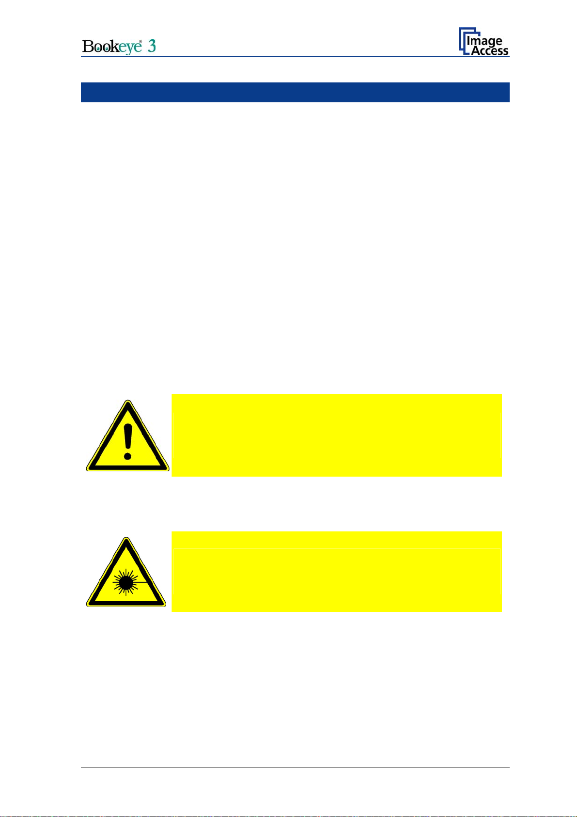
A.1.1 Marking of Safety Notes
All safety notes are marked with a warning sign.
A description of the potential hazard is found at the right side beside the warning sign.
Safety Note!
Text with description of potential hazard.
A.1.2 Laser Safety Note
Safety Note!
Text with description of potential hazard.
Operation Manual Page 11
Page 12
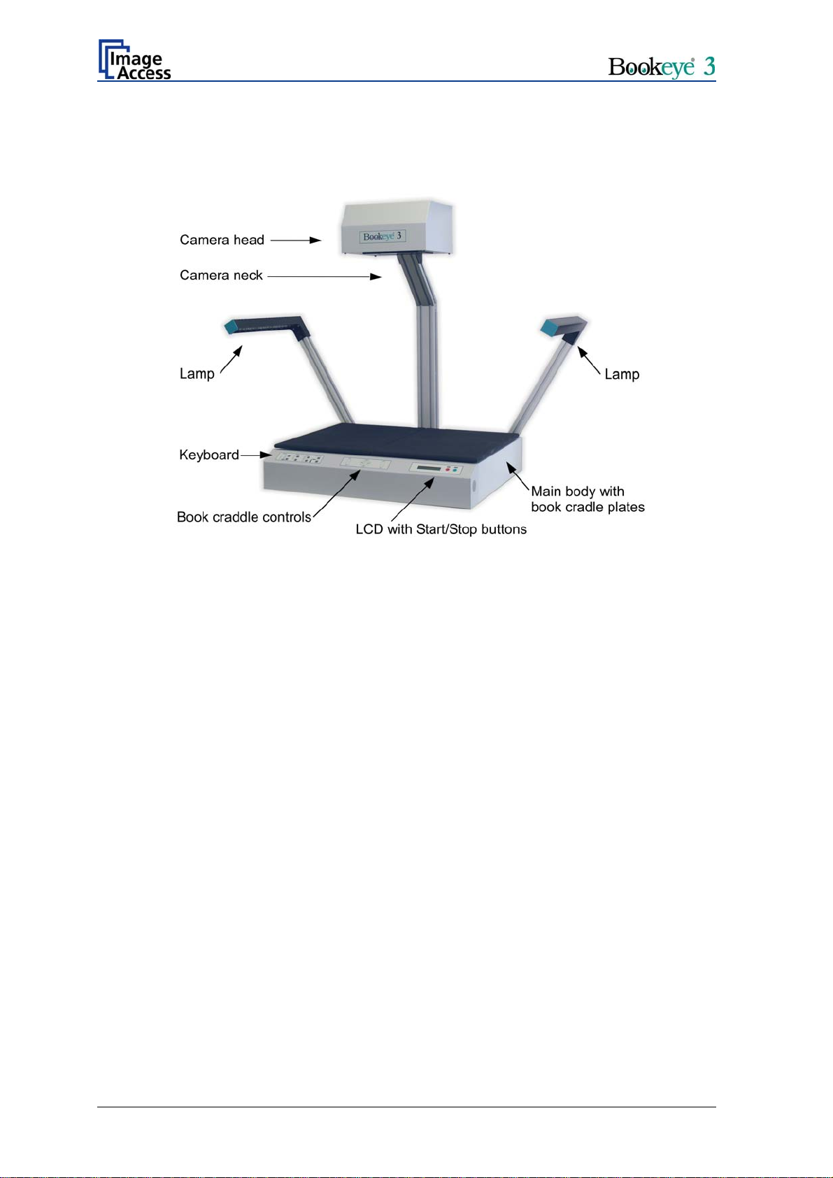
A.2 Device Overview
Picture 1: Components of Bookeye® 3 scanner
For a first look at the Bookeye® 3 scanner, some of the components have been identified
in the above photo. These components are referenced in this operation manual.
The Bookeye® 3 scanner main hardware elements are:
— The main body with two book cradle plates attached.
— Two lamps.
— The camera neck with camera head on top.
— The keyboard with LED display.
Page 12 Operation Manual
Page 13

A.2.1 Device Location
A.2.1.1 Environment
Choose a location that complies with the limits of temperature and humidity. Refer to
chapter 0 for detailed environmental specification.
A.2.1.2 Ambient Light
The location should have a controlled ambient light situation. Light scenarios to avoid are
direct sunlight, spot light from light beams, light sources that cause sharp shadows on the
scanning bed, high levels of ambient light and varying light conditions.
The Bookeye® 3 scanner is an open system with a built-in high quality light source. Open
system means, that the ambient light is added to the light seen by the camera.
The recommended location for the Bookeye® 3 scanner:
• Is not exposed to daylight.
• Is evenly illuminated from the ceiling with fluorescent lamps with electronic
ballasts. The light intensity measured on the book cradles should be approx. 300
lux.
• The light should not cause any shadows; therefore the variation of the intensity
across the scan area should be kept below 20%.
If the fluorescent lamps are powered by non electronic ballasts, they will produce a flicker
twice the frequency of the main power supply (100Hz or 120Hz). If the intensity of this
light becomes too high, vertical stripes of even distances of approx. 8-12 pixels will be
visible on the scan.
Direct sunlight will vary over the day and will result in overexposed images. Sunlight also
can produce sharp shadows.
Light beams from spotlights will also produce sharp shadows. In most cases, they emit a
high level of infrared light. Infrared light is not visible to the human eye but to the camera.
The light source of the Bookeye® 3 scanner itself has no infrared content at all. The
advantage is that the scanner does not have an image quality degrading infrared filter.
Too much infrared content will result in overexposure.
The BOOKEYE Color scanner has an integrated “White Balance” function. This function
will compensate the ambient light influences. Therefore it is recommended to perform the
“White Balance” function when the ambient light scenario has been changed.
Operation Manual Page 13
Page 14

A.2.1.3 Table
Place the device on a flat and solid base, preferable a solid table. The load bearing
capacity of the table must correspond to the device weight. The table should be build to
hold at least three times the weight of the unit. Also it should not shake or move to avoid
image distortions. If the table is too weak it can be attached to a solid wall to stabilize it.
A.2.1.4 Power outlet
Safety Note!
Ensure that the power outlet is always accessible. This will help to
separate the device from the power outlet in case of an emergency.
Page 14 Operation Manual
Page 15
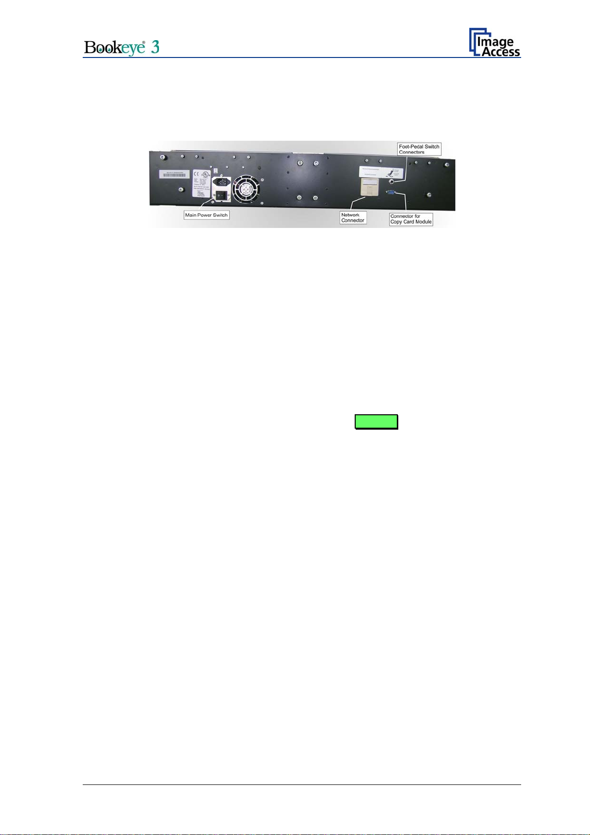
A.2.2 Connecting the Power Source
The power connector and the main power switch are located at the right side of the back
of the document bed.
Picture 2: Bookeye® 3 scanner back side view
Important: Before connecting to the power source, check the following items:
The wall outlet is in perfect condition and properly grounded.
The power cable is not damaged in any way.
The wall outlet fuse has the correct electrical dimensions. Refer to the technical
specification chart for detailed information.
Check the device fuse. Use only the specified device fuse. The device fuse specification is
named on the identification plate.
After the main power switch is turned on, the green START field above the START
button lights up. This indicates that the BOOKEYE Color is ready-to-use.
A.2.3 Connecting the Network
The BOOKEYE Color scanner is delivered with a cross-over cable (green cable
connectors) and a standard CAT6 network cable.
The network connector is located at the back side of the document bed.
Use the cross-over cable to connect the BOOKEYE Color scanner directly to a PC via a
network card.
Use the network cable to connect the BOOKEYE Color scanner to a network.
A.2.4 Connecting a Foot Pedal Switch
The scan sequence and other operations can be invoked through the optional available
foot pedal switches.
At the back side of the device, there are two jack plugs to which the foot pedal switches
can be connected. The jack plugs are labeled with “FS1” and “FS2”.
Operation Manual Page 15
Page 16
A
A.3 Starting the Bookeye® 3 scanner
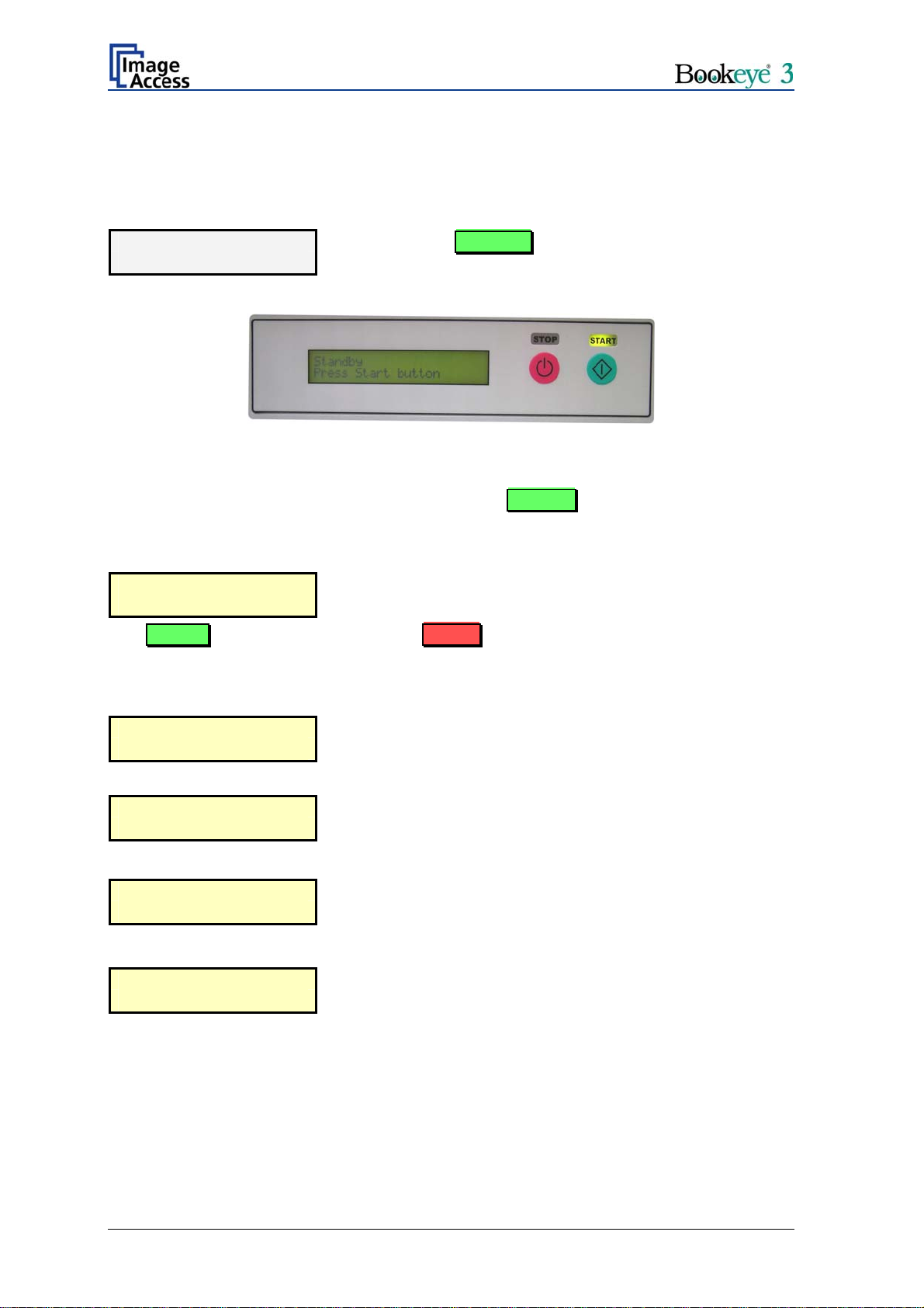
If the device has been used before and was constantly connected to power, the display
will show the message:
Standby
Press Start button
If the device was previously disconnected from the main power supply, the standby
message might not be visible. As long as the green START field above the Start button
is illuminated, the scanner can still be powered up by pressing the Start button.
Standby
Press Start button
The START field becomes dark and the STOP field will light up.
and the green START field above the Start button is
illuminated.
Picture 3: Display before power up
Press the Start button. The background light immediately
lights up indicating that the device is starting.
The next message in the display is:
System check
Please wait
followed by:
BE3-SCL-R1
Firmware 4.56
At this point during the power up cycle, the display will show:
RESET NETWORK
CONFIGURATION ?
If the Start button is pressed during this interval, the display shows:
RE YOU SURE ?
The message is indicated for some seconds. Meanwhile the
device performs the basic hardware and software checks.
This is the device name followed by
the firmware version
for one second.
If the Start button is pressed again in the next three seconds
the IP address, gateway and subnet mask are all reset to
their factory defaults.
Page 16 Operation Manual
Page 17
This procedure is followed by:
MECHANICS CHECK
192.168.1.50
If the tests end successful, the display shows:
HARDWARE CHECK
192.168.1.50
When the power-up test sequence is finished error free, the display shows the final
message.
Ready to scan
After the device has powered up, the Start button has a second function. It can be used to
delay a scan until the button is pressed in one of the application software scan modes.
Indicates, that the test for the motors and for the end position
switches is running. The second line shows the IP address.
Indicates the test of all remaining hardware components.
The second line shows the IP address.
A.3.1 Stopping the Bookeye® 3 scanner
If the Stop button is pressed at any time the scanner is idle, the display will at first show
the message:
Prepare to shut down
The message is displayed for two seconds before the device
is powered down .If the button is released before the time
has elapsed, nothing happens.
If the button is held the display reads:
Shut down in progress
At the end of the power down sequence the backlight turns off and the display reads:
Standby
Press Start button
Important: If for any reason the Bookeye® 3 scanner does not respond to the
application and the keyboard, the start key can power down the device,
regardless of the processor status. To achieve this, the start button must be
held for at least six seconds.
The device actually powers down. This is additionally
announced by the sound “Power down”.
Operation Manual Page 17
Page 18
A.4 Book Cradle
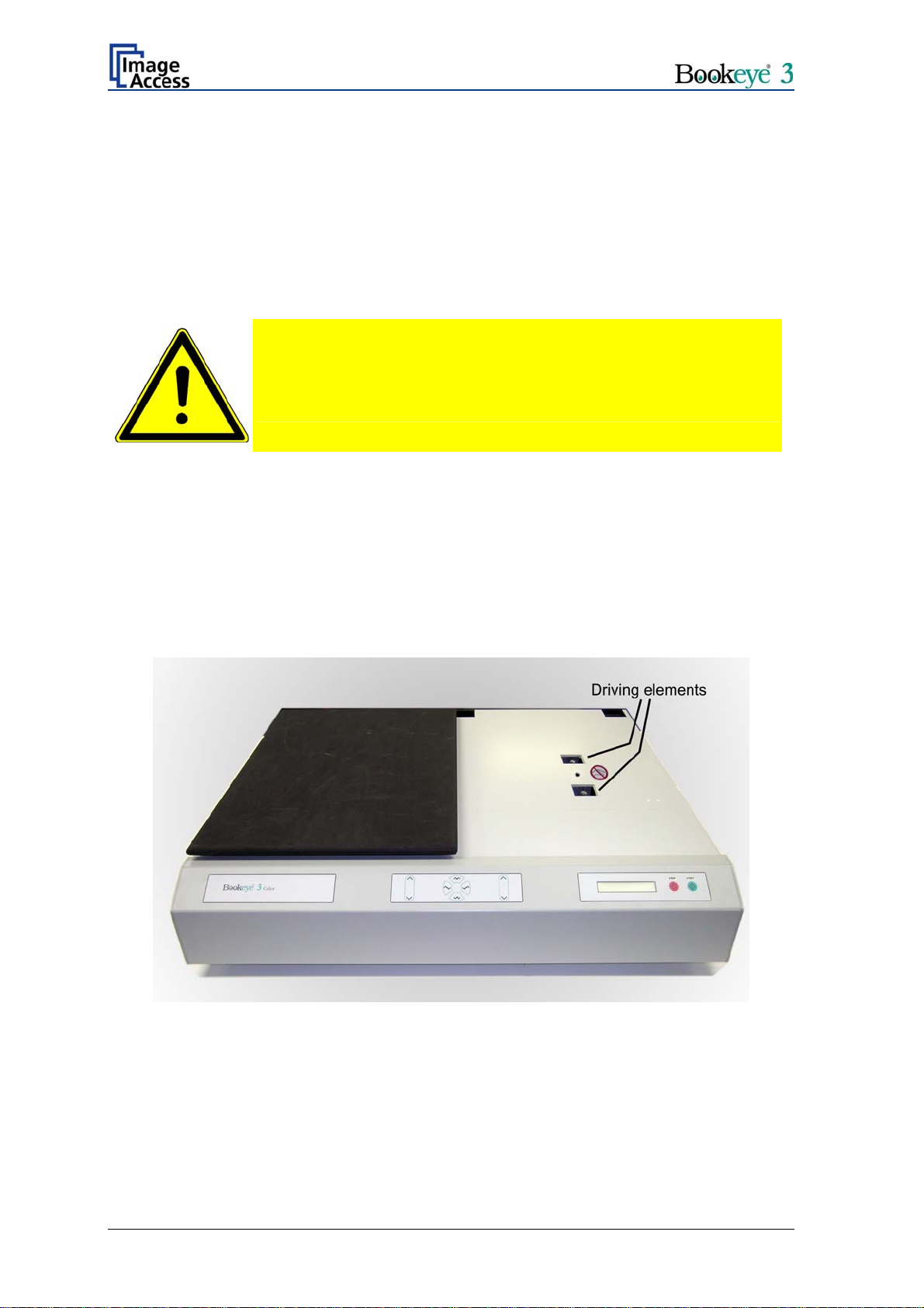
The motorized book cradle is safely and easily operated. Two driving elements on each
side move the wooden cradles plates upwards. The plates are not connected to the
stand-offs. If the book cradle is lowered and something blocks its way down, only the
weight of the plate and eventually part of the weight of a book will squeeze the object.
The driving element will only move if the appropriate key is pressed. For security reasons
there is no way of moving the book cradle automatically or remotely.
Safety Note!
Always lower the book cradle to its home position before power off.
Important: If the book cradle plates get dirty or scratched, use the micro fiber cleaning
cloth to clean the surface of the plates. The cleaning cloth should be slightly
damp.
A.4.1 Removing the Book Cradle Plates
Lift the two book cradle plates to separate them from the main body. They are not
fastened to the driving elements; they only rest on them.
Picture 4: Book cradle on right side removed
Page 18 Operation Manual
Page 19

A.4.2 Book Cradle Control Keys
Picture 5: Book cradle Control Keys
Operating one plate of the book cradle:
Left cradle up/down and/or Right cradle up/down
The control key on the outer side moves the corresponding
cradle up and down independently of the other cradle plate.
Operating both plates at the same time:
Cradles up
This key moves both plates upwards exactly in
synchronization.
Cradles down
This key moves both plates down exactly in synchronization.
Once a book has been balanced on the two book cradles, the compensator keys are used
to compensate between the two sides. That means, the surface of the book is at the same
height on both sides. The right compensator key operates identically on the right cradle.
Left compensator
The left compensator key lifts the left cradle and lowers the
right cradle at the same time.
Right compensator
The right compensator key lifts the right cradle and lowers the
left cradle at the same time.
Note: If the home position (lowest) of a cradle is reached, it stops automatically. An
acoustical click notifies the user of the fact that the end position is reached. If the
highest possible position is reached, it will also stop and generate the same click.
Operation Manual Page 19
Page 20
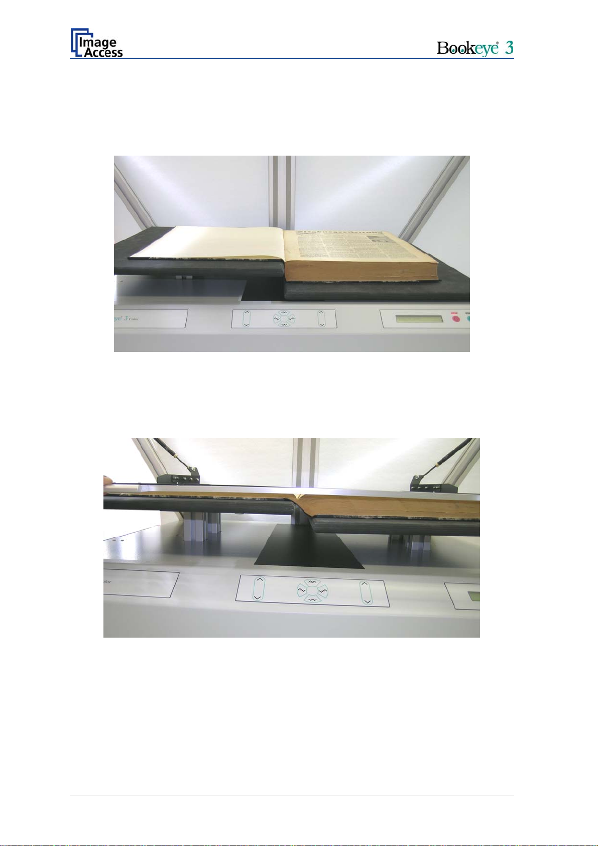
A.4.3 Operating the Book Cradle
First lower both cradles to their home position. Place a book on the right plate, open the
book cover and raise the left cradle until it fully supports the left book cover. This is the
reference position.
Picture 6: Book cradle at start
If the optional glass plate is used, lift both cradles up until they reach the glass plate. Use
only the Cradles up / Cradles down keys for this, as they keep the balance between the
cradles. Move up until the glass plate is exactly horizontal, while manually applying some
pressure on the book.
Picture 7: Book cradle at start with glass plate option
Page 20 Operation Manual
Page 21
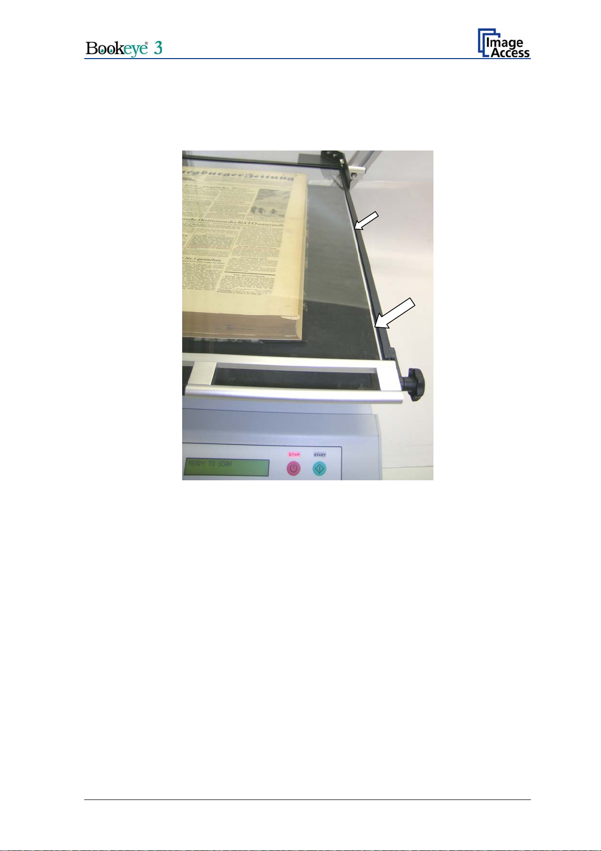
Note: Watch the small opening (see arrows in picture below) between the glass plate’s
frame and the cradle. If the distance is equal on the upper and lower side, the
glass plate is in the horizontal position.
Picture 8: Horizontal alignment check
Operation Manual Page 21
Page 22
After the reference position is reached, use only the left and right compensation keys
while advancing through the book.
This will ensure that the distance of the book’s surface stays constant through the entire
process and will therefore guarantee exactly the same resolution and size on all pages.
Picture 9: Book cradle in the middle of the book
Page 22 Operation Manual
Page 23

B Software Operation
B.1 The Integrated User Interface
Essentially, the scanner is a web server and comes with its own HTML based user
interface. To access a Scan2Net scanner, any standard web browser can be utilized.
Start your browser.
Enter the IP address of the scanner. The default IP address of the scanner: 192.168.1.50
The following start screen of the integrated user interface will be displayed.
Picture 10: Start screen
Click the button Launch Scan Application .
Operation Manual Page 23
Page 24

B.1.1 The Main Screen
After launching the scan application, the main screen of the integrated user interface will
open.
Picture 11: Main screen
The main screen is structured in three parts.
The menu bar of the large frame on the upper right part has five menu items:
¾ Options
¾ Properties
¾ Camera
¾ Settings
¾ Format
Page 24 Operation Manual
Page 25

The seven control buttons in the lower part of the screen control the output modes.
As default the output mode
Show is selected. After clicking onto the button Preview or
onto the button Scan Now a window opens and shows the image.
When selecting
Save the scanned image will not be displayed. Instead of the second
window a box opens where the desired directory can be set.
Selecting
Print will display the scanned image in a second window and direct the scanned
image to locally available printers.
Selecting
Selecting
Selecting
Selecting
Copy prints directly to a previously installed network printer.
FTP Upload scans directly a FTP server.
Mail sends the scanned image directly to a previously defined e-mail address.
Network uploads the scanned image directly to a previously defined workstation
in the network.
The frame on the left side shows the buttons for preview scan and main scan.
Note: Pressing the red button
switches the scanner off.
If the red button is pressed, the following window will appear.
Operation Manual Page 25
Page 26

B.1.2 The Options Screen
Picture 12: Options screen
The Document Mode allows the user to select between different types of documents:
Flat Mode the document is treated as flat, i.e. with a fixed focus setting, regardless
In
of the actual shape of the document. This mode avoids out of focus problems when
scanning three dimensional objects that cannot be described as folders or books.
In the
scanner advances from left to right or right to left. Also all geometric distortions are
compensated. It is essential that the book is aligned straight to the laser line for optimal
results. More details of the book fold correction can be specified in the
(see chapter B.1.2.1).
In the
independent of each other. It is essential that the open folder is aligned straight to the
laser line to get optimal results.
In the
(see chapter B.1.2.2).
In the
closed position.
Book Fold Correction mode the focus follows the surface of a book while the
(Options) dialog
Folder Mode the focus is fixed on the right side and the left side of the document
Fixed Focus Mode the focus is fixed to the value stored in the (Options) settings
Glass Plate Mode the focus is fixed to the defined height of the glass plate in
Page 26 Operation Manual
Page 27

The Scan Mode allows the user to select between High Quality with a reduced scanning
speed or Fast with normal speed.
The
Image Rotation can be any degree of rotation out of 90°, 180°, 270° or none. The
angle is defined in the clockwise direction.
Preview Scale value sets the size of the preview image. If set to Auto the function
The
will perform a best fit before the image is displayed on the screen.
The
Preview Quality [%] sets the JPEG quality of the preview image.
Embedded ICC switch is either Yes or No.
The
The
Embedded Metadata switch is either Yes or No. More details can be specified in the
(Options) dialog.
B.1.2.1 Book Fold Options
Picture 13: Book Fold Option screen
Clicking on
(Options) opens an additional window.
It allows to set the value for the margins, the left
and the right center position as well as the
threshold value.
The unit of measurement is “mil”. This unit of
measurement is defined as 1000 mil = 1 inch.
The
Surface Properties slider allows to modify
the correction of different surfaces from matte to
glossy.
The
Retouch Bookfold switch is either auto,
manual or off. If auto is selected, the width of the
bookfold area will be detected automatically and
filled. If manual is selected the sliders for
Left Center Position and Right Center Position
define the width of the filled area.
The
Retouch Pattern switch is either auto, black
or white. If auto is selected the pattern matches
with the pattern in the bookfold area, otherwise it
is black or white.
Operation Manual Page 27
Page 28

B.1.2.2 Fixed Focus Mode
If
Fixed Focus Mode is selected, the scanner
only focuses on one position.
The height above the base plate of this position
is controlled by the user via the menu on the left.
Move the slider or enter the value directly in the
field on the right.
The unit of measurement is “mil”. This unit of
measurement is defined as 1000 mil = 1 inch.
Picture 14: Book Fold Option screen
Page 28 Operation Manual
Page 29

B.1.2.3 Embedded Meta Data
This function is used in conjunction with the file
formats JPEG, TIFF or PDF.
It will allow the operator to include a set of
XMP/RDF compliant document metadata in the
file header.
Select Yes or No. Go to
set of XMP/RDF compliant metadata. The
configuration window will pop up.
Picture 15: Metadata screen
Metadata Description
(Options) to define a
Author Enter the name or organization that created the document
or is the copyright owner of the document.
Title Enter a short title for the scanned document.
Subject Abstract of the document.
Copyright Marker Select if the scanned document is copyright protected.
Copyright Information Enter the copyright message. This message will be only
embedded in the scanned document if the copyright marker
is set to “yes”.
URL of extended Copyright
Information
Keywords
(comma separated list)
Enter an external URL which shows a detailed copyright
message.
Enter a list of comma separated keywords which describe
the content of the document.
Note: Each change of an entry field is transferred to the scanner immediately.
Operation Manual Page 29
Page 30

B.1.3 The Properties Screen
Picture 16: Properties screen
The Color Mode control allows the user to select from a list the desired color modes.
Available are 24bit Color and 8bit Color as well as Grayscale, Line Art and Photo.
The
File Format control defines the file format that is used to store a scanned image.
Some interdependencies exist between the
control. For example, it is not possible to store an image scanned in True Color mode in
TIFF G4 file format.
The
JPEG Quality [%] control determines the compromise between quality and
compression rate. A higher quality factor produces larger files. The default setting of 75 is
a good compromise for most documents.
File Format control and the Color Mode
Page 30 Operation Manual
Page 31

The Format control selects between various standard paper formats. If Auto is selected,
the scanner scans the maximum format and then crops the document to its real size. This
function is highly advanced and works with default values most of the time.
The Auto function can also be statically configured with the two sliders
Auto Density and
Additional Margin on the right side.
If User is selected the
User defined format control opens. It allows to
set the values for Height and Width of the area to be scanned. It also
allows to define the position of the area to be scanned. The position is set
by the values for X Offset and Y Offset.
Note: The point of origin for X Offset and Y-Offset is defined in the upper left corner of
the document area. Only positive values are allowed.
Picture 17: X- and Y Offset definition
A value for Additional Margin can be added to or taken away from the image. It is
defined in units of pixels.
The
Auto Density value defines the brightness level of the background. All areas that are
darker are considered background and will be used to find the borders of the document.
The
Splitting Image button allows splitting the image into two pages although only one
scan is performed.
Operation Manual Page 31
Page 32

B.1.4 The Camera Screen
Picture 18: Camera screen
In this screen all parameters concerning the camera will be set.
Some interdependencies exist between controls displayed in this screen and settings in
other screens. The
selected.
Despeckle control e.g. is only displayed if the color mode Line Art is
Page 32 Operation Manual
Page 33

Picture 19: DPI mode Fixed
If the button DPI Mode is at Fixed, the resolution can be selected out of a drop down list
Resolution field.
in the
The values for
Resolution can be 150, 200, 300, 400 and 600 DPI and also True DPI.
True DPI is used if the scanner’s real resolution, depending on thickness of the document
as well as the position of the book cradles, should be used. The scanner will then
measure the optical resolution and use this in the file header.
Operation Manual Page 33
Page 34

Picture 20:DPI mode Flexible
If the button DPI Mode is set to Flexible, the resolution can be selected out of a drop
down list right to the
Resolution field.
This value can be manually overridden. Enter the desired resolution in the field left from
the drop down list field. The value can be varied in steps of 1 dpi. To send the new value
to the scanner, click on another menu item or press the “Tab” key or the “Enter” key on
your PC keyboard.
If the
Resolution field value is changed, the right box will show user defined.
The
Brightness slider defines the brightness of the resulting image. Lower brightness
values make the image darker.
The
Contrast slider defines the contrast of the resulting image. Higher contrast values
show more details. If scanning in binary (i.e. Line Art, Photo Mode), the behavior of the
contrast slider changes. If the
the If the
Auto Threshold is on, the contrast slider defines the reaction time of the
Auto Threshold is off, the slider has no function at all. If
automatic background tracker.
Note: Use the contrast slider carefully in the automatic threshold mode because if set to
the extremes, unexpected image artifacts occur.
Image Sharpness slider invokes an advanced algorithm which sharpens the image
The
according to the local content of a given area.
Page 34 Operation Manual
Page 35

The Exposure function sets the threshold value for the black cut function or for the auto
exposure function.
Picture 21: Black Threshold slider
No disables the exposure function.
When Black Cut or Auto is selected an additional slider is displayed.
Black Cut
0 (zero) to 100
Sets the threshold for black. All pixel values found in the image below
the selected value are set to black.
Result: The image contrast is improved.
Auto
0 (zero) to 100
Sets the threshold for black and activates the automatic exposure
control.
This function searches the image for the highest and the lowest pixel
value. The highest pixel value is defined as “white”. Is the lowest pixel
value higher than the threshold it is defined as “black”. Otherwise all
values below the threshold are defined as “black”.
Result: Automatic contrast control and the image contrast is improved.
Note: The
Exposure function is not displayed in the color modes Line Art and Photo.
Operation Manual Page 35
Page 36

The Gamma slider does the gamma correction directly inside the camera electronics.
Picture 22: Gamma slider with preselection buttons
Three typical values are predefined on the Preselection buttons.
The
Color Gain drop down list changes the gain on a specific channel. This function is
used to eliminate any color shift or tints from the background.
Picture 23: Color Gain screen
Note: The Color Gain controls are only displayed in color modes 24bit Color and
8Bit Color.
Page 36 Operation Manual
Page 37

B.1.5 The Settings Screen
Picture 24: Settings screen
This screen allows the user to set some secondary parameters.
This screen allows the user to set
some secondary parameters.
Language Selector offers a drop
The
down list of languages for the
scanner’s user interface.
Currently available languages are
english, deutsch, français, and
russian. If russian is selected, all
text are displayed in Cyrillic fonts.
The S2N user interface shows all
texts in the selected language
immediately after switching.
Picture 25: List of available languages
Operation Manual Page 37
Page 38

The Skin Selector offers different
surfaces (skins) for the user interface.
Currently available surfaces are
modern and application, metal and
classic, classic-green and classic-
light. Other skins can be designed
and integrated by the user.
Picture 26: Skin Selector
Tool Tips can be activated to inform
the user with short texts about the
available functions in each screen.
With the drop down list the delay time
can be defined. Selecting No Tool
Tips switch this function off.
Picture 27: Tool Tips
Show Status Window turns on and off the display of a scanner status window. Click the
Yes button to activate this window.
Picture 28: Status window
Use IES opens an additional window to show the demo mode of the Image
Enhancement System. The IES allows to modify specific scan parameters.
Page 38 Operation Manual
Page 39

B.1.6 The Format Screen
Picture 29: Format screen
When selecting this screen the image scanned and displayed at last is shown. The
dimension of the image depends on the selected format in the Properties screen.
The Preview (Maximum) button allows to rescans the complete document
area. The image will be displayed in the preview area of the Format screen.
The Preview button rescans the document area which is set in the
Properties screen. To get a new preview scan, first change to the
Properties screen, set the new format, and finally return to the Format
screen. Click on the Preview button to display the new image.
Operation Manual Page 39
Page 40

To select a specific area of the image, click with the mouse in the preview area and drag a
rectangle. Dragging with the mouse the rectangle starts in the upper left corner and ends
in the lower right corner.
Click the Zoom in button to display the selected area of the image in detail.
Î
Picture 30: Rectangle dragged with mouse
Picture 31: "Zoom in" result
Click the Zoom out button to return to the previous dimension of the image.
Click the Get Clip button to get the selected area of the image in full resolution
in a separate window.
The control fields X Offset and Y Offset allow the user to position the rectangle.
The control fields Width and Height allow the user to set the dimension for the rectangle
of the specific area.
The control field Unit allows the user to select from a list the unit of measurement for the
specification of the rectangle.
The control field Clip Size offers a list of formats for the specific area. The content of the
list depends on the size of the preview scan area. I.e. the smaller the preview scan area,
the shorter the list of available formats.
Page 40 Operation Manual
Page 41

B.1.7 Output Options
There are various output options available on a Scan2Net scanner. In most cases, the
button
Show is activated.
Picture 32:Output Option Show
A scan will open a new browser window and display the image on the screen. The output
options described in this chapter are accessible via the above menu but are also present
in the upper part of each scanned image.
Picture 33: Output Options in Scan Window
Their functionality is identical, therefore only the output option screen is described here.
Operation Manual Page 41
Page 42

B.1.7.1 Output Option Save
This output option scans to the local disk drive. After the scan is performed, a window
opens and the default file name is shown.
The user can select local and network drives for the save location and can also change
the file name before it is actually stored.
The Options key below the Save button is used to
define some parameters for the file name of the
image.
The Wildcard characters key below the file name
gives additional information concerning the
parameters of the file name.
Picture 34: Image output option
The Metadata key allows the user to define some
information which will be added to each file header.
Picture 35: Metadata mask
Page 42 Operation Manual
Page 43

B.1.7.2 Output Option Print
This output option prints to the locally available printers. After the scan is executed, the
standard windows printer interface is opened. The user can select one of the locally
available printers.
Picture 36: Output Option Print
Picture 37: Available List of Printers for Option Print
Operation Manual Page 43
Page 44

B.1.7.3 Output Option Copy
This output option prints directly to a previously installed network printer. The Option
is used to configure the remotely connected printer.
key
Picture 38: Output Option Copy
Remote Printer Description
Printer Preset Choose a printer configuration out of five possible sets of
parameters. If you click on “Change Name” you can change
the name of this set.
Connection Type Choose between IP Networking and SMB Printer Queue.
Address (with IP Networking
only)
Port (9100) (with IP Networking
only)
Connection Timeout (with
IP Networking only)
Port (139) (with SMB Printer
Queue only)
Server Authentication (with
SMB Printer Queue only)
Enter the IP address of the printer.
Enter the IP port of the remote printer. Default is port 9100.
Choose the timeout for connecting to the remote printer
before the connection is aborted.
Enter the IP port of the remote printer. Default is port 139
Select Yes or No
Page 44 Operation Manual
Page 45

Remote Printer Description
SMB Path
Queue only)
(with SMB Printer
Login (with SMB Printer Queue
only)
Enter the path of the directory where the printer is
established.
Enter the login for the printer if Server Authentication is set
to Yes.
Password Enter the password for the printer if Server Authentication
is set to Yes.
Data Format Choose the data format of the remote printer. Selectable
are Postscript, Postscript with framing HP/PJL
communication and HP DesignJet (HP/RTL) compliant
printers. Changing the data format will change some of the
options in this configuration window.
Data Compression Select the compression method if the printer type offers it.
Resolution Select the printing resolution. If an exact 1:1 copy of the
scanned document is required, the scanning resolution and
printing resolution must match.
Paper Format (not with all
printer types)
Choose the paper format for output.
Duplex Print Switch on/off printing both sides of a paper sheet (duplex).
Paper Feed Select the paper feed method for the remote printer. The
menu may contain manual paper feed, various paper trays
and paper rolls.
Copies Number of copies of each print
Printing Enhancement
Quality Level
(only DesignJet) Toggle the printing quality from draft to high quality.
Only available with HP/RTL compliant remote printers.
ICC Profile Select the profile used for printing. One can upload a set of
printer ICC profiles in the Poweruser setup.
Only available with HP/RTL compliant remote printers.
Color Matching Select the color rendering method for the remote printer.
Best Fit: The printer uses the nearest matching colors of
its own color space.
Printer Color Range: The printer uses the full range of its
color space despite of the color definition of the scanned
document.
Only available in conjunction with HP/PJL communication
framework.
Edge Anti Aliasing Switch on/off printer featured edge anti aliasing.
Only available in conjunction with HP/PJL communication
framework.
Note: Each change of an entry field is transferred to the scanner immediately.
Operation Manual Page 45
Page 46

Printing Enhancement
Brightness Modify the brightness level of the print.
Only available with HP/RTL compliant remote printers.
Contrast Modify the contrast level of the print.
Only available with HP/RTL compliant remote printers.
Gamma Modify the printer gamma.
Only available with HP/RTL compliant remote printers.
Note: Each change of an entry field is transferred to the scanner immediately.
Page 46 Operation Manual
Page 47

B.1.7.4 Output Option FTP Upload
The scanner can directly scan to a FTP server.
Picture 39: Output Option FTP Upload
The Option key is used to configure the FTP interface. A configuration window will pop
up.
FTP Upload Description
Address Enter the IP address of the remote FTP server.
Port (21) Enter the IP port of the remote FTP server.
Default is port 21.
Server Authentication Select the authentication method.
Login Enter the login name.
Password Enter the password for the login at the remote FTP server. The
password is stored using encryption.
Upload Path Enter the upload path at the remote FTP server, starting with /
(root). Click on the icon, to browse the directory structure of the
remote FTP server. Note: You must have a valid login for
browsing the directory structure.
File name prefix Enter the file name prefix. A time stamp will be added to this
prefix to form the complete file name.
Continued on the following page.
Operation Manual Page 47
Page 48

FTP Upload Description
Use a FTP Proxy ? Switch on/off the use of an FTP proxy for connecting to a remote
FTP server outside the local network.
FTP Proxy Address
(if “Use FTP Proxy” is set to
“Yes”)
Port
(if “Use FTP Proxy” is set to
“Yes”)
Specify the IP address of the FTP proxy.
Specify the IP port of the FTP proxy.
Note: Each change of an entry field is transferred to the scanner immediately.
Page 48 Operation Manual
Page 49

B.1.7.5 Output Option Mail
The scanner can directly e-mail each scan.
Picture 40: Output Option Mail
The Option key is used to configure the mail interface. A configuration window will pop
up.
Mail Upload Description
Transaction mode Choose if all scanned documents will be send to the same
receiver (automatic batch mode) or if the scanner should
ask after every scan (interactive).
Address Enter the IP address of the outgoing mail (SMTP/LMTP)
server.
Port (25) Enter the IP Port of the outgoing mail server.
Default: Port 25.
Server Authentication Set to YES if the mail server requires an authentication.
Login Enter the user name for authentication at the outgoing mail
server.
Password Enter the password for authentication at the outgoing mail
server. The password is stored using encryption.
Continued on the following page.
Operation Manual Page 49
Page 50

Mail Upload Description
Protocol Choose the connection protocol. SMTP is the most
common protocol.
Connection Timeout Choose the timeout for connecting to the outgoing mail
server before the connection is aborted.
File name prefix Enter the file name prefix. A time stamp will be added to
this prefix to form the complete file name.
Recipient Type in the recipient of the e-Mail.
Format: fully qualified e-Mail address.
Sender Type in the sender of the e-Mail.
Format: fully qualified e-Mail address.
Mail Subject Type in the e-Mail subject. (Optional)
Reply To Type in a reply address for answers. (Optional)
Format: fully qualified e-Mail address.
Force disposition
notification?
Request for a notification when the recipient has opened
the mail. Note: This feature is not supported by all mail
servers or clients.
Note: Each change of an entry field is transferred to the scanner immediately.
Page 50 Operation Manual
Page 51

B.1.7.6 Output Option Network
SMB is a network protocol which is used by Microsoft windows based networks.
Picture 41: Output Option Network
The Option key is used to configure the SMB Upload interface. A configuration window
will pop up.
SMB Configuration Description
Port (139) Enter the IP port of the SMB network communication. Default is
port 139.
Server Authentication Set to YES if the mail server requires an authentication.
Login Enter the user name for the login at the Windows workstation or
file server which you want to connect to.
Password Enter the password for the login at the Windows workstation or
file server which you want to connect to. The password is stored
using encryption.
SMB Path Enter the upload path at the Windows workstation, starting with
a single / (root). If you click at the icon you can browse the
workstation/server list and the directory structure of the
Windows workstation/file server. Note: You must have a valid
login for browsing the directory structure.
File name prefix Enter the file name prefix. A time stamp will be added to this
prefix to form the complete file name.
Operation Manual Page 51
Page 52

B.1.8 The Setup Screen
Although most settings on the system level can be performed only in the Poweruser
access level, some user defined settings are available on the start screen. The User
access level also allows showing certain information about the system like power up time,
remaining lamp life time or firmware version.
Start your browser and enter the IP address of the scanner to get access to the scanner.
The start screen (see Picture 10) will open.
On the start screen click the button Setup Device .
The next screen shows the login levels User, Poweruser and Admin.
Picture 42: Login screen
Page 52 Operation Manual
Page 53

Click the button User .
Picture 43: User screen
The user screen is divided into two sections.
The section Information shows some details of the scanner and gives a general
operation information.
The section User Settings allows the user to define some basic parameters of the
scanner.
Operation Manual Page 53
Page 54

In the section Information click the button Device Info and the following list will be
displayed.
Specific information can be reached by clicking the links below the headline Device Info
or by scrolling through the list.
Picture 44: Device Info screen
The tables following the keyword show the current status of the Bookeye® 3 scanner.
The most important information for users is the firmware version in the second table.
Other information may be of interest if a service technician is onsite or the hotline is
called.
To return to the USER screen (Picture 43) scroll down completely and click the button
Back to Main Menu or click on the “Return” button in your browser.
Page 54 Operation Manual
Page 55

In the section Information the button Operation Info opens the following list.
It shows various scan counters and elapsed time described in the following table.
Picture 45: Operation Info screen
Field Description
Total Scan Count The total number of scans performed since the scanner left
the factory. Each CCD scan cycle is counted, regardless of
it being a pre-scan or a full scan.
Total Power Up Cycles The total number of power up cycles performed since the
scanner left the factory. This function counts the start/stop
button invoked cycles only.
Total Operating Time The total operating time since the scanner left the factory.
This is the on-time only, standby time does not count.
Lamp Operating Time The total lamp operating time since the scanner left the
factory. This is the on-time including the dimmed periods.
Remaining Lamp Operating
Time
The typical remaining life time of the lamps. The
Bookeye® 3 scanner life time is so long, that the lamps
usually last for the life time of the device.
To return to the USER screen (Picture 43) scroll down completely and click the button
Back to Main Menu or click on the “Return” button in your browser.
Operation Manual Page 55
Page 56

In the section User Settings click the button User Settings and the following screen will
be displayed.
Picture 46: User Settings screen
The Bookeye® 3 scanner is Energy Star compliant. In stand-by mode it consumes only
5W of power. The Energy Star guidelines require the default time until the device goes
into standby to be 15 minutes.
Use the function Energy Star Power down to set the time until the scanner goes into
stand-by mode.
The user can modify the standby time by selecting a time period from the list. Picture 46
shows the list of available values. The list starts with 5 minutes and ends with four hours.
This is the maximum time period defined through the Energy Star guidelines.
Select the desired time from the list.
Page 56 Operation Manual
Page 57

Picture 47: Volume level
Click the button Volume to set the loudspeakers volume of the scanner.
A screen opens and shows a graphic to symbolize the volume.
Click on the percentage value to change the volume level. The color of the graphic will
change depending on the selected volume level.
Volume level Volume bar color
Up to 30% Green
40% to 60% Yellow
70% or higher Red
Operation Manual Page 57
Page 58

Picture 48: Foot pedal settings
The scanner has two connectors on its back to connect foot pedals. For each foot pedal a
specific action can be defined.
Click the button Foot Pedal. Go to the left or right pedal drop-down list and select which
action to take if the corresponding pedal is operated.
Drop-down list item Function
Start scan Starts the scan with the selected scan area size
Start scan A3L left page/right page Starts the scan in ISO A3 landscape format at the
left / right side of the document area.
Start scan A4L left page/right page Starts the scan in ISO A4 landscape format at the
left / right side of the document area.
Page 58 Operation Manual
Page 59

Picture 49: Splitting Start Page
In some languages, books are printed from right to left. In these cases, it can be desirable
to start the page splitting in the reverse order, i.e. starting with the right side followed by
the left side in the second step.
Click the button Splitting Start Page and select either the left page or the right page as
start page.
Operation Manual Page 59
Page 60

B.2 Laser guided Document Type Detection
This chapter is important to understand because it describes the most common scanning
problems and their cure.
The Bookeye® 3 scanner has an auto focus system that actually stays in focus as the
scanner sweeps from left to right over the scanning area. To achieve this, the pre scan
must be able to capture the heights profile of the document. This is pretty simple while
scanning a flat surface but becomes challenging if scanning a thick book.
The height profile is also necessary to move the light beams across the scanning area.
The two lamps and the line CCD form an electronic gear. Details are described in the
Setup and Assembly Manual.
The gear is adjusted at the home position (lowest position) during the setup process. If the
height of the document is known at a given position, the lamps can compensate for with a
change in the angle relative to the scanning position and therefore guarantee the best
possible illumination.
The scanner also has a built in digital zoom. As the document gets closer to the scanning
head the digital zoom is adjusted accordingly to keep the resolution and document size
independent of its heights.
B.2.1.1 Description of the Laser Purposes
The Bookeye® 3 scanner comes with a built-in line laser that serves five different
purposes.
— During the setup procedure, the laser line helps to check the mounting position of the
camera head. This is described in the Setup and Assembly Manual.
— The laser line is used to guide the user in positioning the document. The document
should be positioned somewhere on the book cradle plates, oriented toward the
center of the scanner. The laser line must cross the document preferably in an area
that is not too dark.
— The user should align the document content in respect to the laser line. The automatic
format detection will crop the document to a rectangular size but it cannot compensate
for any skew.
Picture 50: Correct versa incorrect placement
Page 60 Operation Manual
Page 61

— The area where the laser line covers the outer edges of the document is the only
area, where the optional thumb removal function will work. The user should hold down
the book only in these areas.
Picture 51: Holding down a book
— The scanner performs a pre-scan to detect size, elevation and location of the
document. The pre-scan function uses the laser to adjust the focus in the following
scan.
Operation Manual Page 61
Page 62

B.2.2 Scanning in Fixed Focus Mode
This is the simplest scanning mode. The focus is fixed to a known position that the user
can change. See chapter B.1.2.2 for detailed description.
If the glass plate option is installed, this value is overridden and replaced with the autofocus value measured during the installation of the glass plate option.
Not only the focus but also the lamps follow the virtual height of the document regardless
of its real value. The scanner will not perform any pre-scan.
The digital zoom is adjusted for the predefined height, either from the “Fixed Focus Mode
Settings” or the glass plate option; in such a way that the previously selected resolution is
reached. If true dpi resolution is selected, the digital zoom is off and the scan will be
made in the native optical resolution at the given distance between the document and the
CCD.
B.2.3 Scanning in Flat Mode
This is also a simple scanning mode. The scanner performs a pre-scan and measures the
height of the document. If the measurement does not produce any meaningful results, the
keyboard will play the sound “Attention” and will display the message:
No focus found
Retry? N= Stop Y=Start
Use left cradle pos.?
N= Stop Y=Start
The focal point and the lamps will follow the measured height of the document, which was
determined during pre-scan.
The digital zoom is adjusted relative to the measured height so that the previously
selected resolution is met. If true dpi resolution is selected, the digital zoom is switched
off and the scan will be executed in the native optical resolution at the given distance
between the document and the CCD.
Note: As long as the scan is not cancelled, all retries or changes of the document mode
are completely transparent to the application. If the scan is finally cancelled, a
“Stop Button Pressed” status is sent to the application.
After repositioning the document, press Start to retry or Stop
to cancel and advance to the next step.
The highest book cradle position is assumed to be the focal
plane. Press Start to accept or Stop to cancel the scan.
Page 62 Operation Manual
Page 63

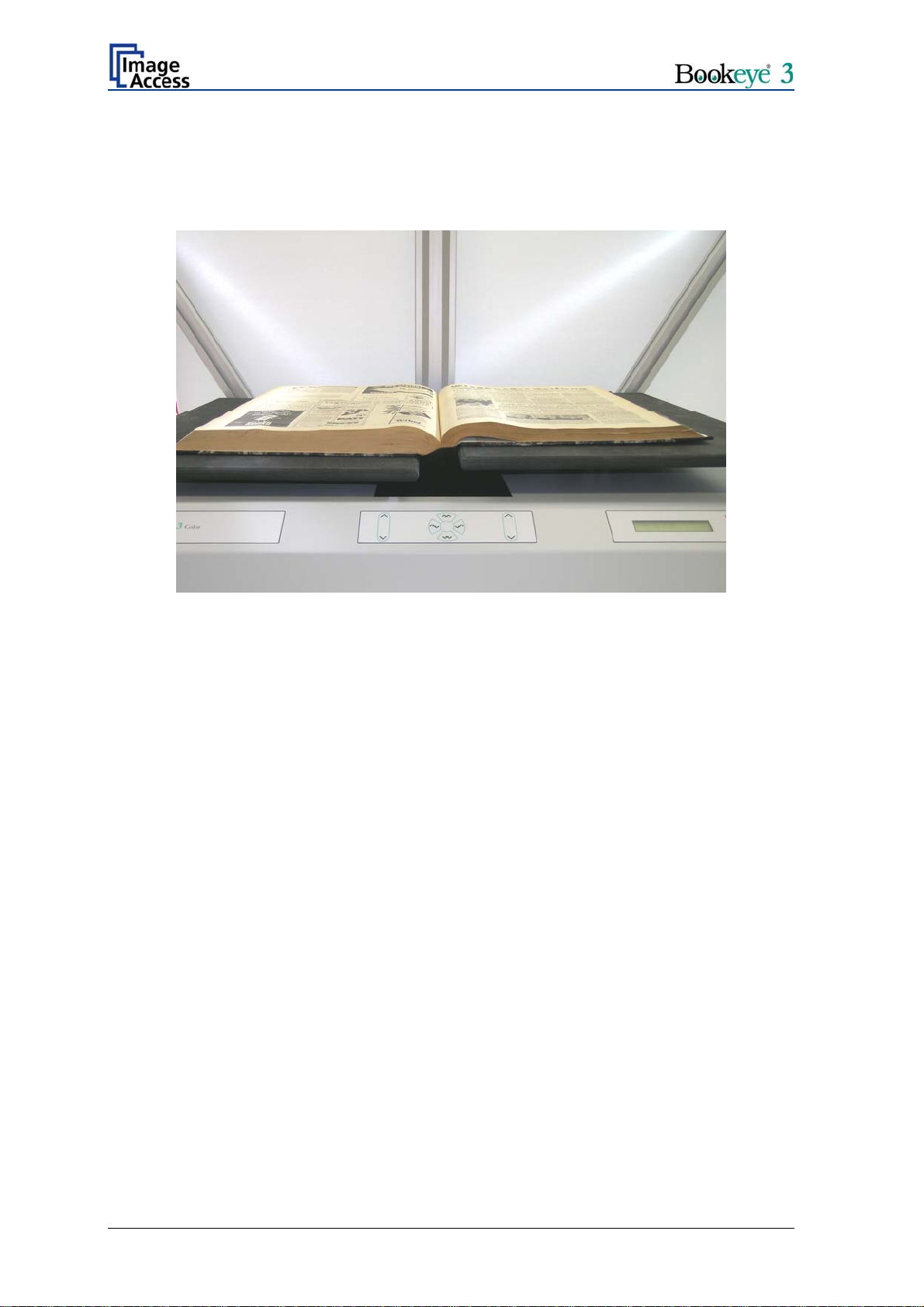
B.2.4 Scanning in Folder Mode
This mode is similar to the flat mode, but it treats both sides of the document bed
independently. The scanner performs a pre-scan and measures the heights of the
document on the left side and the right side.
Picture 52: Scanning in folder mode
If the measurement does not produce any meaningful results the keyboard will play the
sound “Attention” and the display will show the message:
No focus found
Retry? N= Stop Y=Start
Use cradle positions?
N= Stop Y=Start
The focal point and the lamps will follow the measured heights of the two sides of the
document which was determined during pre-scan. The focus plane and the position of the
lamps make a step between the two different levels in the middle of the scanner. It is
therefore necessary to center a folder to the scanner to achieve optimum results.
The digital zoom is adjusted relatively to the measured height so that the previously
selected resolution is met. If true dpi resolution is selected, the digital zoom is switched
off and the scan will be executed in the native optical resolution at the given distance
between the document and the CCD.
Note: This will result in two different dimensioned images if they are not at the same
height.
Note: As long as the scan is not cancelled, all retries or changes of document mode are
completely transparent to the application. If the scan is finally cancelled, a “Stop
Button Pressed” status is sent to the application.
After repositioning the document, press Start to retry or Stop
to cancel and advance to the next step.
The left and right book cradle positions are assumed to be
the focal plane. Press Start to accept or Stop to cancel the
scan.
Operation Manual Page 63
Page 64

B.2.5 Scanning in Book Mode
The scanner measures the height profile as it advances over the scanning bed in the
pre-scan. The profile of a book has some typical characteristics that the scanner attempts
to find. One of these is the book fold, which the scanner will find and use later for further
compensation.
If the book is positioned so that the laser covers it fully and the background in the vicinity
of the laser is not too dark, the curvature of the book will be found and the scanner will
adjust focus, lamps and digital zoom to produce a perfectly flat image with the predefined
resolution. The optional true dpi resolution in book mode reduces the image to the
resolution at the home position (lowest) of the scanner.
If the measurement of the curvature does not produce sufficient results to identify the
book fold, the sound “Attention” will be played and the display will show the message:
No book fold found.
Retry? N= Stop Y=Start
Use folder mode?
N= Stop Y=Start
If the results of the measurement are still not sufficient, the keyboard will again play the
sound “Attention” and the display will show the message:
No focus found
Retry? N= Stop Y=Start
Use cradle positions?
N= Stop Y=Start
Note: As long as the scan is not cancelled, all retries or changes of document mode are
completely transparent to the application. If the scan is finally cancelled, a “Stop
Button Pressed” status is sent to the application.
After repositioning the document, press Start to retry or Stop
to cancel and advance to the next step.
The scanner temporarily uses the folder mode. Press Start
to accept or Stop to cancel the scan.
After repositioning the document, press Start to retry or Stop
to cancel and advance to the next step.
The left and right book cradle positions are assumed to be
the focal plane. Press Start to accept or Stop to cancel the
scan.
Page 64 Operation Manual
Page 65

C Tests and Troubleshooting
C.1 Troubleshooting Matrix
Fields with light blue background need the power user access level. All other fields are
available to all users.
Problem Possible cause Action
Green start button does not
light up.
Start button does not power
up the device.
Stop button does not power
down the device.
Image is darker than
expected.
Image is brighter than
expected.
Image is darker on one side
than on the other side.
No power Check main outlet, power cord, power-
on switch on the back of the device.
Connector failure, software
glitch …
Internal software hangs,
application hangs …
The target used for white
balance is much brighter
than the scanning target.
The target is much brighter
than the target used for
white balance.
The electronics gear is out
of sync.
Switch power off for at least 10
seconds. Retry after green start button
lights up again.
End all applications and retry. If
problem persists, press the start
button for at least 10 seconds. Power
up again.
Go to the White Balance function
and modify the Brightness Correction
setting.
Go to the White Balance function
and modify the Brightness Correction
setting.
Exercise the Scan Start procedure.
Image shows a color shift
towards red (tint)
Image shows a color shift
towards blue (tint)
Image shows a color shift
towards red (tint)
Image shows areas that are
overexposed and too bright.
Operation Manual Page 65
The target used for white
balance is bluer than the
scanning target.
The target used for white
balance is more red than
the scanning target.
The scanner receives
significant amounts of
infrared light (sun or spot
lights) not visible to the
human eye.
The scanner receives too
much ambient light from a
point source like sunlight,
spotlight etc.
Go to the RGB adjustments and lower
the gain on red.
Go to the RGB adjustments and lower
the gain on blue.
Change position, close blinds, dim or
shut off any bright spotlights.
Change position, close blinds, dim or
shut off any bright spotlights.
Page 66

Problem Possible cause Action
Image has unevenly spaced
vertical stripes or streaks.
Image has evenly spaced
vertical stripes or streaks.
Image has horizontal stripes
or streaks.
Scanning two A4 (letter)
pages perfectly centered in
A3 (double letter) format
cuts of one side of the scan.
A small portion of the lower
side of the target is missing
in the image.
The image shows an extra
small portion on the lower
side of the target
The electronics gear is out
of sync.
50/60Hz interference from
fluorescent ceiling lights.
Improper white balance.
The scanner’s optical
middle (in the horizontal
direction) is lost or
misaligned.
The scanner’s optical
center (in the vertical
direction) is lost or
misaligned.
The scanner’s optical
center (in the vertical
direction) is lost or
misaligned.
Exercise the Scan Start procedure.
Change position, dim or shut off some
lamps, change ceiling lights to
electronic ballasts.
Exercise the White Balance
procedure.
Exercise the Scan Start procedure.
Go to the Scan Center function and
lower the value.
Go to the Scan Center function and
raise the value.
The image is out of focus on
a flat target with significant
contrast, book cradles in
their lowest position and flat
mode scanning.
The reference focal point
is lost or misaligned.
Exercise the Autofocus procedure.
Page 66 Operation Manual
Page 67

D Technical Data
D.1 Scanner Specifications
Scan Area
Maximum Scan Area [pixel] 10640 x 7441 pixels
Maximum Scan Area [mm] 900 x 630 mm
Optical Resolution 300 x 400 dpi
Resolution 75 – 400 dpi
Luminosity
Scanning 4500 LUX
Stand-by (300 sec): 1000 LUX
Stand-by, idle 0 LUX (lamps off)
Lamps:
High Power White LED UV- and IR-radiation free
Lifetime 50.000 hours on-time
Book Cradle:
Maximum load / book cradle plate 15 kg / 33 lbs
D.2 Ambient Conditions
Operating Temperature +5 to +40° Celsius
Storage Temperature 0 to +60° Celsius
Relative Humidity 20 to 80% (non-condensing)
Ambient luminance ≥ 300 Lux
Noise Level < 50 dB(A) (Operating)
< 30 dB(A) (Stand-by)
Operation Manual Page 67
Page 68

D.3 Electrical Specifications
This device is Energy Star compliant.
Voltage 110–240 VAC
Frequency 50/60 Hz
Power Consumption
Standby 6 W
Self-test mode 150 W
Start procedure 260 W
Standby, operational, lamps off 105 W
Standby, operational, lamps on 140 W
Operating 275 W
Pre-Scan 170 W
Moving the book cradle (lamps on)
Both plates simultaneously 165 W
Single plate 150 W
Moving the book cradle (lamps off)
Both plates simultaneously 130 W
Single plate 115 W
Page 68 Operation Manual
Page 69

D.4 Dimensions and Weight
Scanner outer dimensions (without lamps) 1250 x 900 x 780 mm (H x W x D)
49,2 x 35,4 x 30,7 inches
Scanner outer dimensions (lamps attached) 1250 x 1500 x 780 mm (H x W x D)
49,2 x 59,0 x 30,7 inches
Total weight of scanner (without glass plate),
ready to use
Dimensions Transport Box
(contains main body, camera head in separate
box, lamps, camera neck, test target folder,
assembly material, tools and cables)
Weight Transport Box: 55,5 kg / 122,1 lbs
Weight of camera head box: 17 kg / 37,4 lbs
Total shipping weight 137,5 kg / 302,5 lbs
65 kg / 143 lbs
600 x 1520 x 1100 mm (H x W x D)
23,6 x 59,8 x 43,3 inches
Operation Manual Page 69
Page 70

D.5 CE Declaration of Conformity
The undersigned, representing the manufacturer:
Image Access GmbH
Hatzfelderstrasse 161 – 163
42281 Wuppertal, Germany
herewith declares that the
Product: Bookeye Planetary Scanners
Model Designation: BE3-AAA-BCd-XXX
with AAA = SCL or SGS or CGS
B = R or N
C = 1 or 2 or 3 (
representing the size of the scan area)
d = + or not applicable
XXX = 12-digit serial number
Serial number: All
For unique identification of the product configuration, please submit the 12-digit serial number found on the
product to the manufacturer.
Is in conformity with the following European standards and IEC directives:
EMC:
EMC Directive 89/336/EEC with amending directives 92/31/EEC & 93/68/EEC as per
EN 55022 Class B
EN 55024
EN 61000-3-2
EN 61000-3-3
Safety:
Low Voltage Directive (Safety) 73/23/EEC as per
EN 60950(A1/A2/A3/A4/A11)
UL 60950
Wuppertal, 25.02.2008
Thomas Ingendoh , President and CEO
Page 70 Operation Manual
Page 71

D.6 FCC Declaration of Conformity
Responsible party:
Image Access GmbH
Hatzfelderstrasse 161 – 163
42281 Wuppertal, Germany
Product: Bookeye Planetary Scanners
Model Designation: BE3-AAA-BCd-XXX
with AAA = SCL or SGS or CGS
B = R or N
C = 1 or 2 or 3 (
d = + or not applicable
XXX = 12-digit serial number
Serial number: All
For unique identification of the product configuration, please submit the 12-digit serial number found on the
product to the manufacturer.
representing the size of the scan area)
This device complies with Part 15, Class B of the FCC Rules. Operation of this
product is subject to the following two conditions: (1) This device may not cause
harmful interference, and (2) this device must accept any interference received,
including interference that may cause undesired operation.
D.7 Safety Declaration
Product: Bookeye Planetary Scanners
Model Designation: BE3-AAA-BCd-XXX
with AAA = SCL or SGS or CGS
B = R or N
C = 1 or 2 or 3 (
d = + or not applicable
XXX = 12-digit serial number
Serial number: All
For unique identification of the product configuration, please submit the 12-digit serial number found on the
product to the manufacturer.
This device complies with:
EN 60950 :2000
representing the size of the scan area)
UL 60950
CSA C22.2 No. 60950
Thomas Ingendoh , President and CEO
Operation Manual Page 71
Page 72

For your notes
Page 72 Operation Manual
 Loading...