

Page 1
Oppeerraattiioonn
O
Maannuuaall
M
This device is compliant.
Page 2

File: BE2-N3_OperationManual_I.doc
Page 3

2008 – 2010 by Image Access GmbH, Wuppertal, Germany
Printed in Germany. All rights reserved.
Reproduction in whole or in part in any form or medium without express written permission of
Image Access is prohibited. Scan2Net® is a registered trademark of Image Access. Other
designated brands herein are trademarks of Image Access.
All other trademarks are the property of their respective owners.
Image Access reserves the right to change the described products, the specification or
documents at any time without prior notice. For the most recent version, always check our web
site www.imageaccess.de
Operation Manual Page 3
or the customer service portal at http://service.imageaccess.de
Page 4

Introduction
Dear Customer,
We congratulate you on the acquisition of this innovative product from Image Access.
We at Image Access are proud of the work we do; it is the result of our extremely high
standards of production and stringent quality control.
With the Bookeye® scanner, Image Access offers an efficient scanner which covers a
wide scope of applications due to its versatility. Its integrated web based user interface
makes all functions available in structured menus.
This operation manual is designed to lead you through all situations which will arise when
using the Bookeye® scanner.
For this reason, we ask you to read the operation manual attentively before starting to
work with the device. By doing so, you will avoid operation errors and you can control all
functions from the beginning.
In addition please consider the following points:
Damages to your unit may have occurred during shipping. Please check for
damages immediately after delivery of the unit. Inform your supplier if damage has
occurred.
Read and ensure that you understand the safety notes. They were developed for
your protection and safety as well as to protect the unit.
Regular maintenance conserves the high quality and safety of the Bookeye®
scanner during the entire service life.
If you have any further questions, please feel free to contact your local dealer or
Image Access directly. Our staff will be happy to help you.
For your daily work with the Bookeye® scanner, we wish you success and complete
satisfaction.
Regards
Your Image Access Team
Page 4 Operation Manual
Page 5

About this Manual
Operation Manual
All information about the normal operation and behavior of this device is found in the
Operation Manual. The manual is written for people who only operate the device and do
not perform setup and adjustment procedures. All device elements and software functions
are described in detail, although some of them might never be used. This manual does
not cover any application software like BSW, BSCAN or BCS2. Refer to the appropriate
manual to learn about the application software.
Setup and Assembly Manual
The Setup and Assembly Manual is written for technical staff with some basic
mechanical as well as software skills. Many resellers will offer on-site installation;
therefore, large parts or all of the setup and assembly manual might not be of interest to
the reader. The access level at which these setup and adjustment processes are
performed is called “Power user”. This “Power user” level is password protected from
access by the normal operator.
All available manuals for this device can be downloaded from our customer service portal
at http://service.imageaccess.de
manuals.
The manual is divided into four sections, A to D.
Section A describes the hardware of the device. It shows the connectors as well as all
other elements of the device.
Section B describes the operation software and the keyboard functions.
Section C describes troubleshooting procedures and test scan generation.
Section D shows all technical data and declarations.
. Be sure to always check for the latest versions of these
Operation Manual Page 5
Page 6

Version History
Version Published in Content/Changes/Supplements
A March 2002 Preliminary version.
Description of the device.
Description of the integrated user interface, Vers.2.
B April 2002 Additional information concerning user interface, Vers.2.x
C May 2003 User interface complemented and revised. User defined formats
by Java
D July 2005 Some minor changes in the S2N user interface. Some menu item
has been deleted or moved. Additional information concerning
firmware update procedure.
E September 2005 New content in chapter 13, Updating Firmware.
F January 2007 Firmware 4.8x: Some modifications in S2N user interface.
Content in some menus have been changed, help function
available by clicking a “question mark” in the upper right corner of
the S2N screen.
G January 2008 Minor changes in order and numbering of sections in chapter A.1.
to A.3.4
H March 2008 Scan2Net Interface V5 implemented. Some new features and
screens. Some functions in new order.
I May 2009 Scan2Net Interface V5.20 implemented.
Content of some screens in the S2N user interface have been
changed. Some minor modifications in the list of available
parameters, e.g. formats of scan area.
Page 6 Operation Manual
Page 7

T
h
i
s
p
a
g
e
i
n
t
e
n
t
i
o
n
a
l
l
y
l
e
f
t
b
lla
n
k
T
h
i
s
p
a
g
e
i
n
t
e
n
t
i
o
n
a
l
l
y
l
e
f
t
T
h
i
s
p
a
g
e
i
n
t
e
n
t
i
o
n
a
l
l
y
l
e
f
t
b
n
k
b
l
aan
k
Operation Manual Page 7
Page 8

Table of Contents
Introduction--------------------------------------------------------------------------4
About this Manual -----------------------------------------------------------------5
Version History ---------------------------------------------------------------------6
A Hardware Operation -------------------------------------------------------- 14
A.1 Safety Notes ............................................................................................ 14
A.1.1 Marking of Safety Notes 14
A.2 Safety Precautions................................................................................... 15
A.3 Device Location ....................................................................................... 16
A.3.1 Environment 16
A.3.2 Ambient Light 17
A.3.3 Table 17
A.3.4 Power outlet 17
A.4 Device Overview ...................................................................................... 18
A.4.1 Connectors on the Rear Side 19
A.5 Establishing Connections......................................................................... 20
A.5.1 Connecting the Power Source 20
A.5.2 Connecting to the Network 20
A.5.3 Connecting Foot Pedal Switches 20
A.6 Starting the Bookeye® scanner ............................................................... 21
A.6.1 Switching off the Bookeye® scanner 23
Page 8 Operation Manual
Page 9

Table of Content, part 2
A.7 Keyboard ..................................................................................................24
A.7.1 FORMAT 25
A.7.2 TYPE 26
A.7.2.1 FLAT 26
A.7.2.2 BOOK 27
A.7.2.3 FOLDER 28
A.7.3 PAGES 29
A.7.4 COLOR 31
A.7.5 BRIGHTNESS 31
A.7.6 CONTRAST 32
A.7.7 COPIES 32
A.8 Set-up Mode .............................................................................................33
A.8.1 Activating the Set-up Mode 33
A.8.2 Checking the current settings 33
A.8.3 Setting new values 34
A.8.3.1 Special advice for the gateway address setting 34
A.8.4 Saving new values 34
A.8.5 Ending the Set-up Mode 34
Operation Manual Page 9
Page 10

Table of Content, part 3
Software Operation --------------------------------------------------------- 35
B
B.1 The Integrated User Interface .................................................................. 35
B.2 The Main Screen...................................................................................... 36
B.2.1 The Options Screen 38
B.2.1.1 Book Fold Options 40
B.2.1.2 Embedded Meta Data 41
B.2.2 The Properties Screen 42
B.2.3 The Camera Screen 44
B.2.3.1 Threshold Dynamic / Threshold fixed 48
B.2.3.2 Despeckle 48
B.2.4 The Settings Screen 49
B.2.5 The Format Screen 51
B.3 Output Options......................................................................................... 53
B.3.1 Output Option Save 54
B.3.2 Output Option Print 55
B.3.3 Output Option Copy 56
B.3.3.1 Remote Printer 56
B.3.3.2 Printing Enhancement 58
B.3.4 Output Option FTP Upload 59
B.3.4.1 FTP Server 59
B.3.5 Output Option Mail 61
B.3.5.1 Mail Server 61
B.3.6 Output Option Network 63
B.3.6.1 SMB Configuration 64
B.4 Information............................................................................................... 65
B.5 The Setup Screen .................................................................................... 66
B.5.1 Login Screen 66
B.5.2 Access Level User 67
B.5.2.1 Device Info Screen 68
B.5.2.2 Operation Info Screen 69
B.5.2.3 User Settings Screen 70
B.5.2.4 Energy Star power down 71
B.5.2.5 Foot Pedal 72
B.5.2.6 Start buttons 73
B.5.2.7 Splitting Start Page 74
B.5.3 Turning off the device 75
Page 10 Operation Manual
Page 11

Table of Content, part 4
Tests and Troubleshooting ---------------------------------------------- 76
C
C.1 Troubleshooting Matrix .............................................................................76
D Technical Data---------------------------------------------------------------- 78
D.1 Scanner Specifications .............................................................................78
D.2 Ambient Conditions...................................................................................78
D.3 Electrical Specifications ............................................................................79
D.4 Dimensions and Weight............................................................................79
D.5 CE Declaration of Conformity ...................................................................80
D.6 FCC Declaration of Conformity.................................................................81
D.7 Safety Declaration ....................................................................................81
Operation Manual Page 11
Page 12

Table of Pictures
Picture 1: Front side view .................................................................................................. 18
Picture 2: Details on the back side .................................................................................... 18
Picture 3: Connectors on rear side.................................................................................... 19
Picture 4: Display before power up ................................................................................... 21
Picture 5: Keyboard Bookeye® scanner ...........................................................................24
Picture 6: Function field FORMAT..................................................................................... 25
Picture 7: Reference with format definitions...................................................................... 25
Picture 8: Function field TYPE .......................................................................................... 26
Picture 9: Book fold positioned on center line ................................................................... 27
Picture 10: Example for document height ......................................................................... 27
Picture 11: Distance to document bed edge ..................................................................... 27
Picture 12: Example for document used with FOLDER .................................................... 28
Picture 13: Function field PAGES ..................................................................................... 29
Picture 14: Function field COLOR ..................................................................................... 31
Picture 15: Function field BRIGHTNESS .......................................................................... 31
Picture 16: Function field CONTRAST .............................................................................. 32
Picture 17: Function field COPIES .................................................................................... 32
Picture 18: Start screen..................................................................................................... 35
Picture 19: Main screen..................................................................................................... 36
Picture 20: Confirm shutdown ........................................................................................... 37
Picture 21: Options screen............................................................................................. 38
Picture 22: Book Fold Option screen................................................................................. 40
Picture 23: Metadata screen ............................................................................................. 41
Picture 24: Properties screen......................................................................................... 42
Picture 25: Camera screen ............................................................................................ 44
Picture 26: Color mode Binary .......................................................................................... 44
Picture 27: List of resolutions ............................................................................................ 45
Picture 28: Black Threshold slider..................................................................................... 46
Picture 29: Gamma slider with preselection buttons ......................................................... 47
Picture 30: Color Gain screen ........................................................................................... 47
Page 12 Operation Manual
Page 13

Table of Pictures, part 2
Picture 31: Threshold method selector..............................................................................48
Picture 32: Despeckle function ..........................................................................................48
Picture 33: Settings screen ............................................................................................ 49
Picture 34: List of available languages ..............................................................................49
Picture 35: Skin Selector ...................................................................................................50
Picture 36: Tool Tips..........................................................................................................50
Picture 37: Status window .................................................................................................50
Picture 38: Format screen ..............................................................................................51
Picture 39: Rectangle dragged with mouse .......................................................................52
Picture 40: "Zoom in" result ...............................................................................................52
Picture 41:Output Option Show .........................................................................................53
Picture 42: Output Options in Scan Window......................................................................53
Picture 43: Image output option.........................................................................................54
Picture 44: Metadata mask................................................................................................54
Picture 45: Output Option Print..........................................................................................55
Picture 46: Available List of Printers for Option Print.........................................................55
Picture 47: Output Option Copy.........................................................................................56
Picture 48: Output Option FTP Upload ..............................................................................59
Picture 49: Output Option Mail...........................................................................................61
Picture 50: Output Option Network ....................................................................................63
Picture 51: Information.......................................................................................................65
Picture 52: Login screen....................................................................................................66
Picture 53: User screen .....................................................................................................67
Picture 54: Device Info screen........................................................................................... 68
Picture 55: Operation Info screen......................................................................................69
Picture 56: Available user settings.....................................................................................70
Picture 57: Foot pedal settings ..........................................................................................72
Picture 58: Start button actions..........................................................................................73
Picture 59: Available actions..............................................................................................73
Picture 60: Splitting Start Page.......................................................................................... 74
Picture 61: Security query after shutdown command ........................................................75
Picture 62: Browser message after shutdown ...................................................................75
Operation Manual Page 13
Page 14

A Hardware Operation
A.1 Safety Notes
Read all safety notes thoroughly and ensure that you understand the safety notes.
The safety notes are introduced for your personal protection and for your safety.
All safety requirements of the following standards
EN 60950
UL 60950
CSA C22.2 No. 60950
are fulfilled by the Bookeye® scanner.
A.1.1 Marking of Safety Notes
All safety notes are marked with a warning sign.
A description of the potential hazard is found at the right side beside the warning sign.
Safety Note!
Text with description of potential hazard.
Page 14 Operation Manual
Page 15

A.2 Safety Precautions
Warning: Please read all the safety precautions before you operate the scanner.
Serious injury can occur to you or to others if you do not know how to use the
scanner safely.
Please follow the safety precautions in this manual exactly.
To prevent fire or shock hazard, do not expose this device to rain
or any type of moisture.
Follow all safety precautions to avoid personal injury or damage to the device.
1. Place the scanner in a clean, well-ventilated room. Do not operate the scanner in an
area with poor ventilation.
2. Openings in the scanner’s housing in the front or at the back are provided for air
circulation. Do not cover or block the openings.
3. Do not place the scanner near a heat or cold emitting source such as a space heater,
furnace, or air conditioning unit.
4. Do not place the scanner near any devices or electrical boxes emitting high voltage.
5. Always place the scanner on a flat and stable surface. The load bearing capacity of
the base must correspond to the device weight.
6. Do not lean on the scanner.
7. Do not place cups containing liquids or other such objects on the camera head or on
the document bed. If liquid spills into the scanner it can cause damage. If this occurs,
turn the scanner off, unplug the power cord from the wall receptacle and contact the
Image Access Technical Support.
8. Do not put any objects into any scanner housing openings unless specifically
instructed to do so by Image Access Technical Support.
9. Do not disassemble the scanner. If there is a need to disassemble the scanner, please
contact the Image Access Technical Support.
10. Do not use the scanner if it has been physically damaged. If this occurs, turn the
scanner off, unplug the power cord from the wall receptacle and contact the
Image Access Technical Support.
11. The scanner should be used only with the power cord that is supplied with the
scanner. If you are unsure, please contact the Image Access Technical Support.
12. Image Access recommends plugging the scanner into an appropriately-rated power
conditioner.
Operation Manual Page 15
Page 16
A.3 Device Location
A.3.1 Environment
Choose a location that complies with the limits of temperature and humidity. Refer to the
technical specification.
Note: Before using the BOOKEYE
one hour for temperature adaptation.
Temperature adaptation means:
A fast change from cold to warm environmental conditions can build up
condensation inside the housing. This will result in unfavorable scanned images
and could cause permanent damages to the unit.
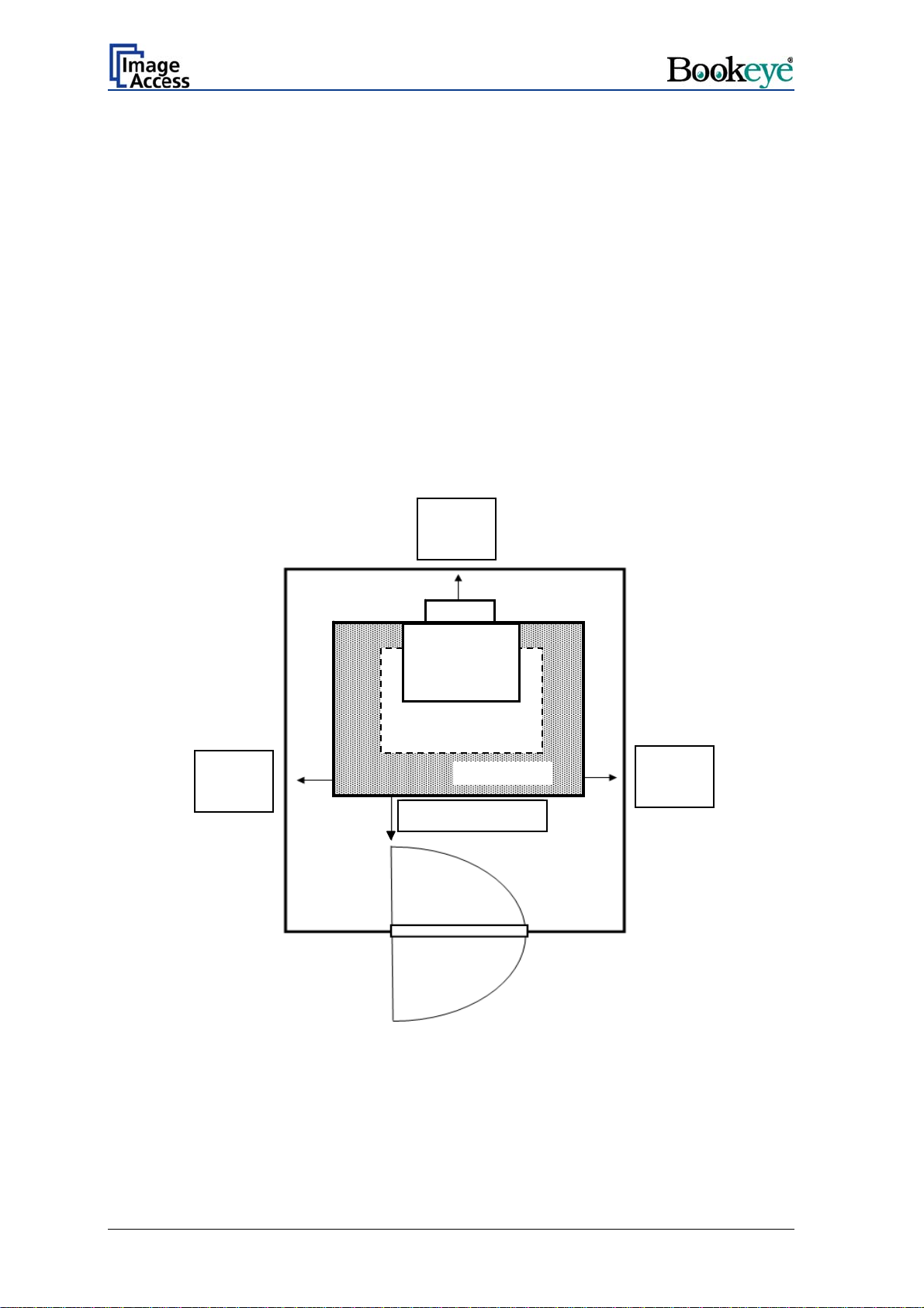
Please allow a minimum of 150 mm (6 inch) from any side walls and 300 mm (12 inch)
from a back wall. Leave one meter (3 feet) minimum distance from any door or entrance
way. Use illustration below as a guide.
®
scanner in the new environment allow at least
300 mm / 12 inch
Min. distance
Camera Head
Scan Media
150 mm / 6 inch
Min. distance
Do not operate the sca
nner in an area that has poor air circulation, and/or that is non-
ventilated.
Place the BOOKEYE
®
scanner on a flat and solid base. The load bearing capacity of the
base must correspond to the device weight.
Document Bed
1 m / 3 feet
150 mm / 6 inch
Min. distance
Page 16 Operation Manual
Page 17

A.3.2 Ambient Light
The location should have a controlled ambient light situation. Light scenarios to avoid are
direct sunlight, spot light from light beams, light sources that cause sharp shadows on the
scanning bed, high levels of ambient light and varying light conditions.
The Bookeye® scanner is an open system with a built-in high quality light source. Open
system means, that the ambient light is added to the light seen by the camera.
The recommended location for the Bookeye® scanner:
Is not exposed to daylight.
Is evenly illuminated from the ceiling with fluorescent lamps with electronic
ballasts. The light intensity measured on the book cradles should be approximately
300 lux.
The light should not cause any shadows; therefore the variation of the intensity
across the scan area should be kept below 20%.
If the fluorescent lamps are powered by non electronic ballasts, they will produce a flicker
twice the frequency of the main power supply (100Hz or 120Hz). If the intensity of this
light becomes too high, vertical stripes of even distances of approx. 8-12 pixels will be
visible on the scan.
Direct sunlight will vary over the day and will result in overexposed images. Sunlight also
can produce sharp shadows.
Light beams from spotlights will also produce sharp shadows. In most cases, they emit a
high level of infrared light. Infrared light is not visible to the human eye but to the camera.
The light source of the Bookeye® scanner itself has no infrared content at all. The
advantage is that the scanner does not have an image quality degrading infrared filter.
Too much infrared content will result in overexposure.
The Bookeye® scanner has an integrated “White Balance” function. This function will
compensate the ambient light influences. Therefore it is recommended to perform the
“White Balance” function when the ambient light scenario has been changed.
A.3.3 Table
Place the device on a flat and solid base, preferable a solid table. The load bearing
capacity of the table must correspond to the device weight. The table should be build to
hold at least three times the weight of the unit. Also it should not shake or move to avoid
image distortions. If the table is too weak it can be attached to a solid wall to stabilize it.
A.3.4 Power outlet
Safety Note!
Ensure that the power outlet is always accessible. This will help to
separate the device from the power outlet in case of an emergency.
Operation Manual Page 17
Page 18
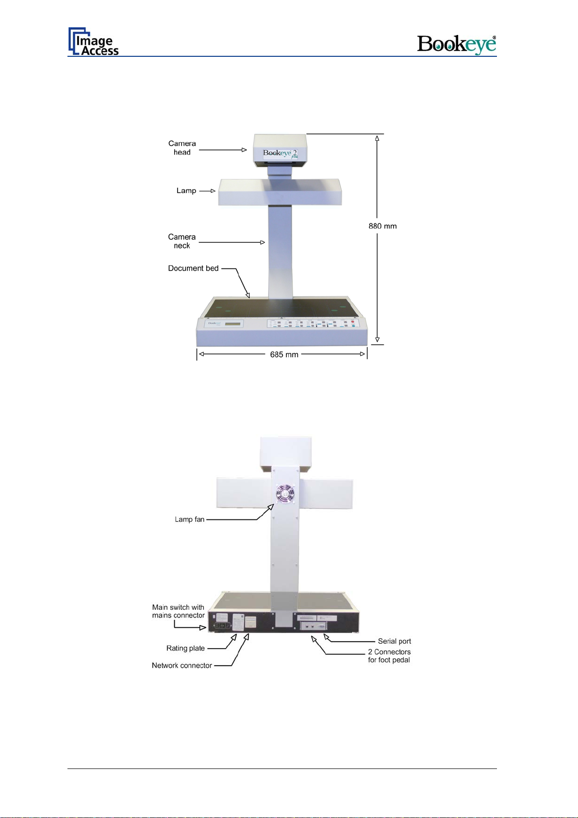
A.4 Device Overview
Picture 1: Front side view
For a first look at the Bookeye® scanner, some of the more important components have
been identified in the photos here. These components are referenced in the operation
manual.
Picture 2: Details on the back side
Page 18 Operation Manual
Page 19
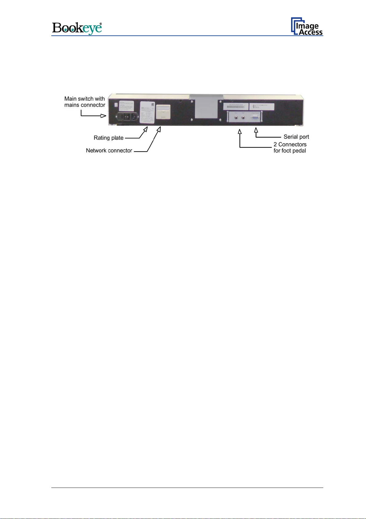
A.4.1 Connectors on the Rear Side
For easy orientation the connectors found on the rear side of the scanner are described in
the following picture.
Picture 3: Connectors on rear side
Operation Manual Page 19
Page 20

A.5 Establishing Connections
Important: Before connecting the Bookeye® scanner to the mains voltage, check the
following items:
The wall outlet is in perfect condition and properly grounded.
The power cable is undamaged.
The wall outlet is equipped with a correctly dimensioned fuse.
Turn the device off before plugging or unplugging any cable.
Connect the wall outlet and the power supply connector at the Bookeye® scanner with the
power cable.
A.5.1 Connecting the Power Source
The power connector and the main power switch are located at the right side of the back
of the document bed.
Important: Before connecting to the power source, check the following items:
The wall outlet is in perfect condition and properly grounded.
The power cable is not damaged in any way.
The wall outlet fuse has the correct electrical dimensions. Refer to the
technical specification chart for detailed information.
Check the device fuse. Use only the specified device fuse. The device fuse
specification is named on the identification plate.
After the main switch is turned on, the green START field above the START button lights
up. This indicates that the Bookeye® scanner is ready-to-use.
A.5.2 Connecting to the Network
The Bookeye® scanner is delivered with a cross-over cable (green cable connectors) and
a standard CAT6 network cable.
The network connector is located at the back side of the document bed.
Use the cross-over cable to connect the Bookeye® scanner directly to a PC via a network
card.
Use the network cable to connect the Bookeye® scanner to a network.
A.5.3 Connecting Foot Pedal Switches
The scan sequence and other operations can be invoked through the optional available
foot pedal switches.
At the back side of the device, there are two jack plugs to which the foot pedal switches
can be connected. The jack plugs are labeled with “FS1” and “FS2”.
Page 20 Operation Manual
Page 21
y
y
A
A.6 Starting the Bookeye® scanner
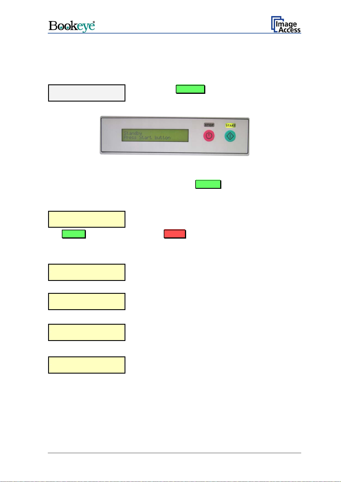
If the device has been used before and was constantly connected to power, the display
will show the message:
Standby
Press Start button
If the device was previously disconnected from the main power supply, the standby
message might not be visible. As long as the green START field above the Start button
is illuminated, the scanner can still be powered up by pressing the Start button.
Standb
Press Start button
The START field becomes dark and the STOP field will light up.
and the green START field above the Start button is
illuminated.
Picture 4: Display before power up
Press the Start button. The background lig
lights up indicating that the device is starting.
ht immediately
The next message in the display is:
stem check
S
Please wait
followed by:
BE2-SGS-N3
Firmware 5.00
At this point during the power up cycle, the display will show:
RESET NETWORK
CONFIGURATION ?
If the Start button is pre
RE YOU SURE ?
The message is indicate
device performs the basic hardware and software checks.
This is t
the firmware
for one seco
ssed during this interval, the display shows:
If the Start button is pre
the IP address, gateway and subnet mask are all reset to
their factory defaults.
he device name followed by
version
nd.
d for some seconds. Meanwhile the
ssed again in the next three seconds
Operation Manual Page 21
Page 22
y
This procedure is followed by:
MECHANICS CHECK
192.168.1.50
If the tests e
nd successful, the display shows:
HARDWARE CHECK
192.168.1.50
Indicates, that the test for the motors and for the end position
switches is running. The second line shows the IP address.
Indicates th
The second
e test of all remaining hardware components.
line shows the IP address.
When the power-up test sequence is finished error free, the display shows the final
message.
Read
to scan
The Bookeye® scanner
is now ready to use. On the keyboard, the following LEDs are
illuminated:
Function field LED
FORMAT A3
TYPE FLAT
PAGES LEFT
COLOR
BRIGHTNESS
COLOR
AUTO
CONTRAST AUTO
COPIES
1
After the device has po
wered up, the Start button has a second function. It can be used to
delay a scan until the button is pressed in one of the application software scan modes.
Page 22 Operation Manual
Page 23

A.6.1 Switching off the Bookeye® scanner
Press and hold the Stop button for at least three seconds.
The red STOP LED starts blinking.
The lamps and all LEDs on the keyboard will be switched off.
During the shutdown sequence the display shows
System Shutdown
Please wait
At the end of the shutdown sequence only the green LED above the Start button remains
on.
The Bookeye® scanner is now in stand-by mode.
Important: If for any reason the Bookeye® scanner does not respond to the application
and the keyboard, the start key can power down the device, regardless of
the processor status.
To achieve this, the start button must be held for at least six seconds.
Operation Manual Page 23
Page 24

A.7 Keyboard
Picture 5: Keyboard Bookeye® scanner
The keyboard is laid out in seven function fields. At each function field, upward/downward
buttons are used to select the desired setting.
The selected setting is displayed by LEDs at each function field.
The Start button and the Stop button control several functions. The function of these
buttons is defined by the mode of operation of the Bookeye® scanner.
The Bookeye® scanner has two modes of operation.
— Scan mode: In this mode of operation the Bookeye® scanner is controlled by
the function fields or by the integrated user interface.
Pressing the Start button starts the scan sequence with the
defined parameters. During the scan sequence the display shows
the current status.
A brief push of the Stop button interrupts the scan sequence. All
scanned data is lost.
Pressing the Stop button for at least three seconds switches the
Bookeye® scanner off. While switching off, the red LED blinks.
During this time the display shows the current status.
At the end of the shutdown sequence, the green LED above the
Start button lights up. The Bookeye® scanner now is in stand-by
mode.
— Set-up mode: In this mode of operation all specific device parameters of the
Bookeye® scanner are set.
For this purpose, five function fields of the keyboard are used.
Detailed information about the setting of device parameters can be
found in chapter A.8.
Page 24 Operation Manual
Page 25
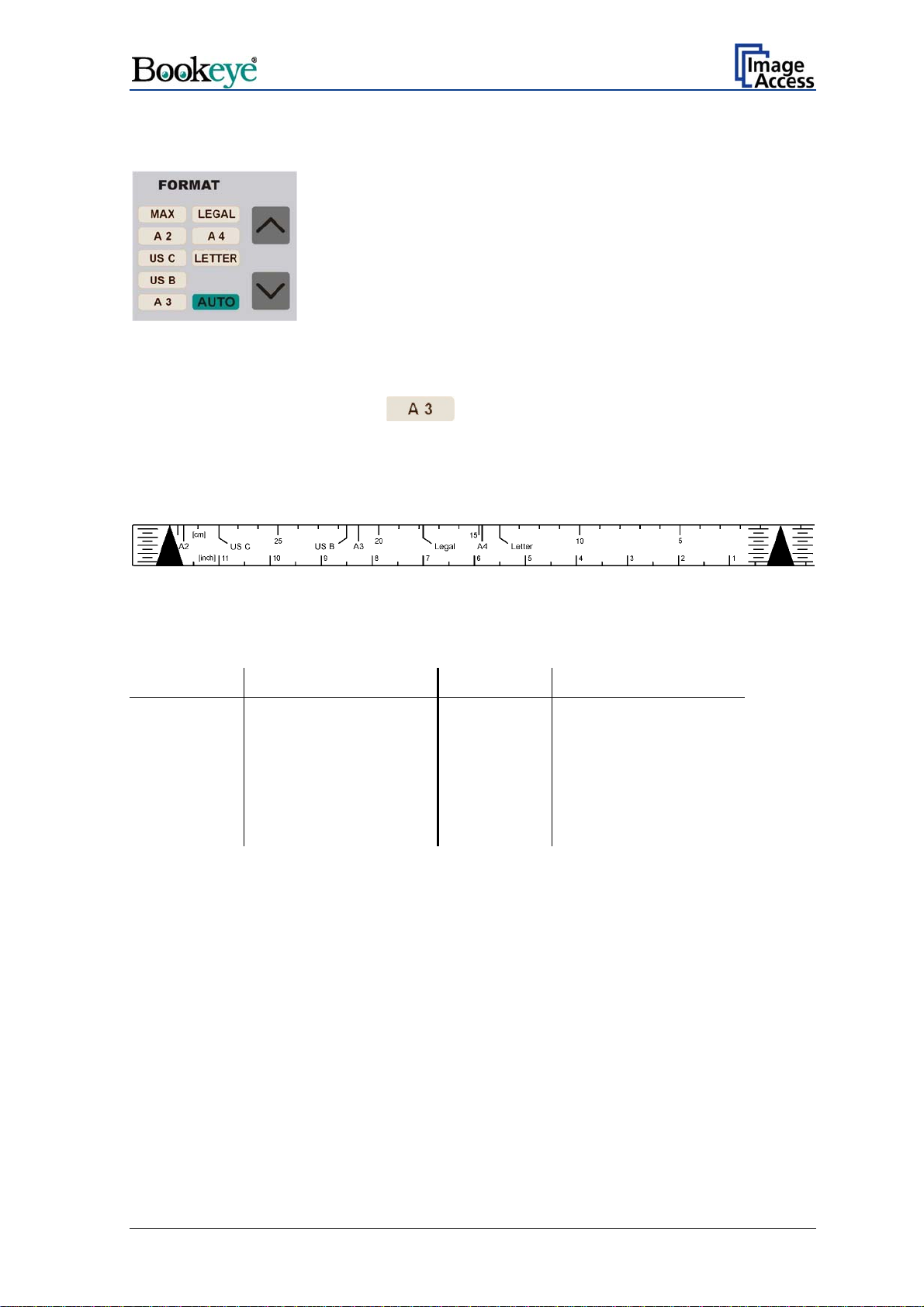
A.7.1 FORMAT
Picture 6: Function field FORMAT
The function field FORMAT defines the size of the scanned area.
field lights up. At the end of the system-test the
The size, indicated by the LED, always refers to the horizontal format. For easy orientation
above the keyboard, a format reference can be found. The available formats are marked
on this reference.
All formats defined on the reference are center symmetric.
Picture 7: Reference with format definitions
Table 1 indicates the dimensions of the scanned area.
Lettering Size Lettering Size
MAX Maximum scan area LEGAL 215,9 x 355,6 mm
A2 420 x 594 mm A4 210 x 297 mm
US C 431,8 x 558,8 mm LETTER 215,9 x 279,4 mm
US B 249,4 x 431,8 mm
A3 297 x 420 mm AUTO Automatic size detection
Table 1: Size of the scanned area
The AUTO setting activates the automatic size detection.
By using the AUTO setting, the Bookeye® scanner scans the complete, maximum scan
area. The size of the document which is placed on the document bed is recognized
automatically and displayed in the correct size.
Operation Manual Page 25
Page 26

A.7.2 TYPE
Picture 8: Function field TYPE
The function field TYPE defines the document type.
field lights up. At the end of the system-test the
Function Document type
FLAT Documents with consistent thickness, e.g. single pages.
Documents without binding or center fold.
BOOK Documents with a high center fold, e.g. books, catalogues or similar
things.
FOLDER Documents with distinct differences in level, e.g. opened files.
AUTO No function at this time.
A.7.2.1 FLAT
The type FL
thickness level over the whole document.
If the type FLAT is selected, the focus value is measured in a narrow range to the left,
next to the center line of the document bed. The distance to the center line results from
the size of the document to be scanned. Place the document at the edge of the document
bed and with at least a third of the document size left from the center line.
With the setting PAGES RIGHT, the focus value is measured right from the center line.
In this case, place the document so that at least a third of the document size is right of the
center line.
The distance between the measurement area and the center line depends on the selected
format. The smaller the selected format is, the closer the measuring area is to the center
line.
AT is suitable for all documents with a slight difference or no difference in
Page 26 Operation Manual
Page 27

A.7.2.2 BOOK
The type BOOK is suitable for bounded or stitched documents with a high center fold, the
so called “book fold”.
The setting BOOK activates the Book Fold Correction.
The following criteria must be met for proper functioning of the Book Fold Correction:
— The middle of the book fold must be positioned on the center line.
Picture 9: Book fold positioned on center line
— The document must not be positioned at the document bed edge. The distance
between document and document bed edge should be at least half of the document
height.
Picture 10: Example for document height
Picture 11: Distance to document bed edge
If these criteria are not met, the Bookeye® scanner produces an uncorrected image.
Operation Manual Page 27
Page 28

A.7.2.3 FOLDER
The type FOLDER is suitable for documents with plain differences in levels between left
and right page.
These are e.g. extensive files or documents without bound or center fold.
Picture 12: Example for document used with FOLDER
In combination with the setting PAGES BOTH, the left and right half of the document
are focused and sent separately.
Because of the separate focusing for each side, it is not necessary to take the documents
out of the file.
The second side is sent after further pushing the Start button or by clicking again the
buttons
Scan Now
Scan Preview Now
Or
in the integrated user interface.
Chapter B.1 describes the functions and the use of the integrated S2N user interface.
Page 28 Operation Manual
Page 29

A.7.3 PAGES
Picture 13: Function field PAGES
The function field PAGES defines the output mode.
field lights up. At the end of the system-test the
The settings LEFT, RIGHT and BOTH activate the page separation.
Function Output mode
SINGLE No page separation. Selected document size as one image.
LEFT Page separation activated. Output of the left half of the selected scan
area size.
RIGHT Page separation activated. Output of the right half of the selected scan
area size.
BOTH Page separation activated. Output of the left and right half of the
selected scan area size consecutively.
AUTO No function at this time.
Operation Manual Page 29
Page 30

Examples:
Selected setting
Example 1:
Function field FORMAT: A4.
Function field PAGES: SINGLE.
Example 2:
Function field FORMAT: A3.
Function field PAGES: LEFT
Scan area (white area)
Example 3:
Function field FORMAT: A3
Function field PAGES: RIGHT
Page 30 Operation Manual
Page 31

A.7.4 COLOR
Picture 14: Function field COLOR
The function field COLOR defines the color mode.
field lights up. At the end of the system-test the
Function Output mode
COLOR Scans the document in 24-bit color mode.
GRAY Scans the document in 8-bit gray scale mode.
PHOTO Scans the document in bi-tonal (black/white) mode combined with a
dithering effect. The readability of details in the scan is improved by the
dithering.
B & W Scans the document in bi-tonal (black/white) mode.
AUTO No function at this time.
A.7.5 BRIGHTNESS
Picture 15: Function field BRIGHTNESS
The function field BRIGHTNESS sets the brightness value while scanning.
field lights up. At the end of the system-test the
Moving the LED bar upwards increases the brightness.
Moving the LED bar downwards decreases the brightness.
Operation Manual Page 31
Page 32

A.7.6 CONTRAST
Picture 16: Function field CONTRAST
The function field CONTRAST sets the contrast value while scanning.
At the end of the system-test the
Moving the LED bar upwards increases the contrast value.
Moving the LED bar downwards decreases the contrast value.
field lights up.
A.7.7 COPIES
Picture 17: Function field COPIES
Note: This function field is only active in the copier version of the device.
field lights up. At the end of the system-test the
The function field COPIES selects the number of copies.
Page 32 Operation Manual
Page 33

A.8 Set-up Mode
In set-up mode, the user can set different parameters of the Bookeye® scanner.
A.8.1 Activating the Set-up Mode
The Bookeye® scanner must be off.
Press and hold the Stop button and then press the Start button.
The lamps light up and the display shows in two lines:
Self Test
KBD vers.
This message will be displayed until the end of the internal self-test sequence.
(version number)
During the internal self-test sequence, all LEDs on the keyboard light up consecutively
After the self-test is completed, the LEDs light up in the same position which was active
when the device was switched off.
The display now shows the serial number of the Bookeye® scanner in two lines.
.
A.8.2 Checking the current settings
To check the current settings of the IP address, the subnet mask, the gateway address
and DHCP value, perform the following steps.
Press the up / down buttons at the FORMAT keyboard field to select the displayed value.
Serial number of the device (e.g. BE2-SCL-N2)
Serial number of the device
IP:
AAA.BB
Subnet:
AAA.BBB.CCC.DDD
B.CCC.DDD
The display shows …
Gateway:
AAA.BBB.CCC.DDD
DHCP
YES / NO (displayed value depends on the current setting)
Operation Manual Page 33
Page 34

A.8.3 Setting new values
To set new values for the displayed parameters, use the following buttons:
— Use the up / down buttons at the function field TYPE to change the value for AAA as
well as to switch the setting for DHCP between YES and NO.
— Use the up / down buttons at the function field PAGES to change the BBB value.
— Use the up / down buttons at the function field COLOR to change the CCC value.
— Use the up / down buttons at the function field BRIGHTNESS to change the DDD
value.
Press the corresponding button to increase or decrease the desired value.
Press the button continuously to change the values fast upwards or downwards.
A.8.3.1 Special advice for the gateway address setting
If no gateway is used, use the same address as f
or the IP address setting.
A.8.4 Saving new values
Press and hold the Start button for at least one second to save the new value.
The display shows the following message.
Settings stored
Please reboot
After this message, the display returns to the serial number.
A.8.5 Ending the Set-up Mode
To end the set-up mode, press and hold the red Stop button for at least three seconds.
The red STOP LED starts blinking.
The display shows the message:
System Shutdown
Please wait
The lamps and all LEDs
After the power-down sequence is finished, only the green LED above the Start button
remains on.
Page 34 Operation Manual
on the keyboard will be switched off.
Page 35

B Software Operation
Essentially, the scanner is a web server and comes with its own HTML based user
interface. To access a Scan2Net scanner, any standard web browser can be utilized.
A basic requirement before using the integrated user interface is to configure the browser
as follows:
Force the browser to reload the page content every time directly from the scanner and
not to load from the cache memory.
Enter the scanner’s IP address in the exception list.
B.1 The Integrated User Interface
Start your browser.
Enter the IP address of the scanner. The default IP address of the scanner: 192.168.1.50
The following start screen of the integrated user interface will be displayed.
Picture 18: Start screen
Launch Scan Application switches to the main screen. Detailed information will be found
starting in chapter B.2.
Setup Device switches to the setup menu. Detailed information will be found starting in
chapter B.5.
Information gives a short summary of the device parameters. Information will be found
in chapter B.4.
Operation Manual Page 35
Page 36

B.2 The Main Screen
After launching the scan application, the main screen of the integrated user interface will
open. The main screen is structured in three parts. Switching between the sections is
done with a mouse click.
Picture 19: Main screen
1: The menu bar of the large frame on the upper right part has five menu items:
Options
Properties
Camera
Settings
Format
Page 36 Operation Manual
Page 37

2: The seven control buttons in the lower part of the screen control the output modes.
As default the output mode Show is selected. After clicking onto the button Preview
or onto the button Scan Now a window opens and shows the image.
When selecting Save the scanned image will not be displayed. Instead of the second
window a box opens where the desired directory can be set.
Selecting Print will display the scanned image in a second window and direct the
scanned image to locally available printers.
Selecting Copy prints directly to a previously installed network printer.
Selecting FTP Upload scans directly a FTP server.
Selecting Mail sends the scanned image directly to a previously defined e-mail
address.
Selecting Network uploads the scanned image directly to a previously defined
workstation in the network.
3: The frame on the left side shows the buttons for preview scan (Preview) and main
scan (Scan Now).
Pressing this button switches the scanner off.
If the red button is pressed, the following screen will appear.
Picture 20: Confirm shutdown
Click on the button Shutdown and the scanner switches off.
Operation Manual Page 37
Page 38

B.2.1 The Options Screen
Picture 21: Options screen
The Document Mode allows the user to select between different types of documents:
In Flat Mod e the document is treated as flat, i.e. with a fixed focus setting, regardless
of the actual shape of the document. This mode avoids out of focus problems when
scanning three dimensional objects that cannot be described as folders or books.
In the Book Fold Correction mode the focus follows the surface of a book while the
scanner advances from left to right or right to left. Also all geometric distortions are
compensated. It is essential that the book is positioned on the document bed as
described in chapter A.7.2.2.
More details of the book
fold correction can be specified in the (
Options) dialog (see
chapter B.2.1.1).
In the Folder Mode the f
ocus is fixed on the right side and the left side of the document
independent of each other. It is essential that the open folder is aligned straight to the
laser line to get optimal results.
Page 38 Operation Manual
Page 39

The Scan Mode allows the user to select between High Quality with a reduced scanning
speed or Fast with normal speed.
Image Rotation
Rotates the image before displaying.
The Image Rotation can be any degree of rotation out of 90°, 180°,
270° or none. The rotation angle is defined in clockwise direction.
Mirror
The image can be mirrored before displaying.
Click on the selection arrow and set the desired mirror axis.
Available are Horizontal or Vertical.
Select None to display the image without mirroring.
The Preview Scale value sets the size of the preview image. If set to Auto the function
will perform a best fit before the image is displayed on the screen.
The Preview Quality [%] sets the JPEG quality of the preview image.
The Embedded ICC Profiles switch is either Yes or No. If set to Yes an ICC profile is
embedded into every image after scanning.
Embedded Metadata
Select Yes to add metadata information to the image.
Clicking the Option link opens a window, where the
embedded metadata can be entered.
To close the option window click the button Close Window
Operation Manual Page 39
Page 40

B.2.1.1 Book Fold Options
Clicking on (Options) beside Book Fold Correction opens an additional window.
It allows to set the value for
the threshold value,
the top and the bottom margins,
the left and the right margins
the left and the right center position.
The unit of measurement is “mil”. This unit of
measurement is defined as 1000 mil = 1 inch.
The selected values for the margins will be
added to the image.
Picture 22: Book Fold Option screen
The sliders for Left Center Position and
Right Center Position define the width of the
area beside the detected book fold to be filled
in white color.
Page 40 Operation Manual
Page 41

B.2.1.2 Embedded Meta Data
Clicking on (Options) below Embedded Metadata opens an additional window.
Picture 23: Metadata screen
Metadata Description
This function is used in conjunction wit
formats JPEG, TIFF or PDF.
It will allow the operator to include a
set of
XMP/RDF compliant document metadata i
i header.
f le
U
p to five presets can be saved by selecting a
n
ame from the Preset list. The presets names
c
an also be changed.
T
o close the option window click the button
Close Window
h the file
n the
Author
Enter the name or organization that created the document
or is the copyright owner of the document.
Title Enter a short title for the scanned document.
Subject Abstract of the document.
Copyright Marker Select if the scanned document is copyright protected.
Copyright Information Enter the copyright message. This message will be only
embedded in the scanned document if the copyright marker
is set to “yes”.
URL of extended Copyright
Information
Keywords
(comma separated list)
Enter an external URL which shows a detailed copyright
message.
Enter a list of comma separated keywords which describe
the content of the document.
Operation Manual Page 41
Page 42

B.2.2 The Properties Screen
Picture 24: Properties screen
The Color Mode control allows the user to select from a list the de
Available are 24bit Color ayscale as we
and Gr ll as Binary and Photo.
sired color modes.
The rmat control define scanned image.
File Fo
S interdependencies exi Color Mode
ome
control. For example, it is not scanned in 24bit Color mode in
s the file format that is used to store a
st between the File Format control and the
possible to store an image
TIFF G4 file format.
T %] co
he JPEG Quality [ ntrol determines the compromise between quality and
compression rate. A higher qu
a good compromise for most
ality factor produces larger files. The default setting of 75 is
documents.
Page 42 Operation Manual
Page 43

The Format control selects between vario
the scanner scans the maximum format and the
us standard paper formats. If Auto is selected,
n crops the document to its real size. This
function is highly advanced and works with default values most of the time.
If any other setting than Auto or User is selected, the additional control Orientation will
be displayed. It allows to select in dependence from the dimension of the scan area
format between Landscape, Portrait (left) and Portrait (right).
The Auto function can also be statically configured with the two sliders Auto Density and
Additional Margin on the right side.
If User is selected the User defined format control opens.
It allows to set the values for Height and Width of the area to be
scanned.
It also allows to define the position of the area to be scanned.
The position is set by the values for X Offset and Y Offset.
Note: The point of origin for X Offset and Y-Offset is defined
in the upper left corner of the document area.
Only positive values are allowed.
The Splitting Image button allows splitting the image into two pages although only one
scan is performed.
The Auto Density value defines the brightness level of the background. All areas that are
darker are considered background and will be used to find the borders of the document.
A value for
Additional Margin can be added to or taken away from the image. It is
defined in units of pixels.
Operation Manual Page 43
Page 44

B.2.3 The Camera Screen
Picture 25: Camera screen
In this screen all parameters concerning the camera will be set.
Some interdependencies exist between controls displayed in this screen and settings in
other screens. The Despeckle control and the Threshold control are only displayed if the
color mode Binary is selected.
Picture 26: Color mode Binary
Page 44 Operation Manual
Page 45

The Resolution can be selected out of a drop down list
in the Resolution field.
This values can be manually overridden.
Enter the desired resolution in the field left from the drop
down list field. The value can be varied in steps of 1 dpi.
To send the new value to the scanner, click on another
menu item or press the “Tab” key or the “Enter” key on
your PC keyboard.
If the Resolution field value is changed, the right box
Picture 27: List of resolutions
will show user defined.
The Brightness slider defines the brightness of the resulting image. Lower brightness
values make the image darker.
The Contrast slider defines the contrast of the resulting image. Higher contrast values
show more details. If scanning in Binary color mode, the behavior of the contrast slider
changes.
The Image Sharpness slider invokes an advanced algorithm which sharpens the image
according to the local content of a given area.
Operation Manual Page 45
Page 46

The Exposure function sets the threshold value for the black cut function or for the auto
exposure function.
Picture 28: Black Threshold slider
Fixed disables the exposure function.
When Black Cut or Auto is selected an additional slider is displayed.
Black Cut
0 (zero) to 100%
Sets the threshold for black. All pixel values found in the image below
the selected value are set to black.
Result: The image contrast is improved.
Auto
0 (zero) to 100%
Sets the threshold for black and activates the automatic exposure
control.
This function searches the image for the highest and the lowest pixel
value. The highest pixel value is defined as “white”. Is the lowest pixel
value higher than the threshold it is defined as “black”. Otherwise all
values below the threshold are defined as “black”.
Result: Automatic contrast control and the image contrast is improved.
Note: The Exposure function is not displayed in the color modes Binary and Photo.
Page 46 Operation Manual
Page 47

The Gamma slider does the gamma correction directly inside the camera electronics.
Picture 29: Gamma slider with preselection buttons
Three typical values are predefined on the Preselection buttons.
The Color Gain drop down list changes the gain on a specific channel. This function is
used to eliminate any color shift or tints from the background.
Picture 30: Color Gain screen
r Gain controls are only displayed in color mode 24bit Color Note: The Colo
Operation Manual Page 47
Page 48

B.2.3.1 Threshold Dynamic / Threshold fixed
Picture 31: Threshold method selector
In color mode Binary an additional button allows to select between Dynamic and Fixed
threshold.
Dynamic The contrast level in the image varies depending on the content of the
document. This can help to improve fine details in the image.
Note: In this mode set the setting of the contrast slider carefully because
unexpected image artifacts can occur if set to the extremes.
Fixed The contrast level is fixed to a specific value.
B.2.3.2 Despeckle
Picture 32: Despeckle function
The Despeckle function is only available in color mode Binary.
This function removes isolated speckles in the image. Its use is recommended if old
documents on crumpled paper or vellum should be scanned.
Page 48 Operation Manual
Page 49

B.2.4 Settings Screen The
Picture 33: Settings screen
This screen allows the user to set some secondary parameters.
This screen allows the user to set
some secondary parameters.
The Lang
uage Selector offers a
drop down li
scanner’s user interface.
Currently
available languages are
english, deutsch, français, polski
and with special characters Chinese
and russian.
The S2N user interface shows all
texts in the selected language
immediately after switching.
st of languages for the
Picture 34: List of available languages
Operation Manual Page 49
Page 50

The Skin Selector offers different
surfaces (skins) for the user interface.
Currently available surfaces are
modern and application, metal and
classic, classic-green and classic-
light.
Other skins can be designed and
integrated by the user.
Picture 35: Skin Selector
Tool Tips can be activated to inform
the user with short texts about the
available functions in each screen.
With the
drop down list the delay time
can be defined. Selecting No Tool
Tips switch this function off.
Picture 36: Tool Tips
Show Status Window turns on and off the display of a scanner status window. Click the
Yes button to activate this window.
Picture 37: Status w w
Use IE the Image Enhancement System in demo
mode. The rameters.
Page 50 Operation Manual
S opens an additional window to show
IES allows to modify specific scan pa
indo
Page 51

B.2.5 The Format Screen
Picture 38: Format screen
When selecting the Format screen, the test image as shown in the above picture is
displayed.
The dimension of the image and the color mode depends on the settings in the
Properties screen.
The P mplete document review (Maximum) button allows to rescans the co
area. The image will be displayed in the preview area of the Format screen.
The Preview button rescans the document area which is set in the
Properties screen.
To get a new preview scan, first change to the Properties screen, set the
new format, and finally return to the Format screen. Click on the Preview
button to display the new image.
Operation Manual Page 51
Page 52

To selec a specific area of the image,
t click with the mouse in the preview area and drag a
rectangle. Dragging with the mouse the rectangle starts
in the lower right corner.
Click the Zoom in button to display the selected area of the image in detail.
Picture 39: Rectangle dragged with mouse
Picture 40: "Zoom in" result
in the upper left corner and ends
Click the Zoom out button to return to the previous dimension of the image.
Click the Get Clip button to get the selected area of the image in full resolution
in a separate window.
The control fields X Offset and Y Offset allow the user to position the rectangle.
The control fields Width Height
and allow the user to set the dimension for the rectangle
of the specific area.
The control field Unit a
pecification of the rectangle.
s
The con
list de e a,
trol field Clip Size offers a list of formats for the specific area. The content of the
nds on the size of the preview scan area. I.e. the smaller the preview scan arep
llows the user to select from a list the unit of measurement for the
the shorter the list of available formats.
Page 52 Operation Manual
Page 53

B.3 Output Options
There are various output options available on a Scan2Net scanner. In most cases, the
button Show is activated.
Picture 41:Output Option Show
A scan will open a new browser window and display the image on the screen. The output
options described in this chapter are accessible via the above menu but are also present
in the upper part of each scanned image.
Picture 42: Output Options in Scan Window
Their functionality is identical, therefore only the output option screen is described here.
Operation Manual Page 53
Page 54

B.3.1 Output Option Save
When the output option Save is selected, a preview window will not open.
This output option scans to
a local or network disk drive. After the scan is performed, a
window opens and the default file name is shown.
The user can select local and network drives for the save location and can also change
the file name before it is actually stored.
The Options key below the Save button is used to
define some parameters for the file name of the
image.
The Wildcard characters key below the file name
gives additional information concerning the
parameters of the file name.
Picture 43: Image output option
The Metadata key allows the user to define some
information which will be added to each file header.
Picture 44: Metadata mask
Page 54 Operation Manual
Page 55

B.3.2 Output Option Print
This output option prints to the locally available printers. After the scan is executed, the
standard windows printer interface is opened. The user can select one of the locally
available printers.
Picture 45: Output Option Print
Picture 46: Available List of Printers for Option Print
Operation Manual Page 55
Page 56

B.3.3 Output Option Copy
This output option prints directly to a previously installed network printer. The Options key
is used to configure the remotely connected printer.
Picture 47: Output Option Copy
B.3.3.1 Remote Printer
Parameter Description
inter
Pr
Preset Choose a printer configuration out of five possible set of
parameters. If you click on Change Name
you can change
the name of this set.
Connection Type Choose between IP Networking and SMB Printer Queue.
Address
(with IP Networking only)
Port (9100)
(with IP Networking only)
Connection Timeout
(with IP Networking only)
Port (139)
(with SMB Printer Queue only)
Server Authentication
(with SMB Printer Queue only)
Enter the IP address of the printer.
Enter the IP port of the remote printer. Default is port 9100.
Choose the timeout for connecting to the remote printer
before the connection is aborted.
Enter the IP port of the remote printer. Default is port 139.
Select Yes or No
Continued on the following page.
Note: Each chan ediately. ge of an entry field is transferred to the scanner imm
Page 56 Operation Manual
Page 57

Parameter Descr
Login Enter the lo
(with SMB Printer Queue only)
to Yes.
iption
gin for the printer if Server Authentication is set
Password Enter the password for the printer if Server Authentication
is set to Yes.
SMB Path
(with SMB Printer Queue only)
Enter the path of the directory where the printer is
established.
Data Format Choose the data format of the remote printer. Selectable
are Postscript, Postscript with framing HP/PJL
communication and HP DesignJet (HP/RTL) compliant
printers. Changing the data format will change some of the
options in this configuration window.
Data Compression
(with HP printers only)
Select the data compression of the data to be sent to the
printer.
Resolution Select the printing resolution. If an exact 1:1 copy of the
scanned document is required, the scanning resolution and
printing resolution must match.
Paper Format
(not with HP Design Jet)
Choose the paper format for the output.
Duplex Print Switch on/off printing on both sides of a sheet (duplex).
Paper Feed Select the paper feed method for the remote printer. The
menu may contain manual paper feed, various paper trays
and paper rolls.
Copies Number of copies of each print
Operation Manual Page 57
Page 58

B.3.3.2 Printing Enhancement
Parameter
Quality Leve
(with DesignJet
l
only)
ICC Profile
(not with all printer types)
Color Matching
(not with all printer types)
Description
Toggle the p
rinting quality from draft to high quality.
Only available with HP/RTL compliant remote printers.
Select the profile used for printing. One can upload a set of
printer ICC profiles in the Poweruser setup.
Only availabl
e with HP/RTL compliant remote printers.
Select the color rendering method for the remote printer.
Best Fit: The printer uses the nearest matching colors of
its own color space.
Printer Color Range: The printer us
es the full range of its
color space despite of the color definition of the scanned
document.
Only av
ailable in conjunction with HP/PJL communication
framework.
Edge Antialiasing
(not with all printer types)
Switch on/off printer featured edge anti aliasing.
Only available in conjunction w
ith HP/PJL communication
framework.
Brightness Modify the brightness level of the print.
Only available with HP/RTL compliant remote printers.
Contrast Modify the contrast level of the print.
Only available with HP/RTL compliant remote printers.
Gamma r gamma. Modify the printe
Only available with HP/RTL compliant remote printers.
Note: Each change to an entry field is transferred to the scanner immediately.
Page 58 Operation Manual
Page 59

B.3.4 Output Option FTP Upload
The scanner can directly scan to a FTP server.
Pic
ture 48: Output Option FTP Upload
lick on Options to configure the FTP interface. A configuration window will pop up.
C
B.3.4.1 FTP Server
P
Preset
arameter Description
Choose a preset out of five possible sets of parameters. If you
click on Change Name
you can change the name of this set.
Address Enter the IP address of the remote FTP server.
Port (21) Enter the IP port of the remote FTP server.
Default is port 21.
Server Authentication Select the authentication method.
Login Enter the login name.
Password Enter the password for the login at the remote FTP server. The
password is stored using encryption.
Upload Path Enter the upload path at the remote FTP server, starting with /
(root). Click on the icon, to browse the directory structure of the
remote FTP server. Note: You must have a valid login for
browsing the directory structure.
Continued on the following page.
Operation Manual Page 59
Page 60

Parameter Description
File name prefix Enter the file name prefix. A time stamp will be added to this
prefix to form the complete file name.
Use a FTP Proxy ? Switch on/off the use of an FTP proxy for connecting to a remote
FTP server outside the local network.
FTP Proxy Address Specify the IP address of the FTP proxy.
Port Specify the IP port of the FTP proxy.
Configuration Test
: Click on this link to test the settings. A separate window will open
and shows the test results.
Note: Each change of an entry field is transferred to the scanner immediately.
Page 60 Operation Manual
Page 61

B.3.5 Output Option Mail
n. The scanner can directly e-mail each sca
Picture 49: Output Option Mail
The Option key is used to configure the mail interface. A configuration window will pop
up.
B.3.5.1 Mail Server
Parameter Description
Preset
Choose a preset out of five possible sets of parameters. If
you click on Change Name
you can change the name of
this set.
Transaction mode Choose if all scanned documents will be sent to the same
recipient (automatic batch mode) or if the scanner should
ask after every scan (interactive).
Address Enter the IP address of the outgoing mail (SMTP/LMTP)
server.
Port (25) Enter the IP Port of the outgoing mail server.
Default: Port 25.
Server Authentication Set to YES if the mail server requires an authentication.
Continued on the following page.
Operation Manual Page 61
Page 62

Parame r Descri
Login Enter the user name for
te ption
authentication at the outgoing mail
server.
Password Enter the password for authentication at the outgoing mail
server. The password is stored using encryption.
Protocol Choose the connection protocol. SMTP is the most
common protocol.
Connection Timeout Choose the timeout for connecting to the outgoing mail
server before the connection is aborted.
File name prefix Enter the file name prefix. Variables can be used to
complete the file name. To learn more about the variables,
click on the link Wildcard characters
.
Recipient Type in the recipient of the e-mail.
Format: fully qualified e-mail address.
Sender Type in the sender of the e-mail.
Format: fully qualified e-mail address.
Mail Subject Type in the e-mail subject. (Optional)
Variables can be added to the mail subject. To learn more
about the variables, click on the link Wildcard characters
.
Reply To Type in a reply address for answers. (Optional)
Format: fully qualified e-mail address.
Force disposition n the recipient has opened
Request for a notification whe
notification? the mail.
Note: This feature is not supported by all mail servers or
clients.
Configuration Test
: Click on this link to test the settings. A separate window will open
and sh
ows the test results.
N e of an e
ote: Each chang ntry field is transferred to the scanner immediately.
Page 62 Operation Manual
Page 63

B.3.6 Output Option Network
SMB is a network protocol wh ed by Microsoft windows based networks.
If output op selected, the scans will be stored directly in a network
tion Network is
ich is us
directory.
Picture 50: Output Option Network
The Options key is used to configure the SMB Upload interface. A configuration window
will pop up.
Operation Manual Page 63
Page 64

B.3.6.1 SMB Configuration
Parameter Description
Preset Choose a preset out of five possible sets of parameters. If
you click on Change Name
you can change the name of this
set.
Port (139) Enter the IP port of the SMB network communication. Default
is port 139.
Server Authentication Select the authentication method.
Login Enter the user name on the Windows workstation/file server
which you want to connect to.
Password Enter the password associated with the user name for the
login at the Windows workstation/file server which you want
to connect to. The password is stored using encryption.
SMB Path Enter the upload path at the Windows workstation, starting
with a single / (slash), which stands for the root directory. If
you click at the icon you can browse the workstation/server
list and the directory structure of the Windows
workstation/file server.
Note: You must have a valid login for browsing the directory
structure.
File name Enter the file name. Variables can be used to complete the
file name. To learn more about the variables, click on the link
Wildcard characters
.
Configuration Test
: Click on this link to test the settings. A separate window will open
and shows the test results.
Note: Each change of an entry field is transferred to the scanner immediately.
Page 64 Operation Manual
Page 65

B.4 formation In
The start screen (Picture 18) shows three buttons. The button Information gives a short
summary of the device parameters.
Picture 51: Information
the installed firmware version as well as currently installed options.
Click the button Back to return to the start screen.
Click the button Launch Scan Application to switch to the main screen (Picture 19).
Operation Manual Page 65
Page 66

B.5 The Setup Screen
The system level is divided in three access levels. The access levels Poweruser and
Admin are protected through a passw
The User access level allows showing certain information about the system like power up
time, remaining lamp life time or firmware version.
Furthermore the access level User allows to set some basic parameters.
Start your browser and enter the IP address of the scanner to get access to the scanner.
The start screen (see chapter B.1) will open.
B.5.1 Login Screen
On the start screen, click the button Setup Device .
The next screen shows the login levels User , Poweruser and Admin .
Note: The login levels Poweruser and Admin are password protected. Only trained
technicians should use these levels.
ord.
Picture 52: Login screen
Page 66 Operation Manual
Page 67

B.5.2 ccess Level User A
Click the button User .
Picture 53: User screen
The user screen is divided into two sections.
The section Information shows some details of the scanner and gives a general
operation information.
The section User Settings allows the user to define some basic parameters of the
scanner.
The button System Shutdown switches the scanner off.
Operation Manual Page 67
Page 68

B.5.2.1 Device Info Screen
In the section Information click the button Device Info and the following list (Picture 54)
will be displayed.
Specific information can be reached by clicking the links below the headline Device Info
or by scrolling through the list.
Picture 54: Device Info screen
The tables following the keyword show the current status of the Bookeye scanner.
The most important information for users is the firmware version in the second table.
Other info
rmation may be of interest if a service technician is onsite or if the service
hotline is called.
To return to the USER screen (Picture 53) scroll down completely and click the button
Back to Main Menu or click on the “Return” button in your browser.
To return to the Login screen (Picture 52) click the button Setup Menu .
Click the button Launch Scan Application to switch directly to the main screen of the
integrated S2N user interface.
Page 68 Operation Manual
Page 69

B.5.2.2 Operation Info Screen
In the section Information click the button Operation Info and the following list will show
various scan counters and elapsed time described in the following table.
Picture 55: Operation Info screen
Field Description
Total Scan Count scanner left
The total number of scans performed since the
the factory. Each CCD scan cycle is counted, regardl
ess of
it being a pre-scan or a full scan.
Total Power Up Cycles The total number of power up cycles performed since the
scanner left the factory. This function counts the start/stop
button invoked cycles only.
Total Operating Time The total operating time since the scanner left the factory.
This is the on-time only, standby time does not count.
Lamp Operating Time The total lamp operating time since the scanner left the
factory. This is the on-time including the dimmed periods.
Remaining Lamp Operating
Time
The typical remaining life time of the lamps. The
Bookeye® 3 scanner life time is so long, that the lamps
usually last for the life time of the device.
Operation Manual Page 69
Page 70

B.5.2.3 User Settings Screen
In the section User Settings click the button User Settings and the following screen will
be displayed.
Picture 56: Available user settings
Click onto the links below the headline to set the respective parameters.
To return to the USER scree letely and click the button n (Picture 53) scroll down comp
Back to Main Menu or click on the “Return” button in your browser.
To return to the Login screen (Picture 52) click the button Setup Menu .
C ch Scalick the button Laun n Application to switch directly to the main screen of the
integrated S2N user interface .
Page 70 Operation Manual
Page 71

B.5.2.4 Energy Star power down
The Bookeye scanner is Energy Star compliant.
Use the functio
n Energy Star Power down to set the time until the scanner goes into
stand-by mode.
Click on the link Energy Star power down.
Click on the
selection arrow
and select the
desired value
from the list.
In stand-by mode it consumes only 5W of power. The Energy Star guidelines require the
default time until the device goes into standby to be 15 minutes. Select the desired time
from the list.
To return to the USER screen (Picture 53) scroll down completely and click the button
Back to Main Menu or click on the “Return” button in your browser.
To return to the Login screen (Picture 52) click the button Setup Menu .
Click the button Launch Scan Application to switch directly to the main screen of the
integrated S2N user interface.
Operation Manual Page 71
Page 72

B.5.2.5 Foot Pedal
Picture 57: Foot pedal settings
The scanner has two connectors on its back to connect foot pedals. For each foot pedal a
specific action can be defined.
Click the button Foot Pedal. Go to the left or right pedal drop-down list and select which
ction to take if the corresponding pedal is operated. a
Drop-down list item Function
Start scan Starts the scan with the selected scan area size
Start scan left page/right page Starts the scan with the left/right half of the
defined scan area.
Start scan A3L left page/right page Starts the scan in ISO A3 landscape format at the
left / right side of the document area.
Start scan A4L left page/right page Starts the scan in ISO A4 landscape format at the
left / right side of the document area.
Page 72 Operation Manual
Page 73

B.5.2.6 Start buttons
Picture 58: Start button actions
C Buttons to de tions for the four start buttons on the
lick the button Start fine the ac
document bed. Each button is displaye
d and marked with a magnifier.
Select the desired
action form the
drop-down list.
Picture 59: Available actions
Operation Manual Page 73
Page 74

B.5.2.7 Splitting Start Page
Picture 60: Splitting Start Page
In some languages, books are printed from right to left. In these cases, it can be desirable
to start the page splitting in the reverse order, i.e. starting with the right side followed by
e left side in the second step.
th
Click the button Splitting Start Page and select either the left page or the right page as
start page.
To return to the USER screen (Picture 53) scroll down completely and click the button
Back to Main Menu or click on the “Return” button in your browser.
To return to the Login screen (Picture 52) click the button Setup Menu .
Click the button Launch Scan Application to switch directly to the main screen of the
integrated S2N user interface.
Page 74 Operation Manual
Page 75

B.5.3 Turning off the device
Click the red STOP button to switch off the device.
A window with a security query opens. Click the Shutdown button.
Picture 61: Security query after shutdown command
After confirming the query the display in the keyboard shows the message:
System Shutdown
****************
After the device is switched off, the browser window shows the final message.
Picture 62: Browser message after shutdown
Operation Manual Page 75
Page 76

C Tests and Troubleshooting
C.1 Troubleshooting Matrix
Fields with light blue background need the power user access leve
l. All other fields are
available to all users.
Problem Possible cause Action
Green start button does not
light up.
Start button does not power
up the device.
Stop button does not power
down the device.
Image is darker than
expected.
Image is brighter than
expected.
No power Check main outlet, power cord, power-
on switch on the back of the device.
Connector failure, software
glitch …
Internal software hangs,
application hangs …
The target used for white
balance is much brighter
than the scanning target.
The tar ter get is much brigh
than the target used for
white balance.
Switch power off for at least 10
seconds. Retry after green start button
lights up again.
End all applications and retry. If
problem persists, press the start
button for at least 10 seconds. Power
up again.
Go to the White Balance function
and modify the Brightness Correction
setting.
Go to the White Balance function
and modify the Brightness Correction
setting.
Image is darker on one side
than on the other side.
Image shows a color shift
towards red (tint)
Image shows a color shift
towards blue (tint)
Image shows a color shift
towards red (tint)
Image shows areas that are
overexposed and too bright.
The electronics gear is out
of sync.
The target used for white
balance is bluer than the
scanning target.
The target used for white
balance is more red than
the scanning target.
The scanner receives
significant amounts of
infrared light (sun or spot
lights) not visible to the
human eye.
The scanner receives too
much ambient light from a
point source like sunlight,
spotlight etc.
Exercise the Scan Start procedure.
Go to the RGB adjustments and lower
the gain on red.
Go to the RGB adjustments and lower
the gain on blue.
Change position, close blinds, dim or
shut off any bright spotlights.
Change position, close blinds, dim or
shut off any bright spotlights.
Page 76 Operation Manual
Page 77

Problem Possible cause Action
Image has unevenly spaced
vertica es or streaks. l strip
Image evenly spaced has
vertical stripes or streaks.
Image has horizontal stripes
or streaks.
Scanning two A4 (letter)
pages perfectly centered in
A3 (double letter) format
cuts of one side of the scan.
A small portion of the lower
side of the target is missing
in the image.
The image shows an extra
small portion on the lower
side of the target
The electronics gear is out
of sync.
50/60Hz interference from
fluorescent ceiling lights.
Improper white balance.
The scanner’s optical
middle (in the horizontal
direction) is lost or
misaligned.
The scanner’s optical
center (in the vertical
direction) is lost or
misaligned.
The scanner’s optical
center (in the vertical
direction) is lost or
misaligned.
Exercise the Scan Start procedure.
Change position, dim or shut off some
lamps, change ceiling lights to
electronic ballasts.
Exercise the White Balance
procedure.
Exercise the Scan Start procedure.
Go to the Scan Center function and
lower the value.
Go to the Scan Center function and
raise the value.
The image is out of focus on
a flat target with significant
contrast, book cradles in
their lowest position and flat
mode scanning.
The reference focal point
is lost or misaligned.
Exercise the Autofocus procedure.
Operation Manual Page 77
Page 78

D
Technical Data
D.1
S
can Area
Maximum Scan Area [pixel 5136 x 72 pixels
Maximum Scan Area [mm] 432 x 610 mm
Optical Resolution 300 x 600 dpi
Resolution 150 – 600 dpi
L
uminosity
Scanning 4400 LU
Stand-by, idle 0 LUX (lamps off)
L
amps:
Fluorescent Lamp UV- an adiation free
Scanner Specifications
] 53
X
d IR-r
D C
.2 Ambient
Operating Temperature
Storage Temperature 0 to +60° Celsius
Relative Humidity 20 to 80% (non-condensing)
Ambient luminance ≥ 300 Lux
Noise Level < 50 dB(A) (Operating)
onditions
+5 to +40° Celsius
< 30 dB(A) (Stand-by)
Page 78 Operation Manual
Page 79

D.3 Electrical Specific ations
This device is Energy Star compliant.
Voltage 110–240 VAC
Frequency 50/60 Hz
Power Consumption
6 W Standby
Self-test mode 135 W
Stand-by, operational, lamps off 90 W
Operating 260 W
Pre-Scan 130 W
D.4 Dimensions and Weight
Scanner outer dimension 880 x 685
Dimensions Transport Box m (H x W x D)
Weight of scanner, complete: 9 lbs 28.5 kg / 62.
Weight Transport Box, compl.: 38,5 kg / 84,7 lbs
Total shipping weight 43,5 kg / 95.7 lbs
s x 673 mm (H x W x D)
34,6 x 2
1080 x 800 x 780 m
42,5 x 31,5 x 30,7 inch
7 x 26,5 inch
Operation Manual Page 79
Page 80

D.5 CE Declaration of Conformity
The undersigned, representing the m
Image Access GmbH
Hatzfelderstrasse 161 – 163
42281 Wuppertal, Germany
herew clares that the
Product: Bookeye Planetary Scanners
M BCd
AAA = SCL or SGS or CGS
B = R or N
C = 1 or 2 or 3
d = + or not applicabl
S
For u ct configuration, plea submit the 12-digit serial number
found on the product to the manufacturer.
is in conformity with the following European standards and IEC directives:
EMC (Electromagnetic compatibility):
ith de
odel Designation: BE2-AAA-
with
erial number: All
nique identification of the produ se
anufacturer:
e
MC Directive 89/336/EEC with amending directives 92/31/EEC & 93/68/EEC
E
EN 55022 Class B
EN 550
EN 61000-3-2
E
Safety y equipment:
Low Voltage Directive (Safety) 73/23/EEC as per
E
UL 60950
W
24
N 61000-3-3
of information technolog
N 60950(A1/A2/A3/A4/A11)
uppertal, 01.05.2006
Thomas Ingendoh , President and CEO
Page 80 Operation Manual
Page 81

D.6 FCC Declaration of Conformity
Responsible party:
Image Access GmbH
Hatzfelderst
42281 Wuppertal, Germany
Product: Booke
odel Desi
M
with AAA = SCL or SGS or C
B = R or N
C = 1 or 2
d = + or not applicable
erial number: ll
S A
or unique identification f the lease submit the 12-digit serial number
F o product configuration, p
This device complies with Part 15, Class B of the FCC Rules. Operation of this
product is subject to the following
harmful interference, and (2) this device must accept any interference r
including interference that may cause undesired operation.
rasse 161 – 163
ye Planetary Scanners
gnation: BE2-AAA-BCd
uct to th an
ufacturer. found on the prod e m
GS
or 3
two conditions: (1) this device may not cause
eceived,
D.7 Safety Declaration
Product:
Model Designa
d = + or not applicab
Serial number: All
For unique identification of the product configura
number found on the product to
This devic
N 60950 :2000
E
L 60950
U
CSA C22.2 No. 60950
tion: BE2-AAA-BCd
e complies with:
Bookeye Planetary Scanners
with AAA = SCL or SGS or CGS
B = R or N
C = 1 or 2 or 3
the manufacturer.
Thomas Ingendoh , President and CEO
le
tion, please submit the 12-digit serial
Operation Manual Page 81
Page 82

For your notes
Page 82 Operation Manual
 Loading...