

USER'S MANUAL
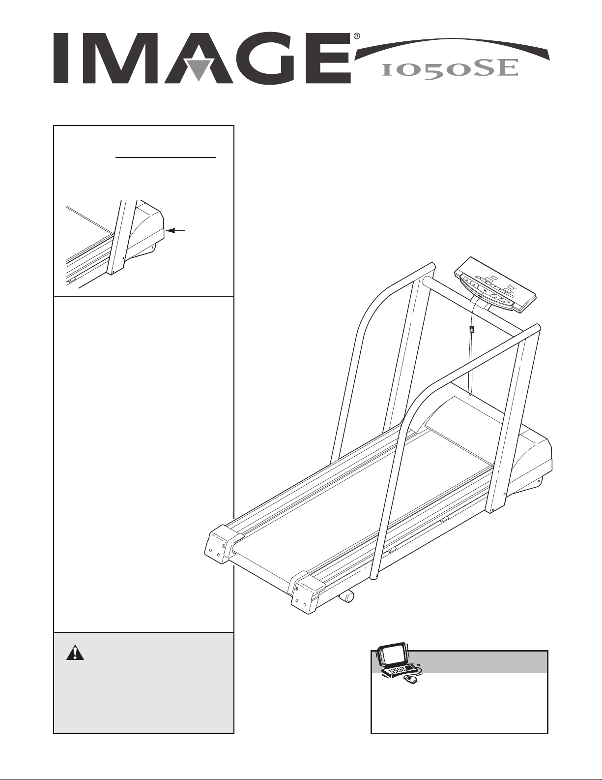
Serial
Number
Decal
Model No. IMTL11901
Serial No.
CAUTION
Read all precautions and instructions in this manual before using
this equipment. Save this manual for future reference.
Write the serial number in the space
above for future reference.
Patent Pending
Visit our website at
www.imagefitness.com
new products, prizes,
fitness tips, and much more!
QUESTIONS?
As a manufacturer, we are committed to providing complete
customer satisfaction. If you
have questions, or if there are
missing parts, we will guarantee
complete satisfaction through direct assistance from our factory.
TO AVOID UNNECESSARY DELAYS, PLEASE CALL DIRECT TO
OUR TOLL-FREE CUSTOMER
HOT LINE. The trained technicians on our Customer Hot Line
will provide immediate assistance, free of charge to you.
CUSTOMER HOT LINE:
1-800-999-3756
Mon.ÐFri., 6 amÐ6 pm MST

IMPORTANT PRECAUTIONS . . . . . . . . . . . . . . . . . . . . . . . . . . . . . . . . . . . . . . . . . . . . . . . . . . . . . . . . . . . . . . . . .2
BEFORE YOU BEGIN . . . . . . . . . . . . . . . . . . . . . . . . . . . . . . . . . . . . . . . . . . . . . . . . . . . . . . . . . . . . . . . . . . . . . . .4
ASSEMBLY . . . . . . . . . . . . . . . . . . . . . . . . . . . . . . . . . . . . . . . . . . . . . . . . . . . . . . . . . . . . . . . . . . . . . . . . . . . . . . .5
HOW TO USE THE HEART RATE MONITOR . . . . . . . . . . . . . . . . . . . . . . . . . . . . . . . . . . . . . . . . . . . . . . . . . . . .6
OPERATION AND ADJUSTMENT . . . . . . . . . . . . . . . . . . . . . . . . . . . . . . . . . . . . . . . . . . . . . . . . . . . . . . . . . . . . .7
TROUBLE-SHOOTING . . . . . . . . . . . . . . . . . . . . . . . . . . . . . . . . . . . . . . . . . . . . . . . . . . . . . . . . . . . . . . . . . . . . .12
CONDITIONING GUIDELINES . . . . . . . . . . . . . . . . . . . . . . . . . . . . . . . . . . . . . . . . . . . . . . . . . . . . . . . . . . . . . . .15
LIMITED WARRANTY . . . . . . . . . . . . . . . . . . . . . . . . . . . . . . . . . . . . . . . . . . . . . . . . . . . . . . . . . . . . . . .Back Cover
Note: An EXPLODED DRAWING, PART LIST and ORDERING REPLACEMENT PARTS information is attached
in the center of this manual.
1. It is the responsibility of the owner to ensure
that all users of this treadmill are adequately
informed of all warnings and precautions.
2. Use the treadmill only as described in this
manual.
3. Place the treadmill on a level surface, with
eight feet of clearance behind it. Do not place
the treadmill on any surface that blocks air
openings. To protect the floor or carpet from
damage, place a mat under the treadmill.
4. Keep the treadmill indoors, away from moisture and dust. Do not put the treadmill in a
garage or covered patio, or near water.
5. Do not operate the treadmill where aerosol
products are used or where oxygen is being
administered.
6. Keep children under the age of 12 and pets
away from the treadmill at all times.
7. The treadmill should not be used by persons
weighing more than 250 pounds.
8. Never allow more than one person on the
treadmill at a time.
9. Wear appropriate exercise clothing when
using the treadmill. Do not wear loose clothing that could become caught in the treadmill.
Athletic support clothes are recommended for
both men and women. Always wear athletic
shoes. Never use the treadmill with bare feet,
wearing only stockings, or in sandals.
10. When connecting the power cord (see page 7),
plug the power cord into a surge suppressor
(not included) and plug the surge suppressor
into a grounded circuit capable of carrying 15
or more amps. No other appliance should be
on the same circuit.
11. Use only a single-outlet surge suppressor that
is UL 1449 listed as a transient voltage surge
suppressor (TVSS). The surge suppressor
must have a UL suppressed voltage rating of
400 volts or less and a minimum surge dissipation of 450 joules. The surge suppressor
must be electrically rated for 120 volts AC and
15 amps. To purchase a surge suppressor, see
your local IMAGE dealer or call 1-800-999-3756
and order part number 146148.
12. Keep the power cord and the surge suppressor away from heated surfaces.
WARNING: To reduce the risk of burns, fire, electric shock, or injury to persons, read the
following important precautions and information before operating the treadmill.
IMPORTANT PRECAUTIONS
TABLE OF CONTENTS
2

13. Never move the walking belt while the power
is turned off. Do not operate the treadmill if
the power cord or plug is damaged, or if the
treadmill is not working properly. (See
BEFORE YOU BEGIN on page 4 if the treadmill is not working properly.)
14. Never start the treadmill while you are standing on the walking belt. Always hold the
handrails while using the treadmill.
15. The treadmill is capable of high speeds.
Adjust the speed in small increments to avoid
sudden jumps in speed.
16. The heart rate monitor is not a medical device. Various factors, including the user's
movement, may affect the accuracy of heart
rate readings. The heart rate monitor is intended only as an exercise aid in determining
heart rate trends in general.
17. Never leave the treadmill unattended while it
is running. Always remove the key, unplug
the power cord, and move the on/off switch to
the off position when the treadmill is not in
use. (See the drawing on page 4 for the location of the on/off switch.)
18. Inspect and tighten all parts of the treadmill
every three months.
19. Never drop or insert any object into any opening.
20. DANGER: Always unplug the power
cord immediately after use, before cleaning
the treadmill, and before performing the maintenance and adjustment procedures described in this manual. Never remove the
motor hood unless instructed to do so by an
authorized service representative. Servicing
other than the procedures in this manual
should be performed by an authorized service
representative only.
21. This treadmill is intended for in-home use
only. Do not use this treadmill in any commercial, rental, or institutional setting.
WARNING: Before beginning this or any exercise program, consult your physician. This
is especially important for persons over the age of 35 or persons with pre-existing health problems.
Read all instructions before using. ICON assumes no responsibility for personal injury or property
damage sustained by or through the use of this product.
SAVE THESE INSTRUCTIONS
3
Thank you for selecting the new IMAGE¨1050SE
treadmill. The IMAGE 1050SE treadmill combines advanced technology with innovative design to let you
enjoy an effective form of cardiovascular exercise in
the convenience and privacy of your home.
For your benefit, read this manual carefully before
using the treadmill. If you have additional questions,
please call our Customer Service Department toll-free
at 1-800-999-3756, Monday through Friday, 6 a.m.
until 6 p.m. Mountain Time (excluding holidays). To
help us assist you, please note the product model
number and serial number before calling. The model
number of the treadmill is IMTL11901. The serial number can be found on a decal attached to the treadmill
(see the front cover of this manual for the location).
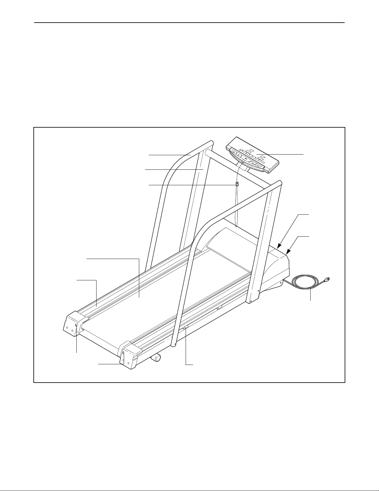
Before reading further, please familiarize yourself with
the parts that are labeled in the drawing below.
Handrail
Key/Clip
Circuit
Breaker
Walking Belt
Foot Rail
Power Cord
Rear Roller
Adjustment Bolts
Console
Upright
On/Off
Switch
BEFORE YOU BEGIN
Cushioned Walking Platform
4
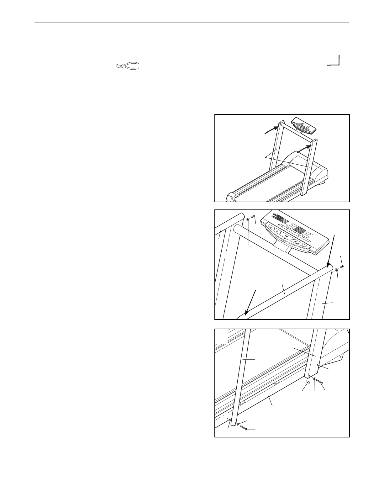
ASSEMBLY
Assembly requires two people. Set the treadmill in a cleared area and remove all packing materials. Do not
dispose of the packing materials until assembly is completed. Assembly requires the included allen wrench
and your own wire cutters (not included).
Note: The underside of the treadmill walking belt is coated with high-performance lubricant. During shipping, a
small amount of lubricant may be transferred to the top of the walking belt or the shipping carton. This is a normal
condition and does not affect treadmill performance. If there is lubricant on top of the walking belt, simply wipe off
the lubricant with a soft cloth and a mild, non-abrasive cleaner.
2. Cut any plastic ties from the Right and Left Handrails (93,
7). Set the Right Handrail (the longer Handrail) on the
right Upright (80). Have another person lift the Handrail at
the indicated location. While pressing down on the
Handrail at the indicated location, firmly tighten a Short
Handrail Bolt (59) with a Washer (60) into the Upright and
the Right Handrail.
Attach the Left Handrail (7) as described above.
1. With the help of a second person, carefully raise the
Uprights (80) until the treadmill is in the position shown.
80
1
93
80
7
59
59
60
60
2
3. Insert a Long Handrail Bolt (37) with a Washer (60) and a
Plastic Washer (53) into the lower end of the Right
Handrail (93) as shown. Finger tighten the Long Handrail
Bolt into the Frame (87).
Next, hold an Upright Spacer (11) inside the lower end of
the right Upright (80). Insert a Long Handrail Bolt (37) with
a Washer (60) through the Upright and the Upright Spacer,
and finger tighten the Upright Bolt into the Frame (87).
Repeat this step on the left side of the treadmill (not shown).
Tighten the three Long Handrail Bolts (37) on each side of
the treadmill.
60
53
87
11
93
37
37
60
37
80
4. Make sure that all parts are tightened before you use the treadmill. Keep the included allen wrench in a
secure place. The allen wrench is used to adjust the walking belt (see pages 12 and 13). To protect the floor
or carpet from damage, place a mat under the treadmill.
5
3
Lift Here
Press
Down
Here
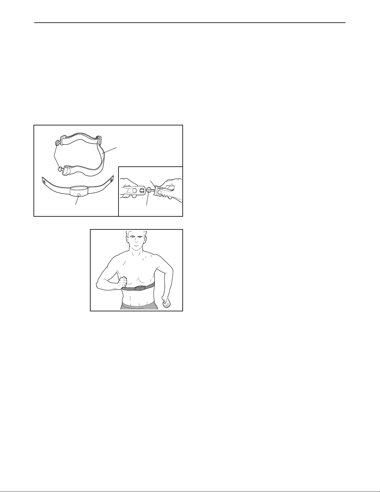
HOW TO PUT ON THE HEART RATE MONITOR
The heart rate monitor consists of two components:
the chest strap and the sensor unit (see the drawing
below). Insert the tab on one end of the chest strap
through the hole in one end of the sensor unit. Press
the end of the sensor unit under the buckle on the chest
strap. The tab should be almost flush with the front of
the sensor unit.
Next, wrap the
heart rate monitor around your
chest and
attach the other
end of the chest
strap to the sensor unit. Adjust
the length of the
chest strap, if
necessary. The
heart rate monitor should be under your clothing, tight against your
skin, and as high under the pectoral muscles or
breasts as is comfortable. Make sure that the logo on
the sensor unit is facing forward and is right-side-up.
Pull the sensor unit away from your body a few inches
and locate the two electrode areas on the inner side.
The electrode areas are the areas covered by shallow
ridges. Using saline solution such as saliva or contact
lens solution, wet both electrode areas. Return the
sensor unit to a position against your chest.
HEART RATE MONITOR CARE AND MAINTENANCE
¥ Thoroughly dry the heart rate monitor after each
use. The heart rate monitor is activated when the
electrode areas are wetted and the heart rate
monitor is put on; the heart rate monitor shuts off
when it is removed and the electrode areas are
dried. If the heart rate monitor is not dried after each
use, it may remain activated longer than necessary,
draining the battery prematurely.
¥ Store the heart rate monitor in a warm, dry place.
Do not store the heart rate monitor in a plastic bag
or other container that may trap moisture.
¥ Do not expose the heart rate monitor to direct
sunlight for extended periods of time; do not expose
it to temperatures above 122¡ Fahrenheit (50¡
Celsius) or below 14¡ Fahrenheit (-10¡ Celsius).
¥ Do not excessively bend or stretch the sensor unit
when using or storing the heart rate monitor.
¥ Clean the sensor unit using a damp clothÑnever
use alcohol, abrasives, or chemicals. The chest
strap may be hand washed and air dried.
HEART RATE MONITOR TROUBLE-SHOOTING
The instructions on the following pages explain
how the heart rate monitor is used with the console.
If the heart rate monitor does not function properly,
try the steps below.
¥ Make sure that the heart rate monitor is under your
clothing, tight against your skin, and as high under
the pectoral muscles or breasts as is comfortable.
The logo on the sensor unit must be facing forward
and be right-side-up. Note: If the heart rate monitor
does not function when positioned as described, try
moving it slightly lower or higher on your chest.
¥ Use saline solution such as saliva or contact lens
solution to wet the two electrode areas on the
sensor unit. If heart rate readings do not appear until
you begin perspiring, re-wet the electrode areas.
¥ As you walk or run on the treadmill, position your-
self near the center of the walking belt. For the
console to display heart rate readings, the user
must be within armÕs length of the console.
¥ The heart rate monitor is designed to work with
people who have normal heart rhythms. Heart rate
reading problems may be caused by medical
conditions such as premature ventricular contractions (pvcs), tachycardia bursts, and arrhythmia.
¥ The operation of the heart rate monitor can be
affected by magnetic interference caused by high
power lines or other sources. If it is suspected that
this is a problem, try relocating the treadmill.
¥ The CR2032 battery may need to be replaced (see
page 14).
HOW TO USE THE HEART RATE MONITOR
Chest Strap
Tabs
Sensor Unit
Tab
Buckle
6

OPERATION AND ADJUSTMENT
THE PERFORMANT LUBETMWALKING BELT
Your treadmill features a walking belt coated with
PERFORMANT LUBETM, a high-performance lubricant.
IMPORTANT: Never apply silicone spray or other
substances to the walking belt or the walking platform. Such substances will deteriorate the walking
belt and cause excessive wear.
HOW TO PLUG IN THE POWER CORD
Your treadmill, like any other type of sophisticated
electronic equipment, can be seriously damaged by
sudden voltage changes in your homeÕs power.
Voltage surges, spikes, and noise interference can
result from weather conditions or from other appliances
being turned on or off. To decrease the possibility of
your treadmill being damaged, always use a surge
suppressor with your treadmill (see drawing 1 at
the right).
To purchase a surge suppressor, see your local
IMAGE dealer or call 1-800-999-3756 and order part
number 146148. Use only a single-outlet surge sup-
pressor that is UL 1449 listed as a transient voltage
surge suppressor (TVSS). The surge suppressor must
have a UL suppressed voltage rating of 400 volts or
less and a minimum surge dissipation of 450 joules.
The surge suppressor must be electrically rated for
120 volts AC and 15 amps.
This product must be grounded. If it should malfunction or break down, grounding provides a path of least
resistance for electric current to reduce the risk of electric shock. This product is equipped with a cord having
an equipment-grounding conductor and a grounding
plug. Plug the power cord into a surge suppressor,
and plug the surge suppressor into an appropriate
outlet that is properly installed and grounded in
accordance with all local codes and ordinances.
Important: The treadmill is not compatible with
GFCI-equipped outlets.
This product is for use on a nominal 120-volt circuit,
and has a grounding plug that looks like the plug illustrated in drawing 1 below. A temporary adapter that
looks like the adapter illustrated in drawing 2 may be
used to connect the surge suppressor to a 2-pole
receptacle as shown in drawing 2 if a properly
grounded outlet is not available.
The temporary adapter should be used only until a
properly grounded outlet (drawing 1) can be installed
by a qualified electrician.
The green-colored rigid ear, lug, or the like extending
from the adapter must be connected to a permanent
ground such as a properly grounded outlet box cover.
Whenever the adapter is used it must be held in place
by a metal screw. Some 2-pole receptacle outlet box
covers are not grounded. Contact a qualified electrician to determine if the outlet box cover is
grounded before using an adapter.
DANGER: Improper connection
of the equipment-grounding conductor can
result in an increased risk of electric shock.
Check with a qualified electrician or serviceman if you are in doubt as to whether the
product is properly grounded. Do not modify
the plug provided with the productÑif it will
not fit the outlet, have a proper outlet
installed by a qualified electrician.
1
2
Grounded Outlet Box
Grounded Outlet Box
Grounding Plug
Surge Suppressor
Surge Suppressor
Grounding Pin
Adapter
Lug
Metal Screw
Grounded Outlet
Grounding Pin
7

Clip
Key
DisplaysDisplays
LED Track/
Program Display
FEATURES OF THE CONSOLE
The treadmill console offers an impressive array of
features to help you get the most from your workouts.
When the manual mode is selected, the speed and incline of the treadmill can be changed with a touch of a
button. As you exercise, the LED track and the four displays will provide continuous exercise feedback. You
can even measure your heart rate using the heart rate
monitor. Twelve preset programs are also offered. Each
program automatically controls the speed and incline of
the treadmill to give you an effective low-, medium-, or
high-intensity workout.
GETTING STARTED
Attach the clip to the waistband of your clothes.
Stand on the foot rails of the treadmill. Find the
clip attached to the key (see the drawing above),
and slide the clip onto the waistband of your
clothes. Next, insert the key fully into the console.
Test the clip by carefully taking a few steps
backward until the key is pulled from the console. If the key is not pulled from the console,
adjust the position of the clip as needed. Then,
remove the key from the console.
Plug in the power cord.
See page 7.
Move the on/off switch to the on position.
Locate the on/off
switch on the treadmill
near the power cord.
Move the switch to the
on position.
Insert the key fully into the console.
When the key is inserted, the four displays and
various indicators on the console will light.
Note: The console can display speed and distance in
either miles or kilometers (see SPEED/PACE display
on page 9). For simplicity, all instructions in this manual
refer to miles.
4
3
2
1
CAUTION: Before operating the
console, read the following precautions.
¥ Do not stand on the walking belt when turn-
ing on the power.
¥ Always wear the clip (see the drawing above)
while operating the treadmill. If the key is
pulled from the console, the walking belt will
automatically stop.
¥ Adjust the speed in small increments to
avoid sudden jumps in speed.
¥ To reduce the possibility of electric shock,
keep the console dry. Avoid spilling liquids
on the console, and place only a sealed
water bottle in the water bottle holder.
On
Position
Manual/Program Indicators
Note: If there is a sheet of clear plastic
on the face of the console, remove it.
8

HOW TO USE THE MANUAL MODE
Insert the key fully into the console.
See GETTING STARTED on page 8.
Select the manual mode.
When the key is
inserted, the manual
mode will automatically be selected, as
shown by the MANUAL indicator. If you
have selected a preset program, press
the PROGRAM button repeatedly until the MANUAL
indicator lights.
Put on the heart rate monitor if desired.
For the CALORIES/PULSE display to show your
heart rate, the heart rate monitor must be worn.
See page 6.
Press the START button or the SPEED
▲▲
but-
ton to start the walking belt.
A moment after the button is pressed, the walking
belt will begin to move at 1 mph. Hold the
handrails and begin walking.
As you exercise, change the speed of the walking
belt as desired by pressing the SPEED buttons.
Each time a button is pressed, the speed will
change by 0.1 mph. The buttons can be held
down to change the speed setting quickly. Note: It
may take a few seconds for the walking belt to
reach the selected speed setting.
To stop the walking belt, press the STOP button.
The TIME/INCLINE display will begin to flash. To
restart the walking belt, press the START button or
the SPEED
▲▲
button.
Adjust the incline of the treadmill as desired.
To change the incline of the treadmill, press the
INCLINE buttons. Each time a button is pressed,
the incline will change by 0.5%. The buttons can be
held down to change the incline quickly. Note: It
may take a few seconds for the treadmill to reach
the selected incline setting.
Follow your progress with the LED track and
the four displays.
The LED TrackÑWhen
the manual mode is selected, the program display will show a track
that represents a distance of 1/4 mile. As you
exercise, the indicators
around the track will light one at a time until you
have completed 1/4 mile. A new lap will then begin.
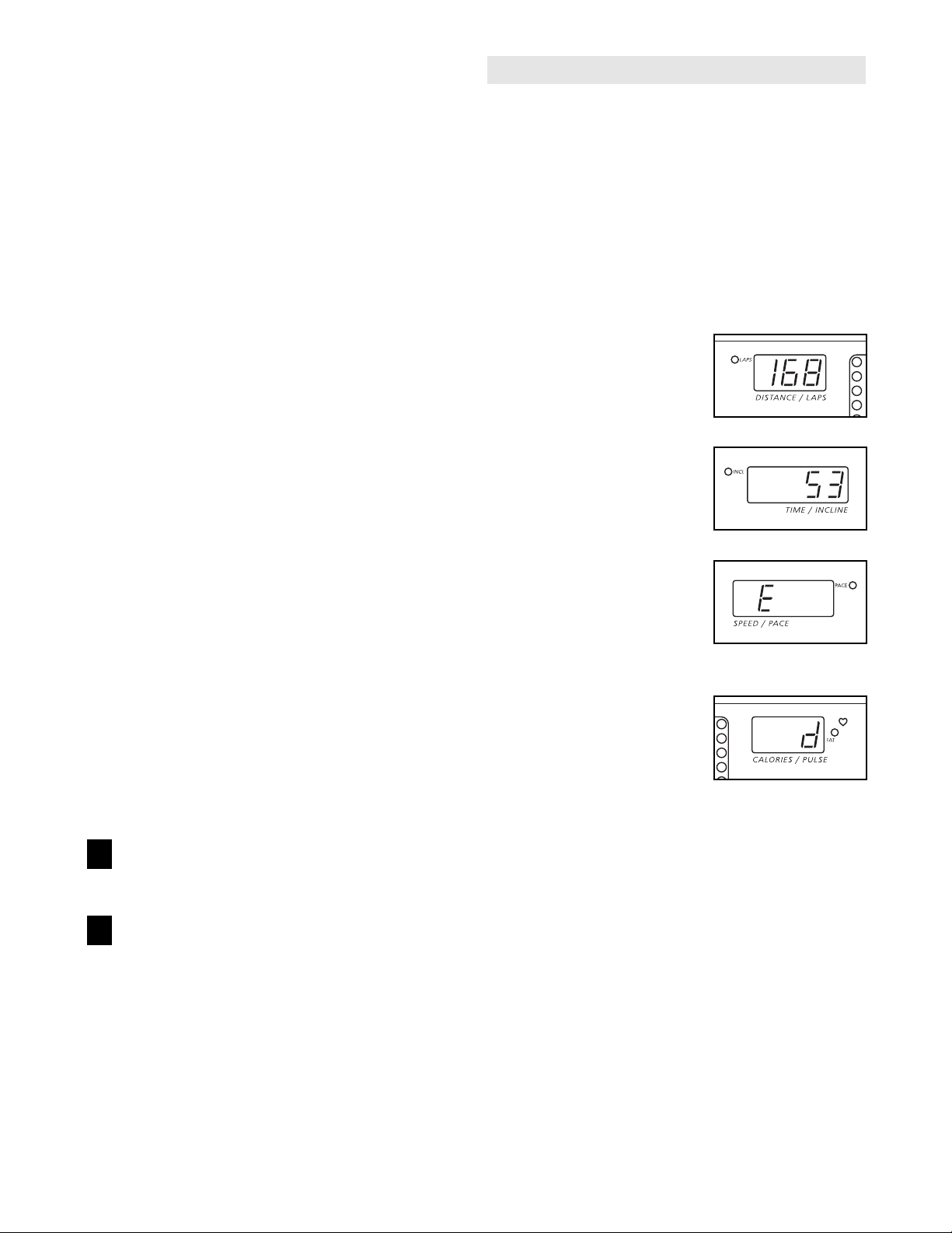
DISTANCE/LAPS
displayÑThis display
shows the distance that
the walking belt has
moved and the number
of 1/4-mile laps you have
completed. The display will change from one number to the other every seven seconds; the indicator
will light when the number of laps is shown.
TIME/INCLINE
displayÑThis display
shows the elapsed time
and the incline level of
the treadmill. The
display will change
from one number to the other every seven seconds;
the indicator will light when the incline is shown.
Note: When a preset program is selected, the display will show the time remaining in the program.
SPEED/PACE
displayÑThis display
shows the speed of the
walking belt and your
current pace (pace is
measured in minutes per
mile). Every seven seconds, the display will change
from one number to the other; the indicator will light
when your pace is shown.
Note: The console can
display distance, speed,
and pace in either miles
or kilometers. To see
which unit of measurement is selected, hold
down the STOP button, insert the key into the console, and continue pressing the STOP button for a
moment. An ÒEÓ for English miles, or an ÒMÓ for
metric kilometers, will appear in the SPEED/PACE
display. To change the unit of measurement, press
the SPEED
▲▲
button. Then, remove and reinsert
the key.
6
5
4
3
2
1
Indicator
9

CALORIES/PULSE
displayÑThis display
shows the approximate
numbers of calories and
fat calories you have
burned (see FAT BURNING on page 15). Every seven seconds, the display will change from one number to the other; the
indicator will light when the number of fat calories
is shown. This display will also show your heart
rate when the heart rate monitor is worn; the heartshaped indicator will light when your heart rate is
shown.
When you are finished exercising, press the
STOP button and remove the key.
Step onto the foot rails, press the STOP button,
and remove the key from the console. Keep the
key in a secure place. Note: If the displays and
various indicators on the console remain lit
after the key is removed, the console is in the
ÒdemoÓ mode. Refer to page 11 and turn off the
demo mode.
In addition, move the on/off switch to the off position and unplug the power cord.
HOW TO USE PRESET PROGRAMS
Insert the key fully into the console.
See GETTING STARTED on page 8.
Press the PROGRAM button to select the desired preset program.
When the key is inserted, the manual
mode will be selected. To select one
of the preset programs, press the
PROGRAM button
repeatedly until one
of the twelve program indicators lights.
The console offers four low-intensity programs (L1
to L4), four medium-intensity programs (M1 to
M4), and four high-intensity programs (H1 to H4).
The profiles on the sides of the console show how
the speed and incline of the treadmill will change
during the programs. The numbers beside the
profiles show the maximum speed and incline settings for the programs. For example, the upper left
profile shows that the treadmill will reach a maximum speed of 3.5 mph and a maximum incline of
3% during the first program (L1).
The program display will
show a simplified profile
of the program you have
selected. The TIME/INCLINE display will show
how long the program
will last.
Put on the heart rate monitor if desired.
For the CALORIES/PULSE display to show your
heart rate, the heart rate monitor must be worn.
See page 6.
Press the START button or the SPEED
▲▲
button
to start the program.
A moment after the button is pressed, the treadmill will automatically adjust to the first speed and
incline settings for the program. Hold the handrails
and begin walking.
Each program is divided
into several time segments of different
lengths. One speed setting and one incline setting are programmed for
each segment. The
speed setting for the
first segment will be shown in the flashing Current
Segment column of the program display. (The incline settings are not shown in the program display.) The speed settings for the next several segments will be shown in the columns to the right.
When only three seconds remain in the first segment of the program, both the Current Segment
column and the column to the right will flash, a series of tones will sound, and all speed settings will
move one column to the left. The speed setting for
the second segment will then be shown in the
flashing Current Segment column and the treadmill will automatically adjust to the speed and incline settings for the second segment.
4
3
2
1
7
Indicator
Current Segment
10
The program will continue in this way until the
speed setting for the last segment is shown in the
Current Segment column and no time remains in
the TIME/INCLINE display. The walking belt will
then slow to a stop.
Note: Each time a segment ends and the speed
settings move one column to the left, if all of the
indicators in the Current Segment column are lit,
the speed settings will move downward so that only
the highest indicators in the columns will appear in
the program display. When the speed settings
move to the left again and not all of the indicators
in the Current Segment column are lit, the speed
settings will move back up.
If the speed or incline setting for the current
segment is too high or too low, you can manually
override the setting by pressing the SPEED or
INCLINE buttons. Every few times one of the
SPEED buttons is pressed, an additional indicator
will light or darken in the Current Segment column.
If any of the columns to the right of the Current
Segment column have the same number of lit indicators as the Current Segment column, an additional indicator may light or darken in those
columns as well. Note: If you manually adjust the
speed setting so that all of the indicators in the
Current Segment column are lit, the speed settings
in the program display will not move downward as
described above. When the current segment of
the program ends, the treadmill will automatically adjust to the speed and incline settings
for the next segment.
To stop the program temporarily, press the STOP
button. The TIME/INCLINE display will begin to
flash. To restart the program, press the START
button or the SPEED▲▲button. To end the program, press the STOP button, remove the key,
and then reinsert the key.
Follow your progress with the displays.
See step 6 on page 9.
When the program is completed, remove the
key from the console.
See step 7 on page 10.
THE INFORMATION MODE/DEMO MODE
The console features an information mode that keeps
track of the total number of hours that the treadmill has
been operated and the total number of miles that the
walking belt has moved. The information mode also
allows you to switch the console from miles to kilometers and to turn the demo mode off and on.
To select the information mode, hold down the STOP
button, insert the key into the console, and continue
pressing the STOP button for a moment. The following
information will be shown:
The DISTANCE/LAPS
display will show the total
number of miles that the
walking belt has moved.
The TIME/INCLINE display
will show the total number of
hours the treadmill has been
used.
An ÒEÓ for English miles, or
an ÒMÓ for metric kilometers,
will appear in the SPEED/
PACE display. Press the
SPEED
▲▲
button to change
the unit of measurement.
IMPORTANT: The CALORIES/PULSE display should
be blank. If a ÒdÓ appears in
the display, the console is in
the ÒdemoÓ mode. This mode
is intended to be used only
when a treadmill is displayed in a store. When the console is in the demo mode, the power cord can be
plugged in, the key can be removed from the console,
and the displays and indicators on the console will automatically light in a preset sequence, although the
buttons on the console will not operate. If a ÒdÓ appears
in the CALORIES/PULSE display when the information mode is selected, press the SPEED▼▼button
so the CALORIES/PULSE display is blank.
To exit the information mode, remove the key from the
console.
6
5
11

TROUBLE-SHOOTING
Most treadmill problems can be solved by following the steps below. Find the symptom that applies, and
follow the steps listed. If further assistance is needed, please call our Customer Service Department tollfree at 1-800-999-3756, Monday through Friday, 6 a.m. until 6 p.m. Mountain Time (excluding holidays).
PROBLEM: The power does not turn on
SOLUTION: a. Make sure that the power cord is plugged into a surge suppressor, and that the surge suppressor
is plugged into a properly grounded outlet (see page 7). Use only a single-outlet surge suppressor that is UL 1449 listed as a transient voltage surge suppressor (TVSS). The surge suppressor
must have a UL suppressed voltage rating of 400 volts or less and a minimum surge dissipation
of 450 joules. The surge suppressor must be electrically rated for 120 volts AC and 15 amps.
Important: The treadmill is not compatible with GFCI-equipped outlets.
b. After the power cord has been plugged in, make sure that the key is fully inserted into the console.
c. Check the circuit breaker located on the treadmill
near the power cord. If the switch protrudes as
shown, the circuit breaker has tripped. To reset the
circuit breaker, wait for five minutes and then press
the switch back in.
d. Check the on/off switch located on the treadmill
near the power cord. The switch must be in the on
position.
PROBLEM: The power turns off during use
SOLUTION: a. Check the circuit breaker located on the treadmill near the power cord. If the circuit breaker has
tripped, wait for five minutes and then press the switch back in.
b. Make sure that the power cord is plugged in.
c. Remove the key from the console. Reinsert the key fully into the console.
d. Make sure that the on/off switch is in the on position.
e. If the treadmill still will not run, please call our Customer Service Department, toll-free.
PROBLEM: The walking belt slows when walked on
SOLUTION: a. Use only an appropriate surge suppressor (see a. near the top of this page).
b. If the walking belt is overtightened, treadmill perfor-
mance may decrease and the walking belt may become damaged. Remove the key and UNPLUG THE
POWER CORD. Using the allen wrench, turn both
rear roller adjustment bolts counterclockwise 1/4 of a
turn. When the walking belt is properly tightened, you
should be able to lift each side of the walking belt 3 to
4 inches off the walking platform. Be careful to keep
the walking belt centered. Plug in the power cord, insert the key, and run the treadmill for a few minutes.
Repeat until the walking belt is properly tightened.
c. If the walking belt still slows when walked on, please call our Customer Service Department, toll-
free.
Tripped
c
Reset
On
Position
Rear
Roller
Bolts
3ÓÐ4Ó
b
d
12
Tripped
Reset

PROBLEM: The walking belt is off-center
SOLUTION: a. If the walking belt has shifted to the left, first re-
move the key and UNPLUG THE POWER CORD.
Using the allen wrench, turn the left rear roller adjustment bolt clockwise, and the right bolt counterclockwise, 1/4 of a turn each. Be careful not to overtighten
the walking belt. Plug in the power cord, insert the key
and run the treadmill for a few minutes. Repeat until
the walking belt is centered.
b. If the walking belt has shifted to the right, first re-
move the key and UNPLUG THE POWER CORD.
Using the allen wrench, turn the left rear roller adjustment bolt counterclockwise, and the right bolt clockwise, 1/4 of a turn each. Be careful not to overtighten
the walking belt. Plug in the power cord, insert the key
and run the treadmill for a few minutes. Repeat until
the walking belt is centered.
c. If the walking belt slips when walked on, first re-
move the key and UNPLUG THE POWER CORD.
Using the allen wrench, turn both rear roller adjustment bolts clockwise 1/4 of a turn. When the walking
belt is correctly tightened, you should be able to lift
each side of the walking belt 3 to 4 inches off the walking platform. Be careful to keep the walking belt centered. Plug in the power cord, insert the key and carefully walk on the treadmill for a few minutes. Repeat
until the walking belt is properly tightened.
PROBLEM: The SPEED/PACE display on the console does not function properly
SOLUTION: a. Remove the key from the console and unplug the
power cord. Remove the screws from the hood and
carefully remove the hood. Locate the Reed Switch
(17) and the Magnet (69) on the left side of the Pulley
(72). Turn the Pulley until the Magnet is aligned with
the Reed Switch. Make sure that the gap between
the Magnet and the Reed Switch is about 1/8Ó. If
necessary, loosen the Reed Switch Screw (19) and
move the Reed Switch slightly. Retighten the Screw.
Re-attach the hood and run the treadmill for a few
minutes to check for a correct speed reading.
PROBLEM: The incline of the treadmill does not change correctly
SOLUTION: a. With the key in the console, press one of the INCLINE buttons. While the incline is changing,
remove the key. After a few seconds, re-insert the key. The treadmill will automatically rise to the
maximum incline level and then return to the minimum level. This will recalibrate the incline system.
b
c
a
69
17
19
Top
View
1/8Ó
72
a
13

PROBLEM: The heart rate monitor does not function properly
SOLUTION: a. If the heart rate monitor does not function properly, see HEART RATE MONITOR TROUBLE-
SHOOTING on page 6.
b. If the heart rate monitor still does not function properly, the battery
should be changed. To replace the battery, locate the battery cover
on the back of the sensor unit. Insert a coin into the slot in the cover
and turn the cover counterclockwise to the ÒopenÓ position. Remove
the cover.
Remove the old battery from the sensor unit. Insert a new CR 2032
battery, making sure that the writing is on top. In addition, make sure
that the rubber gasket is in place in the sensor unit. Replace the battery cover and turn it to the closed position.
Battery
Rubber
Gasket
Battery Cover
Battery
Cover
14

CONDITIONING GUIDELINES
The following guidelines will help you to plan your exercise program. For more detailed information about
exercise, obtain a book or consult your physician.
EXERCISE INTENSITY
Whether your goal is to burn fat or strengthen your cardiovascular system, the key to achieving the desired
results is to exercise with the proper intensity. The
proper intensity level can be found by using your heart
rate as a guide. For effective exercise, your heart rate
should be maintained at a level between 65% and 85%
of your maximum heart rate as you exercise. This is
known as your training zone. You can find your training
zone in the table below. Training zones are listed according to age and physical condition.
Fat Burning
To burn fat, you must exercise at a low intensity level
for a sustained period of time. During the first few
minutes of exercise, your body uses easily accessible
carbohydrate calories for energy. Only after the first few
minutes of exercise does your body begin to use stored
fat calories for energy. If your goal is to burn fat, adjust
the intensity of your exercise until your heart rate is
near the low end of your training zone as you exercise.
Aerobic Exercise
If your goal is to strengthen your cardiovascular system, your exercise must be Òaerobic.Ó Aerobic exercise
is activity that requires large amounts of oxygen for
prolonged periods of time. This increases the demand
on the heart to pump blood to the muscles, and on the
lungs to oxygenate the blood. For aerobic exercise,
adjust the intensity of your exercise until your heart
rate is near the middle of your training zone.
WORKOUT GUIDELINES
Each workout should include the following three important parts:
A Warm-upÑWarming up prepares the body for exercise by increasing circulation, delivering more oxygen
to the muscles, and raising the body temperature.
Begin each workout with 5 to 10 minutes of stretching
and light exercise to warm up.
Training Zone ExerciseÑAfter warming up, increase
the intensity of your exercise until your heart rate is in
your training zone for 20 to 60 minutes. (During the
first few weeks of your exercise program, do not keep
your heart rate in your training zone for longer than 20
minutes.) Breathe regularly and deeply as you exerciseÑnever hold your breath.
A cool-downÑFinish each workout with 5 to 10 minutes of stretching to cool down. This will increase the
flexibility of your muscles and will help to prevent postexercise problems.
EXERCISE FREQUENCY
To maintain or improve your condition, complete three
workouts each week, with at least one day of rest between workouts. After a few months, you may complete up to five workouts each week if desired.
The key to success is to make exercise a regular and
enjoyable part of your everyday life.
WARNING: Before beginning
any exercise program, consult your physician. This is especially important for individuals over the age of 35 or individuals with preexisting health problems.
The heart rate monitor is not a medical de-
vice. Various factors may affect the accuracy
of heart rate readings. The heart rate monitor
is intended only as an exercise aid in determining heart rate trends in general.
20 138-167 133-162
25 136-166 132-160
30 135-164 130-158
35 134-162 129-156
40 132-161 127-155
45 131-159 125-153
50 129-156 124-150
55 127-155 122-149
60 126-153 121-147
65 125-151 119-145
70 123-150 118-144
75 122-147 117-142
80 120-146 115-140
Age
Unconditioned Conditioned
Training Zone (Beats/Min.)
15

Note: To identify the parts listed below, refer to the EXPLODED DRAWING attached in the center of this manual.
PART LISTÑModel No. IMTL11901 R1000A
Key No. Qty. Description Key No. Qty. Description
1 4 Console Base Screw
2 12 Belly Pan Screw
3* 1 Idler Arm Assembly
4 4 Nylon Washer
5 2 Incline Bolt
6 1 Idler Pivot Bolt
7 1 Left Handrail
8 2 Handrail Cap
9 8 Cage Nut
10 2 Wheel Bolt
11 2 Upright Spacer
12 5 Nut
13 1 Incline Motor Bolt
14 4 Endcap Bolt
15 2 Roller Adjustment Bolt
16 2 Rear Platform Screw
17 1 Reed Switch
18 1 Reed Switch Clip
19 1 Reed Switch Screw
20 5 Hood Anchor Screw
21 5 Hood Anchor
22 3 Tie Holder
23 2 Motor Bushing
24 1 Idler Arm Bushing
25 1 Motor Isolator
26 1 Idler Arm
27 19 Screw
28 1 Idler Spring
29 5 Hood Screw
30 8 Platform Screw
31 4 8Ó Wire Tie
32 1 Rear Endcap (Left)
33 1 Idler Arm Washer
34 1 Allen Wrench
35 1 Flywheel Guard
36 1 Power Supply w/Clips
37 6 Handrail Bolt (Long)
38 1 Switch Bracket
39 1 Circuit Breaker
40 1 On/Off Switch
41 1 Controller
42 1 Power Cord
43 1 Grommet
44 1 Electronics Bracket
45 1 Idler Arm Nut
46 1 Optic Sensor Wire
47 3 Releasable Wire Tie
48 1 Front Roller Ground Wire
49 1 Motor-Controller Wire
50 2 Frame Endcaps
51 3 Adjustment Washer
52 1 Idler Pulley
53 4 Plastic Washer
54 2 Wheel Nut
55 2 Foot Endcap
56 2 Belt Guide
57 2 Incline Wheel
58 1 Motor Belt
59 2 Handrail Bolt (Short)
60 15 Washer
61* 1 Motor/Pulley/Flywheel/Fan
62 1 Wire Harness
63 2 Wire Harness Grommet
64 1 Key/Clip
65 1 Pulley Bushing
66 1 Chest Pulse Strap
67 1 Idler Pulley Bolt
68 1 Console
69 1 Magnet
70 6 Isolator
71 1 Incline Motor
72 1 Front Roller
73 1 Rear Roller
74 1 Foot Rail (Left)
75 1 Incline Leg
76 1 Chest Pulse Sensor
77 1 Rear Roller Ground Wire
78 4 Plastic Standoff
79 1 Front Roller Adjustment Bolt
80 1 Upright
81 2 Motor Bolt
82 1 Incline Motor Bolt (Top)
83 1 Walking Belt
84 1 Walking Platform
85 1 Hood
86 1 Belly Pan
87 1 Frame
88 1 Foot Rail (Right)
89 1 Rear Endcap (Right)
90 1 Staple Cover (Left)
91 1 Staple Cover (Right)
92 1 40Ó Pulse Wire
93 1 Right Handrail
# 1 8Ó White Wire, 2 Female
# 1 4Ó White Wire, Male/Female
# 1 4Ó Black Wire, 2 Female
# 1 8Ó Blue Wire, 2 Female
# 1 4Ó Blue Wire, 2 Female
# 1 8Ó Green Wire, F/Ring
# 1 UserÕs Manual
* Includes all parts shown in the box
# These parts are not illustrated

REMOVE THIS EXPLODED DRAWING
AND PART LIST FROM THE MANUAL
Save this EXPLODED DRAWING and PART LIST and the USERÕS
MANUAL for future reference.
ORDERING REPLACEMENT PARTS
To order replacement parts, call our Customer Service Department toll-free at 1-800-999-3756, Monday through
Friday, 6 a.m. until 6 p.m. Mountain Time (excluding holidays). When ordering parts, please be prepared to give
the following information:
When requesting help or service, or ordering parts, please be prepared to provide the following information:
¥ The MODEL NUMBER of the product (IMTL11901)
¥ The NAME of the product (IMAGE¨1050SE treadmill)
¥ The SERIAL NUMBER of the product (see the front cover of this manual)
¥ The KEY NUMBER AND DESCRIPTION OF THE PART (see the PART LIST and the EXPLODED DRAWING in
the center of this manual)
If possible, place the treadmill near your telephone for easy reference when calling.

37
29
29
37
29
31
34
50
50
55
62
62
63
64
32
85
87
74
11
53
47
27
22
27
11
53
90
9
9
20
21
20
21
27
37
37
59
59
60
8
8
55
60
60
60
60
21
53
53
60
27
77
49
1
1
1
80
92
63
7
93
66
76
68
72
84
83
88
91
35
3*
26
37
28
65
46
52
45
67
24
6
33
25
14
15
51
14
36
78
27
27
39
40
42
43
27
38
20
21
79
51
20
21
41
27
16
30
27
70
27
56
48
20
30
69
17
18
19
10
5
5
10
54
12
13
57
57
75
12
54
9
89
14
15
51
58
61*
30
27
70
27
70
9
27
82
12
81
23
2
2
86
70
27
56
27
71
44
73
70
70
4
4
9
9
9
9
60
60
EXPLODED DRAWINGÑModel No. IMTL11901 R1000A

Part No. 171038 R1000A Printed in USA © 2000 ICON Health & Fitness, Inc.
LIMITED WARRANTY
WHAT IS COVEREDÑThe entire IMAGE¨1050SE (ÒProductÓ) is warranted to be free of all defects in material and workmanship.
WHO IS COVEREDÑThe original purchaser or any person receiving the Product as a gift from the original purchaser.
HOW LONG IS IT COVEREDÑICON Health & Fitness, Inc. (ÒICONÓ), warrants the motor for three years after the date
of purchase. The belt and deck are covered for two years after the date of purchase. All mechanical components are
covered for two years after the date of purchase. All electrical components are covered for two years after the date of
purchase. Labor is covered for one year.
WHAT WE DO TO CORRECT COVERED DEFECTSÑWe will ship to you, without charge, any replacement part or component, providing the repairs are authorized by ICON first and are performed by an ICON trained and authorized service
provider, or, at our option, we will replace the Product.
WHAT IS NOT COVEREDÑAny failures or damage caused by unauthorized service, misuse, accident, negligence, improper assembly or installation, alterations, modifications without our written authorization or by failure on your part to use,
operate, and maintain as set out in your UserÕs Manual (ÒManualÓ).
WHAT YOU MUST DOÑAlways retain proof of purchase, such as your bill of sale; store, operate, and maintain the
Product as specified in the Manual; notify our Customer Service Department of any defect within 10 days after discovery of
the defect; as instructed, return any defected part for replacement or, if necessary, the entire product, for repair.
USERÕS MANUALÑIt is VERY IMPORTANT THAT YOU READ THE MANUAL before operating the Product. Remember
to do the periodic maintenance requirements specified in the Manual to assure proper operation and your continued satisfaction.
HOW TO GET PARTS AND SERVICEÑSimply call our Customer Service Department at 1-800-999-3756 and tell them
your name and address and the serial number of your Product. They will tell you how to get a part replaced, or if necessary, arrange for service where your Product is located or advise you how to ship the Product for service. Before shipping,
always obtain a Return Authorization Number (RA No.) from our Customer Service Department; securely pack your
Product (save the original shipping carton if possible); put the RA No. on the outside of the carton and insure the product.
Include a letter explaining the product or problem and a copy of your proof of purchase if you believe the service is covered
by warranty.
ICON is not responsible or liable for indirect, special or consequential damages arising out of or in connection with the use
or performance of the product or damages with respect to any economic loss, loss of property, loss of revenues or profits,
loss of enjoyment or use, costs of removal, installation or other consequential damages of whatsoever nature. Some states
do not allow the exclusion or limitation of incidental or consequential damages. Accordingly, the above limitation may not
apply to you.
The warranty extended hereunder is in lieu of any and all other warranties and any implied warranties of merchantability or
fitness for a particular purpose is limited in its scope and duration to the terms set forth herein. Some states do not allow
limitations on how long an implied warranty lasts. Accordingly, the above limitation may not apply to you.
No one is authorized to change, modify or extend the terms of this limited warranty.
This warranty gives you specific legal rights and you may have other rights which vary from state to state.
ICON HEALTH & FITNESS, INC., 1500 S. 1000 W., LOGAN, UT 84321-9813
IMAGE is a registered trademark of ICON Health & Fitness, Inc.
 Loading...