

Image 831.297654 Owner's Manual

I MAGE] ).O
Model No. 831.297564
Serial No.
The _sedalnumber can be foundin
be locationshown below. Write the
se_ number in be space above.
r
EQUIPMENT
Kt
HELPLINEI
1-800-736-6879
OWNER'S MANUAL
........ _ SEARS, ROEBUCK AND CO., HOFFMAN ESTATES, IL 60179 USA

FULLONEYEARWARRANTY...........
IMPORTANT PRECAUTIONS... .........
BEFORE YOU BEGIN .................
ASSEMBLY ..........................
HOW TO USE THE PULSE SENSOR ......
OPERATION AND ADJUSTMENT ..........
MANUAL MODE OPERATION ..........
HOW TO CONTROL THE SPEED ....
HOW TO CONTROL THE INCLINE . ..
• iiiiiiiiiiiiii!
*.l.,,*,eqe,.°,o
O.,QOeQ.gQQ ° e_t
*OOe_QOQOl ° • , °
° °.°°°°
HOW TO USE THE FAT CALORIE MONITOR .........
PROGRAM MODE OPERATION ........................
HOW TO USE A PRESET WORKOUT PROGIS,AM .......
HOW TO USE THE PULSE MODE ...................
• °. • eoloo*Q_•lQo_ee*2
i,iiiiiiiiiii ii.iii., .............
• . • ,e _ooeoeeoleeee4
HOWTO USE THE FAT BURN AND FAT BURN PLUS PROGRAMS .......................... 15
HOW TO USE THE FITNESS TEST PROGRAM ..........
HOW.TO CREATE CUSTOM WORKOUT PROGRAMS ....
HOWTO USE A CUSTOM WORKOUT PROGRAM .......
TROUBLE-SHOOTING AND STORAGE .......................
CONDITIONING GUIDELINES ..............................
o.o_°°°°°°.°**_°..°,°.°°°°°.°..,°15
.Q_Q°°°o°°°°,,°,°°°°°°°,°°_°°°°°°16
°°*°°°°°._,°°°°°°°°._,_°*_*_, _0
ORDERING REPLACEMENT PARTS ................................... .... ....... . ... BackCover
Note: Them Is an EXPLODED DRAWING and PART LIST attached to the center of this manual. Save the
EXPLODED DRAWING and PART UST for future reference.
I FULL ONE YEAR WARRANTY I
For one (1) year from the date of purchase, if failure occurs due to defect in material or workmanship in
this SEARS TREADMILL EXERCISER, contact the nearest SEARS Service Center throughout the
United States and SEARS will rapair or replece the TREADMILL EXERCISER, free of charge.
Thiswarranty does not apply when the TREADMILL EXERCISER Is used commercially or for rental pur-
poses.
This warranty gives you specific legal dghts, and you may also have other dghts which vary from state
to state.
SEARS, ROEBUCK AND CO., DEPT. 81TWA_ HOFFMAN ESTATES , IL 60179
2

Thank you for selecting the IMAGE ° 10.6 treadmill.
The sophisticated IMAGE 10.6 treadmill blends state-
of-the-art technology with Innovative design to let you
enjoy a motivating and effective form of exercise In the
convenience and privacy of your home.
For your benefit, read this manual carefully before
using the treadmill. If you have additional questions,
please call our toll-free HELPLINE at 1-800-736-6879,
Monday through Saturday, 7 a.m. until 7 p.m. Central
Time (excludingholidays). To help us assist you,
please note the product model number and sedal num-
ber before calling. The model number of the treadmill
is 831.,?.9756_.The sedal number can be found on a
decal attached to the treadmill (see the front cover of
this manual for the location of the decal).
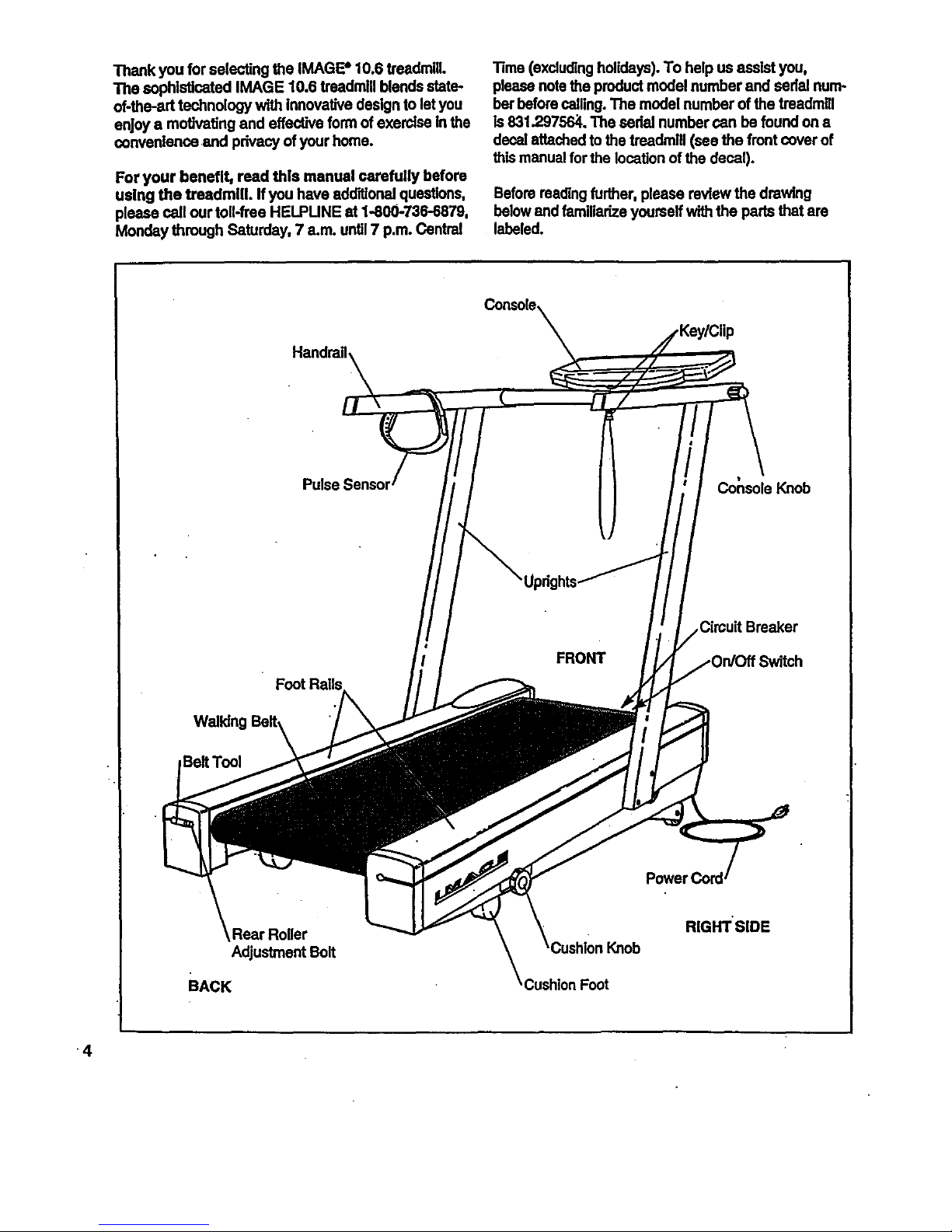
Before reading further, please review the drawing
belowand familiarize yourself with the pads that are
labeled.
Console,
Handrail
Co_soleKnob
FRONT
Circuit Breaker
Belt Tool
Rear Roller
Adjustment Bolt
BACK
RIGHT SIDE
4
ASSEMBLY
Assembly requires two people. Set the treadmill in a cleared area and remove all packing materials. Do not
dispose of the packing materials untilthe treadmill isfully assembled.
Assembly can be completed using the Included 7/32" ellen wrench _.
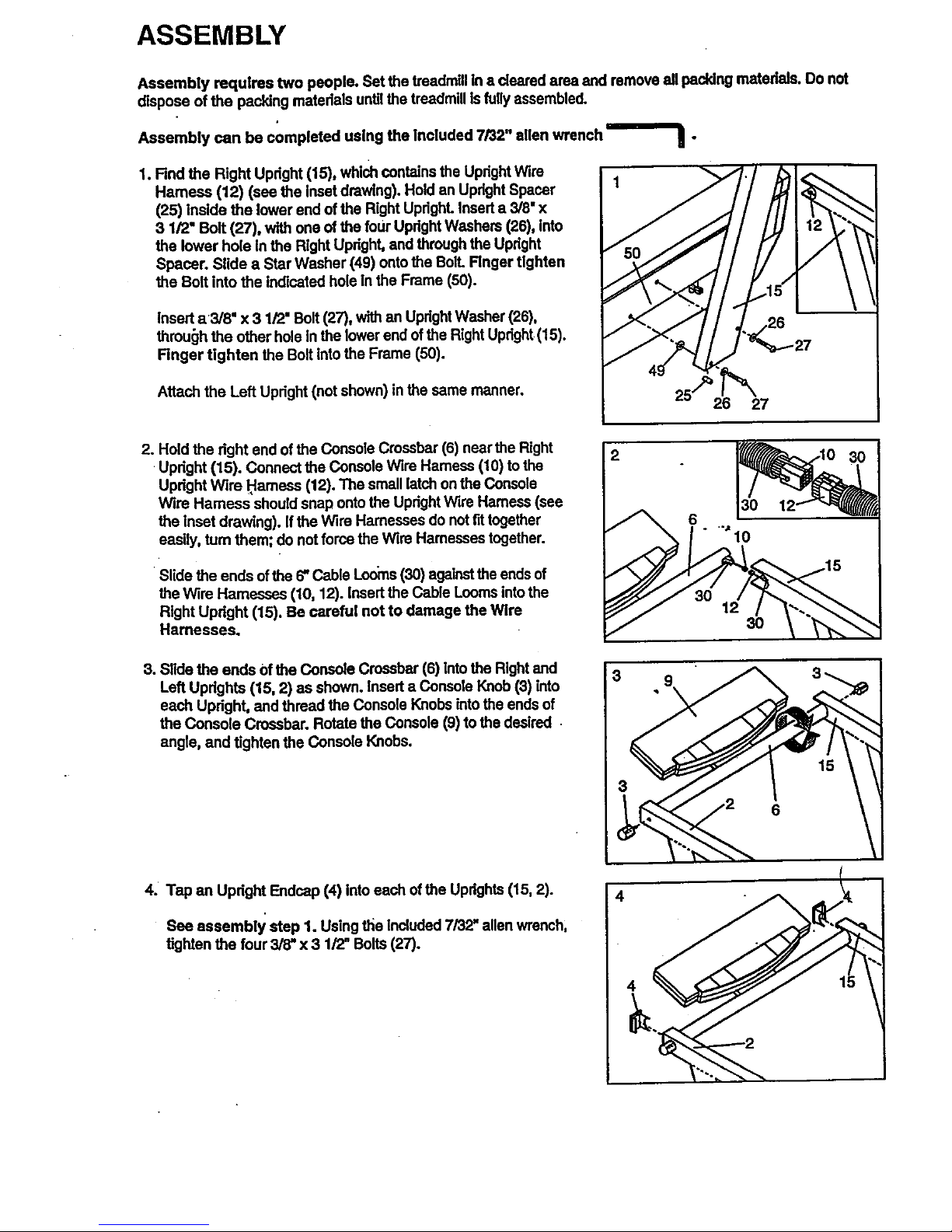
1. Find the Right Updght (15), which contains the Upright Wire
Harness (12) (see the Inset drawing). Hold an Updght Spacer
(25) inside the lower end of the Right UprighL Insed a 3/8" x
3 1/2" Bolt (27), with one of the four Updght Washers (26), into
the lower hole In the Right Updght, and through the Updght
Spacer. Slide a Star Washer (49) onto the Boll Finger tighten
the Bolt into the indicated hole In the Frame (50).
Insert a3/8" x 3 1/2" Bolt (27), with an UprightWasher (26),
through the other hole In the lower end of the Right Upright(15).
Finger tighten the Bolt into the Frame (50).
Attach the Left Upright (not shown) in the same manner.
25 26_27
2. Hold the right end of the Console Crossbar (6) near the Right
•Updght (15). Connect the Console Wire Hamess (10) to the
Updght Wire _amesa (12). The small latch on the Console
Wire Harness should snap onto the Updght Wire Harness (see
the inset drawing). If the Wire Harnesses do notfit together
easily, turn them; do not force the Wire Hamesses together.
•Slide the ends of the 6" Cable Looms (30) againstthe ends of
the wire Harnesses (10, 12). insed the Cable Looms into the
Right Updght (15). Be careful not to damage the Wire
Harnesses.
3. Slide the ends Of the Console Crossbar (6) into the Right and
Left Updghts (15, 2) as shown. Insed a Console Knob (3) into
each Upright, and thread the Console Knobs into the ends of
the Console Crossbar. Rotste the Console (9) to the desired
angte, and tighten the Console Knobs.
4. Tap an Upright Endcap (4) into each ofthe Uprights (15, 2).
See assembly step 1. Using t_e Included 7/32 =allen wrench,
tighten the four 3/8" x 3 1/2= Bolts (27).
12
30
4
15
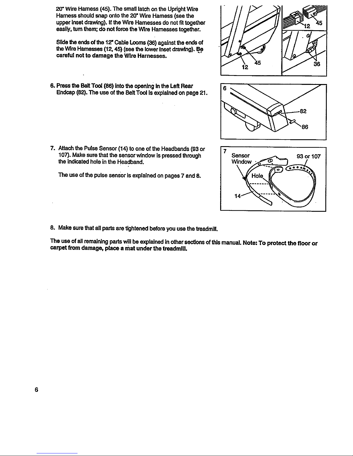
20"WireHamess(45).ThesmalllatchontheUpdghtWire
Hamessshouldsnapontothe 20" Wire Hamess (see the
upper inset drawing). If the Wire Harnesses do not fittogether
easily, turn them; do not force the wire Harnesses together.
Slidethe ends ofthe 12" Cable Looms (36) against the ends of
the wire Harnesses (12, 45) (see the lower Inset drawing). Bp
careful not to damage the wire Harnesses.
6. PresstheBeltTool(86) intothe openingintheLeft Rear
Endcap(82). The useofthe BeltTool Is explainedonpage21.
7. Attach the Pulse Sensor (14) to one of the Headbands (93 or
107). Make sure that the sensor window is pressed through
the indicated hole in the Headband.
The use of the pulse sensor is explained on pages 7 and 8.
7
Sensor
Window
93 or 107
8. Make sure that all parts are tightened before you use the treadmill.
The use of all remaining parts will be explained In other sections of thIs manual. Note: To protect the floor or
carpet from damage, place a mat under the treadmUl.
HOW TO USE THE PULSE SENSOR
The treadmill features a state-of-the-ad cordless pulse
sensor, specially designed for greater acoumcy, com-
fort, and dureblrd.y.Please read the following
Instructions before using the pulse sensor.
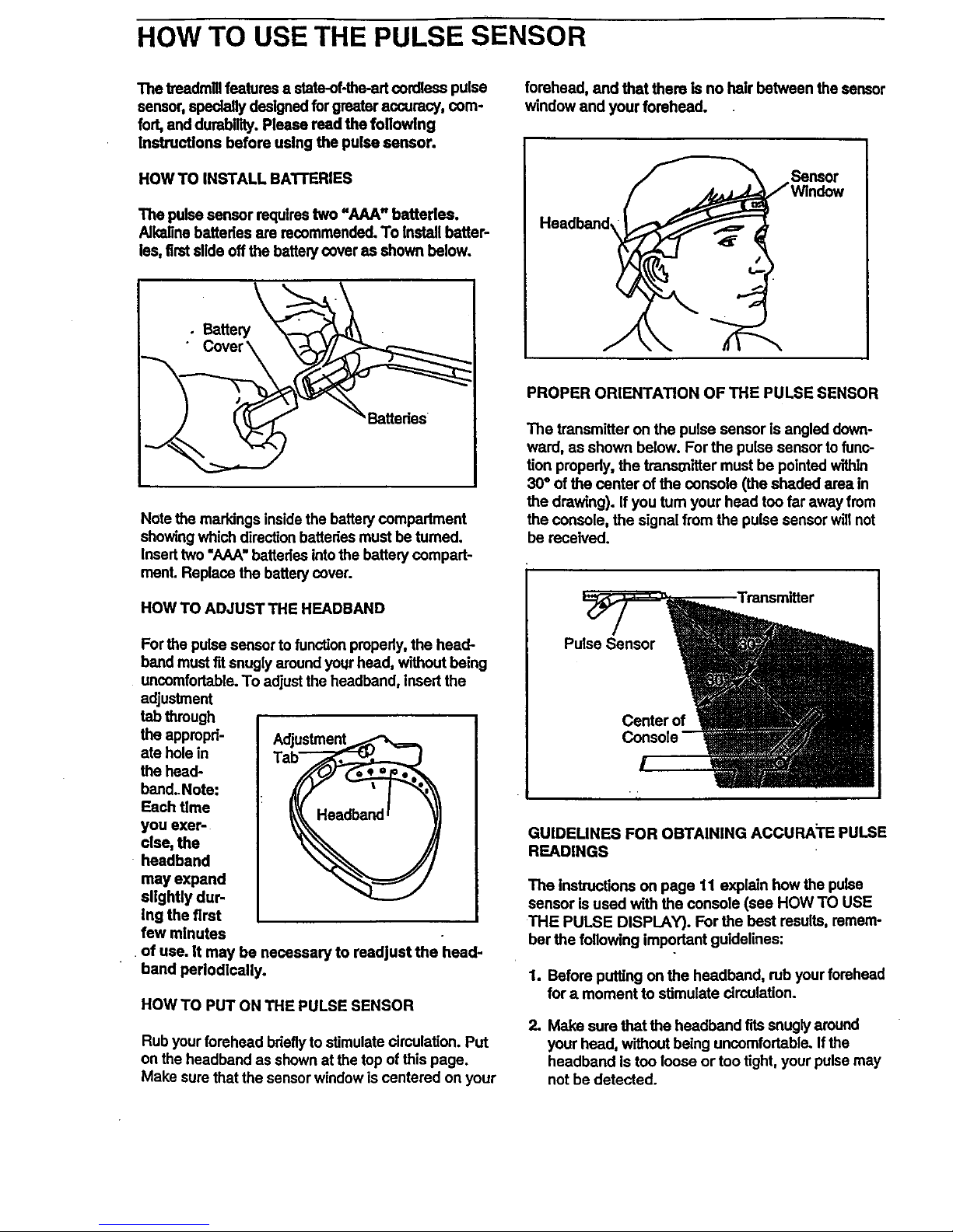
HOW TO INSTALL BATrERIES
The pulsesensorrequirestwo "AAA" batteries.
Alkalinebatteriesare recommended.To Install batter-
ias,firstslideoffthebettew coveras shown below.
J _Battedes
Note the markings inside the battery compartment
showing which direction batteries must be turned.
Insert two "AAA" batteries into the battery compart-
ment. Replace the battery cover.
HOW TO ADJUST THE HEADBAND
For the pulse sensor to function propedy, the head-
band must fit snugly around your head, without being
uncomfortable. To adjust the headband, insert the
adjustment
tab through
the appmpd-
ate hole in
the head-
band.Note:
Each time
yOU exer-
cise, the
headband
may expand
slightly dur-
Ing the first
few minutes
•of use. it may be necessary to readjust the head-
band pedodlcally.
HOW TO PUT ON THE PULSE SENSOR
Rub your forehead bdeflyto stimulate circulation. Put
on the headband as shown at the top of this page.
Make sure that the sensor window is centered on your
forehead, and that there is no hair between the sensor
window and your forehead.
Sensor
He.band,
PROPER ORIENTATION OF THE PULSE SENSOR
The transmitter on the pulse sensor is angled down-
ward, as shown below. For the pulse sensor tofunc-
tion properly, the transmitter must be pointed within
30° of the center of the console (the shaded area In
the drawing). If you tum your head too far away from
the console, the signal from the pulse sensor will not
be received.
GUIDEUNES FOR OBTAINING ACCURATE PULSE
READINGS
The Instructions on page 11 explain how the pulse
sensor is used with the console (see HOW TO USE
THE PULSE DISPLAY). For the best results, remem-
ber the following important guidelines:
1. Before putting on the headband, rub your forehead
for a.moment to stimulate circulation.
2. Make sure that the headband tits snugly around
your head, without being uncomfortable.. If the
headband Is too loose or too tight, your pulse may
not be detected.
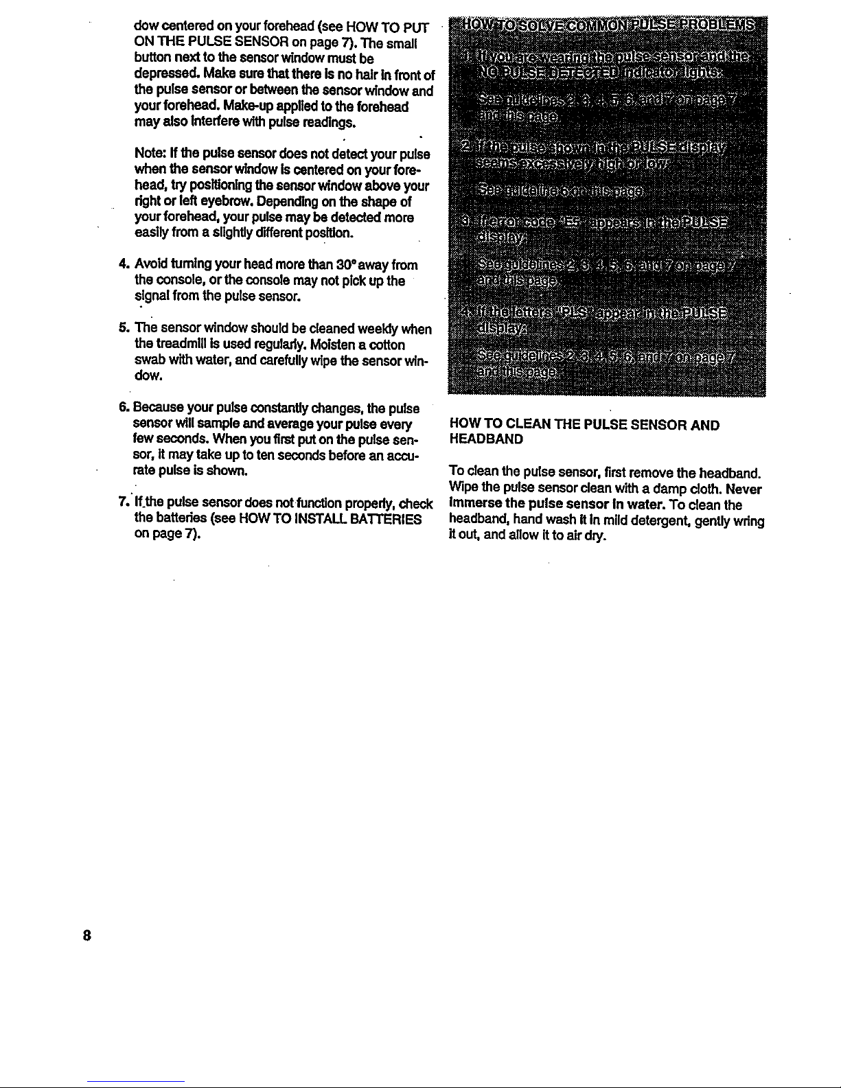
dowcenteredonyourforehead (see HOW TO PUT
ON THE PULSE SENSOR on page 7). The small
button next to the sonsor window must be
depressed. Make sure that there is no hair In frontof
the pulse sensor or between the sensor window and
your forehead. Make-up appliedto the forehead
may also Interfere with pulse readings.
Note: If the pulse sensor does not detect your pulse
when the sensor window Is centered on your fore-
head, try positioningthe sensor window above your
dght or left eyebrow. Depending on the shape of
your forehead, your pulse may be detected more
easily from a slightlydifferent position.
4.,Avoid turning your head more than 30°away from
the console, orthe console may not pick up the
signal from the pulse sensor.
The sensor window should be cleaned weekly when
the treadmill Is used regulsdy. Moisten a cotton
swab with water, and carefully wipe the sensor win-
dow.
6. Because your pulse constantly changes, the pulse
sensor will sample and average your pulse every
few seconds. When you first put on the pulse sen-
sor, it may take up to ten seconds before an accu-
rate pulse is shown.
7.'If the pulse sensor does not function properly, check
the batteries (see HOW TO INSTALL BATTERIES
on page 7).
HOW TO CLEAN THE PULSE SENSOR AND
HEADBAND
To dean the pulse sensor, first remove the headband.
Wipe the pulse sensor dean with a damp cloth. Never
Immerse the pulse sensor in water. To dean the
headband, hand wash it in mild detergent, gently wring
it out, and allow it to alr dry.
8
OPERATION AND ADJUSTMENT
THE PERFORMANT LUBE _ WALKING BELT
Your treadmill features a walidng belt coated with
PERFORMANT LUBE _, a high-performance lubdcent.
IMPORTANT: Never apply silicone spray or other
substances to the walking belt or the walking plat-
form. They will deteriorate the walking belt and
cause exceesive wear.
HOW TO PLUG IN THE POWER CORD
dsk of electric shock. This product is equipped with a
cord having an equipment-grounding conductor and a
grounding plug. Plug the power cord Into a surge
protector, and plug the surge protector Into an
appropriate outlet that !s propedy Installed end
grounded In accordance with all local codes and
ordinances.
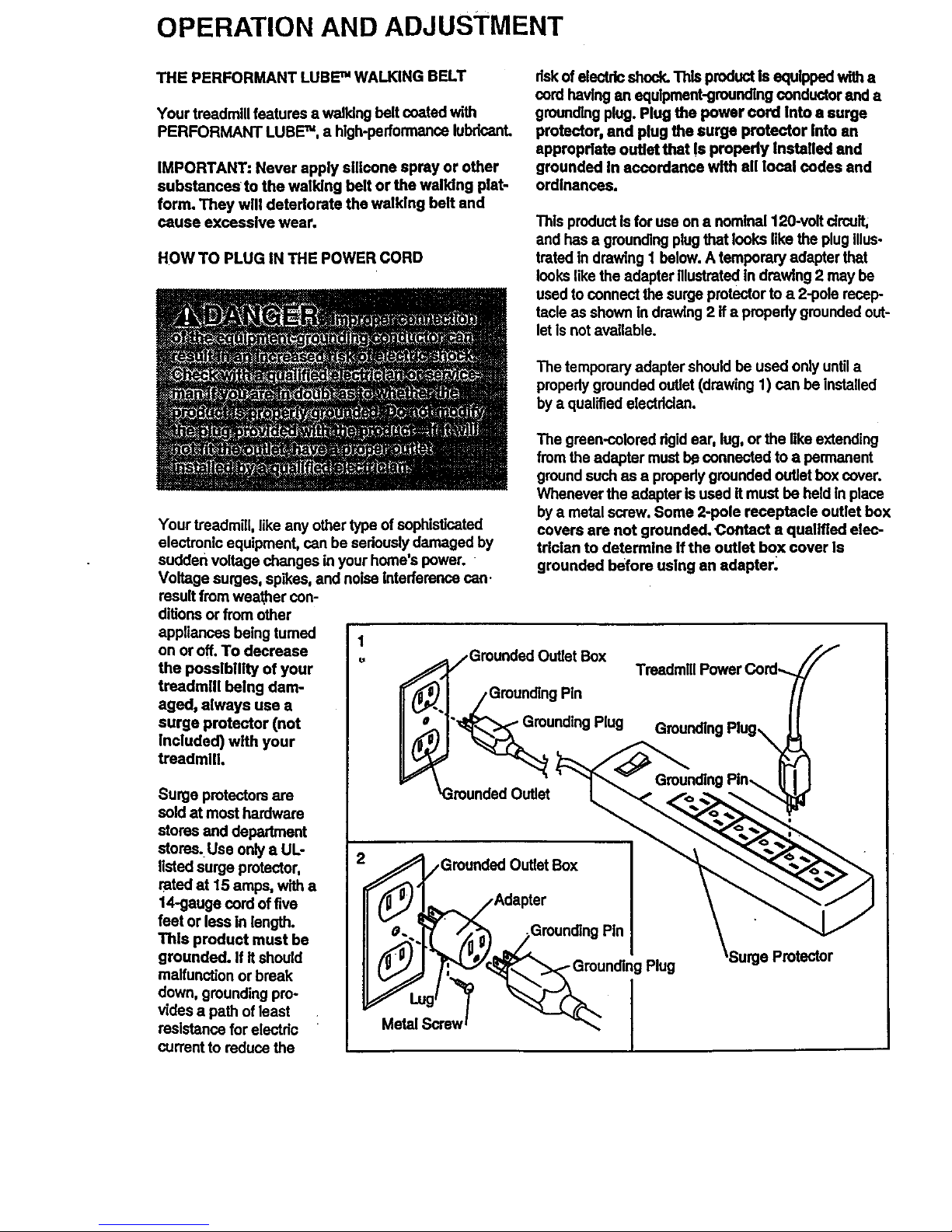
This product isfor use on a nominal 120-volt drcuif,
and has a grounding plug that looks like the plug Illus-
trated in drawing 1 below. A temporary adapter that
lookslike the adapter illustrated in drawing 2 may be
used to connect the surge protector to a 2-pole recep-
tacle as shown in drawing 2 if a propedy grounded out-
let is not available.
The temporary adapter should be used only until a
propedy grounded outlet (drawing 1) can be installed
by a qualified eisctddan.
Your treadmill, like any other type of sophisticated
electronic equipment, can be seriously damaged by
sudden voltage changes in your home's power. -
Voltage surges, spikes, and noise interference can.
result from westher con-
ditions or from other
appliances being tumed 1
on or off. To decrease
the poesibUity of your
treadmill being dam-
aged, always use a
surge protector (not
Included) with your
treadmUl.
Surge protectors are
sold at most hardware
stores and department
stores.Use only a UL-
listed surge protector,
rated at 15 amps, with a
14-gauge cord offive
feet or lass In length.
This product must be
grounded. If if should
malfun_on or break
down, grounding pro-
vides a path of least
resistance for electdo
current to reduce the
The green-colored dgid ear, lug, or the like extending
from the adapter mustb¢ connected to a permanent
ground such as a propady grounded outlet box cover.
Whenever the adapter is used it must be held In place
by a metal screw. Some 2-pole receptacle outlet box
covers are not grounded. Contact a qualified elec-
trician to determine If the outlet box cover Is
grounded before using an edaptar.
)utlet Box
=Pin
Plug
Protector
j,GrounGrOundedOutlet Box
Adapter
dlng Pin
, o oun o0 ,u0
 Loading...