

Image 831297562 Owner’s Manual
i'MAG
SEa/AIR8
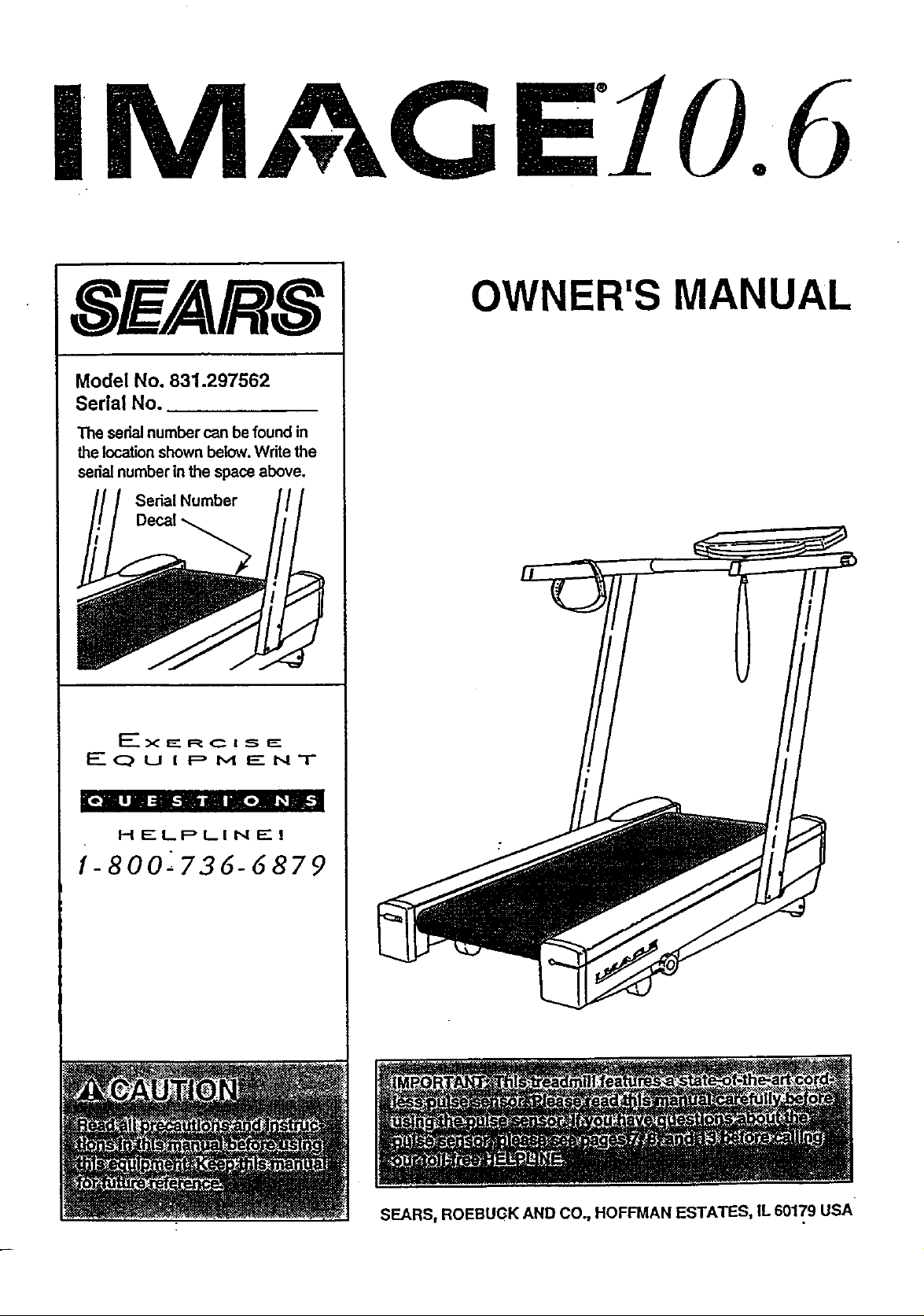
Model No. 831.297562
Serial No.
The serial number can be found in
the location shown below.Write the
serial number in the space above.
Serial Number
Decal
10.6
OWNER'S MANUAL
EXERCISE
EQUIPMENT
[t.lll =lib.'ill Ill libel _
HELPLINE!
1-800-736-6879
SEARS, ROEBUGK AND CO., HOFFMAN ESTATES, IL 60179 USA
TABLE OF CONTENTS
FULL ONE YEAR WARRANTY ....
IMPORTANT PRECAUTIONS .......
BEFORE YOiJ BEGIN ........................
ASSEMBLY .................................
HOW TO USE THE PULSE SENSOR .............
OPERATION AND ADJUSTMENT ............ . ..
MANUAL MODE OPERATION ................... . .
HOW TO CONTROL'THE SPEED ................
HOW TO CONTROL THE INCLINE ..............
HOW TO USE THE FAT CALORIE MONITOR ....................
PROGRAM MODE OPERATION ..................................
HOW TO USE A PRESET WORKOUT PROGRAM .................
HOW TO USE THE PULSE MODE ..............................
HOW TO USE THE FAT BURN AND FAT BURN PLUS PROGFLAMS . . .
HOW TO USE THE FITNESS TEST PROGRAM ....................
HOW TO CREATE CUSTOM WORKOUT PROGRAMS ..................................... 16
HOW TO USE A CUSTOM WORKOUT PROGRAM ........................................ 17
TROUBLE-SHOOTING AND STORAGE ....................................................... .2.0
CONDITIONING GUIDELINES .................. . . . ,., .22.
ORDERING REPLACEMENT PARTS .......................................... .. . ... . . Back Cover
• , ••••.••. • • •o .,60••4•QO•OQ•O,O,,O.eO0 ,t,• •• • Ol,,,•_ •e4,o• •
o,, • • • ,t, • • •
• QeO,t_ •o O,Ot,•8,••O,•••••,•Q•,,•••,O*•Q°_
• •,•°o. = , .,e°,o,°•_ooo_oo•=,,_°=5
...... .]2]]2]i........,....i.........9
• o.,=..-..e.q.t•.4o..• ole_l_ol.•el=oQ_l
• ,,• =,o Qa. OO.Q,9,,,
o= _,*•o
o• • •o
............... 11
............... 11
............... 12
............... 12
.............. 12
............... la
Note: There Is an EXPLODED DRAWING and PART LIST attached to the center of this manual Save the
EXPLODED DRAWING and PART LIST for future reference=
*I FULL ONE YEAR WARRANTY l
For one (1) year from.the date of p_rchase, if failure occursdue to defect in material or workmanship in
this SEARS TREADMILL EXERCISER, contact the nearest SEARS See/ice Center throughoutthe
United States and SEARS willrepair or replace the TREADMILL EXERCISER, free ofcharge.
ThLswarrantydoes notapply when the TREADMILL EXERCISER is used commercially or for rental pur-
poses.
Thiswarranty gives you specJ'ficlegal dghts, and you may also have other dghts which vary from state
tostate.
SEARS, ROEBUCK AND CO., DEPT• 817WA, HOFFMAN ESTATES, IL 60179
E
2

BEFORE YOU BEGIN
Thank you for sel_=ctingthe IMAGE" 10.6 treadmill.
•The sophisticated IMAGE 10.6 treadmill blendsstate-
of-the-art technology with innovativedesignto letyou
enjoy a motivatingand effective form of exercise in the
convenlence and privacy ofyour home.
For your benefit, read this manual carefully before
using the treadmill. Ifyou have add'dionalquestions,
please call our toll-free HELPUNE at 1-800-736-6879,
Monday thrf_ughSaturday, 7 a.m. until7 p.m. Central
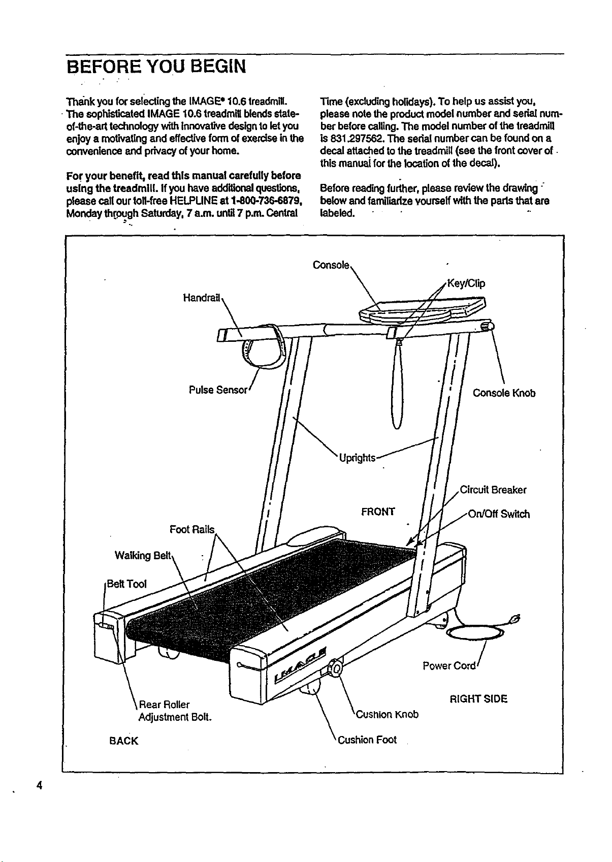
Handrail,
Pulse
Time (excluding holidays). To help us assist you,
please note the productmodel number and sedal num-
ber before calling. The model number of the treadmill
is 831,297562. The seda[ number can be found on a
decal attached to the treadmill (see the front cover of
this maneai for the location of the decal).
Before reading further, please review the drawing "
below and famili,'idzeyourself with the parts that are
labeled.
Console,
Console Knob
E]eltTool
BACK
Rear Roller
Adjustment Bolt.
Circuit Breaker
FRONT
RIGHT SIDE
Knob
;ushion Foot
4

ASSEMBLY
Assembly requires two people. Set the treadmill in a cleared area and remove all packing materials. Do not
dispose of the packing materials until the treadmill Is fully assembled.
Assembly can be completed using the Included 7/32" allen wrench _.
1. Find the Right Upright(15), which contains the Upright Wire
Harness (12) (sea the inset drawing), Hold an Upright Spacer
(25) Inside the lower end of the Right Upright. Insert a 3/8" x
3 1/2" Bolt (27), with one of the four Upright Washers (26), Into
the lower hola in the Right Upright, and through the Updght
Spacer. Slide a Star Washer (49) onto the Boll Finger tighten
the Boltinto the indicated hole in the Frame (50).
Insert a 3/8" x 3 1/2" Bolt (27), with an Upright Washer (26),
through the other hole in the lower end of the Right Upright (15).
Finger tighten the Bolt into the Frame (50).
7 •
Attach the Left Upright (not shown) in the same manner.
2. Hold the right end of theConsole Crossbar (6) near the Right
Upright (15). Connect the Console Wire Hamess (10) to the
Upright Wire Harness (12). The small latch on the Console
W',raHarness should snap onto the Upright Wire Hamess (see
the Inset drawing). If the Wire Harnesses do not fit together
easily,,turnthem; do not force the Wire Harnesses together.
Slide the ends of the 6"Cable Looms (30) against the ends of
the Wire Harnesses (10, 12). Insert the Cable Looms into the
Right Upright (15). Be careful not to damage the Wire
Harnesses.
3. Slide the ends of the Console Crossbar (6) into the Right and
Left Updgh_e(15, 2) as shown. Insert a Console Knob (3) into
each Upright, and thread the Console Knobs into the ends of
the Console Crossbar. Rotate the Console (9) to the desired
angle, and tighten the Console Knobs.
26 27
2
6
12
30
3 9
15
3
4. Tap an Upright Endcap (4) into each of the Uprights (15, 2).
See assembly step 1. Using the included 7/32" allen wrench,
tighten the four 3/6. x 3 1/2" Bolts (27).
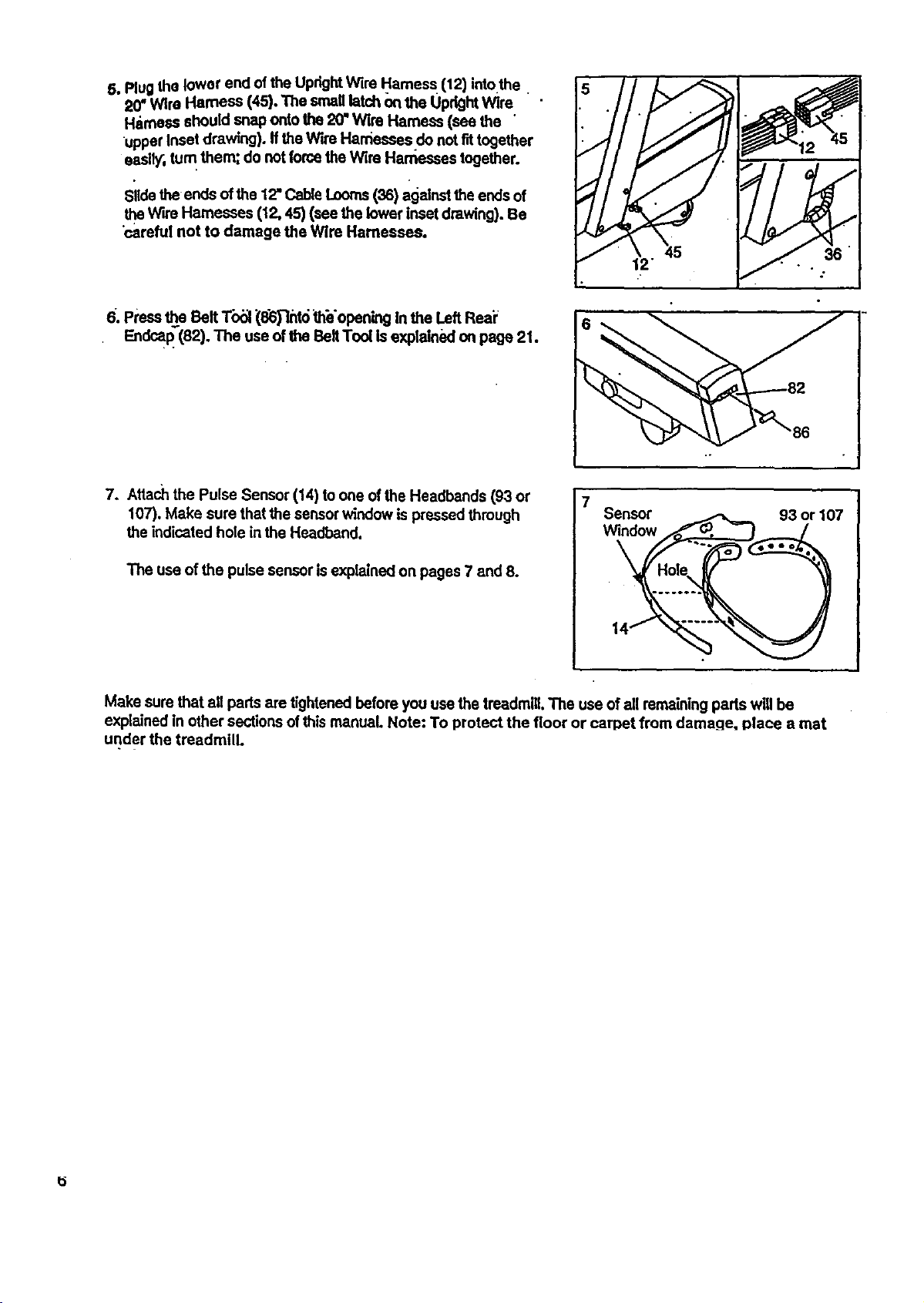
5.PlugtheIoworendoftheUprightWireHarness(12)intothe
20"WireHamese(45).Thesmaglatchonthe Uprightwire
Harness should snap onto the 20"Wire Harness (see the
upper Inset drawing), ffthe Wire Harnesses do not f_ together
easW, turn them; do not forcethe wire Harasses together.
Slidethe ends of the 12"Cable Looms(36) againsttheends of
theWire Harnesses (12, 45) (see the lower inset drawing). Be
"carefulnot to damage the Wire Harnesses.
6. Press_e Belt T'o_l(8_"mt6 _h_'opening In the Left Reai;
Endcap"(82). The use of the Belt Tool is explained on page 21.
7. Attach the Pulse Sensor (14) to one of the Headbands (93 or
107). Make sure that the sensor window is pressed through
the indicated hole in the Headband.
The use of the pulse sensor is explained on pages 7 and 8.
Make sure that all pads are tightenedbefore you use the treadmill, The use of all remainingparts will be
explained in other sections of this manual. Note: To protect the floor or carpet from damage, place a mat
under the treadmill.
7
Sensor
window
93 or 107
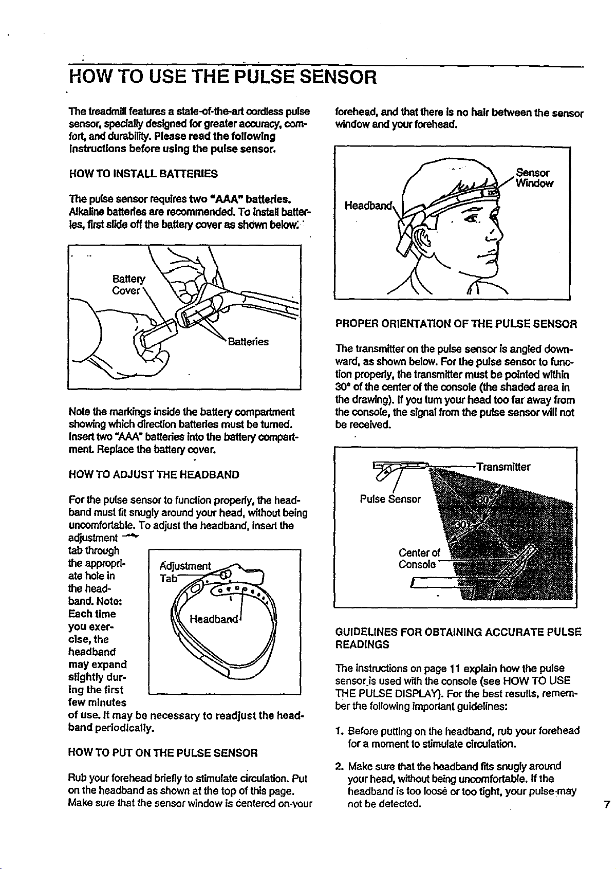
How TO USE THE PULSE SENSOR
The treadmill features a state-of-the-art cordlesspulse
sensor, specially designed for greater accuracy, com-
fort, and durability. Please read the following
Instructions before using the pulse sensor.
HOW TO INSTALL BATI'ERIES
The pulsesensor requirestwo "AAA" battedea.
Alkaline battedea are recommended. To Install batter-
lss, first slide off the batten/cover as shown below; :
\ tteries
Note the markings inside the battery compartment
showing which direction batteries must be tumed.
Insed two "AAA" batteries into the battery compart-
manL Replace the battery cover.
forehead, and that there is no hair between the sensor
window and your forehead.
_ensor
Headband,
PROPER ORIENTATION OF THE PULSE SENSOR
The transmitter on the pulse sensor is angled down-
ward, as shown below. For the pulse sensor to func-
tionproperly0the transmitter must be pointed within
30° of the center of the console (the shaded area in
the drawing). If you turn your head too far away from
the console, the signal from the pulse sensor wli! not
be received.
HOW TO ADJUST THE HEADBAND
For the pulse sensor to function properly, the head-
band mustfit snugly around your head, without being
uncomfortable. To adjustthe headband, insert the
adjustment
tab through
the appropri- Adjustment
ate hole in
the head-
band. Note:
Each time
you exer-
cise, the
headband
may expand
slightly dur-
Ing the first
few minutes
of use. it may be necessary to readjust the head-
band perlodlcally.
HOW TO PUT ON THE PULSE SENSOR
Rub your forehead briefly to stimulate circulation. Put
on the headband as shown at the top of this page.
Make sure that the sensor window is Centered on-your
Pulse Sensor
Center of
GUIDELINES FOR OBTAINING ACCURATE PULSE
READINGS
The instructions on page 11 explain how the pulse
sensor is used with the console (see HOW TO USE
THE PULSE DISPLAY). For the best results, remem-
ber the following important guidelines:
1. Before putting on the headband, rub your forehead
for a moment to stimulate circulation.
2. Make surethat the headband fits snugly around
your head, withoutbeing uncomfortable. If the
headband is too looseor too tight, your pulse-may
not be detected. 7
f
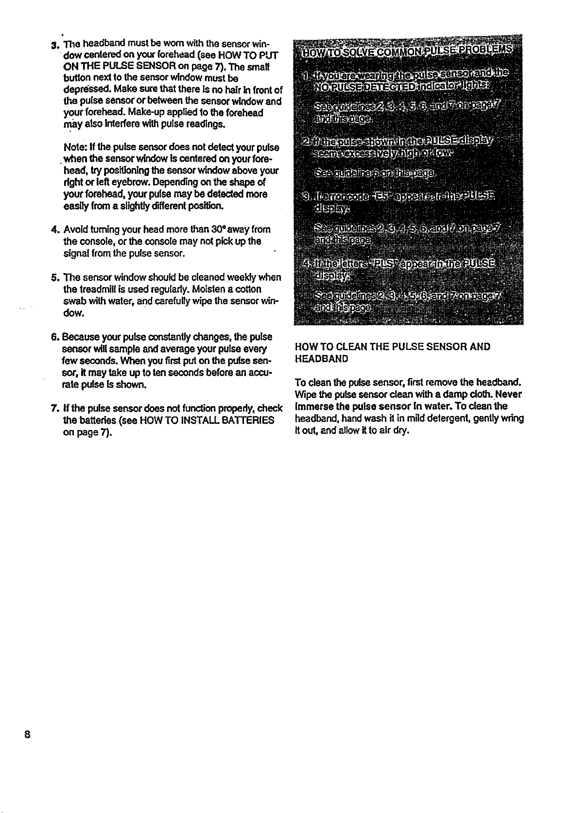
01.The headband must be wornwith the sensor win-
dow centered on your forehead (see HOW TO PUT
ON THE PULSE SENSOR on page 7). The small
button nextto the sensor window must be
depressed. Make sure that there Is no hair In frontof
the pulse sensor or between the sensorwindow and
your forehead. Make-up applied to the forehead
may also Interfere withpulse readings.
Note: If the pulse sensordoes not detect your pulse
•when the sensor windowis centered on your fore-
heed, trypositioningthe sensorwindow above your
right or left eyebrow. Depending on the shape of
your forehead, your pulsemay be detected more
easily from a slightly different position.
4. Avoid turning your head more than 30°away from
the console, or the console may not pick up the
signal from the pulse sensor.
5. The sensor window shouldbe cleaned weekly when
the treadmill is used regularly. Moisten a cotton
swab with water, and carefullywipethe sensorwin-
dow.
6. Because your pulse constantlychanges, the pulse
sensor will sample and average your pulse every
few seconds. When you first put on the pulse sen-
sor, it may take up to ten seconds before an accu-
rate pulse Is shown.
7. If the pulse sensor does not functionproperly,check
the batteries (see HOW TO INSTALL BATTERIES
on page 7).
HOW TO CLEAN THE PULSE SENSOR AND
HEADBAND
To clean the pulsesensor, first remove the headband.
Wipe the pulse sensor dean with a damp cloth.Never
Immerse the pulse sensor In water. To dean the
headband, handwash itin mild detergent, gentlywring
it out, and allow it to air dry.
8
OPERATION AND ADJUSTMENT
THE PERFORMANT LUBE TM WALKING BELT
Your treadmill features a walking belt coated with
PERFORMANT LUSETM, a high-performance lubricant.
IMPORTANT: Never apply silicone spray or other
substances to the walking belt or the walldng plat-
form. They will deteriorate the walking belt end
cause excessive wear.
HOW TO PLUG IN THE POWER CORD
Your treadmill, like any other type of sophisticated
electronic equipment, can be seriously damaged by
sudden voltage changes in your home's power.
Voltage surges, spikes, and noise interference can
resultfrom weather con-
ditions or from other
appliances being turned 1
on or off. To decrease
the possibility of your
treadmill belg._ dam-
aged, always use a
surge protector (not
Included) with your
treadmlll.
risk of electric shock, This product is equipped with a.
cord having an equlpment-grounding conductor and a
grounding plug. Plug the power cord into a surge
protector, and plug the surge protector into an
appropriate outlet that Is properly Installed and
grounded in accordance with all local codes and
ordinances.
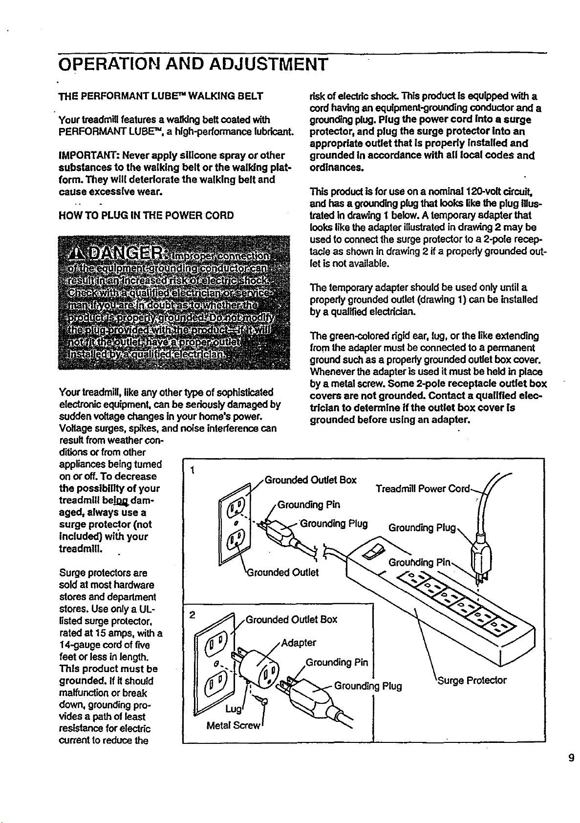
This product is for use on a nominal 120-volt circuit,
and has a grounding plug that looks like the plug Illus-
trated in drawing 1 below. A temporary adapter that
locks like the adapter illustrated in drawing 2 may be
used to connect the surge protector to a 2-pole recep-
tacle as shown in draw',ng2 if a properly grounded out-
let is not available.
The temporary adapter should be used only until a
properly groundedoutlet (drawing 1) can be installed
by a qualified electrician.
The green-colored dgid ear, lug, or the like extending
from the adapter must be connected to a permanent
ground such as a properly grounded outlet box cover.
Whenever the adapter is used it must be held in place
by a metal screw. Some 2-pole receptacle outlet box
covers are not grounded. Contact a qualified elec-
trician to determine If the outlet box cover is
grounded before using an adapter.
Treadmill Power Cord--.
Grounding
Surge protectorsare
sold at most hardware
stores and department
stores. Use only a UL-
listed surge protector,
rated at 15 amps, with a
14-gauge cord of rNe
feet or less in length.
Thls product must be
grounded. If itshould
malfunction or break
down, grounding pro-
vides a path of least
resistance for electdc
current to reduce the
Grounded Outlet Box
/Adapter
_.. ;_/_ __Grounding Pin
Plug 'Surge Protector
_L'u g_'_ _°_/_u ndii g
Metal Screw _ J
 Loading...