

Image 6.5, IMSY59400 User Manual
odel No. IMSY59400
Visit our website at
www.imagefitness.com
new products, prizes,
fitness tips, and much more!
M
Serial No.
he serial number is found in the
T
location shown below. Write the
serial number in the space above.
Serial Number Decal
QUESTIONS?
As a manufacturer, we are
committed to providing complete customer satisfaction. If
you have questions, or if there
are missing parts, we will guarantee complete satisfaction
through direct assistance from
our factory.
TO AVOID UNNECESSARY
DELAYS, PLEASE CALL
DIRECT TO OUR TOLL-FREE
CUSTOMER HOT LINE. The
trained technicians on our customer hot line will provide
immediate assistance, free of
charge to you.
CUSTOMER HOT LINE:
USERʼS MANUAL
1-800-999-3756
Mon.–Fri., 6 a.m.–6 p.m. MST
CAUTION
Read all precautions and instructions in this manual before using
this equipment. Save this manual for future reference.

Table of Contents
Important Precautions . . . . . . . . . . . . . . . . . . . . . . . . . . . . . . . . . . . . . . . . . . . . . . . . . . . . . . . . . . . . . . . . . . . . . . 2
Before You Begin . . . . . . . . . . . . . . . . . . . . . . . . . . . . . . . . . . . . . . . . . . . . . . . . . . . . . . . . . . . . . . . . . . . . . . . . . . 3
Assembly . . . . . . . . . . . . . . . . . . . . . . . . . . . . . . . . . . . . . . . . . . . . . . . . . . . . . . . . . . . . . . . . . . . . . . . . . . . . . . . . 4
Weight Resistance Chart . . . . . . . . . . . . . . . . . . . . . . . . . . . . . . . . . . . . . . . . . . . . . . . . . . . . . . . . . . . . . . . . . . . 23
Cable Diagrams . . . . . . . . . . . . . . . . . . . . . . . . . . . . . . . . . . . . . . . . . . . . . . . . . . . . . . . . . . . . . . . . . . . . . . . . . . 25
Adjustment . . . . . . . . . . . . . . . . . . . . . . . . . . . . . . . . . . . . . . . . . . . . . . . . . . . . . . . . . . . . . . . . . . . . . . . . . . . . . . 26
Trouble-shooting and Maintenance . . . . . . . . . . . . . . . . . . . . . . . . . . . . . . . . . . . . . . . . . . . . . . . . . . . . . . . . . . . 27
Ordering Replacement Parts . . . . . . . . . . . . . . . . . . . . . . . . . . . . . . . . . . . . . . . . . . . . . . . . . . . . . . . . . Back Cover
Limited Warranty . . . . . . . . . . . . . . . . . . . . . . . . . . . . . . . . . . . . . . . . . . . . . . . . . . . . . . . . . . . . . . . . . . Back Cover
Note: A Part List/Exploded Drawing and a Part Identification Chart are attached in the center of this manual.
Important Precautions
WARNING: To reduce the risk of serious injury, read the following important precautions
before using the home gym.
1. It is the responsibility of the owner to ensure
that all users of the home gym are adequately
informed of all precautions.
2. Read all instructions in this manual and in
the accompanying literature before using the
home gym.
3. The home gym is intended for home use only.
Do not use the home gym in a commercial,
rental or institutional setting.
4. Use the home gym only on a level surface.
Cover the floor or carpet beneath the home
gym for protection.
5. Inspect and tighten all parts often. Replace
any worn parts immediately.
6. Make sure that the cables remain on the pulleys at all times. If the cables bind while you
are exercising, stop immediately and make
sure the cables are on all of the pulleys.
7. Always stand on the foot plate when performing an exercise that could cause the home
gym to tip.
8. Keep hands and feet away from moving parts.
9. Keep children under the age of 12 and pets
away from the home gym at all times.
10. Always wear athletic shoes for foot protection when exercising.
11. Never release the press arms, butterfly arms,
leg lever, lat bar, row bar, or ab strap while
weights are raised. The weights will fall with
great force.
12. If you feel pain or dizziness while exercising,
stop immediately and begin cooling down.
13. Always disconnect the lat bar, row bar, or ab
strap from the home gym when performing
exercises that do not use these attachments.
14. The decal shown
at the right has
been attached to
the home gym in
the two locations
shown on page 3.
If a decal is missing or illegible,
please call toll-free
1-800-999-3756 to
order a free
replacement decal.
Apply the decal in
the location
shown.
WARNING: Before beginning this or any exercise program, consult your physician. This is especially
important for persons over the age of 35 or persons with pre-existing health problems. Read all
instructions before using. ICON assumes no responsibility for personal injury or property damage
sustained by or through the use of this product.
2
Before You Begin
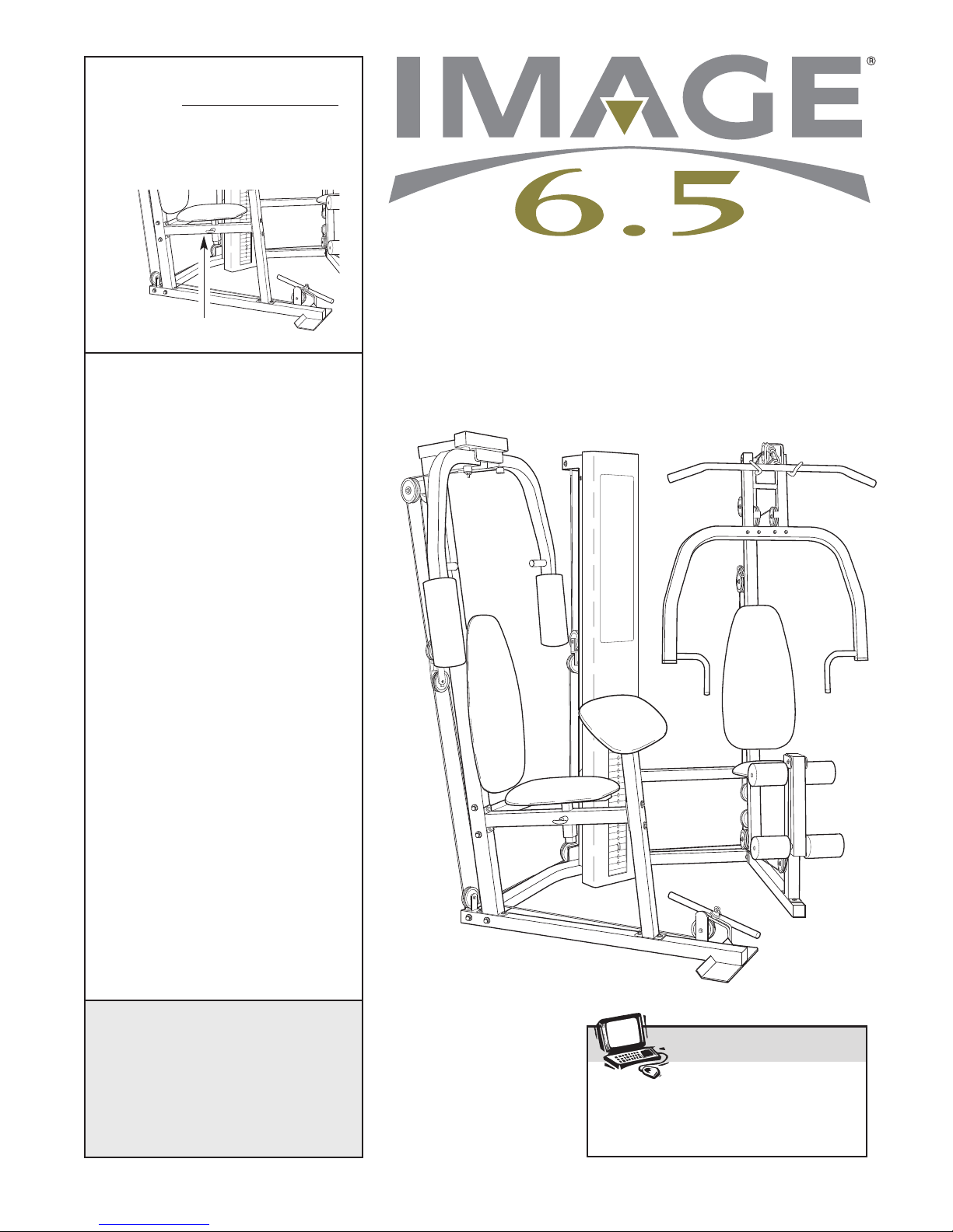
Thank you for selecting the innovative and versatile
IMAGE®6.5 home gym. The IMAGE 6.5 offers a large
election of weight stations designed to develop every
s
major muscle group of the body. Whether your goal is
to tone your body, build dramatic muscle size and
strength, or improve your cardiovascular system, the
IMAGE 6.5 will help you to achieve the results you
want.
For your benefit, read this manual carefully before
using the IMAGE
Butterfly
Arms
WARNING
DECAL
®
6.5. If you have additional ques-
Shroud
tions, please call our Customer Service Department
toll-free at 1-800-999-3756, Monday through Friday, 6
.m. until 6 p.m. Mountain Time (excluding holidays).
a
To help us assist you, please note the product model
number and serial number before calling. The model
number is IMSY59400. The serial number can be
found on a decal attached to the home gym (see the
front cover of this manual).
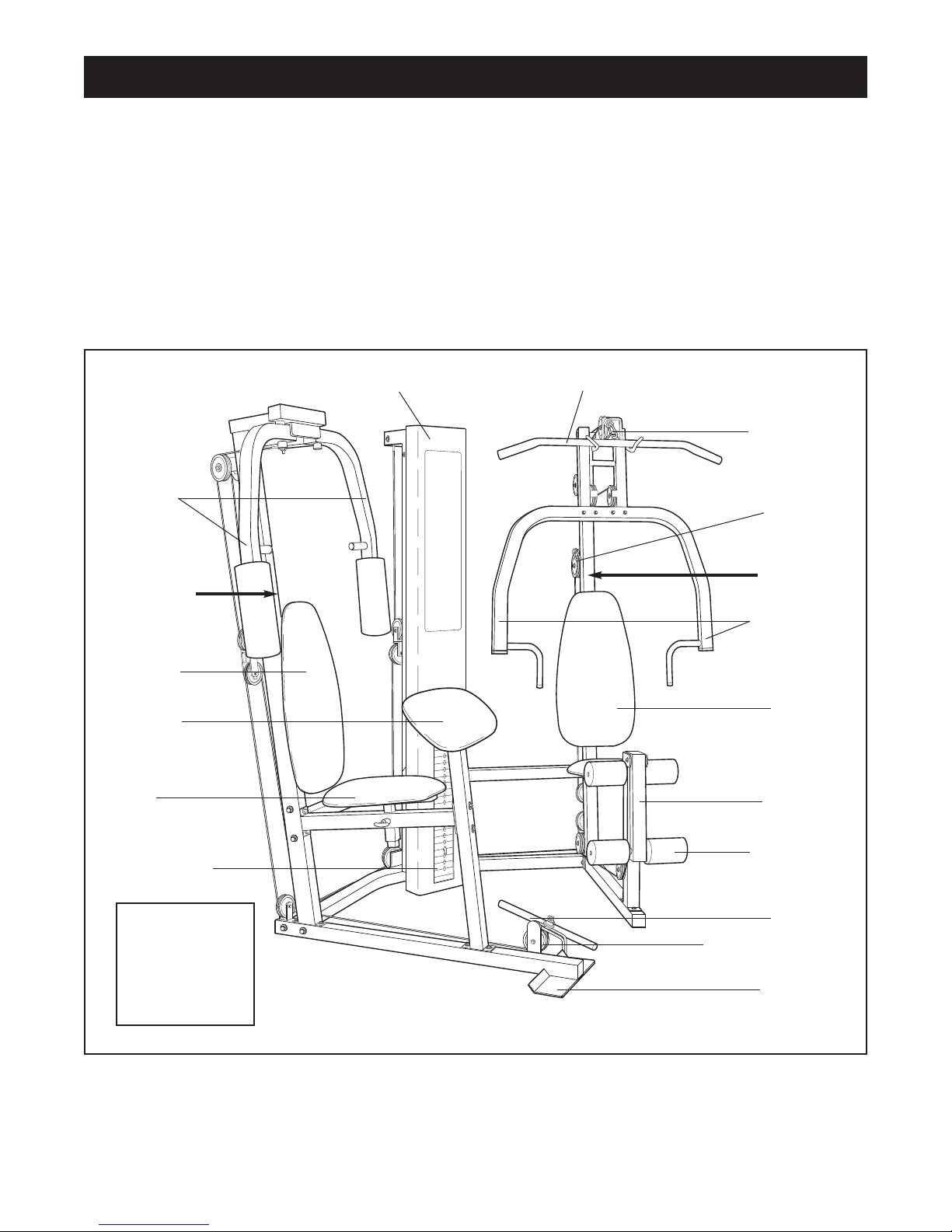
Before reading further, please familiarize yourself
with the parts that are labeled in the drawing below.
Lat Bar
High Pulley
Station
Ab Pulley
Station
WARNING
DECAL
Press Arms
Backrest
Curl Pad
Seat
Weight Stack
ASSEMBLED
DIMENSIONS:
Height: 78 in.
Width: 78 in.
Depth: 60 in.
Backrest
Leg Lever
Foam Pads
Row Bar
Low Pulley Station
Foot Plate
3
Assembly
Make Assembly Easier for Yourself!
Everything in this manual is designed to
ensure that the home gym can be assembled
successfully by anyone. Before beginning
assembly, make sure to read the information on this page; this brief introduction
will save you much more time than it takes
to read it!
Assembly Requires Two Persons
For your convenience and safety, assemble the
home gym with the help of another person.
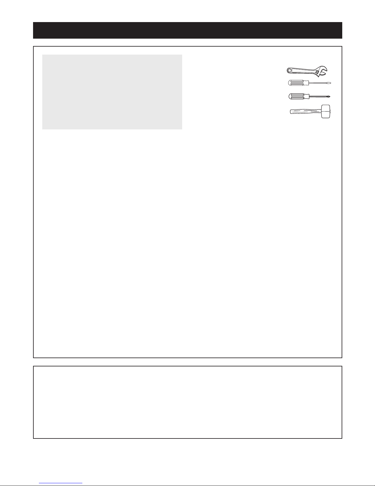
Make sure you have the following tools:
• Two (2) adjustable wrenches
• One (1) standard screwdriver
• One (1) phillips screwdriver
• One (1) rubber mallet
• You will also need grease or petroleum jelly, a
small amount of soapy water, and clear tape or
masking tape.
Note: Assembly will be more convenient if you have
a socket set, a set of open-end or closed-end
wrenches, or a set of ratchet wrenches.
Set Aside Enough Time
Due to the many features of the home gym, the
assembly process will require about six hours. By
setting aside plenty of time and by deciding to
make the task enjoyable, assembly will go smoothly.
You may want to assemble the home gym over a
couple of evenings.
Select a Location for the Home Gym
Because of its weight and size, the home gym
should be assembled in the location where it will be
used. Make sure that there is enough room to walk
around the home gym as you assemble it.
How to Unpack the Box
To make assembly as easy as possible, we have
divided the assembly process into four stages. The
parts needed for each stage are found in individual
bags. Important: Wait until you begin each stage
to open the part bag for that stage. Place all
parts of the home gym in a cleared area and
remove the packing materials. Do not dispose of
the packing materials until assembly is completed.
How to Identify Parts
To help you identify the small parts used in assembly,
we have included a PART IDENTIFICATION CHART
in the center of this manual. Place the chart on the
floor and use it to easily identify parts during each
assembly step. Note: Some small parts may have
been pre-attached. If a part is not in the part bag,
check to see if it has been pre-attached.
How to Orient Parts
As you assemble the home gym, make sure that all
parts are oriented exactly as shown in the drawings.
Tightening Parts
Tighten all parts as you assemble them, unless
instructed to do otherwise.
Questions?
If you have questions after reading the assembly
instructions, please call our Customer Service
Department toll-free at 1-800-999-3756, Monday
through Friday, 6 a.m. until 6 p.m. Mountain Time.
The Four Stages of the Assembly Process
Frame Assembly—You will begin by assembling
the base and the uprights that form the skeleton of
the home gym.
Arm Assembly—During this stage you will you
will assemble the press arms and the butterfly
arms.
Cable Assembly—During this stage you will
attach the cables and pulleys that connect the
arms to the weights.
Seat Assembly—During the final stage you will
assemble the seat and the backrest.
4
Frame Assembly
1a
28
1.
Before you begin this step, make sure that
you have read all of the information on page
. This introduction will save you much more
4
time than it takes to read it!
Open the parts bags labeled “FRAME ASSEMBLY
METAL” and “FRAME ASSEMBLY PLASTIC.”
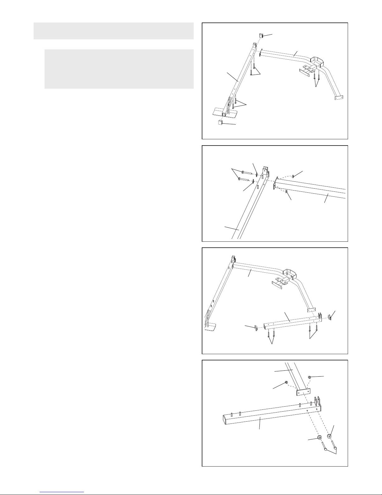
See drawing 1a. Press a 2” Square Inner Cap (28)
into each end of the Butterfly Base (4).
Insert four 5/16” x 2 1/2” Carriage Bolts (92) up
through the indicated holes in the Butterfly Base (4).
Note: If the Bolts fall out, secure them by putting
a small piece of tape over the head of each Bolt.
Place the Butterfly Base flat on the floor.
Insert two 5/16” x 2 1/2” Carriage Bolts (92) up
through the indicated holes in the Weight Base (5).
Place the Weight Base flat on the floor.
See drawing 1b. Attach the Weight Base (5) to the
Butterfly Base (4) with two 5/16” x 2 3/4” Bolts (89),
two 5/16” Washers (36), and two 5/16” Nylon
Locknuts (64).
2. See drawing 2a. Press a 2” Square Inner Cap (28)
into each end of the Press Base (6).
1b
2a
5
4
28
89
36
4
92
36
2
9
2
9
64
64
5
Insert four 5/16” x 2 1/2” Carriage Bolts (92) up
through the indicated holes in the Press Base (6).
See drawing 2b. Attach the Press Base (6) to the
Weight Base (5) with two 5/16” x 2 3/4” Bolts (89),
two 5/16” Washers (36), and two 5/16” Nylon
Locknuts (64).
2b
28
5
6
92
92
5
64
6
36
28
64
36
89
5
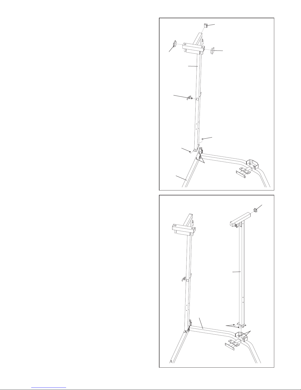
3. Press three 2” Square Inner Caps (28) into the
Butterfly Upright (1).
lace the bracket on the lower end of the Butterfly
P
Upright (1) over the indicated 5/16” x 2 1/2” Carriage
olts (92) in the Butterfly Base (4). Hand tighten two
B
5/16” Nylon Locknuts (64) onto the Bolts.
3
28
28
8
2
Thread an Adjustment Handle (85) into the indicated
hole in the Butterfly Upright (1).
4. Press a 2” Square Inner Cap (28) into the Weight
Upright (9).
1
85
64
64
92
4
4
28
Place the bracket on the lower end of the Weight
Upright (9) over the indicated 5/16” x 2 1/2” Carriage
Bolts (92) in the Weight Base (5). Hand tighten two
5/16” Nylon Locknuts (64) onto the Bolts.
9
5
64
92
6
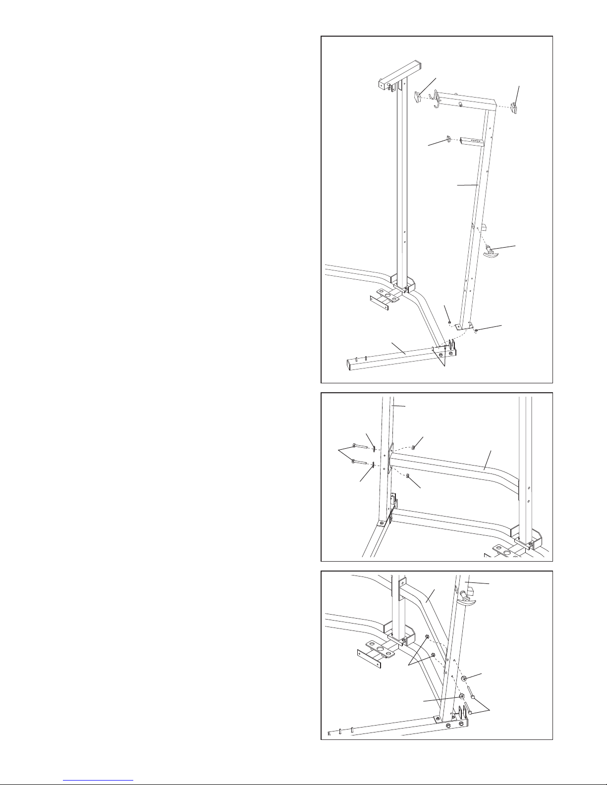
5. Press two 2” Square Inner Caps (28) into the Press
Upright (2). Press a 1 3/4” Square Inner Cap (35) into
the welded tube on the Press Upright.
Place the bracket on the lower end of the Press
pright (2) onto the indicated 5/16” x 2 1/2” Carriage
U
Bolts (92) and secure it with two 5/16” Nylon Locknuts
(64).
5
28
8
2
Thread an Adjustment Handle (85) into the indicated
hole in the Press Upright (2).
6. With a second person holding the Right Support
Frame (33) in position, attach the Right Support
Frame to the Butterfly Upright (1) with two 5/16” x 2
3/4” Bolts (89), two 5/16” Washers (36), and two 5/16”
Nylon Locknuts (64). Do not tighten the Nylon
Locknuts yet.
6
89
36
35
2
85
64
64
6
92
1
64
33
7. While a second person holds the Left Support Frame
(97) in position, attach the Left Support Frame to the
Press Upright (2) with two 5/16” x 2 3/4” Bolts (89),
two 5/16” Washers (36), and two 5/16” Nylon
Locknuts (64). Do not tighten the Nylon Locknuts
yet.
36
7
64
36
64
97
2
36
89
7
8. Attach the Right Support Frame (33) and the Left
Support Frame (97) to the Weight Upright (9) with two
5/16” x 2 3/4” Bolts (89) and two 5/16” Nylon
ocknuts (64). Tighten all Nylon Locknuts used in
L
steps 6 through 8.
8
33
64
9
89
9. Slide the Butterfly Front Leg (3) onto the indicated
5/16” x 2 1/2” Carriage Bolts (92) in the Butterfly Base
(4). Hand tighten two 5/16” Nylon Locknuts (64) onto
the Bolts. Do not tighten the Nylon Locknuts yet.
64
9
3
97
89
10. Thread an Adjustment Handle (85) into the indicated
hole in the Butterfly Seat Frame (14).
Attach the Butterfly Seat Frame (14) to the Butterfly
Front Leg (3) with two 5/16” x 2 3/4” Bolts (89), two
5/16” Washers (36), and two 5/16” Nylon Locknuts
(64). Do not tighten the Nylon Locknuts yet.
Attach the Butterfly Seat Frame (14) to the Butterfly
Upright (1) with two 5/16” x 3 3/4” Bolts (66), two
5/16” Washers (36), and two 5/16” Nylon Locknuts
(64). Tighten all Nylon Locknuts used in steps 9
and 10.
10
85
4
89
36
14
64
92
66
1
64
36
36
64
64
3
8
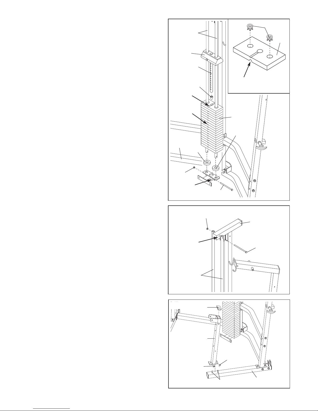
11. Place two Weight Bumpers (51) over the indicated
holes in the bracket on the Weight Base (5). Insert
the Weight Guides (15) into the holes.
See the inset drawing. Insert two Weight Inserts (94)
nto each Weight (21) as shown. Turn the Weights so
i
the large pin grooves point toward the floor.
Slide all of the included Weights (21) onto the Weight
Guides (15). Make sure that the Weights are
turned so the pin grooves are on the side shown.
Press a Weight Tube Bumper (18) into the lower end
of the Weight Tube (17). Slide the Top Weight assembly (16) onto the Weight Guides (15).
Attach the Weight Guides (15) to the welded tube on
the Weight Base (5) with a 3/8” x 6 1/2” Bolt (55) and
a 3/8” Nylon Locknut (50).
11
16
Groove
Pin
Grooves
5
15
1
51
7
18
94
21
Large Pin
Groove
21
51
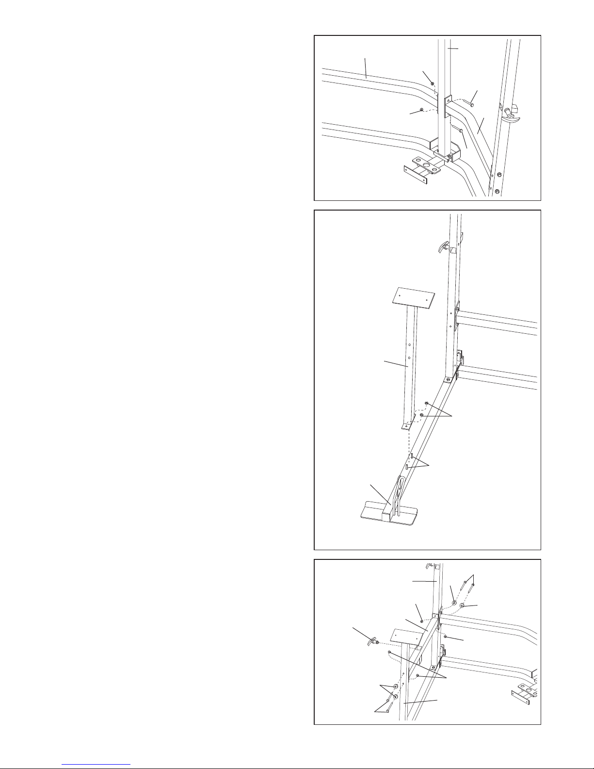
12. Attach the Weight Guides (15) to the welded tube on
the Weight Upright (9) with a 3/8” x 6 1/2” Bolt (55)
and a 3/8” Nylon Locknut (50).
13. Press a 2” Square Inner Cap (28) into the top of the
Press Front Leg (20).
Slide the Press Front Leg (20) onto the indicated
5/16” x 2 1/2” Carriage Bolts (92) in the Press Base
(6). Hand tighten two 5/16” Nylon Locknuts (64) onto
the Bolts. Do not tighten the Nylon Locknuts yet.
50
Welded
Tube
12
Welded
Tube
13
55
50
9
55
15
28
20
64
64
92
6
9
14. Hold the Press Seat Frame (7) between the Press
Front Leg (20) and the Press Upright (2) so that the
hole that is closest to the welded plate is facing the
ress Front Leg. Attach the Press Seat Frame to the
P
Press Front Leg with two 5/16” x 2 3/4” Bolts (89),
wo 5/16” Washers (36), and two 5/16” Nylon
t
Locknuts (64). Do not tighten the Nylon Locknuts
yet.
Attach the Press Seat Frame (7) to the Press Upright
(2) with two 5/16” x 3 3/4” Bolts (66), two 5/16”
Washers (36), and two 5/16” Nylon Locknuts (64).
Tighten all Nylon Locknuts used in steps 13 and
14.
14
89
36
20
64
Hole
4
6
7
64
2
6
3
66
15. Attach a Bumper (40) to the indicated hole in the
Press Front Leg (20) with a #10 x 1” Screw (80).
Press a 2” Square Inner Cap (28) into each end of
the Leg Lever (41).
Lubricate the 3/8” x 3 1/4” Bolt (62). Attach the Leg
Lever (41) to the Press Front Leg (20) with the Bolt
and a 3/8” Nylon Locknut (50). Do not overtighten
the Nylon Locknut; it must be easy to pivot the
Leg Lever.
Arm Assembly
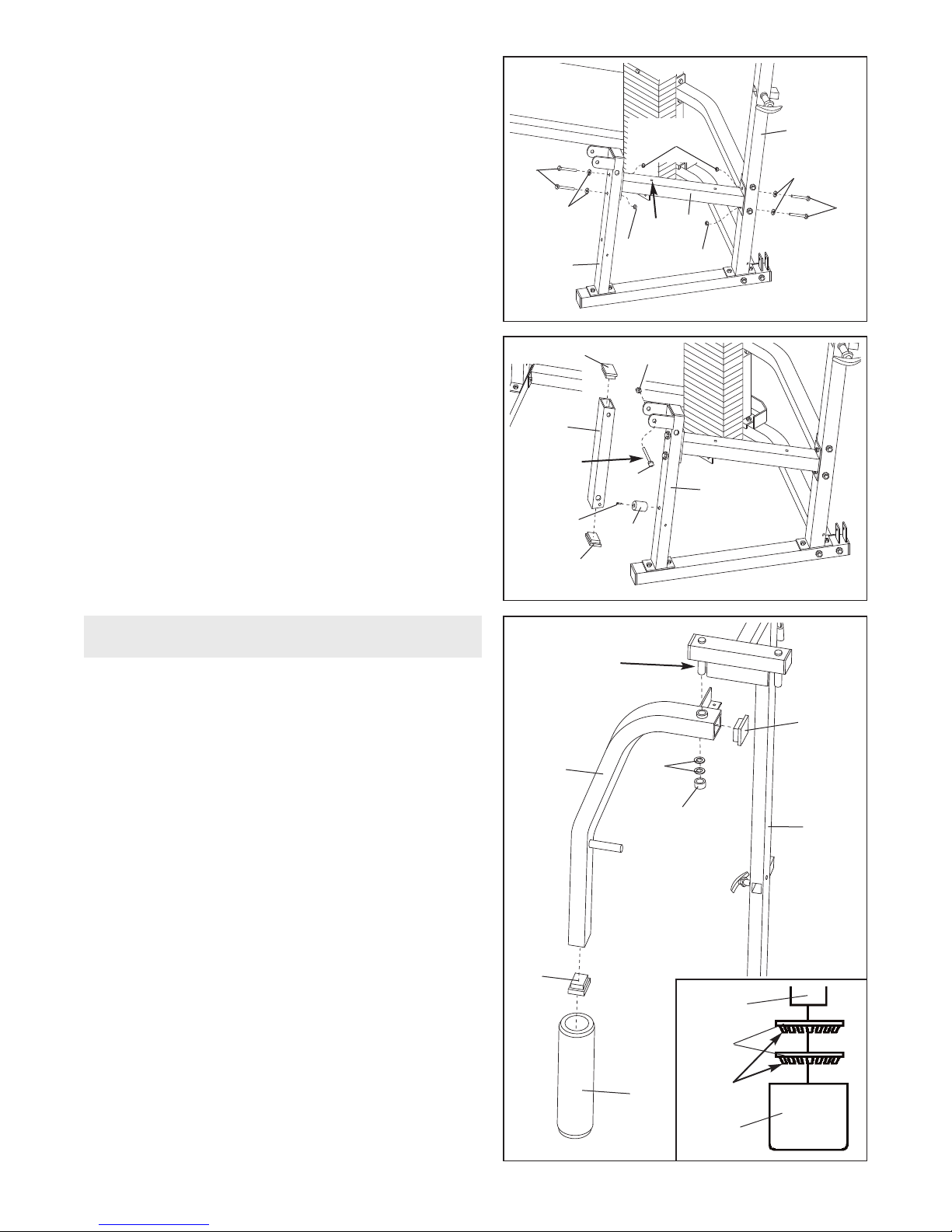
16. Press a 2” Square Inner Cap (28) into each end of
the Right Butterfly Arm (10). Wet the lower end of the
Right Butterfly Arm with soapy water. Slide a Butterfly
Foam Pad (29) onto the lower end of the Right
Butterfly Arm.
15
Lubricate
16
28
41
80
28
10
62
40
Lubricate
Axle
50
20
28
31
Lubricate the indicated axle on the Butterfly Upright
(1). Orient the Right Butterfly Arm (10) as shown and
slide it onto the axle. Secure the Butterfly Arm with
two Retainer Rings (31) and a 1” Round Outer Cap
(38) in the following way: Place the Retainer Rings
on top of the inverted Round Outer Cap, making
sure that the teeth on the Retainer Rings bend
towards the Round Outer Cap as shown in the
inset drawing. Gently tap the Round Outer Cap
onto the axle with a hammer.
Attach the Left Butterfly Arm (11, not shown) on the
opposite side by following the procedure described
above.
10
28
29
38
1
Axle
31
Teeth
38
 Loading...