

Page 1
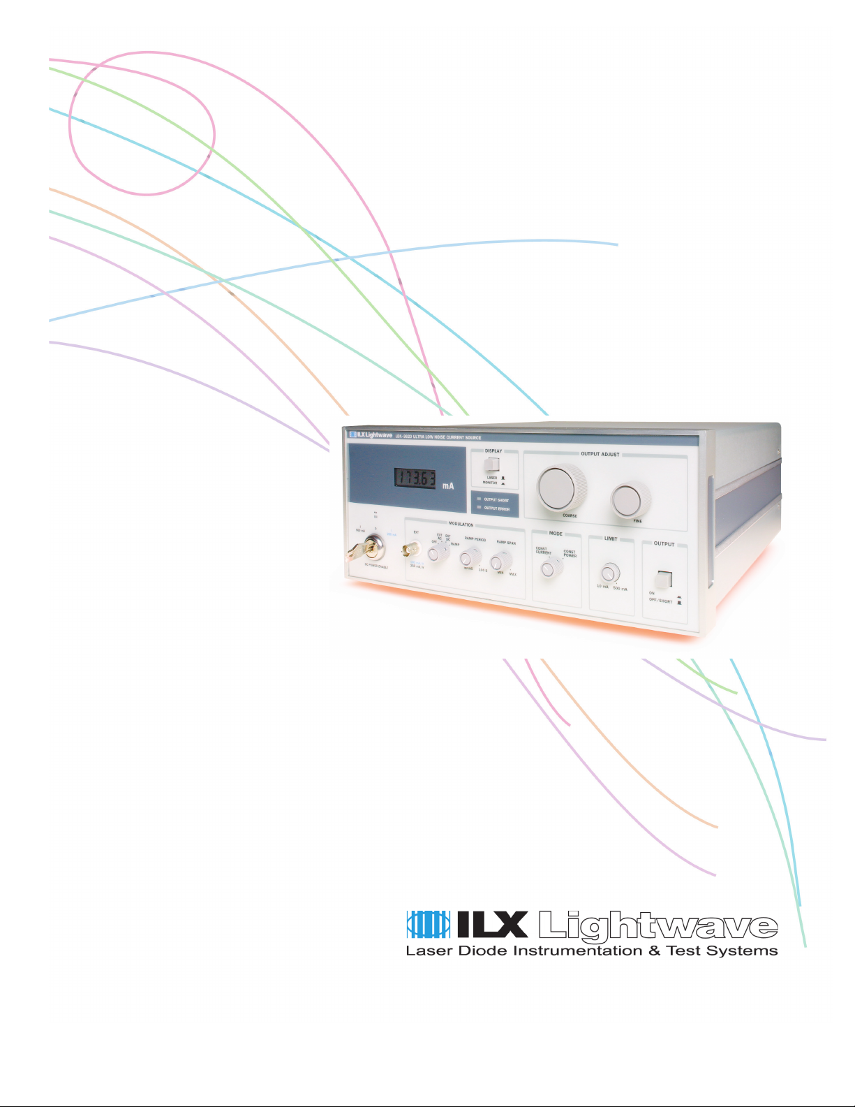
User’s Guide
Ultra Low Noise Current Source
LDX-3620
ILX Lightwave Corporation · P. O. Box 6310 · Bozeman, MT, U.S.A. 59771 · U.S. & Canada: 1-800-459-9459 · International Inquiries: 406-556-2481 · Fax 406-586-9405
ilx.custhelp.com · www.ilxlightwave.com
70001803 June 2008
Page 2

Page 3

TABLE OF CONTENTS
TABLE OF CONTENTS
Safety Information and the Manual . . . . . . . . . . . . . . . . . . . . . . . . . . . . . . . . . ix
General Safety Considerations . . . . . . . . . . . . . . . . . . . . . . . . . . . . . . . . . . . . ix
Safety Marking Symbols . . . . . . . . . . . . . . . . . . . . . . . . . . . . . . . . . . . . . . . . . x
Comments, Suggestions, and Problems . . . . . . . . . . . . . . . . . . . . . . . . . . . xiii
Chapter 1 Introduction and Specifications
Product Overview . . . . . . . . . . . . . . . . . . . . . . . . . . . . . . . . . . . . . . . . . . . . . . . . 1
Specifications . . . . . . . . . . . . . . . . . . . . . . . . . . . . . . . . . . . . . . . . . . . . . . . . . . . 2
Options and Accessories . . . . . . . . . . . . . . . . . . . . . . . . . . . . . . . . . . . . . . . . . . 4
362038 Long Life Battery Option . . . . . . . . . . . . . . . . . . . . . . . . . . . . . . . . . . 4
132 Rack Mount Kit . . . . . . . . . . . . . . . . . . . . . . . . . . . . . . . . . . . . . . . . . . . . 4
Chapter 2 Operation
Installation . . . . . . . . . . . . . . . . . . . . . . . . . . . . . . . . . . . . . . . . . . . . . . . . . . . . . . 5
AC Power/Battery Charge Considerations . . . . . . . . . . . . . . . . . . . . . . . . . . . 5
Tilt Foot Adjustment . . . . . . . . . . . . . . . . . . . . . . . . . . . . . . . . . . . . . . . . . . . . 5
Rack Mounting . . . . . . . . . . . . . . . . . . . . . . . . . . . . . . . . . . . . . . . . . . . . . . . . 5
Front Panel Control and Connectors . . . . . . . . . . . . . . . . . . . . . . . . . . . . . . . . 6
DC POWER Key Switch and Output Range Selection . . . . . . . . . . . . . . . . . . 6
Low Battery Indication and Shutdown . . . . . . . . . . . . . . . . . . . . . . . . . . . . . . 6
EXT Modulation . . . . . . . . . . . . . . . . . . . . . . . . . . . . . . . . . . . . . . . . . . . . . . . 6
RAMP Modulation . . . . . . . . . . . . . . . . . . . . . . . . . . . . . . . . . . . . . . . . . . . . . . 7
MODE Selector . . . . . . . . . . . . . . . . . . . . . . . . . . . . . . . . . . . . . . . . . . . . . . . . 7
06_08 LDX-3620 i
Page 4

TABLE OF CONTENTS
LIMIT Current Adjustment . . . . . . . . . . . . . . . . . . . . . . . . . . . . . . . . . . . . . . . . 7
OUTPUT On/Off . . . . . . . . . . . . . . . . . . . . . . . . . . . . . . . . . . . . . . . . . . . . . . . 7
OUTPUT ADJUST Controls . . . . . . . . . . . . . . . . . . . . . . . . . . . . . . . . . . . . . . 8
DISPLAY Selector . . . . . . . . . . . . . . . . . . . . . . . . . . . . . . . . . . . . . . . . . . . . . 8
Output 4-1/2 Digit LCD Display . . . . . . . . . . . . . . . . . . . . . . . . . . . . . . . . . . . . 8
OUTPUT SHORT Indicator . . . . . . . . . . . . . . . . . . . . . . . . . . . . . . . . . . . . . . . 9
OUTPUT ERROR Indicator . . . . . . . . . . . . . . . . . . . . . . . . . . . . . . . . . . . . . . 9
Rear Panel Controls and Connectors . . . . . . . . . . . . . . . . . . . . . . . . . . . . . . . 10
HIGH/LOW BANDWIDTH Selector . . . . . . . . . . . . . . . . . . . . . . . . . . . . . . . . 10
OUTPUT Connector (J401) . . . . . . . . . . . . . . . . . . . . . . . . . . . . . . . . . . . . . 10
PHOTODIODE Feedback Gain Adjustments . . . . . . . . . . . . . . . . . . . . . . . . 11
PHOTODIODE Feedback Input Jack . . . . . . . . . . . . . . . . . . . . . . . . . . . . . . 11
RAMP TRIGger Output Jack . . . . . . . . . . . . . . . . . . . . . . . . . . . . . . . . . . . . 11
CHASSIS GROUND Connector . . . . . . . . . . . . . . . . . . . . . . . . . . . . . . . . . . 11
AC POWER/Battery Charge Switch . . . . . . . . . . . . . . . . . . . . . . . . . . . . . . . 11
Fuse Holder . . . . . . . . . . . . . . . . . . . . . . . . . . . . . . . . . . . . . . . . . . . . . . . . . 12
LDX 3620 Operation Procedures . . . . . . . . . . . . . . . . . . . . . . . . . . . . . . . . . . . 13
Outline of Operation . . . . . . . . . . . . . . . . . . . . . . . . . . . . . . . . . . . . . . . . . . . 13
Load Considerations . . . . . . . . . . . . . . . . . . . . . . . . . . . . . . . . . . . . . . . . . . . 13
Safe Settings . . . . . . . . . . . . . . . . . . . . . . . . . . . . . . . . . . . . . . . . . . . . . . . . 14
Safety Interlock Connections . . . . . . . . . . . . . . . . . . . . . . . . . . . . . . . . . . . . 14
Laser Diode Connections and Shielding . . . . . . . . . . . . . . . . . . . . . . . . . . . . 14
Photodiode Feedback Connections . . . . . . . . . . . . . . . . . . . . . . . . . . . . . . . 15
RAMP TRIGger Output Connections . . . . . . . . . . . . . . . . . . . . . . . . . . . . . . 16
Setting the LIMIT Current . . . . . . . . . . . . . . . . . . . . . . . . . . . . . . . . . . . . . . . 19
Setting the Output in CONST CURRENT Mode . . . . . . . . . . . . . . . . . . . . . . 19
Setting the MODULATION Controls . . . . . . . . . . . . . . . . . . . . . . . . . . . . . . . 19
Using the Internal RAMP Generator . . . . . . . . . . . . . . . . . . . . . . . . . . . . . . . 20
Setting the Photodiode Feedback Gain . . . . . . . . . . . . . . . . . . . . . . . . . . . . 20
Setting the Laser Power in CONST POWER Mode . . . . . . . . . . . . . . . . . . . 21
ii LDX-3620
Page 5

Chapter 3 Maintenance
Battery Maintenance . . . . . . . . . . . . . . . . . . . . . . . . . . . . . . . . . . . . . . . . . . . . . 23
Battery Replacement . . . . . . . . . . . . . . . . . . . . . . . . . . . . . . . . . . . . . . . . . . . . . 24
Fuse Replacement . . . . . . . . . . . . . . . . . . . . . . . . . . . . . . . . . . . . . . . . . . . . . . . 24
Calibration . . . . . . . . . . . . . . . . . . . . . . . . . . . . . . . . . . . . . . . . . . . . . . . . . . . . . 25
Display Calibration . . . . . . . . . . . . . . . . . . . . . . . . . . . . . . . . . . . . . . . . . . . . 27
TABLE OF CONTENTS
MONITOR Current Display Calibration . . . . . . . . . . . . . . . . . . . . . . . . . . . . . 27
OUTPUT ADJUST Calibration . . . . . . . . . . . . . . . . . . . . . . . . . . . . . . . . . . . 28
LIMIT Current Calibration . . . . . . . . . . . . . . . . . . . . . . . . . . . . . . . . . . . . . . . 28
RAMP SPAN Calibration . . . . . . . . . . . . . . . . . . . . . . . . . . . . . . . . . . . . . . . 28
Disassembly . . . . . . . . . . . . . . . . . . . . . . . . . . . . . . . . . . . . . . . . . . . . . . . . . . . 29
06_08 LDX-3620 iii
Page 6

TABLE OF CONTENTS
iv LDX-3620
Page 7

LIST OF FIGURES
LIST OF FIGURES
Figure 2.1 LDX-3620 Front Panel . . . . . . . . . . . . . . . . . . . . . . . . . . . 10
Figure 2.2 LDX-3620 Rear Panel . . . . . . . . . . . . . . . . . . . . . . . . . . . 12
Figure 2.3 Output Connector Pin-Out . . . . . . . . . . . . . . . . . . . . . . . . 12
Figure 2.4 Common Laser Cathode - Photodiode Cathode
17
Figure 2.5 Common Laser Cathode - Photodiode Anode . . . . . . . . 17
Figure 2.6 Common Laser Anode - Photodiode Cathode
18
Figure 2.7 Common Laser Anode - Photodiode Anode . . . . . . . . . . 18
Figure 3.1 Front Panel Board Layout . . . . . . . . . . . . . . . . . . . . . . . . 25
Figure 3.2 Side Panel Board Layout . . . . . . . . . . . . . . . . . . . . . . . . . 26
Figure 3.3 Rear Panel Board Layout . . . . . . . . . . . . . . . . . . . . . . . . 26
06_08 LDX-3620 v
Page 8

LIST OF FIGURES
vi LDX-3620
Page 9

LIST OF TABLES
LIST OF TABLES
Table 2.1 OUTPUT ERROR Conditions . . . . . . . . . . . . . . . . . . . . . . .9
Table 2.2 LDX-3620 Recommended Safe Initial Settings . . . . . . . . . 14
Table 3.1 Estimated Battery Lifetime . . . . . . . . . . . . . . . . . . . . . . . . . 24
Table 3.2 Fuse Replacement . . . . . . . . . . . . . . . . . . . . . . . . . . . . . . . 24
06_08 LDX_3620 vii
Page 10

LIST OF TABLES
viii LDX_3620
Page 11
SAFETY AND WARRANTY INFORMATION
The Safety and Warranty Information section provides details about cautionary
symbols used in the manual, safety markings used on the instrument, and
information about the Warranty including Customer Service contact information.
Safety Information and the Manual
Throughout this manual, you will see the words Caution and Warning indicating
potentially dangerous or hazardous situations which, if not avoided, could result in
death, serious or minor injury, or damage to the product. Specifically:
Caution indicates a potentially hazardous situation which can result in minor or
moderate injury or damage to the product or equipment.
Warning indicates a potentially dangerous situation which can result in serious injury or
death.
WARNING
Visible and/or invisible laser radiation. Avoid direct exposure to the beam.
General Safety Considerations
If any of the following conditions exist, or are even suspected, do not use the
instrument until safe operation can be verified by trained service personnel:
• Visible damage
• Severe transport stress
• Prolonged storage under adverse conditions
• Failure to perform intended measurements or functions
If necessary, return the instrument to ILX Lightwave, or authorized local ILX
Lightwave distributor, for service or repair to ensure that safety features are
maintained (see the contact information on page xiii).
All instruments returned to ILX Lightwave are required to have a Return
Authorization Number assigned by an official representative of ILX Lightwave
Corporation. See Returning an Instrument on page xi for more information.
LDX-3620 ix
Page 12
SAFETY SYMBOLS
SAFETY SYMBOLS
This section describes the safety symbols and classifications.
Technical specifications including electrical ratings and weight are included within
the manual. See the Table of Contents to locate the specifications and other
product information. The following classifications are standard across all ILX
Lightwave products:
• Indoor use only
• Ordinary Protection: This product is NOT protected against the harmful ingress of moisture.
• Class I Equipment (grounded type)
• Mains supply voltage fluctuations are not to exceed ±10% of the nominal supply voltage.
• Pollution Degree II
• Installation (overvoltage) Category II for transient overvoltages
• Maximum Relative Humidity: <80% RH, non-condensing
• Operating temperature range of 0 °C to 40 °C
• Storage and transportation temperature of –40 °C to 70 °C
• Maximum altitude: 3000 m (9843 ft.)
• This equipment is suitable for continuous operation.
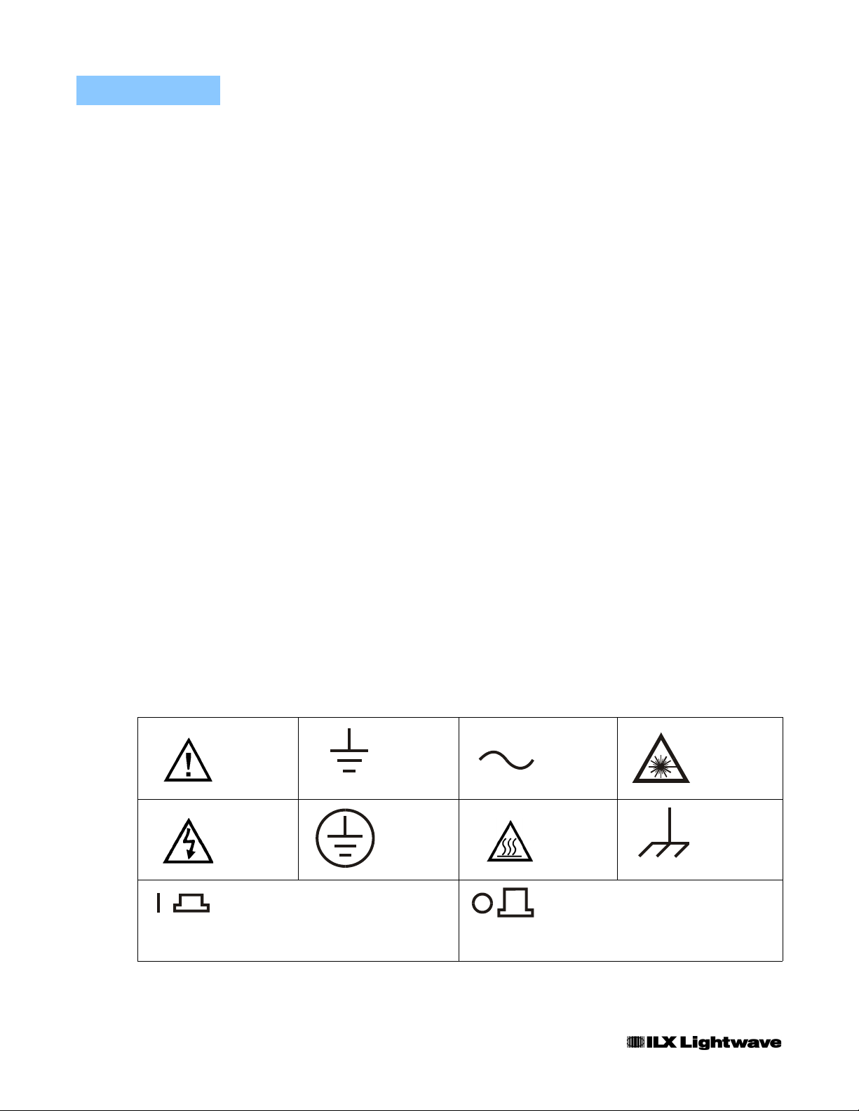
Safety Marking Symbols
This section provides a description of the safety marking symbols that appear on
the instrument. These symbols provide information about potentially dangerous
situations which can result in death, injury, or damage to the instrument and other
components.
Caution,
refer to
manual
Caution, risk
of electric
shock
On: In position of a bistable push control.
The slash (I) only denotes that mains are on.
or
(I)
Earth
ground
Te r mi n a l
Protective
Conductor
Te r mi n a l
Alternating
current
Caution, hot
surface
Off: Out position of a bistable push control.
The circle (O) only denotes that mains are off.
or
(O)
Visible and/or
invisible laser
radiation
Frame or
chassis
Te r mi n a l
x LDX-3620
Page 13

WARRANTY
ILX LIGHTWAVE CORPORATION warrants this instrument to be free from
defects in material and workmanship for a period of one year from date of
shipment. During the warranty period, ILX will repair or replace the unit, at our
option, without charge.
Limitations
This warranty does not apply to fuses, lamps, defects caused by abuse,
modifications, or to use of the product for which it was not intended.
This warranty is in lieu of all other warranties, expressed or implied, including any
implied warranty of merchantability or fitness for any particular purpose. ILX
Lightwave Corporation shall not be liable for any incidental, special, or
consequential damages.
WAR RA NT Y
If a problem occurs, please contact ILX Lightwave Corporation with the
instrument's serial number, and thoroughly describe the nature of the problem.
Returning an Instrument
If an instrument is to be shipped to ILX Lightwave for repair or service, be sure to:
1 Obtain a Return Authorization number (RA) from ILX Customer Service.
2 Attach a tag to the instrument identifying the owner and indicating the required service or
repair. Include the instrument serial number from the rear panel of the instrument.
3 Attach the anti-static protective caps that were shipped with the instrument and place the
instrument in a protective anti-static bag.
4 Place the instrument in the original packing container with at least 3 inches (7.5 cm) of
compressible packaging material. Shipping damage is not covered by this warranty.
5 Secure the packing box with fiber reinforced strapping tape or metal bands.
6 Send the instrument, transportation pre-paid, to ILX Lightwave. Clearly write the return
authorization number on the outside of the box and on the shipping paperwork. ILX
Lightwave recommends you insure the shipment.
If the original shipping container is not available, place your instrument in a
container with at least 3 inches (7.5 cm) of compressible packaging material on all
sides.
Repairs are made and the instrument returned transportation pre-paid. Repairs
are warranted for the remainder of the original warranty or for 90 days, whichever
is greater.
06_08 LDX-3620 xi
Page 14

WAR RA NT Y
Claims for Shipping Damage
When you receive the instrument, inspect it immediately for any damage or
shortages on the packing list. If the instrument is damaged, file a claim with the
carrier. The factory will supply you with a quotation for estimated costs of repair.
You must negotiate and settle with the carrier for the amount of damage.
xii LDX-3620
Page 15

WAR RA NT Y
Comments, Suggestions, and Problems
To ensure that you get the most out of your ILX Lightwave product, we ask that
you direct any product operation or service related questions or comments to ILX
Lightwave Customer Support. You may contact us in whatever way is most
convenient:
Phone . . . . . . . . . . . . . . . . . . . . . . . . . . . (800) 459-9459 or (406) 586-1244
Fax . . . . . . . . . . . . . . . . . . . . . . . . . . . . . . . . . . . . . . . . . . . . . (406) 586-9405
On the web at: . . . . . . . . . . . . . . . . . . . . . . . . . . . . . . . . . . . . ilx.custhelp.com
Or mail to:
ILX Lightwave Corporation
P. O. Box 6310
Bozeman, Montana, U.S.A 59771
www.ilxlightwave.com
When you contact us, please have the following information:
Model Number:
Serial Number:
End-user Name:
Company:
Phone:
Fax:
Description of what is
connected to the ILX
Lightwave instrument:
Description of the problem:
If ILX Lightwave determines that a return to the factory is necessary, you are
issued a Return Authorization (RA) number. Please mark this number on the
outside of the shipping box.
You or your shipping service are responsible for any shipping damage when
returning the instrument to ILX Lightwave; ILX recommends you insure the
shipment. If the original shipping container is not available, place your instrument
06_08 LDX-3620 xiii
Page 16

WAR RA NT Y
in a container with at least 3 inches (7.5 cm) of compressible packaging material
on all sides.
We look forward to serving you even better in the future!
xiv LDX-3620
Page 17

CHAPTER 1
INTRODUCTION AND SPECIFICATIONS
This manual contains operation and maintenance information for the LDX-3620
Ultra Low Noise Current Source and its options. Chapter 2 contains control and
connector descriptions and operation procedures. Chapter 3 contains battery and
maintenance information.
Note: To those in a hurry to turn on and use the LDX-3620 without reading Chapter 2 of
this manual, it is recommended that the IMPORTANT paragraphs be read since they
contain informaiton that may prevent the destruction of expenvie laser diodes. Output
connector pin-outs are found in Figure 2.3. Recommended cable shielding schemes are
found in Figures 2.4 - 2.8. Figure 3.1 is a block diagram of the LDX-3620.
Product Overview
The LDX-3620 Ultra Low Noise Current Source provides laser diode users a
power source for applications requiring current stabilities of better than 10 ppm
and noise levels lower than 2 uA in the 5 Hz to 10 MHz band. Its features include:
• Low noise, battery based design
• Built-in battery charger
• High output stability
• Current limit protection
• Two output current ranges: 200 mA and 500 mA
• 4-1/2 digit resolution and display
• Monitor photodiode current display
• Photodiode feedback input for constant optical power operation
• Internal ramp generator with trigger output
• External modulation capability
• Low battery shutdown protection
• High/Low bandwidth switch
LDX-3620 1
Page 18
CHAPTER 1
INTRODUCTION AND SPECIFICATIONS
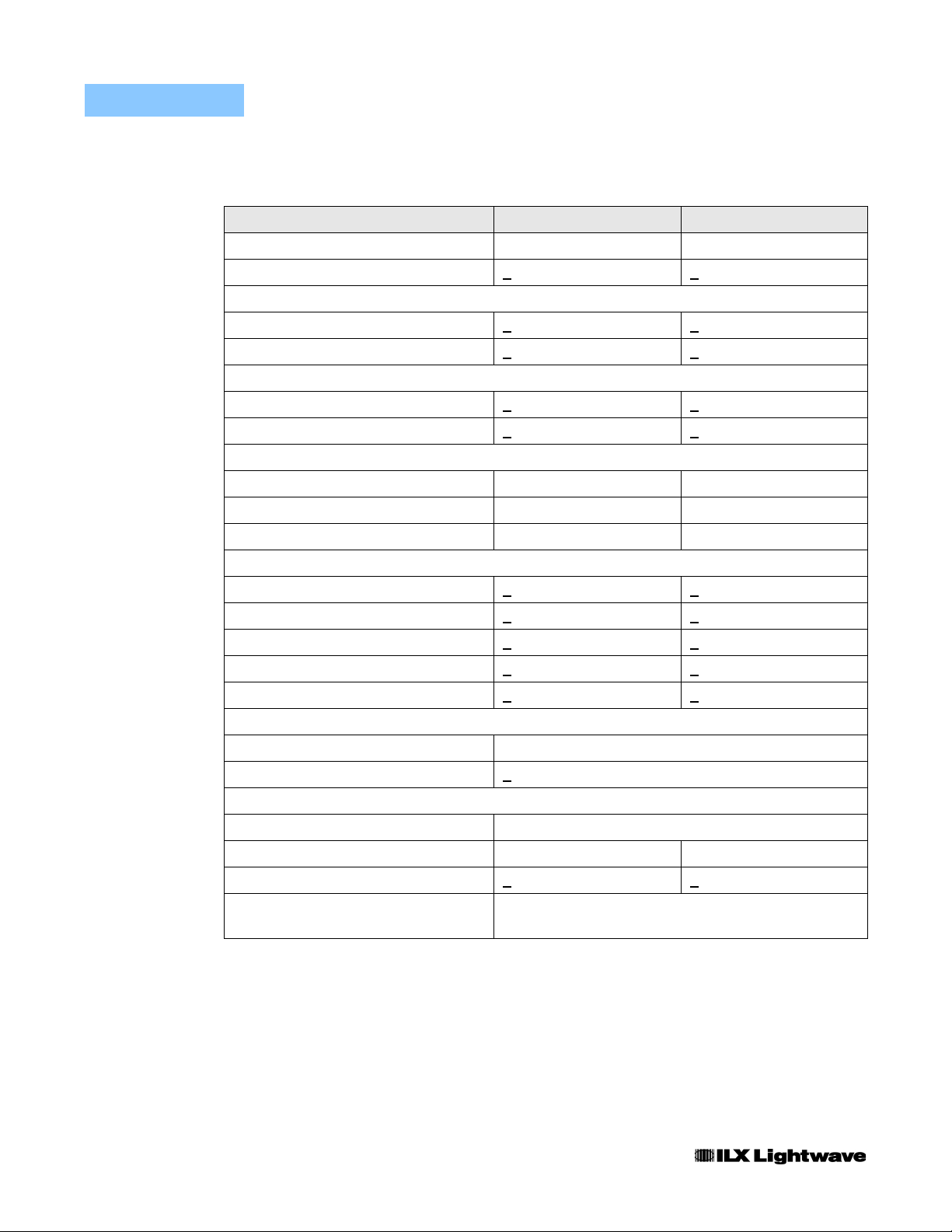
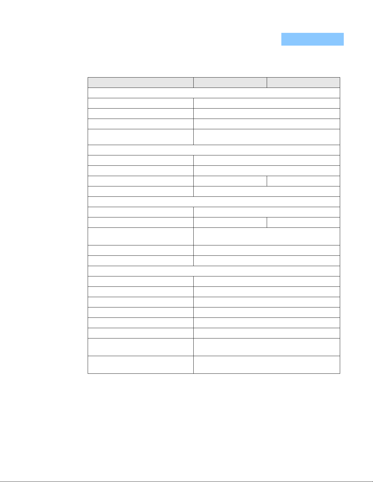
Specifications
Specifications
Output Current 0 - 200 mA 0 - 500 mA
Compliance Voltage >5 V >4 V
Noise and Ripple (5 Hz - 10 MHz bandwidth)
Battery Operation
AC Line Operation
Noise and Ripple (5 Hz - 10 kHz bandwidth)
Battery Operation
AC Line Operation
Noise Density (Battery Operation)
50/60 Hz
1 kHz
25 kHz
0 - 200 mA Range 0 - 500 mA Range
850 nA rms <2 uA rms
<
3 uA rms <8 uA rms
<
100 nA rms <500 nA rms
<
2 uA rms <6.5 uA rms
<
5.2 nA/rt Hz 11.5 nA/rt Hz
815 pA/rt Hz 2.6 nA/rt Hz
315 pA/rt Hz 795 pA/rt Hz
Stability
10 - 20 seconds
3 - 5 minutes
10 - 30 minutes
Temperature Coefficient <
Transients <
CURRENT LIMIT
Range 10 - 500 mA
Accuracy +
DISPLAY
Type 4-1/2 digit LCD
Resolution 0.01 mA 0.1 mA
Accuracy +0.05 mA +0.6 mA
Reads Units LASER diode current in mA
0.1 ppm <0.1 ppm
<
1 ppm <1 ppm
<
10 ppm <10 ppm
<
10 ppm/oC<10 ppm/oC
10 uA <10 uA
5 mA
MONITOR photodiode current in mA
2 LDX-3620
Page 19
INTRODUCTION AND SPECIFICATIONS
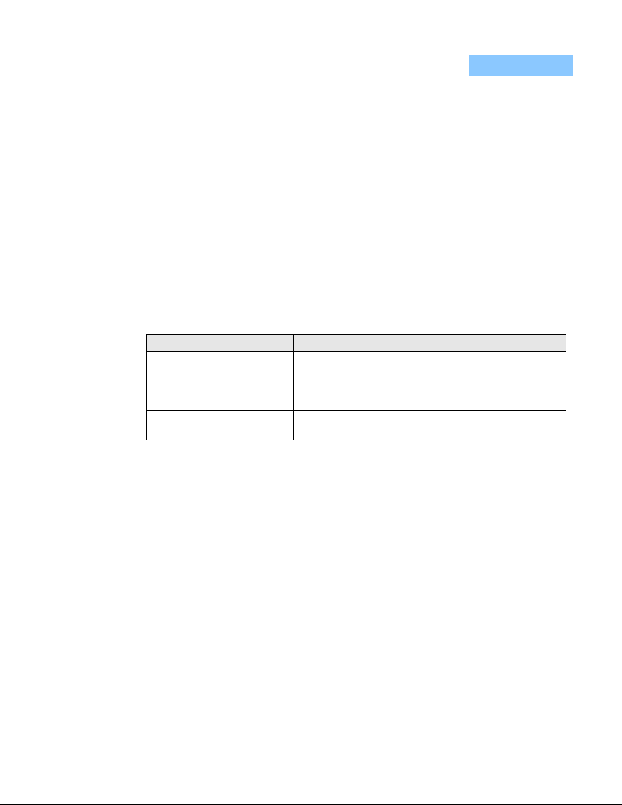
Specifications
0 - 200 mA Range 0 - 500 mA Range
MODULATION / FEEDBACK INPUTS
Photodiode Feedback
Input Type
Range
Connectors
External Modulation Input (Bandwidth (3 dB point)
AC Coupled
DC Coupled
Transfer Function 100 mA/V 250 mA/V
Connector Isolated front panel BNC jack
Internal Ramp Generator
Period
Span Adjustment
Ramp Trigger
Ramp Flyback Time
Output Connector
GENERAL
Current input from external photodiode
20 uA to 2 mA for full scale output
Rear panel isolated BNC jack or 9-pin rear panel
D-sub connector
100 Hz to 1 MHz
0 Hz to 1 MHz
Adjustable 50 msec to 100 sec
0 - 200 mA 0 - 500 mA
Ramp start trigger for oscilloscope output
Optically isolated open collector TTL output
700 usec, approximately
Shielded 9-pin D-sub on rear panel
CHAPTER 1
AC Power Input Voltage Range 100 - 125 or 210 - 250 VAC
AC Power Line Frequency 50/60 Hz
Battery +12 V Supply 4.5 amp-hour sealed lead-acid battery (standard)
Battery -12 V Supply 1.2 amp-hour sealed lead-acid battery
o
Operating Temperature Range 0 to 40
Storage Temperature Range -40 to 70
Weight 8.6 kg (18.9 lbs)
12 kg (26.4 lbs) with extra battery option
Size (H x W x D) 145 mm x 320 mm x 346 mm
5 5/8” x 12 1/2” x 13 5/8”
C
o
C
Our goal is to make the best laser diode instrumentation available anywhere. To
achieve this, we need your ideas and comments on ways we can improve out
products. We invite you to contact us at any time with your suggestions.
06_08 LDX-3620 3
Page 20

CHAPTER 1
INTRODUCTION AND SPECIFICATIONS
Options and Accessories
Options and Accessories
362038 Long Life Battery Option
The 362038 option is a second, user installable +12 volt battery which doubles the
battery operation time at 500 mA. Instructions for battery installation are included
with the 362038 option kit.
132 Rack Mount Kit
The 132 rack mount kit enables installation of the 3620 into a standard 19 inch
wide rack. All hardware and instructions are included with the kit.
4 LDX-3620
Page 21

CHAPTER 2
OPERATION
This chapter contains the following aspects of operation of the LDX-3620:
• General power and installation considerations
• A description of the front and rear panel controls and connectors
• Step-by-step instructions on the set-up and the use of the LDX-3620
Installation
AC Power/Battery Charge Considerations
The LDX-3620 is normally configured at the factory for your power line voltage.
The unit can be configured for 100-130 VAC or 210-230 VAC operation. Check to
be sure that the correct range is marked on the rear panel. If it is not correct, see
Chapter 3 for the procedure to change the line voltage range.
The AC power cord connects to the rear of the unit. Turning on the AC POWER
switch on the rear panel charges the batteries while permitting full use of the
LDX-3620’s functions; however, noise will be increased in this configuration.
Tilt Foot Adjustment
The LDX-3620 can be tilted for easier viewing using the extensions on the front
feet of the unit. These extenders can be rotated 90 degrees until they lock into
position. To put the extenders flat against the bottom of the unit, firmly press them
back.
Rack Mounting
The instructions and necessary hardware for mounting the LDX-3620 in a
standard 19 inch wide instrument rack are available in the Model 132 Rack
Mounting Kit. Contact ILX Lightwave for more information.
LDX-3620 5
Page 22

CHAPTER 2
OPERATION
Front Panel Control and Connectors
Front Panel Control and Connectors
A brief description of the function of the front panel controls and connectors is
contained in the following sections.
DC POWER Key Switch and Output Range Selection
A three position key switch on the front panel of the LDX-3620 controls the power
to the current source circuits:
• Off - center position
• 200 mA - 1/8 turn clockwise (CW)
• 500 mA - 1/8 turn counter-clockwise (CCW)
The front panel power key switch operates independently of the rear panel AC
POWER switch. The rear panel switch controls only AC-line-power/battery-charge
operation. With the rear panel switch turned on, the power LED above the front
panel key switch will light up, indicating that AC power is on and that the batteries
are charging.
Low Battery Indication and Shutdown
A “B” indicated on the display of the LDX-3620 means that the batteries should be
recharged. Repeated operation of the unit to the point where the low battery “B” is
indicated greatly reduces the battery life and is not recommended. See Chapter 3
for recommended battery maintenance.
If the batteries continue to be discharged after the low battery “B” indicator
appears, shutdown circuits may turn off the output of the LDX-3620. Shutdown is
indicated on the display when all of the decimal points are displayed. Use of the
instrument will be diabled until the batteries have been recharged and the DC
POWER key switch has been turned off and then on again.
EXT Modulation
An external voltage wave form can be used to modulate the LDX-3620 output
when the modulation mode selection switch is set to either the EXT AC or EXT DC
positions. The external signal is input through the front panel EXT BNC jack and is
AC or DC coupled according to the mode switch positions. The transconductance
of the instrument is determined by the output current range selected by the DC
POWER key switch; it is 100 mA/V in the 200 mA output range, or 250 mA/V in
the 500 mA output range. Under all modes of operation, the output is clipped at
the level set by the current LIMIT knob.
6 LDX-3620
Page 23

OPERATION
Front Panel Control and Connectors
CHAPTER 2
RAMP Modulation
The LDX-3620 output can be modulated using the internal ramp generator when
the MODULATION selector switch is set to the RAMP position. The ramp period is
variable between 50 mSec and 100 Sec via the RAMP PERIOD adjustment pot.
The ramp peak-to-peak amplitude is adjusted using the RAMP SPAN front panel
pot. A DC offset may be added to the ramp by using the OUTPUT ADJUST knobs.
Ramp fly-back time is approximately 700 microseconds. The ramp wave form will
be clipped, should it try to exceed the current limit.
MODE Selector
The front panel MODE switch selects the feedback mode of the LDX-3620. In
CONST CURRENT mode, the LDX-3620 is a voltage controlled current source
that delivers a current proportional to the sum of the MODULATION section and
OUTPUT ADJUST knob control signals.
In the CONST POWER mode, the LDX-3620 uses the photodiode feedback
signal to determine how much current should be output to the laser or LED to
maintain a constant light power. The output current increases until the photodiode
feedback current equals a value proportional to the control signal set by the
MODULATION and the OUTPUT ADJUST sections on the front panel. If the
control signal is a DC level, then the output optical power is held constant. If the
control signal is modulated, then the output optical power is modulated, so long as
the bandwidth of the modulation is held below 20 Hz. Modulation frequency
components higher than 20 Hz are attenuated, and the modulation becomes a
mixture of optical power modulation and current modulation.
LIMIT Current Adjustment
The LIMIT knob on the front panel sets the output current limit level. Setting this
knob fully clockwise (CW) limits the LDX-3620 output current to 500 mA. Setting it
fully counter-clockwise (CCW) limits the output to approximately 10 mA. The
current limit is active in all operating modes of the LDX-3620. A more complete
description of how to set current limit may be found later in this chapter.
OUTPUT On/Off
The current output of the LDX-3620 is shorted by a mechanical switch and a JFET
when the front panel OUTPUT push button switch is in the OFF/SHORT position
(out). When the OUTPUT switch is set to the ON position, the short is removed
and the JFET is turned off slowly. This brings the output current up slowly to the
level determined by the OUTPUT ADJUST and MODULATION control signals.
06_08 LDX-3620 7
Page 24

CHAPTER 2
OUTPUT ADJUST Controls
DISPLAY Selector
OPERATION
Front Panel Control and Connectors
When the output is shorted internally, the OUTPUT SHORT LED on the front
panel will light up.
The OUTPUT ADJUST, COARSE, and FINE knobs set the DC output level of the
LDX-3620. The DC bias level is summed with the control signals derived from the
MODULATION section to determine the final output level.
The display of the LDX-3620 indicates the average output current of the unit when
the DISPLAY push button switch is in the LASER position (out). It displays the
average photodiode feedback current input to the rear panel when the DISPLAY
switch is in the MONITOR position (in).
Note: When in the MONITOR position (in), the display reads the negative value of the
average photodiode current. This reminds the user that the display switch is in the
MONITOR position.
Output 4-1/2 Digit LCD Display
The LDX-3620 output current and monitor photodiode current are displayed on a
4-1/2 digit liquid crystal display on the front panel of the instrument. When the
DISPLAY push button is in the LASER position (out), the display reads the
average current setting determined by the MODULATION and OUTPUT ADJUST
controls. It does so even when the OUTPUT push button is in the OFF/SHORT
position (out) and no current is delivered to the output. The resolution of the
display depends on the range selected by the DC POWER key switch: 0.01 mA in
the 200 mA setting and 0.1 mA in the 500 mA setting.
When the DISPLAY switch is in the MONITOR position (in), the display reads the
(negative) average photodiode current input to the rear panel photodiode
feedback inputs in milliamperes. This reading is negative to remind the user that
the display is in the MONITOR position. The resolution of the display in MONITOR
mode does not change with the output range selected by the DC POWER key
switch.
The display also announces low battery charge by indicating a "B".
If "low battery shutdown" occurs, the display reads zero current and all of the
decimals are displayed.
8 LDX-3620
Page 25
OPERATION
Front Panel Control and Connectors
CHAPTER 2
OUTPUT SHORT Indicator
The green OUTPUT SHORT lamp lights up when the output is shorted by setting
the OUTPUT on/off switch to the OFF/SHORT position (out). It is unlit when the
OUTPUT is ON.
OUTPUT ERROR Indicator
The red OUTPUT ERROR indicator lights up when:
• The output has reached the current LIMIT level, set by the LIMIT adjustment.
• The output circuit is open.
• The maximum compliance voltage of the LDX 3620 is insufficient to drive the load.
Table 2.1 lists the possible conditions leading to a lighted OUTPUT ERROR LED.
Table 2.1 OUTPUT ERROR Conditions
Condition Indicated By
Current Limit OUTPUT ERROR LED is lit
Display reads value of LIMIT current
Open Circuit OUTPUT ERROR LED is lit
Display reads zero
Compliance Voltage Exceeded OUTPUT ERROR LED is lit
Display reads a non-zero value less than the LIMIT current
06_08 LDX-3620 9
Page 26
CHAPTER 2
OPERATION
Rear Panel Controls and Connectors
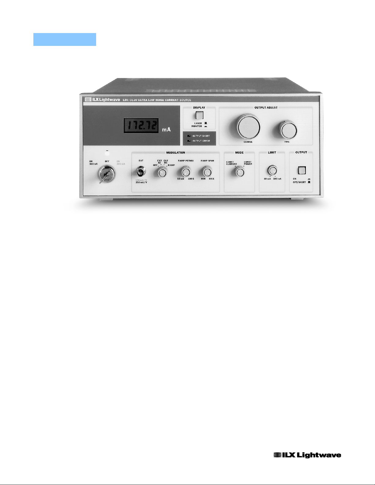
Figure 2.1 LDX-3620 Front Panel
Rear Panel Controls and Connectors
The following sections contain brief descriptions of the functions of the rear panel
controls and connectors. Refer to Figure 2.2.
HIGH/LOW BANDWIDTH Selector
The BANDWIDTH selector switches a 0.1 uF capacitor in and out of the output
circuit. This capacitor is connected directly across the output current posts. The
capacitor is connected when the LOW bandwidth position is selected, and it is
disconnected when the HIGH bandwidth position is selected.
In the HIGH position the modulated output bandwidth of the LDX-3620 is 1 MHz.
With the switch in the LOW position the bandwidth across a 100 ohm load is cut to
about 20 kHz. The LOW setting decreases noise and prevents oscillation of the
LDX-3620 when it is connected to an inductive load, such as a bias "tee" circuit.
This allows external modulation of the laser diode using the LDX-3620 as a bias
current supply.
10 LDX-3620
OUTPUT Connector (J401)
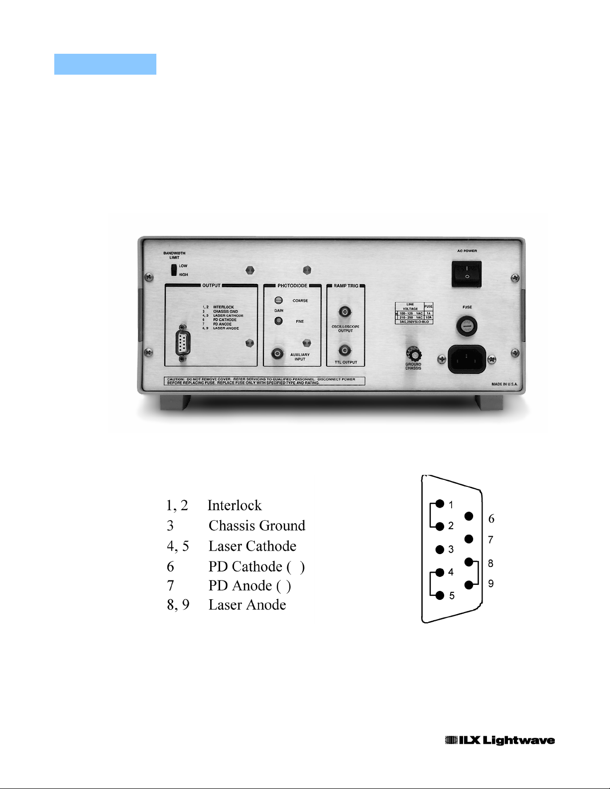
The rear panel 9-pin D-sub connector (J401) pin-outs are shown in Figure 2.3.
The LDX-3620 output current is sourced (+) from pins 8 and 9 and the current
Page 27

OPERATION
Rear Panel Controls and Connectors
returned (-) to pins 4 and 5. The monitor photodiode feedback current is input to
pin 7 (+) and returned from pin 6 (-). The feedback leads should be shielded with
an earth-ground shield available on pin 3. More detailed information on
connections and grounding is included later in this chapter.
Pins 1 and 2 of the rear panel OUTPUT can be connected to an external safety
interlock switch to disable the LDX-3620 current output when the switch is
opened. Instructions on the connection of an interlock switch are located later in
this chapter.
CHAPTER 2
PHOTODIODE Feedback Gain Adjustments
The photodiode feedback circuit gain is adjustable on the rear panel to accept fullscale feedback currents from 20 uA to 2 mA. An eight position switch provides
COARSE gain adjustment, while a four-turn trimpot provides FINE adjustment.
The adjustment procedure is described later in this chapter.
PHOTODIODE Feedback Input Jack
The photodiode feedback current may optionally be input through a rear panel
BNC jack. This jack is connected in parallel with pins 6 and 7 of the rear panel 9
pin D subminiature connector.
RAMP TRIGger Output Jack
Optically isolated RAMP TRIGGER signals are output through two BNC jacks on
the rear panel. The OSCILLOSCOPE output delivers a 200 mV square pulse with
rising and falling edges of the pulse synchronized to the end and start of the
output current ramp. This output remains high during the ramp flyback time of
approximately 700 microseconds.
The OPEN COLLECTOR output is capable of driving a TTL load, but requires an
external supply and pull-up resistor. See the section on Ramp Trigger Output
Connectors for connection information.
CHASSIS GROUND Connector
Chassis ground is available on the rear of the unit through a banana jack
connected to the LDX-3620 cabinet. When a three-wire line cord with earthground is used, the cabinet of the LDX-3620 is connected to the ground lead of
the power cord.
AC POWER/Battery Charge Switch
AC line power operation and battery recharge is accomplished by connecting the
AC line cord and turning on the AC Power switch on the rear panel. With this
06_08 LDX-3620 11
Page 28
CHAPTER 2
Fuse Holder
OPERATION
Rear Panel Controls and Connectors
switch turned off, the LDX-3620 draws power from its internal battery supply. For
lowest noise operation, the AC POWER switch should be OFF and the AC power
cord disconnected.
The AC line fuse holder is on the rear panel. See Chapter 3 for fuse replacement
information.
Figure 2.2 LDX-3620 Rear Panel
-
+
Figure 2.3 Output Connector Pin-Out
12 LDX-3620
Page 29

OPERATION
LDX 3620 Operation Procedures
LDX 3620 Operation Procedures
Chapter 3 contains information concerning the battery operation of the LDX-3620.
(Briefly: it recommends that the batteries be maintained as fully charged as
possible to ensure long battery life.)
This section contains recommended procedures for operation of the LDX-3620
with a laser diode. It assumes that the batteries are adequately charged or that
AC power is connected and on.
CHAPTER 2
Outline of Operation
Operation of the LDX-3620 can be outlined briefly:
1 Set controls to a safe configuration (see Table 2.2) before connecting the laser and
turning on the DC POWER key switch.
2 Connect the laser using one of the recommended shielding schemes (Figure 2.4). Be
sure connections are secure and not prone to open should the cables be jostled or
bumped. Refer to later in this chapter for photodiode feedback connections.
3 Leave the OUTPUT switch in the OFF/SHORT position (out). Turn on the DC power to the
appropriate range and adjust the current LIMIT to a safe level for the particular laser being
used.
4 In CONST CURRENT mode, adjust the output current to the desired level with the
OUTPUT ADJUST and/or MODULATION controls and turn ON the OUTPUT (in).
5 In CONST POWER mode, adjust the photodiode feedback gain to get maximum
resolution on the OUTPUT ADJUST knobs. Then set the output power level with the
OUTPUT ADJUST knobs.
6 Before turning off the DC POWER key switch, set the OUTPUT switch to the OFF/SHORT
position (out).
7 Recharge the batteries by connecting the LDX-3620 to the AC line, and turn on the rear
panel AC POWER switch.
The procedures for each of these steps are contained in the following sections.
Load Considerations
The LDX-3620 is intended as a current source for laser diode and LED loads.
When it is used with a resistive load, the resistance value of the limiting resistor
should be selected so that the compliance voltage is not exceeded. For example,
a laser diode which has a voltage drop of 1.8 volts may be connected in series
with a limiting resistor. If the 200 mA range is selected on the LDX-3620, the
guaranteed compliance voltage is +5 volts. If the current LIMIT is set to 100 mA,
the maximum resistance value can be found by Ohm's Law:
(R = E / I) 3.2 V / 0.1 A = 32 ohms
06_08 LDX-3620 13
Page 30
CHAPTER 2
Safe Settings
OPERATION
LDX 3620 Operation Procedures
Note: If the LDX-3620 is to be connected to an inductive load, such as a bias "tee"
network, the LOW BANDWIDTH setting (on the rear panel) should be used. This is
necessary to prevent oscillation of the LDX-3620.
Before turning the DC power on, the front panel controls should be set to a safe
configuration. Table 2.2 lists the recommended settings.
Table 2.2 LDX-3620 Recommended Safe Initial Settings
Front Panel Control Recommended Setting
OUTPUT switch OFF/SHORT (out)
MODE knob CONST CURRENT
MODULATION knob OFF
DISPLAY switch LASER (out)
OUTPUT ADJUST knobs Fully counter-clockwise (CCW)
LIMIT knob Fully counter-clockwise (CCW)
Safety Interlock Connections
A safety interlock connection is available on pins 1 and 2 of the LDX-3620 rear
panel OUTPUT connector. These pins must be shorted to enable the LDX-3620
current output. When this circuit is opened, the interlock turns off the current
output, and the OUTPUT SHORT indicator lights up. Then when the circuit is reclosed, the output turns on slowly in the same manner as when the front panel
OUTPUT push button switch is turned ON (in).
To use the interlock feature, the user must provide wires connected from the
OUTPUT connector interlock pins to a normally closed, external, user supplied
switch or relay. These connections must be electrically isolated from all other
circuits.
The interlock pins are shorted together inside the hood of the mating male, 9 pin
D-sub output connector supplied with the LDX-3620.
Laser Diode Connections and Shielding
Note: Before connecting the laser diode to the LDX-3620, be sure that the front panel
OUTPUT switch is in the OFF/SHORT position (out). Before turning the OUTPUT on, be
sure that the current LIMIT has been correctly set.
The LDX-3620 output is available through the 9-pin rear panel OUTPUT
connector J401 (see Figure 2.3). The LDX-3620 sources current through pins 8
and 9 to the laser anode (+) and returns current from the cathode (-) through pins
4 and 5.
14 LDX-3620
Page 31

OPERATION
LDX 3620 Operation Procedures
Note: The cable connections to the laser must be secure enough that they won't open
circuit, should they be jostled or bumped. Should an open circuit occur during laser
operation, DO NOT attempt to remake the circuit until the front panel OUTPUT switch has
been released to the OFF/SHORT position (out). Remaking the circuit with the OUTPUT on
will expose the laser to the maximum compliance voltage of the LDX-3620, which may
result in laser damage.
A laser may be damaged if an open circuit occurs during laser operation while the output is
on. The damage is caused by a momentary circuit break and remake, before the final
circuit break. Therefore, always make sure that the cabling is secure. An open circuit is
indicated by the front panel OUTPUT ERROR lamp and a zero current reading on the
display.
If the LDX-3620 is to be used in CONST POWER mode, the photodiode feedback
current should be sourced to pin 7 (+) and returned from pin 6 (-) of the rear panel
9-pin connector. Alternatively, the feedback current can be connected through the
rear panel AUX. INPUT BNC connector, using the center conductor of the coax for
the "+" connection, and the outer shield conductor for the " - " connection.
It is recommended that the connections to the LDX-3620 output be made by using
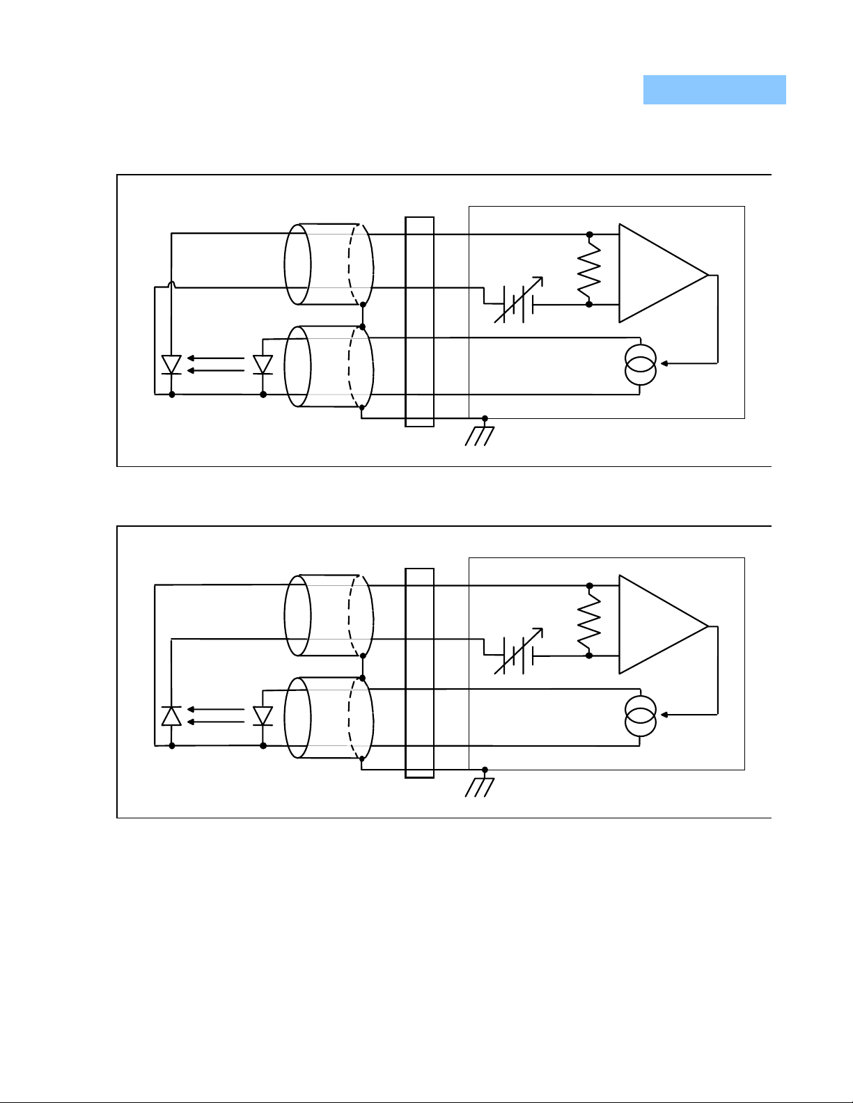
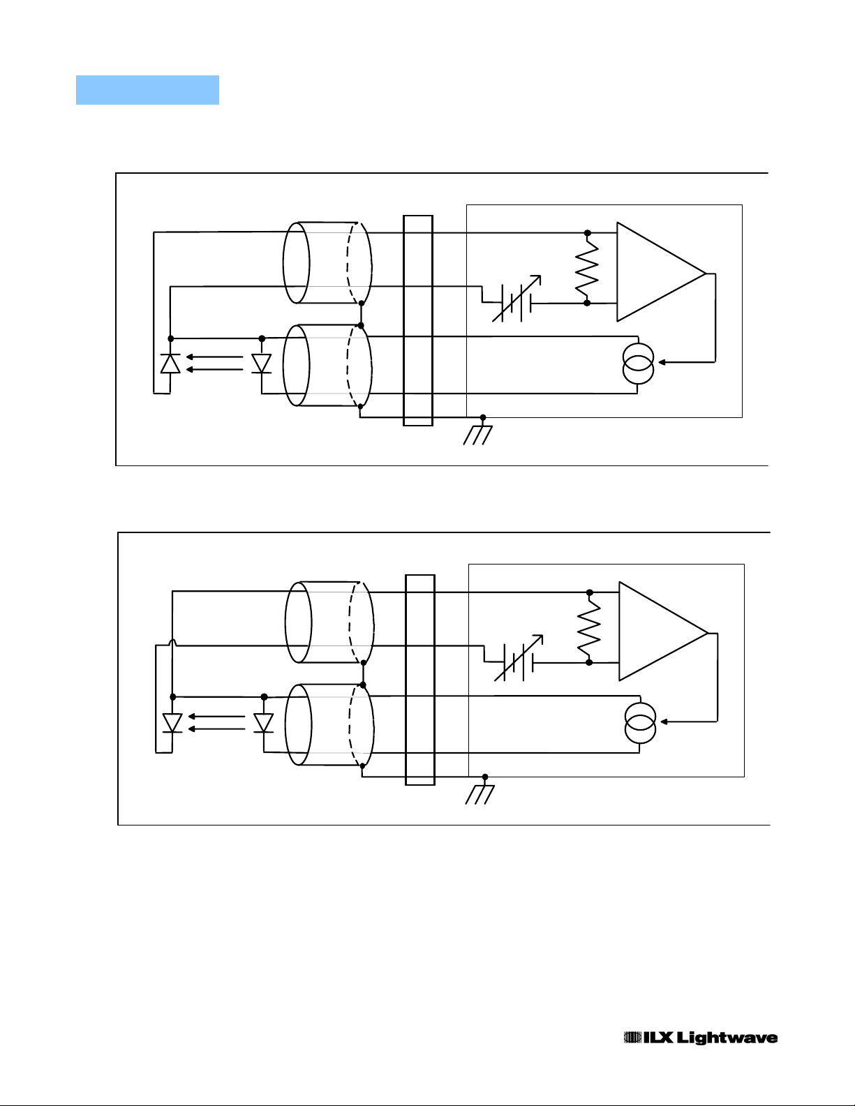
twisted wire pairs, with an earth grounded shield, as shown in Figures 2.4 - 2.7.
The output conductors are left floating, relative to earth-ground, to suppress AC
power-on/power-off transients that may occur through an earth-ground return
path. If the output circuit is earth-grounded at some point (such as through the
laser package and mount), then the user must be careful to avoid multiple earthgrounds in the circuit. Multiple earth-grounds may provide circuit paths that induce
spurious currents in the photodiode feedback circuit and output leads.
CHAPTER 2
Photodiode Feedback Connections
Many laser diode modules contain an internal photodiode that monitors the backfacet emission of the laser. This photodiode is usually internally connected to
either the laser anode or cathode. Figures 2.4 - 2.7 show the recommended
connections and shielding for the various configurations of laser diode modules
and photodiode feedback schemes.
The feedback photodiode reverse-biasing supply shown in these figures must be
supplied by the user. It is located in the circuit where it will not cause the common
mode voltage of the feedback inputs to exceed their specified maximum of +6
volts, relative to the "-" current output terminal (pins 4 and 5 of J401). Noise from
this biasing supply may contribute to the output noise levels; therefore, a battery
with shielded connections is recommended.
If a feedback photodiode is used, which is electrically isolated from the laser, the
feedback circuit must be resistively "tied" at some point to the output circuit. A
large resistance of 1 MΩ, connected from the laser cathode to the photodiode
anode, may be used in place of the direct connection (see Figure 2.5). This is
done to keep the feedback inputs within the specified maximum +6 volt common
06_08 LDX-3620 15
Page 32

CHAPTER 2
RAMP TRIGger Output Connections
OPERATION
LDX 3620 Operation Procedures
mode voltage, relative to the " - " laser current output (pins 4 and 5 of J401). The
circuit of Figure 2.5 should be used, if feasible.
Two optically isolated RAMP TRIGGER outputs are provided on the LDX-3620
rear panel. The OSCILLOSCOPE output provides a voltage square pulse of up to
200 mV amplitude that is synchronized to the start and end of the output current
ramp. The falling edge of the voltage pulse signals the start of the output current
ramp. The rising edge signals the end of the ramp. This output remains high
during the approximately 700 microsecond ramp flyback. The OSCILLOSCOPE
output should be connected to an instrument with an input impedance greater
than 100 KΩ.
The OPEN COLLECTOR output may be used to drive TTL circuits, but requires
an external supply and pull-up resistor. This output "turns off" (stops conducting)
at the beginning of each ramp cycle. It "turns on" (starts conducting) at the end of
the current ramp. It remains "on" during the approximately 700 microsecond ramp
flyback time. The pull-up voltage must be less than 25 volts, with the center
conductor positive relative to the BNC shell. When "on" the OPEN COLLECTOR
output sinks up to 10 mA. The "on" state power dissipation should be limited to
100 mW.
Note: The OSCILLOSCOPE and OPEN COLLECTOR outputs cannot be used at the
same time.
16 LDX-3620
Page 33
OPERATION
LDX 3620 Operation Procedures
CHAPTER 2
P. D. L. D.
OUTPUT
7
Bias
6
9
5
3
Figure 2.4 Common Laser Cathode - Photodiode Cathode
OUTPUT
7
6
+
Bias
+
Instrument
Earth Ground
Module
+
-
+
-
9
5
P. D. L. D.
Figure 2.5 Common Laser Cathode - Photodiode Anode
06_08 LDX-3620 17
3
Earth Ground
Page 34
CHAPTER 2
OPERATION
LDX 3620 Operation Procedures
P. D. L. D.
OUTPUT
7
Bias
6
9
5
3
Figure 2.6 Common Laser Anode - Photodiode Cathode
OUTPUT
7
6
+
Bias
+
Module
Earth Ground
Module
+
-
+
-
18 LDX-3620
P. D. L. D.
9
5
3
Earth Ground
Figure 2.7 Common Laser Anode - Photodiode Anode
Page 35

OPERATION
LDX 3620 Operation Procedures
CHAPTER 2
Setting the LIMIT Current
Once the "safe" settings have been made (see Table 2.2), the output current
LIMIT should be adjusted to a safe level for the particular laser diode being used.
(Refer to the max. current rating for your laser diode.)
1 Set the OUTPUT switch to the OFF/SHORT position (out); the OUTPUT SHORT LED
should light up.
2 Set the DISPLAY push button switch to the LASER position (out).
3 Turn the COARSE output adjust knob to its maximum setting, fully clockwise (CW). The
OUTPUT ERROR indicator should light up.
4 Adjust the LIMIT knob until the display reads the desired limit current.
5 Return the COARSE output adjust knob to its minimum setting, fully counter-clockwise
(CCW). The OUTPUT ERROR indicator should be unlit.
Setting the Output in CONST CURRENT Mode
Before adjusting the output current of the LDX-3620 with the OUTPUT ADJUST
knobs or the MODULATION controls, be sure that the current LIMIT has been
properly set and that the laser circuit connections are secure. With that done:
1 Set the DISPLAY push button switch to the LASER position (out).
2 Adjust the COARSE and FINE output adjust knobs until the display reads the desired
output current level.
3 Push the OUTPUT switch to the ON position (in).
The displayed current is being delivered to the load.
Setting the MODULATION Controls
The current output of the LDX-3620 can be controlled by an external voltage
waveform. The transfer function of the modulation is 100 mA/V when the 200 mA
output range is selected with the DC POWER key switch, or 250 mA/V when the
500 mA range is selected. The output current waveform should be monitored with
an oscilloscope (connected across a resistor in series with the load) when making
adjustments. The current LIMIT circuit may clip the output waveform. Also, trying
to drive a negative current will cause the output stage internally to go to the rail. In
that case, the output is slew rate-limited when the control voltage goes positive
and tries to drive a positive current output. This can cause a non-linear output
waveform. However, this will not cause a negative current to flow in the laser
diode.
06_08 LDX-3620 19
Page 36

CHAPTER 2
Using the Internal RAMP Generator
OPERATION
LDX 3620 Operation Procedures
1 Connect the external modulation signal to the front panel EXT input BNC jack.
2 Select AC or DC coupling of the input with the corresponding position of the
MODULATION selector knob.
3 Push the OUTPUT switch to the ON position (in).
4 Set any desired offset DC output current with the OUTPUT ADJUST knobs.
The output current is the sum of the level set by the OUTPUT ADJUST knobs and
the current programmed by the modulation signal. The display reads the average
current delivered to the load.
When the MODULATION selector switch is in the RAMP position an internal ramp
generator modulates the output current with a linear ramp waveform. Adjustments
of the ramp span and period should be made while using an oscilloscope to
monitor the output current (i.e. voltage drop across a resistor in series with the
load). The current LIMIT circuit may clip the output waveform.
1 Set the MODULATION selector switch to the RAMP position.
2 Push the OUTPUT switch to the ON position (in).
3 Adjust the period of the ramp with the RAMP PERIOD knob.
4 Adjust the peak-to-peak amplitude of the ramp with the RAMP SPAN knob.
5 Set any desired offset DC output current with the OUTPUT ADJUST knobs.
The display reads the average current delivered to the load.
Setting the Photodiode Feedback Gain
The gain of the photodiode feedback circuit should be adjusted before operating
the LDX-3620 in CONST POWER mode.
Note: The LIMIT current level MUST be correctly set before switching the MODE selector
to CONST POWER and turning the OUTPUT switch ON (in). Laser damage will result if the
current level is not safely set.
1 Set the front panel controls to the safe initial settings of Table 2.2.
2 Check that the LIMIT current is correctly set.
3 Using a small, flat blade, alignment screwdriver, set the COARSE photodiode feedback
gain adjustment to its maximum setting. (If an improper tool is used, you may damage the
nylon screw head).
20 LDX-3620
Turn the COARSE adjustment to the vertical position. (The screwdriver blade will be
horizontal. This is minimum gain.) Then turn it one more click counter-clockwise (CCW)
to the maximum gain setting. The FINE gain adjustment need not be adjusted at this time.
Page 37

OPERATION
LDX 3620 Operation Procedures
4 Turn the front panel OUTPUT ADJUST knobs to their minimum settings, fully counter-
clockwise (CCW).
5 Turn the front panel MODE selector to the CONST POWER position.
6 Push the OUTPUT switch to the ON position (in).
If the OUTPUT ERROR LED does not light up at this point in the procedure, continue on
to Step 8.
If at this point the OUTPUT ERROR LED lights up and indicates a current limit condition,
turn off the output and check that all connections are correctly made, and that the rear
panel feedback gain adjustments are at their maximum settings. Retry Step 6.
7 Carefully increase the output level by slowly turning the OUTPUT ADJUST knob
clockwise (CW) until the desired maximum output operating level has been reached.
When the desired level has been reached, proceed to Step 8.
If the desired output level cannot be reached with the COARSE output adjust knob turned
fully clockwise, then:
7a Turn the OUTPUT ADJUST knobs fully counter-clockwise (CCW) again.
7b Set the OUTPUT switch to the OFF/SHORT position (out).
7c Decrease the photodiode feedback gain by turning the COARSE gain switch one
more click counter-clockwise (CCW).
CHAPTER 2
7d Push the OUTPUT switch to the ON position (in).
7e Repeat Step 7.
8 By alternately increasing the COARSE and FINE OUTPUT ADJUST knob settings and
decreasing the FINE photodiode feedback gain trimmer, a full scale setting of the
OUTPUT ADJUST knobs (both fully clockwise) can be made to deliver the desired
maximum output power level. If this cannot be accomplished using the FINE gain
adjustment trimmer, one more repetition of Step 7 may be required.
9 Push the DISPLAY switch to the MONITOR position (in) to display the photodiode current.
Note: When in the MONITOR position the display reads the negative value of the average
photodiode current. This reminds the user that the display push button switch is in the
MONITOR position (in).
10 Adjust the MODULATION and OUTPUT ADJUST controls to set the desired output
optical power levels.
Setting the Laser Power in CONST POWER Mode
Whenever the MODE selector switch is in the CONST POWER position, the
LDX-3620 maintains the output optical power in proportion to the control signals
derived from the MODULATION and OUTPUT ADJUST sections of the front
panel. After the photodiode feedback gain has been successfully adjusted, the
output optical power level can be set:
06_08 LDX-3620 21
Page 38

CHAPTER 2
OPERATION
LDX 3620 Operation Procedures
1 Set the OUTPUT switch to OFF/SHORT (out).
2 Turn the MODE selector to CONST POWER.
3 Press the DISPLAY switch to the MONITOR position (in).
When in the MONITOR position, the display will read the negative value of the average
photodiode current.
4 Press the OUTPUT switch to the ON position (in).
5 Adjust the MODULATION and OUTPUT ADJUST front panel controls as in CONST
CURRENT mode, but keep in mind the following:
The output optical power of the laser is proportional to the MODULATION and OUTPUT
ADJUST control signals to the extent that the photodiode feedback current is proportional
to the output optical power. Therefore, if proportionality of optical power to the control
signals is important, the photodiode should be used in a reverse biased photoconductive
mode. If optical power stability alone is required, then using the feedback photodiode in a
photovoltaic mode should suffice.
In CONST POWER mode, AC MODULATION components higher than about 20 Hz are
attenuated, and the resulting modulation is a combination of current modulation and
power modulation.
22 LDX-3620
Page 39

CHAPTER 3
MAINTENANCE
This chapter discusses the recommended procedures for maintaining the
LDX-3620 in good operating condition:
• Requirements of the battery operation - IMPORTANT
• AC line voltage selection and fuse replacement
• Calibration procedures
• Enclosure disassembly
• Wiring diagrams for the internal wiring connectors
Battery Maintenance
The battery life of the LDX-3620 depends on the frequency and degree of
discharge of the batteries during use. With light use and proper maintenance, the
batteries should last for more than 1100 recharge cycles (about four years of daily
use). With heavy use battery lifetime can be degraded by as much as 60%. This
can be improved by adding an extra +12 volt battery, the 362038 "Long Life"
option.
The batteries are continuously charged whenever the LDX-3620 is connected to
an AC power source and the rear panel AC power switch is turned on. Full
recharge of the batteries takes about 8 hours.
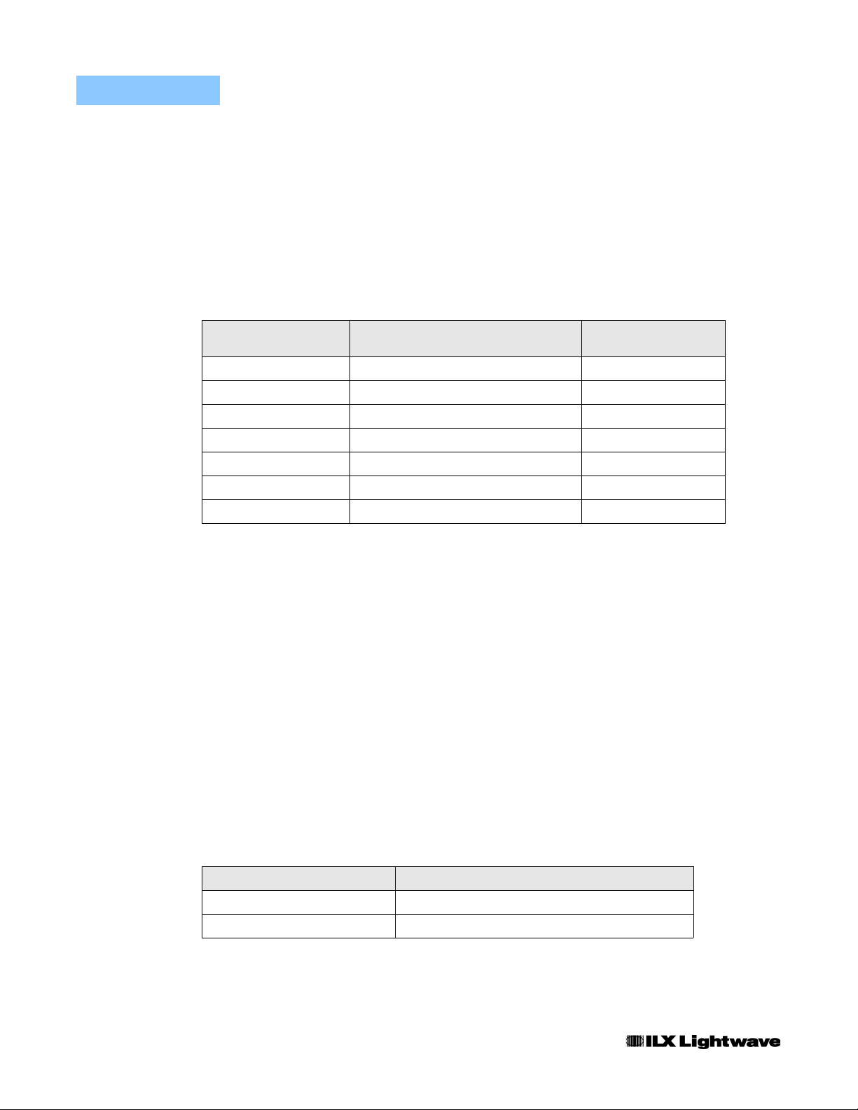
The data of Table 3.1 suggest that long battery life results from maintaining the
batteries as fully charged as possible and that short battery life will result from the
practice of waiting until a low-battery condition is indicated before recharging the
batteries.
If the LDX-3620 is to be stored for long periods, the batteries should be fully
recharged for eight hours every 6-9 months to prevent a permanent loss of
capacity due to self-discharge.
LDX-3620 23
Page 40
CHAPTER 3
MAINTENANCE
Battery Replacement
Battery life in recharge cycles can be estimated from Table 3.1 once one
calculates the average "amp-hours" drawn from the LDX-3620 between
recharges. This is calculated by multiplying the average time the unit is used
between recharges by the average output current setting during use. The
operation time includes the time when the OUTPUT push button is OFF (out)
since turning off the output simply shunts the output current through a short
internal to the LDX-3620.
Table 3.1 Estimated Battery Lifetime
Average Amp-Hours Expected Charge/Recharge Cycles Recharge Cycles with
1.5 1100
2.0 700
2.5 400 1200
3.5 300 700
4.5 200 400
7.0 * 300
9.0 * 200
* Indicates that low battery shutdown will prevent further discharge at these points.
362038 Option
Battery Replacement
The batteries may be replaced by removing the push-on electrical spade
connectors and the sheet-metal tie-downs, which are held in place with 6-32
machine screws. Contact ILX Lightwave for replacement batteries.
24 LDX-3620
Fuse Replacement
The AC power fuse is located on the rear panel of the LDX-3620. Should
replacement be necessary, first disconnect the power cord and turn the AC
POWER switch OFF. Refer to Table 3.2 for the correct fuse ratings.
Table 3.2 Fuse Replacement
Line Voltage Replacement Fuse
100 - 130 VAC 1 Amp, 3 AG, Slow Blow
210 - 250 VAC 1/2 Amp, 3 AG, Slow Blow
Page 41
MAINTENANCE
Calibration
Calibration
The following paragraphs outline the procedures for calibrating the instrument.
Access to the adjustment trimpots on the circuit boards will require that the top of
the instrument be removed. The removal procedure is discussed later in this
chapter.
The equipment required for the calibration procedures must be capable of:
measuring a current of 500 mA to an accuracy of approximately 0.01 mA, and
measuring 1 mA to an accuracy of 0.00005 mA. A good digital multimeter with
5-1/2 digit resolution is usually adequate for this purpose. An oscilloscope is
needed to calibrate the RAMP SPAN of the internal ramp generator.
Note: Calibration of the LDX-3620 should be performed only by qualified personnel.
Potentially lethal or harmful voltages are present and exposed when the top of the unit is
removed.
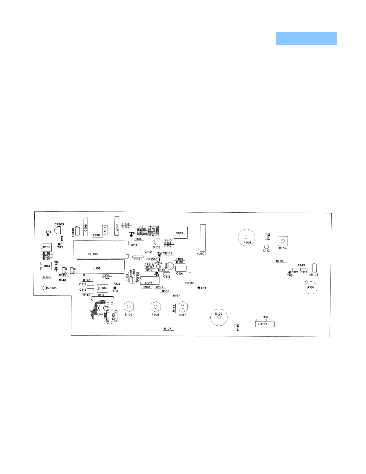
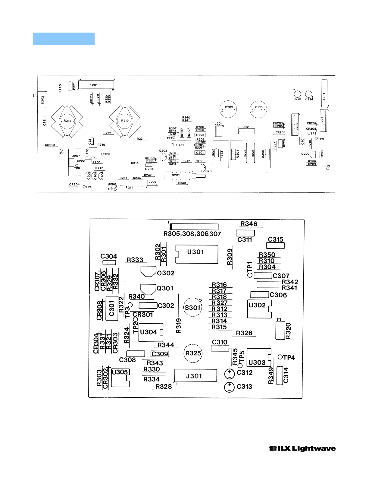
Refer to the component layout diagrams, Figures 3.1through 3.3 to find the
locations of the adjustment trimpots referred to in these procedures.
CHAPTER 3
Figure 3.1 Front Panel Board Layout
06_08 LDX-3620 25
Page 42
CHAPTER 3
MAINTENANCE
Calibration
Figure 3.2 Side Panel Board Layout
26 LDX-3620
Figure 3.3 Rear Panel Board Layout
Page 43

MAINTENANCE
Calibration
CHAPTER 3
Display Calibration
Connect the ammeter across the current output of the LDX-3620 to monitor the
output current. Make the following settings and adjustments:
1 Release the DISPLAY push button to the LASER position (out).
2 Turn the MODULATION mode selector switch to the OFF position.
3 Set the MODE select switch to CONST CURRENT.
4 Turn the current LIMIT knob fully clockwise (CW) to its maximum setting.
5 Turn ON the DC POWER key switch clockwise (CW) to the 200 mA range.
6 Push the OUTPUT switch to its ON position (in).
7 Turn the output adjust knobs clockwise (CW) until the calibration ammeter reads 200.00
mA.
8 Adjust trimpot R133 (on the front panel board) until the display reads 200.00 mA.
9 Turn the DC POWER key switch counter-clockwise (CCW) to the 500 mA range setting
and adjust the OUTPUT ADJUST knobs until the calibration ammeter reads 500.0 mA.
If the output cannot be adjusted to 500.0 mA at this point, then turn the OUTPUT ADJUST
knobs fully clockwise to their maximum settings. Alternately adjust LIMIT pot R229 and
trimmer R103 (located near the OUTPUT switch on the front panel board) until the output
reaches 500.0 mA according to the following guidelines:
9a If the OUTPUT ERROR indicator is lit, adjust LIMIT pot R229 to increase the output
current until the calibration ammeter reads 500.0 mA or continue adjustment a few
turns after the OUTPUT ERROR indicator turns off. If the output current has reached
500.0 mA, proceed to Step 10. If not, proceed to Step 9b.
9b If the OUTPUT ERROR indicator is unlit, adjust R103 to increase the output current
until the calibration ammeter reads 500.0 mA or continue adjustment a few turns after
the OUTPUT ERROR indicator lights. If the output current has reached 500 mA,
proceed to Step 10. If not, proceed to Step 9a.
10 Adjust R221 (located at the top rear of the side panel board) until the display reads 500.0
mA.
MONITOR Current Display Calibration
When the DISPLAY push button is in the MONITOR position, the display reads
the (negative) value of the current input to the photodiode feedback pins 6 and 7
of the rear panel 9 pin connector (J401).
1 After the display has been calibrated, the LDX-3620 can be used to source 1 mA to the
series combination of the photodiode feedback input and calibration ammeter. Make the
following connections:
1a Connect the positive terminal of the calibration ammeter to pin 9 of the rear panel
OUTPUT connector (J401).
06_08 LDX-3620 27
Page 44

CHAPTER 3
OUTPUT ADJUST Calibration
MAINTENANCE
Calibration
1b Connect the negative terminal of the calibration ammeter to pin 7 of the OUTPUT
connector (J401).
1c Connect pin 6 to pin 5 of the OUTPUT connector (J401).
Select the 200 mA current range with the DC power key switch, and set the Output
current to 1.00 mA with the OUTPUT ADJUST knobs.
2 Push the DISPLAY push button to the MONITOR position (in).
3 Adjust R320 (on the rear panel board) until the calibration ammeter and the LDX 3620
display measurements are the same.
After the display has been calibrated the OUTPUT ADJUST span can be
calibrated:
1 Repeat the settings of Steps 1-6 of the Display Calibration section.
2 Turn the OUTPUT ADJUST knobs fully clockwise (CW) to their maximum setting.
3 Adjust R103 (located on the OUTPUT side of the front panel board) until the calibration
ammeter reads 200.0 mA.
LIMIT Current Calibration
The current LIMIT knob must be calibrated to 500 mA at its maximum setting:
1 Repeat the settings of Steps 1-4 of the Display Calibration section.
2 Turn the OUTPUT ADJUST knobs fully clockwise to their maximum settings.
3 Turn the DC POWER range key switch counter-clockwise (CCW) to the 500 mA position.
4 Adjust LIMIT pot R229 until the output current reaches 500 mA.
RAMP SPAN Calibration
An oscilloscope is necessary to monitor the output current waveform in order to
calibrate the RAMP SPAN adjustment.
1 Turn the DC POWER key switch counter-clockwise (CCW) to select the 500 mA range.
Set the output current LIMIT to 201.0 mA using the procedure described in Chapter 2.
2 Turn the OUTPUT ADJUST knobs fully counter-clockwise (CCW) to their minimum setting
and change the output current range to 200 mA with the DC power key switch.
3 Connect an oscilloscope to a resistor load connected across the LDX-3620 current
output.
4 Turn the modulation mode selector switch to the RAMP position.
28 LDX-3620
5 Turn the RAMP SPAN adjustment knob fully clockwise (CW) to its maximum setting.
Page 45

MAINTENANCE
Disassembly
6 Increase the ramp amplitude (with trimmer R116 (located near the center of the front
panel board) until clipping of the output by the current limit circuit at the ramp maximum
can be seen on the oscilloscope. Reverse the adjustment to the point where the clipping
just disappears.
Disassembly
The top cover of the LDX-3620 can be removed after extracting the two
countersunk screws on the sides of the instrument near the rear panel. The cover
is then removed by sliding it rearward and lifting it off. The bottom of the
instrument is removed in a similar fashion.
CHAPTER 3
06_08 LDX-3620 29
Page 46

CHAPTER 3
MAINTENANCE
Disassembly
30 LDX-3620
 Loading...