

Page 1
Operation Manual
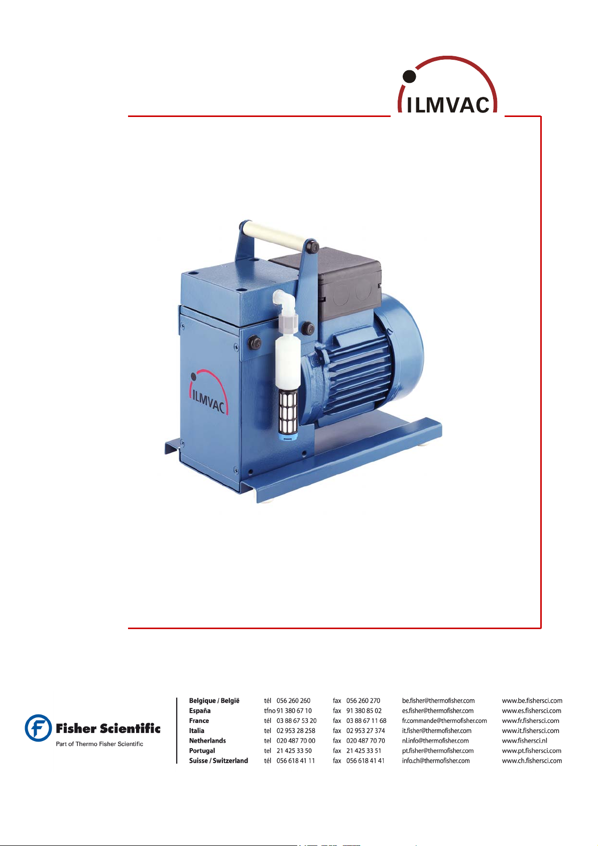
Diaphragm pumps 1-headed
Types MP 301 E
MPC 301 E
4000732
2008-08-19
Page 2

We are constantly working on the further development of all our product types.
Reprinting or reproduction of this manual, including extracts, is not allowed without the prior written permission of
ILMVAC GmbH.
All rights under the copyright laws are expressly reserved by ILMVAC GmbH.
We reserve the right to make changes and amendments.
ILMVAC GmbH
Am Vogelherd 20
98693 Ilmenau, Germany
Telephone: +49 36 77 60 40
Fax: +49 36 77 60 41 10
E-mail: [email protected]
Internet: http://www.ilmvac.de
http://www.ilmvac.com
Page 3

Contents
Contents
1 Important Information.............................................................................................................4
1.1 General Information ..................................................................................................................4
1.2 Target Groups...........................................................................................................................4
1.3 Intended Use.............................................................................................................................4
1.4 Use for an Unauthorized Purpose ............................................................................................4
1.5 Safety Devices ..........................................................................................................................5
1.6 Meaning of the Warning notes ..................................................................................................5
1.7 Product Standards, Safety Regulations....................................................................................5
2 Basic Safety Instructions.......................................................................................................6
2.1 General Information ..................................................................................................................6
2.2 Electricity...................................................................................................................................6
2.3 Mechanical Systems .................................................................................................................6
2.4 Hazardous Substances.............................................................................................................7
2.5 High Temperatures ...................................................................................................................7
3 Description ..............................................................................................................................8
3.1 Design .......................................................................................................................................8
3.2 Principle of Operation ...............................................................................................................8
3.3 Areas of Application ..................................................................................................................8
3.3.1 Materials of the medium-affecting pump parts..........................................................................9
3.4 Scope of Delivery......................................................................................................................9
3.5 Accessories...............................................................................................................................9
4 Technical Data.......................................................................................................................10
4.1 Dimensions .............................................................................................................................10
4.2 Intake Pressure / Pumping Speed – Diagram ........................................................................10
4.3 Device Data.............................................................................................................................11
5 Installation and Operation....................................................................................................12
5.1 Unpacking ...............................................................................................................................12
5.2 Installation and Connection.....................................................................................................12
5.3 Operation ................................................................................................................................12
5.4 Storage....................................................................................................................................13
5.5 Scrap Disposal ........................................................................................................................13
6 Maintenance and Servicing..................................................................................................14
6.1 General Requirements............................................................................................................14
6.2 Maintenance Performed by the User ......................................................................................14
6.2.1 Disassembly............................................................................................................................15
6.2.2 Assembly.................................................................................................................................15
6.2.3 Test .........................................................................................................................................16
6.3 Maintenance by the Manufacturer ..........................................................................................16
6.4 Damage Report.......................................................................................................................16
7 Troubleshooting....................................................................................................................17
8 Spare Parts Overview...........................................................................................................18
8.1 Maintenance kit.......................................................................................................................18
8.2 Exploded view.........................................................................................................................19
8.2.1 Part list diaphragm pumps MP 301 E .....................................................................................20
8.2.2 Part list diaphragm pumps MPC 301 E...................................................................................21
4000732 3
Page 4

Important Information
1 Important Information
1.1 General Information
The ILMVAC Diaphragm Pumps conform to the following directives:
• 2006/95/EC Low Voltage Directive
• 2006/42/EC Machinery Directive
• 2004/108/EC Electromagnetic Compatibility Directive
The CE sign is located on the rating plate. Observe the binding national and local regulations
when fitting the pump into installations.
Our products are sold worldwide and can therefore be equipped with the typical national
plugs and for the various voltages. You will find more information about the available pump
designs under http://www.ilmvac.de.
1.2 Target Groups
This Operating Manual is intended for the personnel planning, operating and maintaining
ILMVAC Diaphragm Pumps.
This group of people includes:
• Designers and fitters of vacuum apparatus,
• Employees working on commercial laboratory and industrial vacuum technology applica-
tions and
• Service personnel for diaphragm pumps
The personnel operating and maintaining the diaphragm pumps must have the technical
competence required to perform the work that has to be done. The user must authorize the
operating personnel to do the work that has to be done. The personnel must have read and
understood the complete Operating Manual before using the diaphragm pumps.
The Operating Manual must be kept at the place of use and be available to the personnel
when required.
1.3 Intended Use
• The layout of the diaphragm pump must be appropriate for the conditions of use. The
user bears the sole responsibility for this.
• The diaphragm pump may only be operated under the conditions stated
– in the "Technical Data" section,
– on the type plate, and
– in the technical specification for the order concerned.
• Diaphragm pumps are approved for extracting, pumping and compressing gases and vapours. If these gases and vapours are toxic or explosive, then the user must observe the
currently valid safety regulations for this application. Special types of diaphragm pumps
are available for aggressive and explosive gases.
1.4 Use for an Unauthorized Purpose
It is forbidden to use the pump for applications deviating from the technical data stated on
the type plate or the conditions stated in the supply contract, or to operate it with missing or
defective protective devices.
4 4000732
Page 5
1.5 Safety Devices
Measures such as the following are for the safety of the operating personnel:
• electrical connection with a protective conductor (operating mode S1) and an earthing
plug,
• Motor protection switch (thermal) and
• “Hot Surface" label on the pump body (warning notice).
The diaphragm pump must not be operated without these elements.
1.6 Meaning of the Warning notes
Take note of the warning notices. They are in the following box:
Important Information
Hazard which may lead to serious injuries or material damage.
1.7 Product Standards, Safety Regulations
ILMVAC Diaphragm Pumps meet the following product standards:
DIN EN 292-1, DIN EN 292-2
DIN EN 1012-2
DIN EN 60204-1
EN 50110-1 (DIN VDE 0105-100)
EN 61010-1 Safety for laboratory devices
EN 50081-1-2
EN 50082-1-2
EN 55014
EN 61000-3-2/3
Directive 2006/42/EC Law and Administration Regulations relating to Machinery
Directive 2002/95/EC RoHS Restriction of use of certain hazardous substances
The following additional safety regulations apply in the FR Germany:
BGV A2 Electrical equipment and operating materials
VBG 5 Power-driven machines
BGR 120 Guidelines for laboratories
BGI 798 BG hazard assessment in the laboratory
Observe the standards and regulations applying in your country when you use the diaphragm pumps.
Safety of machines, basic terminology
Compressors and vacuum pumps
Electrical equipment of machines
Operation of electrical installations
Electromagnetic compatibility (EMC)
Generic specification - Interference resistance
for residential, business and industrial areas, and small businesses
Electromagnetic compatibility (EMC)
Generic specification - Interference emission
for residential, business and industrial areas, and small businesses
Radio disturbance characteristics of electrical equipment and
systems
Electromagnetic compatibility (EMC)
CAUTION ! / WARNING !
4000732 5
Page 6

Basic Safety Instructions
2 Basic Safety Instructions
2.1 General Information
Warning notices must be observed. Disregarding them may lead to damage to health and
property.
The diaphragm pumps must be operated by personnel who can detect impending dangers
and take action to prevent them from materialising.
The manufacturer or authorized authorised workshops will only service or maintain the diaphragm pump if it is accompanied by a fully completed damage report. Precise information
about the contamination (also negative information if necessary) and thorough cleaning of
the diaphragm pump are legally binding parts of the contract.
Contaminated diaphragm pumps and their individual parts must be disposed of in accordance with the legal regulations.
The local regulations apply in foreign countries.
2.2 Electricity
The diaphragm pumps of operation mode S1 are supplied. When the location of operation
mode S1 devices is changed, please note that the testing must be repeated in accordance
with DIN EN 0105, DIN EN 0702 and BGV A2.
The local regulations apply in foreign countries.
Please note the following when connecting to the electrical power supply system:
• The electrical power supply system must have a protective connector according to DIN VDE 0100410 (IEC 60364-4-41).
• The protective connector must not have any breaks.
• The connecting cable must not be damaged.
2.3 Mechanical Systems
Improper use can lead to injuries or material damage. Observe the following instructions:
• Only operate the diaphragm pumps with hoses of the specified dimensions.
• The maximum permissible pressure of 1 bar at the suction connection must not be exceeded.
• Hazardous substances must be separated out as far as this is technically possible before they
reach the pump.
• External mechanical stresses and vibrations must not be transmitted to the pump. Only use flexible
NW 8 laboratory hoses for connecting diaphragm pumps.
• The overpressure generated at the pressure port must not exceed 1 bar.
• The pump must not be used to suck up fluids. Lay the exhaust pipe so that it slopes downwards, so
allowing condensate to flow out of the pump. Collect the condensate and dispose of it in an environmentally compatible manner.
• Prevent dyes exuding.
• Maintain a space of least 20 mm between the pump and adjacent parts in order to enable the pump
to cool.
Solid particles in the pumping medium impair the pumping action and can lead to
damage. Prevent solid particles penetrating into the pump.
CAUTION !
6 4000732
Page 7

2.4 Hazardous Substances
The operating company bears the responsibility for the use of the diaphragm pump.
Hazardous substances in the gases to be pumped can cause personal injuries and property
damage. Pay attention to the warning notices for handling hazardous substances.
The local regulations apply in foreign countries.
Combustible Gases
Examine before switching on whether that can form gas combustible gas/air mixtures which
can be promoted! Consider the regulations of the guideline 1999/92/EC.
Explosive gases
The diaphragm pumps is not certified according to ATEX guidelines 94/9/EC.
Aggressive gases
The MPC series is designed for extracting contaminated gases!
The use of diaphragm pumps of the series MP of ILMVAC GmbH cannot be recommended
for such cases of application!
Especially aggressive gases have to be explicitly checked for material resistance as described in chapter 3.4 and, if necessary, modified.
Poisonous gases
Use a separator when pumping poisonous or harmful gases. Prevent such substances from
leaking out of the appliance or pump. Treat these substances according to the applicable
environmental protection regulations.
Test the strength and leak-tightness of the connecting lines and the connected apparatus.
Prevent environmental poisons, e.g. mercury, getting into the diaphragm pumps.
Fulfil the requirements, for example:
• German Hazardous Substances Regulation (GefStoffV) of 23. December 2004
• Regulations 2006/121/EC (classification, packaging and identification of hazardous sub-
stances),
• Manufacturer's safety data sheets on hazardous substances.
Basic Safety Instructions
2.5 High Temperatures
The diaphragm pump may heat up as a result of the temperature of the gas being pumped
and through compression heat.
Prevent the following maximum permissible temperatures from being exceeded.
• + 40 °C for the environment, and
• + 60 °C for the gas to be pumped.
The motor for single phase alternating current is protected against overload by an integrated
motor protection switch.
4000732 7
Page 8
Description
3 Description
3.1 Design
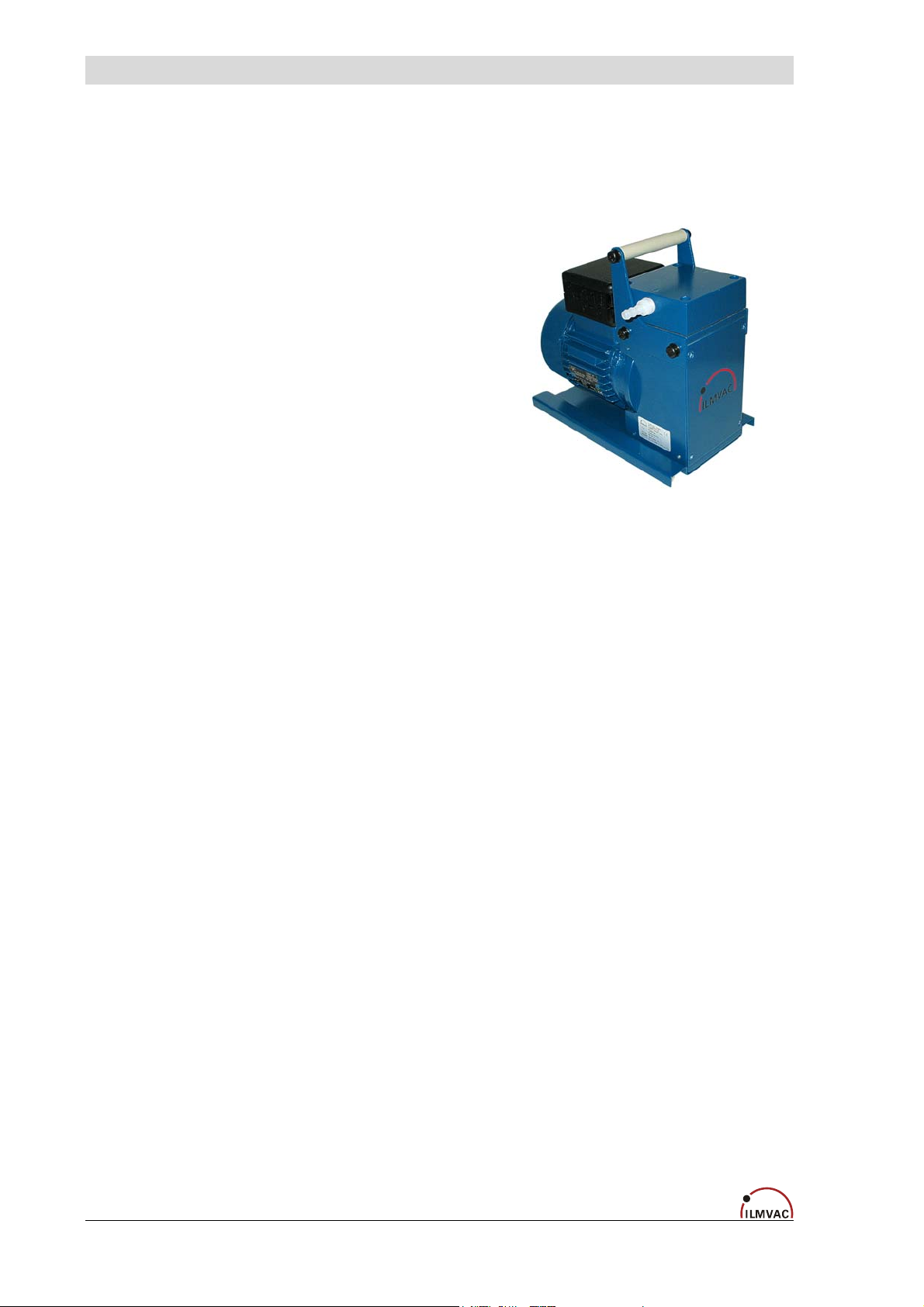
The one-stage diaphragm pump consists of a
pump body and a drive motor.
The pump casing contains the drive unit and
one pump heads.
The pump head contains a diaphragm and
the work valves.
The pump heads are driven via an eccentric
shaft with a connecting rod.
Fig. 1 Diaphragm pump MP 301 E
3.2 Principle of Operation
Motor, eccentric shaft and connecting rod set the diaphragms in stroke movement. This
changes the size of the space between the diaphragms and pump head (pump chamber).
Increasing the size of the pump chamber opens the inlet valve while the outlet valve is
closed (intake process).
Decreasing the size of the pump chamber ejects the gas through the outlet valve.
The valves are actuated by the gas being pumped. A large proportion of fluid in the diaphragm pump minimizes the pumping efficiency.
3.3 Areas of Application
ILMVAC Diaphragm Pumps are intended to:
• Pumping and compressing neutral and aggressive gases and vapours.
• Generating a vacuum down to an ultimate pressure < 75 mbar.
• Use in physical and chemical laboratories in trade and industry.
• Use for vacuum filtration, vacuum distillation and vacuum drying, and other vacuum tech-
nology applications.
8 4000732
Page 9
3.3.1 Materials of the medium-affecting pump parts
Description
Component Standard design MP type Chemical model MPC type
(resistant to aggressive gases)
Connection head /
Pump head
Aluminium
PTFE
with carbon-fibre reinforcing
Seal EPDM EPDM
Screw fitting PA / PP PVDF / PP
Valves PEEK PEEK
Diaphragm
fabric reinforced
with a PTFE layer
fabric reinforced
with a PTFE layer
Connecting elements PP PP
Hose PTFE PTFE
Notes:
PTFE with carbon-fibre reinforcement, electrically conductive (with manufacturer's certificate
of electrical conductivity).
Material resistance to aggressive media see:
“Kunststoff Kautschuk Produkte“, Jahreshandbuch der Verarbeiter 2000/2001 ("Plastic,
Rubber Products“, Annual Handbook of the Processor 2000/2001), Publisher Hoppenstedt
Darmstadt, Vienna, Zurich.
3.4 Scope of Delivery
The scope of delivery is specified in the supply contract.
3.5 Accessories
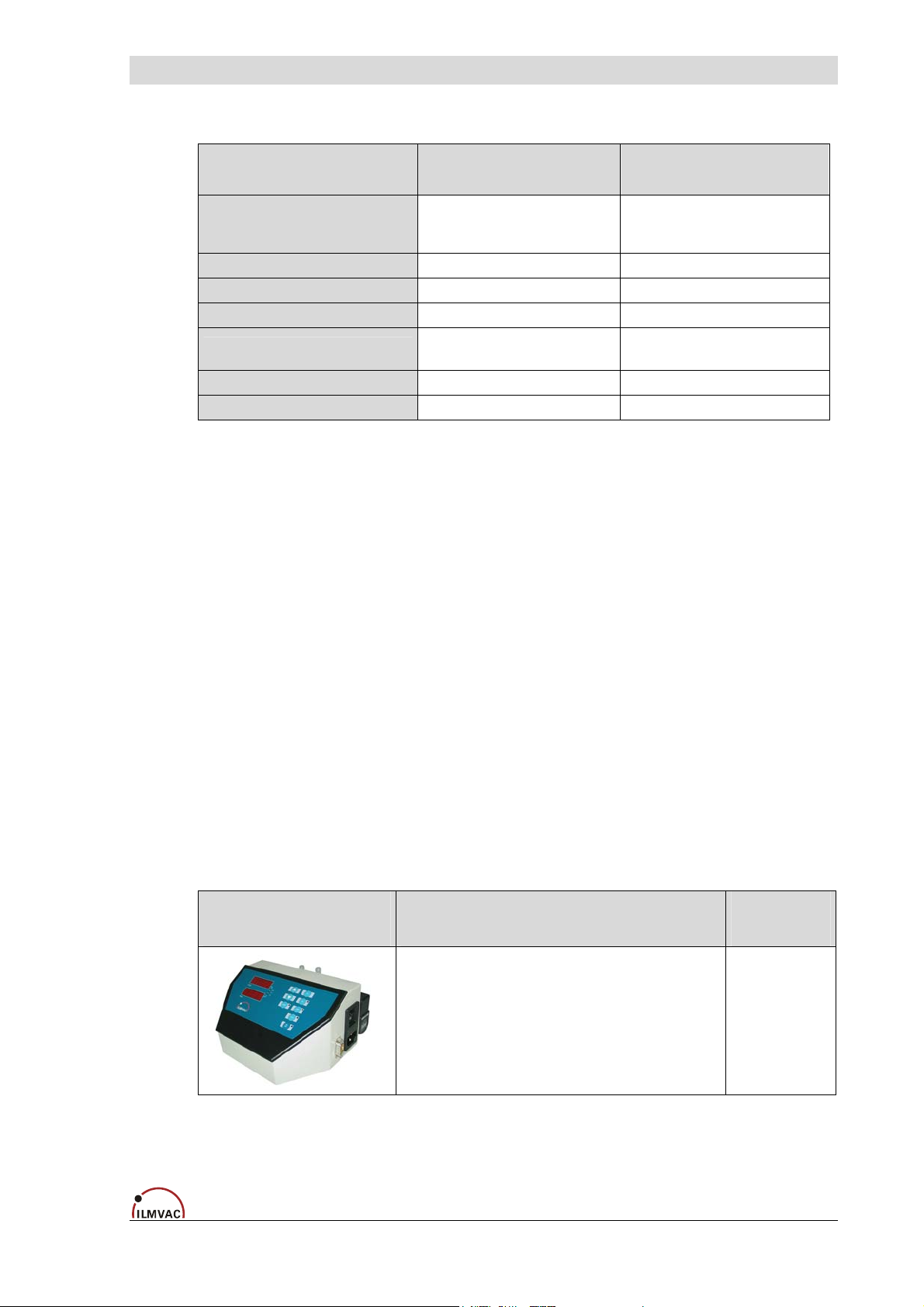
Figure Designation Order no.
Vacuum Control Box VCB 424 cv
For measuring and regulation of vacuum.
600037
4000732 9
Page 10
Technical Data
4 Technical Data
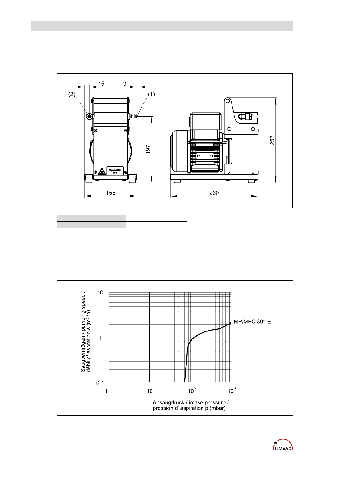
4.1 Dimensions
(1) Suction connection Hose nozzle DN 8
(2) Pressure connection Hose nozzle DN 8 / muffler
Fig. 2 Dimensions
4.2 Intake Pressure / Pumping Speed – Diagram
Fig. 3 Intake Pressure, Pumping Speed
10 4000732
Page 11
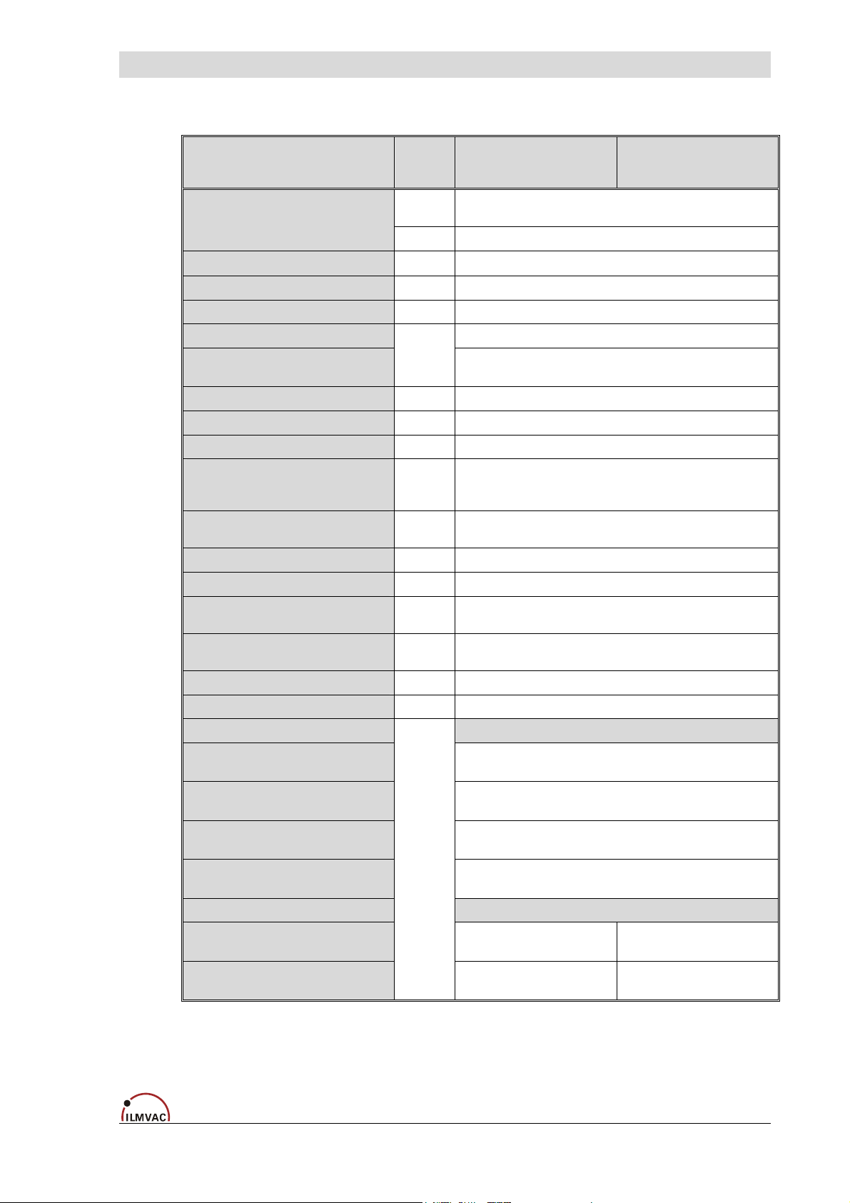
4.3 Device Data
Parameter Unit MP 301 E MPC 301 E
Technical Data
Pumping speed 50/60 Hz
DIN 28432
Ultimate pressure
Max. inlet pressure
Max. outlet pressure
Suction connection
Pressure connection
Ambient temperature
Max. operating gas temperature
Bearing
Reference surface
sound pressure level
DIN 45635 part 13
Voltage / Frequency
(different data upon customer request)
Power
Operating mode
Type of protection (Motor)
DIN EN 60529
Class of insulation
DIN EN 600034-1
Weight
Dimensions (W/D/H)
Order numbers for :
- Mains connection cable IEC
with plug CEE (D)
- Mains connection cable IEC
with plug BS (UK)
- Mains connection cable IEC
with plug type 12 (CH)
- Mains connection cable IEC
with plug NEMA 1-15 (US)
Order numbers for :
- Diaphragm pump 230 V
without mains connection cable
- Diaphragm pump 115 V
without mains connection cable
m3 / h 2.3 / 2.5
l / min 38 / 41
mbar
bar 1
bar 1
Hose nozzle for hose inside diameter 8 mm
-
°C + 10 to + 40
°C + 60
- maintenance-free
dB (A)
V, Hz
W 180
- S 1
- IP 54
- F (160°C)
kg 8.9
mm 162 / 260 / 252
-
Hose nozzle for hose inside diameter 8 mm
230, 50/60 (115, 50/60)
(generally with motor protection switch, switch and plug IEC)
4000732 4000742
4000732-01 4000742-01
< 75
(or muffler)
< 45
825885
825878
825877
825903
4000732 11
Page 12
Installation and Operation
5 Installation and Operation
5.1 Unpacking
Carefully unpack the diaphragm pump.
Check the pump for:
• Transport damage,
• Conformity with the specifications of the supply contract (type, electrical supply data),
• Completeness of the delivery.
Please inform Ilmvac GmbH without delay if there are discrepancies between the delivery
and the contractually agreed scope of delivery, or if damage is detected.
Please take note of the general terms of business of ILMVAC GmbH.
In case of a claim under warranty, the device must be returned in packaging that is
suitable for protecting it during transport.
5.2 Installation and Connection
1. Set the diaphragm pump on a flat and horizontal surface.
2. Remove the protective caps on the suction port.
3. Prepare the connections.
4. Connect the DN 8 vacuum line to the suction connection.
5. Connect the diaphragm pump to the electrical supply.
6. If the exhaust pipe is to be connected, fit the supplied hose nipple. The sound absorber is
to be mounted when the exhaust pipe is free.
The muffler used in the chemical area has only a limited chemical durability.
5.3 Operation
CAUTION !
Observe the basic safety instructions when using the pump.
The diaphragm pump is switched on and off at the operating switch.
12 4000732
CAUTION !
Page 13
5.4 Storage
The pumps are to be stored in a low-dust, interior room within the temperature range from
+ 5 to + 40 °C and at a relative air humidity < 90%.
Leave the protective elements on the suction and pressure ports. Another equally good protection may be used.
5.5 Scrap Disposal
The diaphragm pumps must be disposed of in accordance with the 2002/96/EC guideline and the specific national regulations.
Installation and Operation
CAUTION !
Contaminated diaphragm pumps must be decontaminated according to the laws.
4000732 13
Page 14
Maintenance and Servicing
6 Maintenance and Servicing
6.1 General Requirements
• Check the pump daily for unusual running noises and heat building up on the surface of
the pump.
• We recommend changing the diaphragm after 10,000 operating hours. The user may
specify that the exchange be made earlier, depending upon the application process.
• Check the electrical and vacuum connections daily.
6.2 Maintenance Performed by the User
Only perform the work that is described here, and that which is permitted to be done
by the user.
All other maintenance and service work may only be performed by the manufacturer
or a dealer authorized by him.
Beware of the pump parts being possibly contaminated by hazardous substances.
Wear protective clothing if there is contamination.
Scope of permissible work:
• Open and remove the pump heads
• Inspect the pump chambers, diaphragms and valves
• Deposits in the inside of the pump must be cleaned out
• If necessary change the diaphragms, valves and seals.
Tools required:
• Order no. 826801 Pin type face wrench, adjustable, size 3
• Order no. 826801-6 Allan key, size 4
WARNING !
14 4000732
Page 15
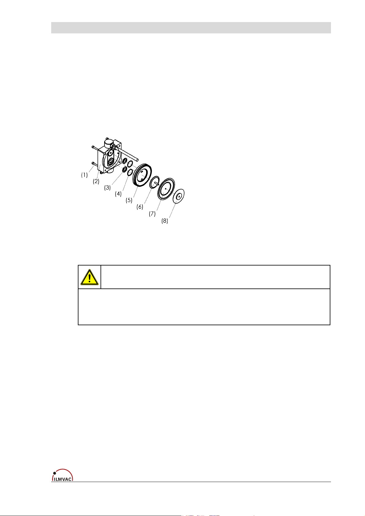
6.2.1 Disassembly
1. Disconnect the power supply and ensure that it cannot be switched on again.
2. Remove four machine screws (1) from each connection head with an Allan key, size 4.
3. Lift off the connection head (2) and the pump head (5). The valves (3), o-rings (4) and diaphragm (7) are now freely exposed.
4. Loosen the diaphragm (7) at the strain washer (6) by turning the size 3 pin type face
wrench anticlockwise.
5. Clean the valves (3), the pump head (5) and the diaphragm (7) with a soft cloth and acetone.
6. Check that the drive is in good working order.
Maintenance and Servicing
Fig. 4 Disassembly, assembly
Renew defective parts, if necessary ! Wear protective gloves!
Parts must be renewed at the intervals stated in this Operating Manual or as specified by the user internally.
Do not clean with compressed air !
6.2.2 Assembly (Fig. 4)
1. Use the size 3 pin-type face wrench to tighten the pressure disc (8), the diaphragm (7)
and the strain washer (6) with the correct torque of 2 - 4 Nm.
2. Bring the connecting rod (see fig. 5) and the diaphragm (7) into the central position.
3. Replace the pump head (5).
4. Insert the valves (3) and the o-rings (4).
Ensure that they are lying completely flat. Do not insert the burred side facing the sealing
surface. Align the connection head flush with the pin.
5. Tighten the four machine screws (1) symmetrically with a torque of 3 to 4 Nm.
WARNING !
4000732 15
Page 16
Maintenance and Servicing
6.2.3 Test
• Connect a vacuum measuring device to the suction connector and measure the ultimate
pressure.
If the device is working properly, then the figure stated in the technical data must be attained within a maximum of one minute.
• The pump must not make any abnormal noises.
• Moving parts must not touch each other.
6.3 Maintenance by the Manufacturer
Repairs and maintenance going beyond the extent of the work described in chapter 6.2 or
reconditioning or modification may only be performed by the manufacturer or authorized
workshops.
The user shall be liable for the consequences of an incorrect damage report or a
contaminated pump. The statements in the damage report are legally binding.
6.4 Damage Report
You find the form of the damage report to the Download on our web page
http://www.ilmvac.de and/or. http://www.ilmvac.com in the menu "service" and "Downloads".
If you should not have an entrance to the Internet, you can request the form also gladly with
us, company Ilmvac GmbH.
Incomplete or incorrectly completed damage reports may endanger the service personnel!
Give full information in the damage report, in particular regarding a possible contaminating.
WARNING !
WARNING !
16 4000732
Page 17
7 Troubleshooting
During the warranty period, intervention in the diaphragm pumps and accessory components
may only be made by ILMVAC GmbH.
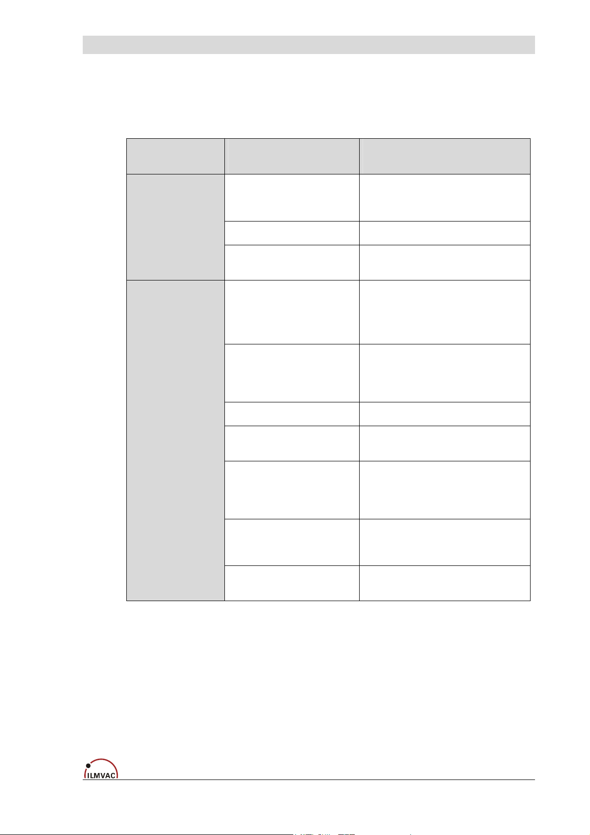
Trouble Cause Action
Troubleshooting
Diaphragm pump
does not start
The diaphragm
pump does not
generate a
vacuum or only
an inadequate
one
No power supply to the
motor
Motor defective Exchange by service shop.
Pump body defective Exchange or repair by service
Connected apparatus
leaks,
connecting elements
leak
Diaphragm pump leaks
(pipes or hoses)
Pump head leaks Repair by service shop.
Diaphragm defective Repair by the service workshop
Valves are dirty Clean condensates and foreign
Electrical system to be checked
by a qualified electrician.
shop.
Identify and seal the leak, replace
the seals and hoses if necessary.
Check the hose connections between the pump heads,
replace the hoses and screwed
clamping rings if necessary.
or the user.
objects out of the valves.
Cleaning by the service workshop
or the user.
Valves defective Replace valves
Repair by the service workshop
or the user.
Diaphragm pump is dirty Cleaning by the service workshop
or the user.
4000732 17
Page 18
Spare Parts Overview
8 Spare Parts Overview
The spare parts lists contain all the spare parts and all the information necessary for ordering.
When ordering, please quote the description, quantity, serial number and order number!
Ilmvac is not liable for any damage caused by the installation of any parts not supplied by the manufacturer.
8.1 Maintenance kit
Designation Order no.
Maintenance kit 402046
The maintenance kit consists of:
CAUTION !
Designation Piece Order no.
O-ring ø 25 x 2 2 829250-1
Valve 2 400656
Diaphragm 1 400732
Caution, the number of supplied construction units in the maintenance set
corresponds to the maximum need of the series!
18 4000732
Page 19
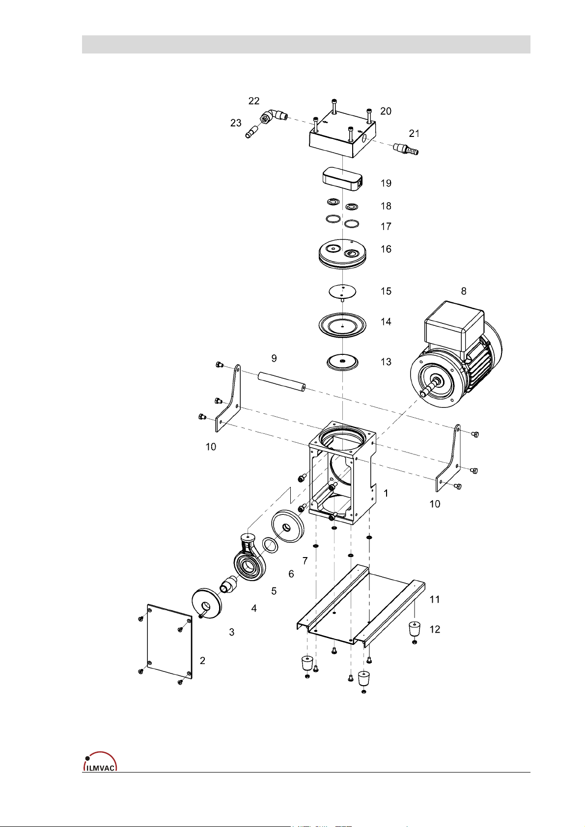
8.2 Exploded view
Spare Parts Overview
Fig. 5 Exploded view MPC 301 E
4000732 19
Page 20
Spare Parts Overview
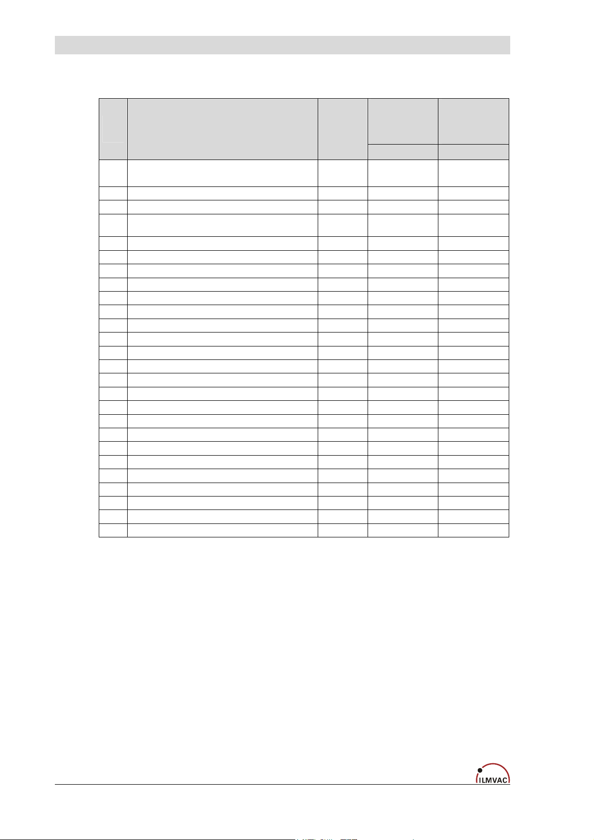
8.2.1 Part list diaphragm pumps MP 301 E
Item
no.
Basic pump complete *)
(consisting of position: 1 – 8)
1 Casing 1 400640 400640
2 Cover plate 1 400641 400641
Drive complete
(consisting of position: 3 – 7)
3 Centrifugal mass 1 400649 400649
4 Eccentric 1 400648-01 400648-01
5 Piston rod with ball bearing 1 400647-01 400647-01
6 Close tolerance spacer 25 x 35 x 1 1 824957-1 824957-1
7 Mass balance 1 400678-2 400678-2
8 Motor …V; 50/60 Hz; 0.18 kW 1 826420 826422-1
9 Handle 1 400964 400964
10 Handle bracket 2 400963 400963
11 Pump bracket 1 400962 400962
12 Rubber pad 4 829150 829150
13 Pressure washer 1 400680 400680
14 Diaphragm 1 400732 400732
15 Tightening washer 1 400617 400617
16 Pump head 1 400643-01 400643-01
17 O-ring EPDM, ø 25 x 2 2 829250-1 829250-1
18 Valve 4 400656 400656
19 Aluminium insert 2 400902-01 400902-01
20 Connection head 2 400901 400901
21 Hose nozzle PP, DN 8 - M12 x 1 1 710798-04 710798-04
22 Threaded elbow joint 10 - PP, M12 x 1 1 829972 829972
23 Hose sleeve 1 829924-1 829924-1
24 Muffler A 10 (provided) 1 400941 400941
*) The “basic pump” module (items 1 – 8) can only be supplied complete under order number 400733-16 or
400733-17
Designation Piece
MP 301 E
230 V
(Order no.
4000732)
Order no. Order no.
1 400733-16 400733-17
1 400843-02 400843-02
MP 301 E
115 V
(Order no.
4000732-01)
20 4000732
Page 21
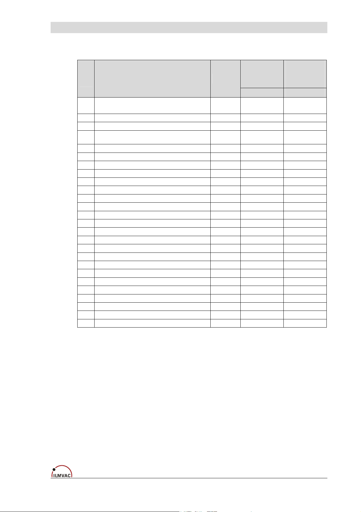
8.2.2 Part list diaphragm pumps MPC 301 E
Item
no.
Basic pump complete *)
-
(consisting of position: 1 – 8)
1 Casing 1 400640 400640
2 Cover plate 1 400641 400641
Drive complete
-
(consisting of position: 3 – 7)
3 Centrifugal mass 1 400649 400649
4 Eccentric 1 400648-01 400648-01
5 Piston rod with ball bearing 1 400647-01 400647-01
6 Close tolerance spacer 25 x 35 x 1 1 824957-1 824957-1
7 Mass balance 1 400678-2 400678-2
8 Motor …V; 50/60 Hz; 0.18 kW 1 826420 826422-1
9 Handle 1 400964 400964
10 Handle bracket 2 400963 400963
11 Pump bracket 1 400962 400962
12 Rubber pad 4 829150 829150
13 Pressure washer 1 400680 400680
14 Diaphragm 1 400732 400732
15 Tightening washer 1 400707 400707
16 Pump head 1 400705-02 400705-02
17 O-ring EPDM, ø 25 x 2 2 829250-1 829250-1
18 Valve 4 400656 400656
19 PTFE insert 1 400902 400902
20 Connection head 2 400901 400901
21 Hose nozzle PP, DN 8 - M12 x 1 1 710798-04 710798-04
22 Threaded elbow joint 10 - PP, M12 x 1 1 829972 829972
23 Hose sleeve 1 829924-1 829924-1
24 Muffler A 10 (provided) 1 400941 400941
Designation Piece
*) The “basic pump” module (items 1 – 8) can only be supplied complete under order number 400733-16 or
400733-17
Spare Parts Overview
MPC 301 E
230 V
(Order no.
4000742)
Order no. Order no.
1 400733-16 400733-17
1 400843-02 400843-02
MPC 301 E
115 V
(Order no.
4000742-01)
4000732 21
 Loading...