

Page 1

Quick Reference Guide
Illustra Pro PTZ Outdoor Housing
8200-1199-02 A0
Page 2

Notice
The information in this manual was current when published. The manufacturer reserves the right to revise and improve its products.
All specifications are therefore subject to change without notice.
Copyright
Under copyright laws, the contents of this manual may not be copied, photocopied, reproduced, translated or reduced to any
electronic medium or machine-readable form, in whole or in part, without prior written consent of Tyco Security Products © 2015 and
its Respective Companies. All Rights Reserved.
Tyco Security Products
6600 Congress Avenue
Boca Raton, FL 33487 U.S.A.
Customer Service
Thank you for using Tyco Security Products. We support our products through an extensive worldwide network of dealers. The dealer
through whom you originally purchased this product is your point of contact if you need service or support. Our dealers are
empowered to provide the very best in customer service and support. Dealers should contact Tyco Security Products at (800) 5076268 or (561) 912-6259 or on the Web at www.illustracameras.com.
Trademarks
The trademarks, logos, and service marks displayed on this document are registered in the United States [or other countries]. Any
misuse of the trademarks is strictly prohibited and Tyco Security Products will aggressively enforce its intellectual property rights to
the fullest extent of the law, including pursuit of criminal prosecution wherever necessary. All trademarks not owned by Tyco Security
Products are the property of their respective owners, and are used with permission or allowed under applicable laws.
Product offerings and specifications are subject to change without notice. Actual products may vary from photos. Not all products
include all features. Availability varies by region; contact your sales representative.
License Information
Your use of this product is governed by certain terms and conditions. Please see the detailed license information at the end of this
manual.
ii
Page 3

Table of Contents
Illustra Pro PTZ Outdoor Housing
To the Installer . . . . . . . . . . . . . . . . . . . . . . . . . . . . . . . . . . . . . . . . . . . . . . . . . . . . . . 1
What’s in the box . . . . . . . . . . . . . . . . . . . . . . . . . . . . . . . . . . . . . . . . . . . . . . . . . . 1
Standard Items . . . . . . . . . . . . . . . . . . . . . . . . . . . . . . . . . . . . . . . . . . . . . . . . . . 1
Feature Plus Version . . . . . . . . . . . . . . . . . . . . . . . . . . . . . . . . . . . . . . . . . . . . . 1
Additional Supplies (not in box) . . . . . . . . . . . . . . . . . . . . . . . . . . . . . . . . . . . . . . . 2
Tools Required . . . . . . . . . . . . . . . . . . . . . . . . . . . . . . . . . . . . . . . . . . . . . . . . . . . . 2
Installing the Outdoor Housing . . . . . . . . . . . . . . . . . . . . . . . . . . . . . . . . . . . . . . . . . . 3
Specifications . . . . . . . . . . . . . . . . . . . . . . . . . . . . . . . . . . . . . . . . . . . . . . . . . . . . 15
Mechanical Details and Dimensions . . . . . . . . . . . . . . . . . . . . . . . . . . . . . . . . . . 15
i-iii
Page 4

Table of Contents
i-iv Quick Reference Guide
Page 5

To the Installer
This guide assumes that the outdoor mounting structure to which the housing is attached is in
place and that data and power cables have been pulled to the installation site.
For the purpose of this guide we are installing the Illustra Pro PTZ camera to an EndCap Mount
(ROENDC).
1. The installation shall be performed by a qualified person in accordance to all local regulations.
2. This equipment requires the use of an NEC class 2 or Certified Limited Power Source (LPS).
What’s in the box
Standard Items
• Quick Reference Guide
Illustra Pro PTZ Outdoor Housing
• Illustra Pro PTZ Camera CD
• Illustra Pro PTZ Outdoor Camera Assembly
• Illustra Pro PTZ Outdoor Bubble Assembly (in separate box)
• Pendant Adapter
• Threaded Adapter
•Lock Nut
• External Safety Lanyard
• Lanyard Lock and Release Pin
• Tamperproof Torx Wrench
• HEX L-Key Tool
• Weather proof Ethernet Connector
• Power Cable
• Desiccant bag and clip
Feature Plus Version
• Alarm Cable
• Audio Cable
• Breakout Box Assembly
1
Page 6

Illustra Pro PTZ Outdoor Housing
Additional Supplies (not in box)
ADSPOT - Power Supply, one output, 120/240 VAC to 24 VAC
Tools Required
• 6.6mm (1/4in) fixed-handle nut driver for Torx bit
• Wire cutters and strippers
• 2.5mm (0.1in) slotted screwdriver
2 Quick Reference Guide
Page 7
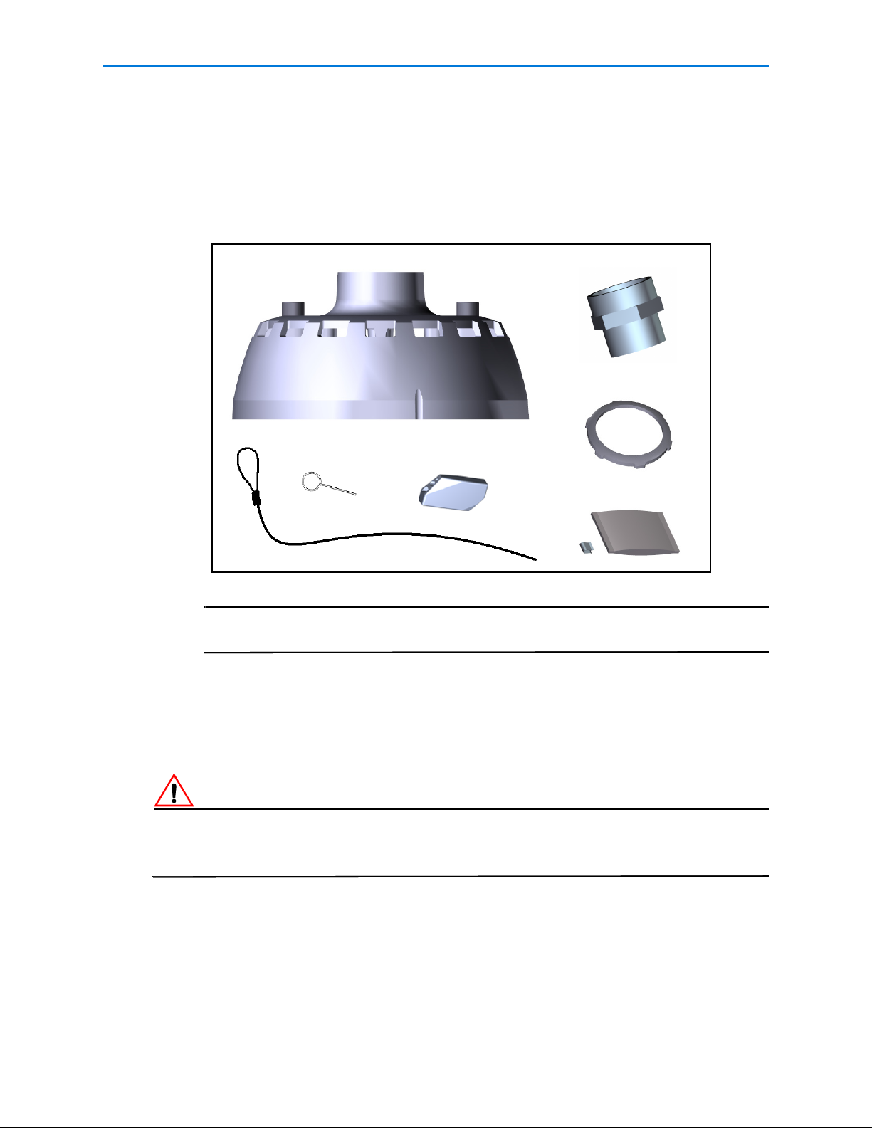
Installing the Outdoor Housing
Note
Pendant Adaptor
Threaded Adaptor
Lock Nut
Safety Lanyard
Lanyard Lock
Release Pin
Desiccant bag and clip
The following describes the installation procedure for the Illustra Pro PTZ Outdoor Camera
Housing.
1 Remove the pendant adapter, threaded adapter, lock nut, external safety lanyard and
lanyard lock from the packaging.
Illustra Pro PTZ Outdoor Housing
The threaded adapter and lock nut will be required for mounting options that use
the EndCap Mount (ROENDC).
2 Cut a 30cm (12in) length of teflon tape.
3 Apply the teflon tape to the threads on both ends of the threaded adapter.
4 Attach the threaded adapter to the pendant adapter and tighten to secure.
5 Attaching to the EndCap Mount (ROENDC):
If the Illustra Pro PTZ Outdoor Housing is being attached to an existing mount it is essential that
the EndCap (ROENDC) is replaced. Please contact your Tyco Security Products Sales
Representative for further information.
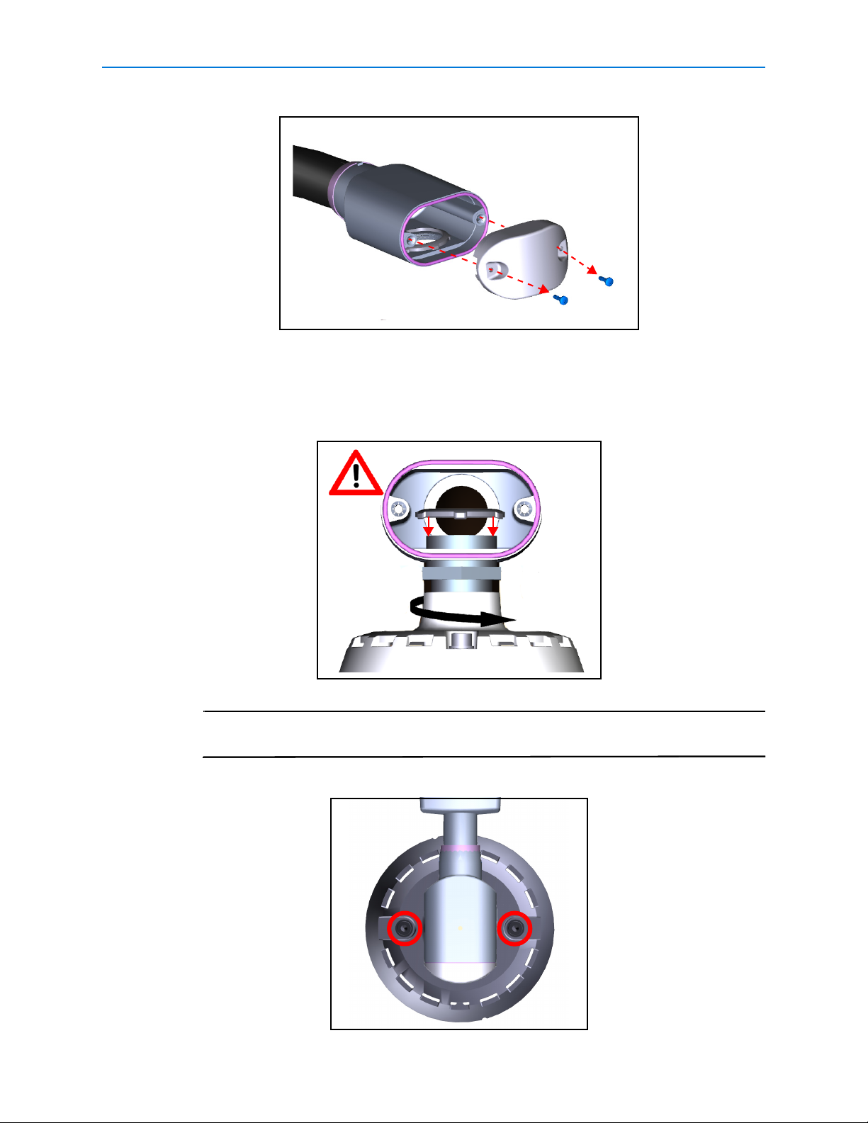
a Remove the access cover from the EndCap mount as seen in Figure 1.
3
Page 8
Illustra Pro PTZ Outdoor Housing
Note
Figure 1
b Align the pendant adapter with the EndCap and rotate clockwise until approximately
6mm of the threaded adaptor is visible inside the EndCap.
c Attach the lock nut to the threaded adaptor and hold while rotating the pendant cap
until secure as seen in
Figure 2.
Figure 2
When securing the pendant adapter ensure that the two M8 screws can be easily
accessed. This can be seen in Figure 3.
Figure 3
4 Quick Reference Guide
Page 9
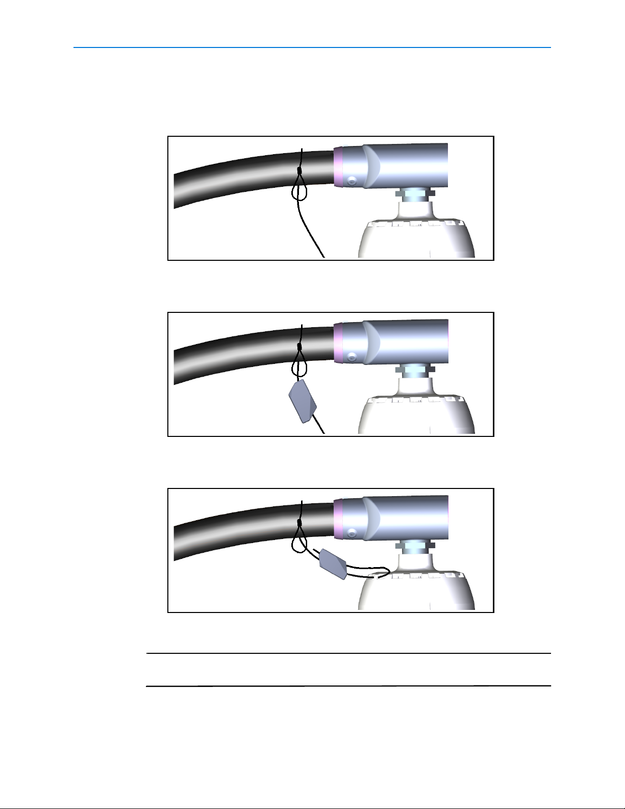
6 Attach the External Safety Lanyard:
Note
a Wrap the safety lanyard around the pipe and thread end through the loop as seen in
Figure 4.
b Attach the lanyard lock by threading the end of the safety lanyard through the hole in
the lanyard lock as seen in
Figure 5.
Illustra Pro PTZ Outdoor Housing
Figure 4
Figure 5
c Feed the end of safety lanyard through vent slots on the pendant adaptor and back
through the lanyard lock as seen in
Figure 6.
Figure 6
d Pull the excess safety lanyard through the lanyard lock to remove the slack.
To remove the lanyard lock, insert the supplied release pin into the pin hole at
either end of the lanyard lock and pull to release the cable.
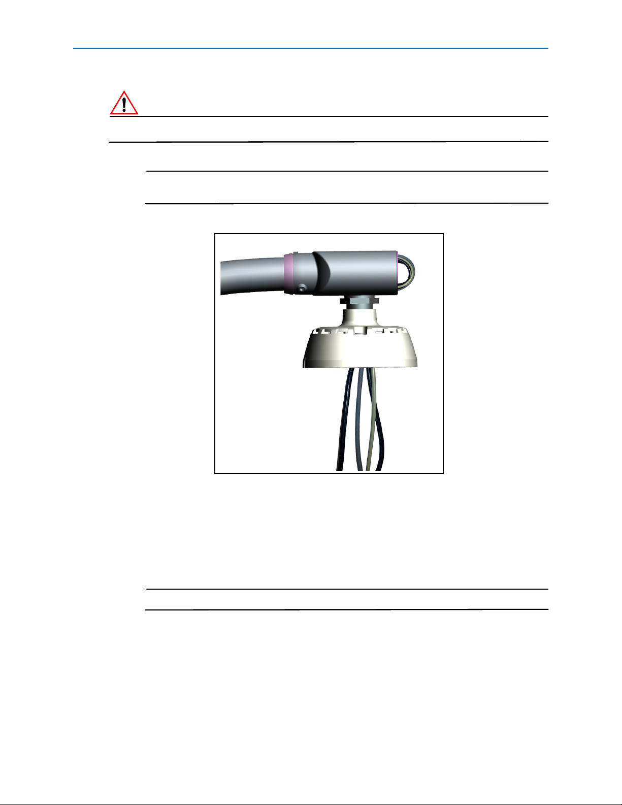
7 Route the supplied cable ends through the EndCap mount and through the pendant
adapter. We recommend that you form an external loop with the cables and then feed
them through the pendant adapter as seen in
Figure 7, this allows freedom of movement
5
Page 10
Illustra Pro PTZ Outdoor Housing
Note
Note
in the cables when attaching the outdoor housing in later steps.
If audio cables are to be extended beyond 30m in length, they must be shielded.
For ease of installation the power, alarm and audio cables should be routed
through first, followed by the Ethernet cable.
Figure 7
8 Terminate the network cable using the supplied weather proof Ethernet connector.
9 Remove the outdoor camera housing from the packaging.
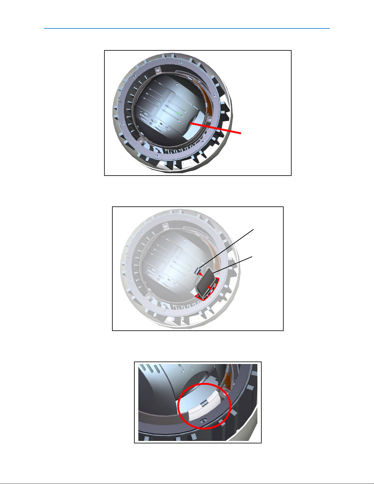
10 Insert desiccant bag:
a Rotate the camera to the position shown in Figure 8, this will allow for space while
inserting the desiccant bag.
Avoid touching the lens during positioning and installation of the desiccant bag.
6 Quick Reference Guide
Page 11
Illustra Pro PTZ Outdoor Housing
Avoid touching the
lens during position-
ing and installation
of the desiccant bag
Clip
Desiccant
Bag
Figure 8
b Insert the desiccant bag in the space between the camera mounting bracket and the
inside surface of the housing as seen in
Figure 9.
Figure 9
c Fold the top edge of the desiccant bag over the camera mounting bracket and secure
with the clip as seen in
Figure 10.
Figure 10
7
Page 12
Illustra Pro PTZ Outdoor Housing
Note
Note
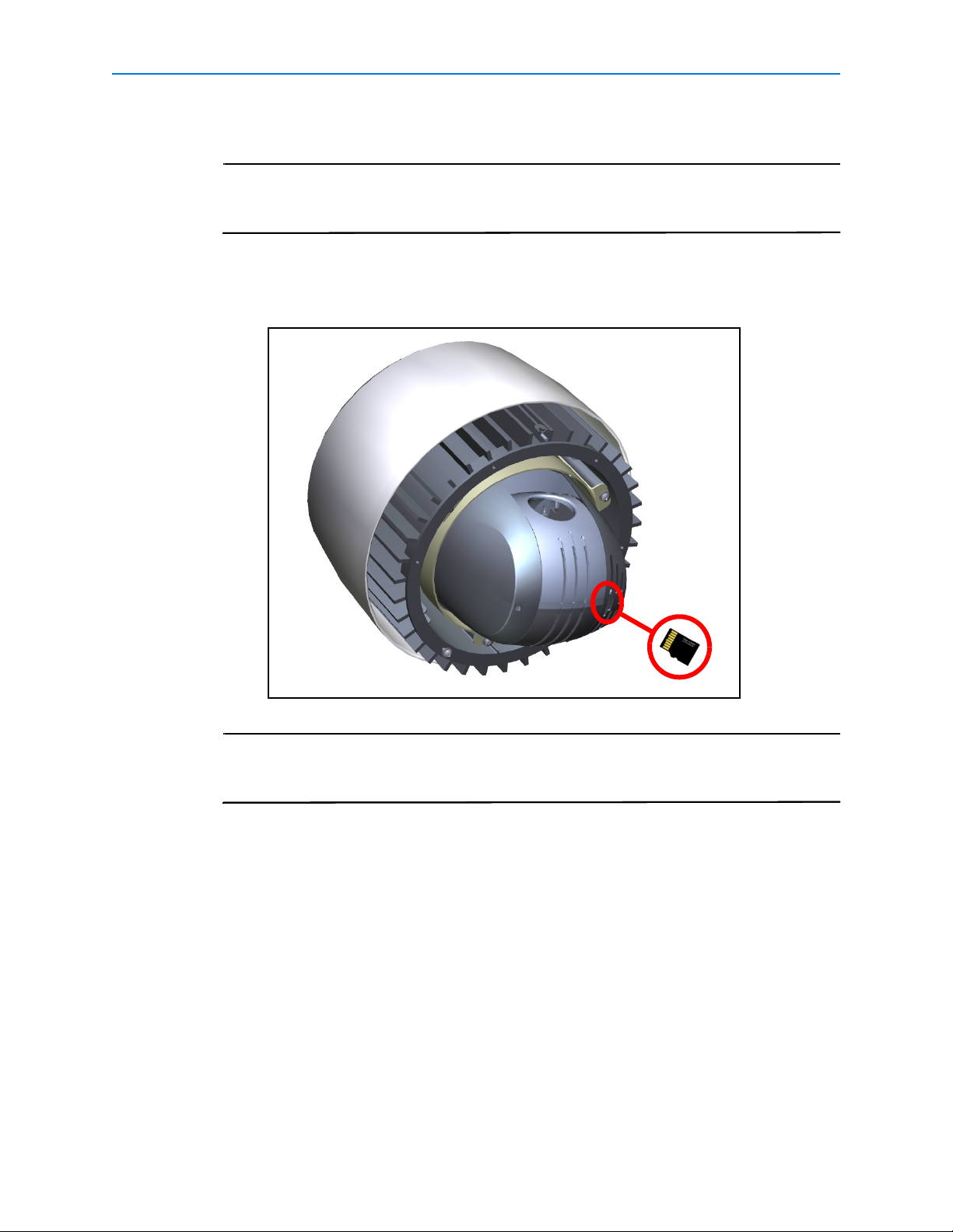
11 If required, a microSD memory card can be installed in the dome:
The microSD card is an optional accessory and is not supplied with the dome. The
maximum size of microSD card that can be used with the dome is 32GB. Contact
your Tyco Security Products representative for further information.
a Align the microSD card with the memory card slot in the dome as shown, the gold-
colored contacts should face towards the camera lens as seen in
Figure 11.
Figure 11
Push the microSD card into the memory card slot until it locks into position.To
remove the microSD card push the card gently until it disengages from the dome.
Remove the microSD card.
12 Attach the bubble assembly:
a Remove the bubble assembly from the packaging.
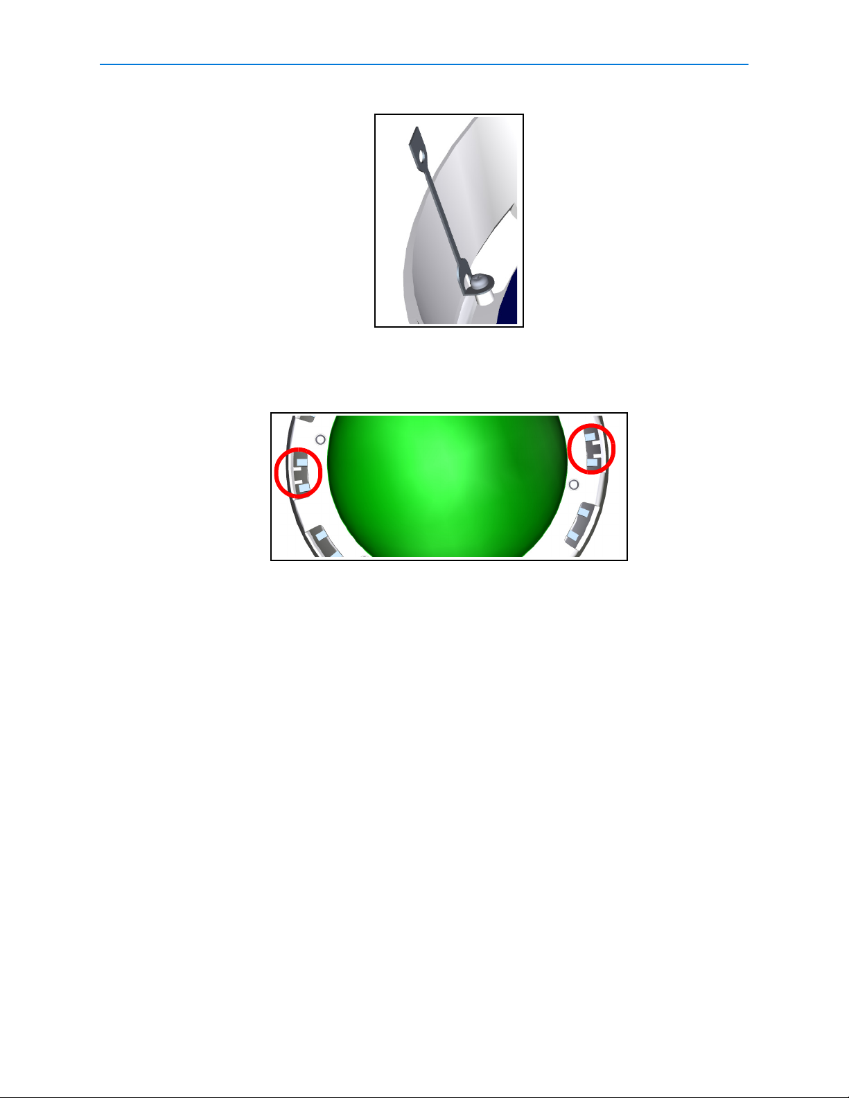
b Attach the plastic lanyard on the housing to the screw on the inside of the trim ring of
the bubble assembly.
c It may be necessary to orientate the plastic lanyard to the position shown in Figure
12. This will ensure that the plastic lanyard does not become trapped between the
bubble assembly and the camera housing and will aid with alignment.
8 Quick Reference Guide
Page 13
Illustra Pro PTZ Outdoor Housing
Figure 12
d Align the bubble assembly with the holes on the outdoor housing flange. The location
ribs on the trim ring will fit between the fins on the outside of the housing as seen in
Figure 13.
Figure 13
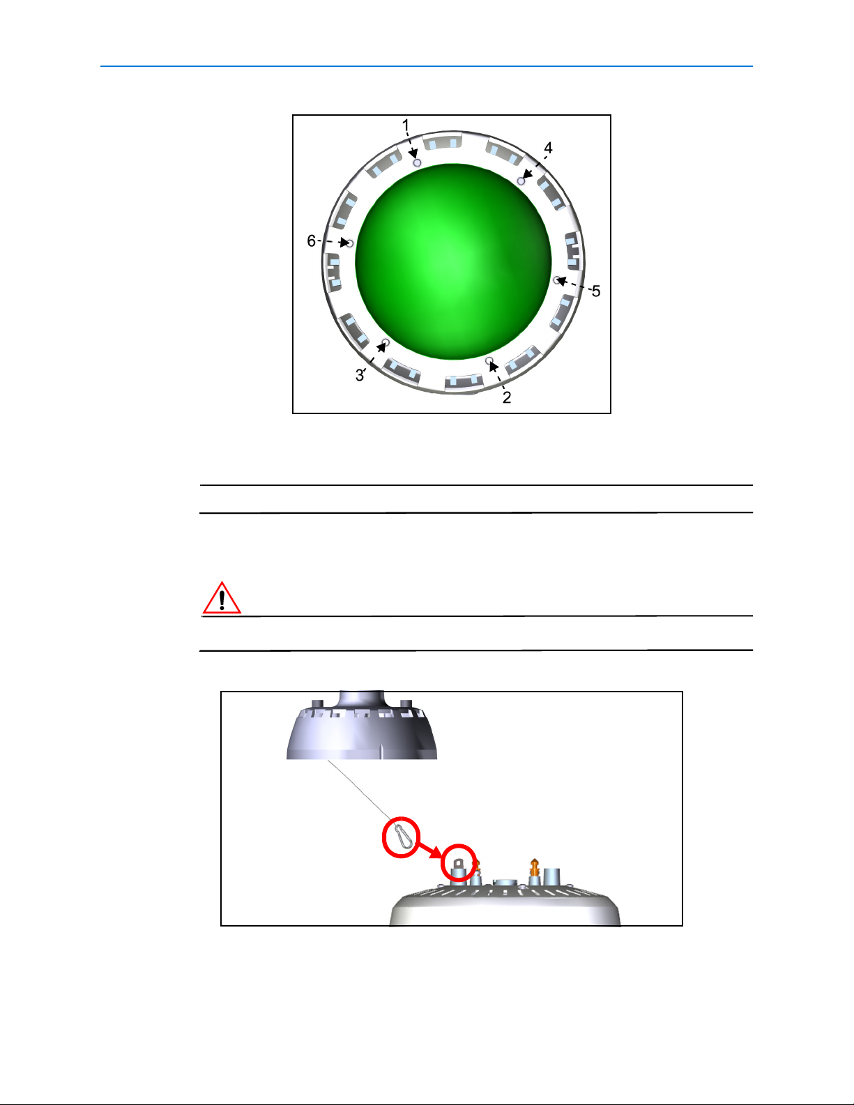
e Loosely tighten the six M4 screws using the tamperproof torx wrench in the sequence
shown in
Figure 14.
9
Page 14
Illustra Pro PTZ Outdoor Housing
Note
Figure 14
f Repeat the process and securely tighten each screw using the tamperproof torx
wrench in the sequence shown in
Figure 14.
Do not overtighten the screws as they may damage the trim ring assembly.
13 Attach the clip on the safety lanyard in the pendant adaptor to the L hook on base of the
outdoor camera housing as seen in
Figure 15.
Ensure that the clip is securely attached.
Figure 15
* The cables have been removed from drawing for clarity
10 Quick Reference Guide
Page 15
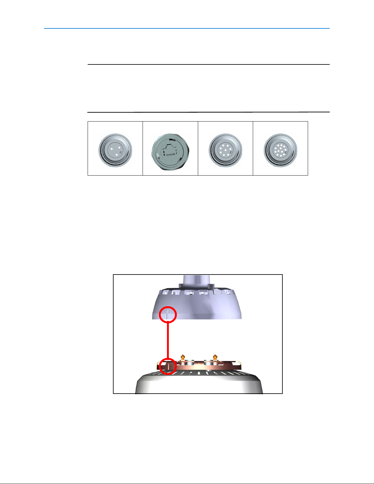
14 Connect the cables to the outdoor camera housing:
Note
1 The alarms and audio ports are only available on the Feature Plus version of
the Illustra Pro PTZ Outdoor Housing, these ports will have watertight covers
on all other versions.
2 For ease of installation connect power, alarm and audio cables before
connecting the Ethernet cable.
Power Ethernet Audio Alarms
a When connecting power, audio and alarm cables, align the rib on the plug (end of
cable) with the corresponding notch on the receptacle (base of housing).
Insert the plug and rotate the collar clockwise to secure.
Illustra Pro PTZ Outdoor Housing
b When connecting the Ethernet cable plug in RJ45 connector.
Rotate the outer collar to secure.
15 Push excess cable the through pendant adaptor into the end cap.
16 Align the notch on the outdoor camera housing with the corresponding notch on the
pendant adapter as seen in
Figure 16.
Figure 16
* The cables have been removed from drawing for clarity
11
Page 16
Illustra Pro PTZ Outdoor Housing
Note
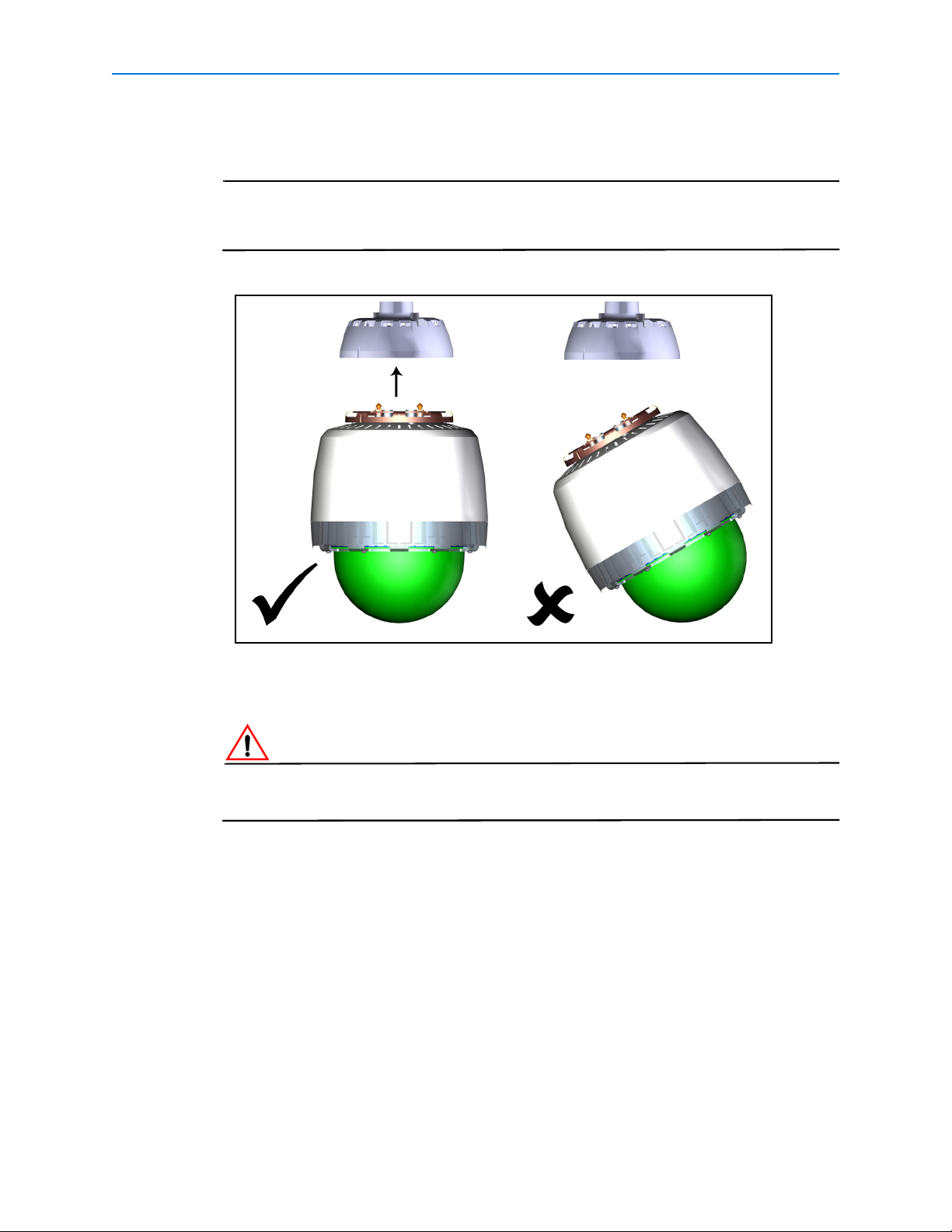
17 Using both hands to provide even pressure insert the outdoor camera housing into the
pendant adapter until in the home position.
Do not angle the outdoor camera housing when inserting it into the pendant
adapter. If the outdoor camera housing is inserted at an angle the bayonet lock
pins will not fully engage. Reference Figure 17.
Figure 17
* Cables have been removed from drawing for clarity
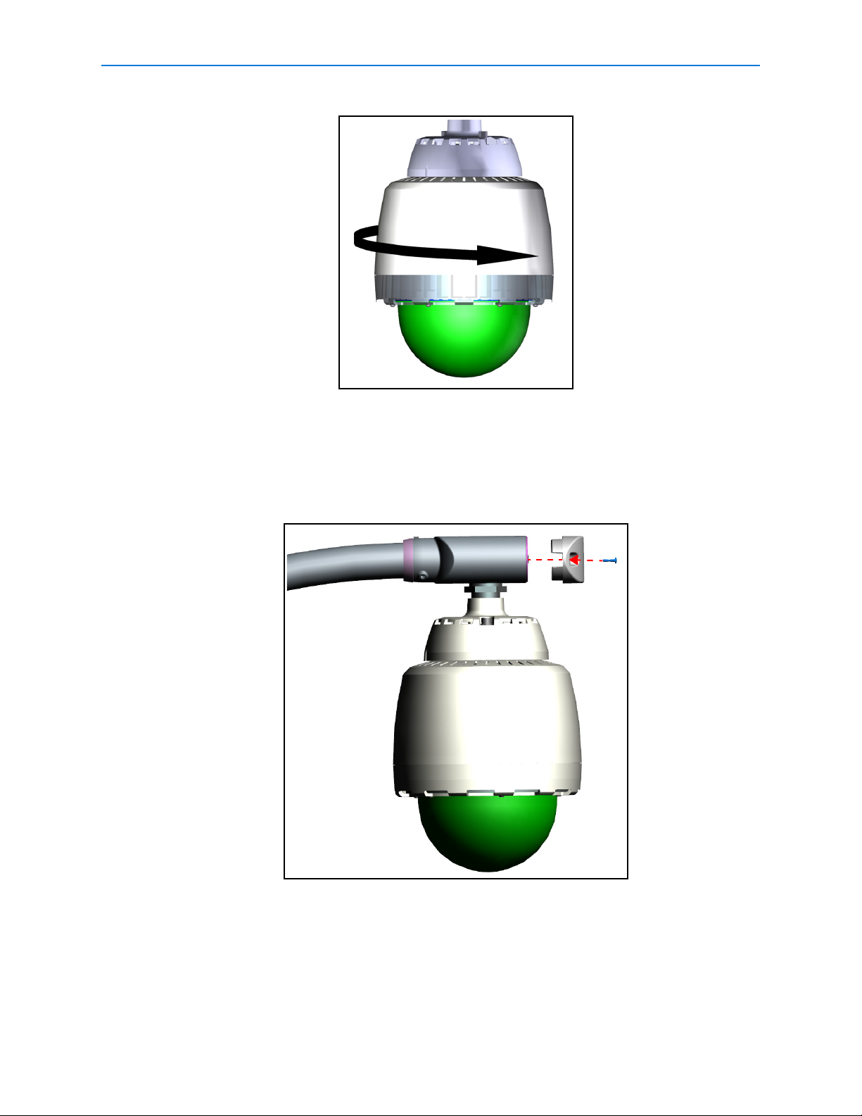
18 Maintain upward pressure and rotate the camera housing clockwise to lock into position
as seen in
Figure 18.
Ensure that both bayonet lock pins are fully engaged before removing your hands from the
outdoor camera housing.
12 Quick Reference Guide
Page 17
Illustra Pro PTZ Outdoor Housing
Figure 18
The camera housing is now supported.
19 Tighten the two M8 screws highlighted in Figure 3 in the pendant adapter using the HEX
L-Key Tool, to fully secure the outdoor camera housing.
20 Push any excess cable into the EndCap and replace the access cover as seen in Figure
19.
Figure 19
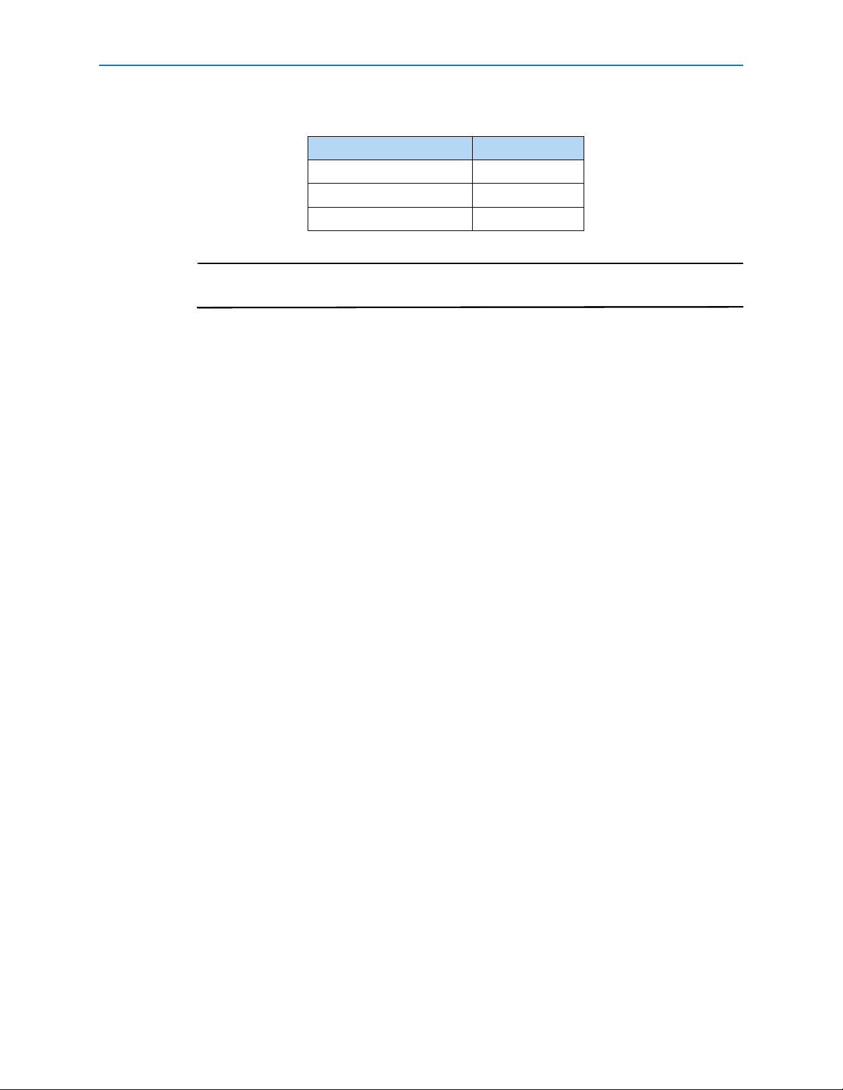
21 Terminate the power cable using the ADSPOT (recommended) power supply. Refer to
8200-2573-29 ADSPOT Single-Position Outdoor Transformer Installation Guide for details
on connecting the cables.
13
Page 18
Illustra Pro PTZ Outdoor Housing
Note
If you are using another power source please refer to the documentation supplied with the
unit.
3 Wire AC Supply Color
24Vac Black
- Yellow/Green
24Vac Black
When using the ADSPOT power supply, ensure that the center tap jumper on the
secondary side between 12v and GND has been removed.
22 Terminate the alarms and audio cables using the Breakout Box. Refer to 8200-0999-05xx
A0 Breakout Box Quick Reference Guide for details on connecting the cables.
14 Quick Reference Guide
Page 19
Illustra Pro PTZ Outdoor Housing
Note
Specifications
Electrical (combined dome and housing)
• Input Voltage 22 to 30Vac, 50/60 Hz
NEC Class 2/Certified Limited Power Source
Maximum operation current 2.5A. Certified Limited Power Source
Environmental
• Operating Temperature –40°C to 50°C
(–40°F to 122°F)
• Relative Humidity 0 to 95% non-condensing
• Storage Temperature –10°C to 50°C
(14°F to 122°F)
• Wind loading Sustained winds of 240Km/hour (150 miles/hour) when properly installed and
mounted
• Enclosure rating IP66 / NEMA 4
• Suitable for altitudes <3200m
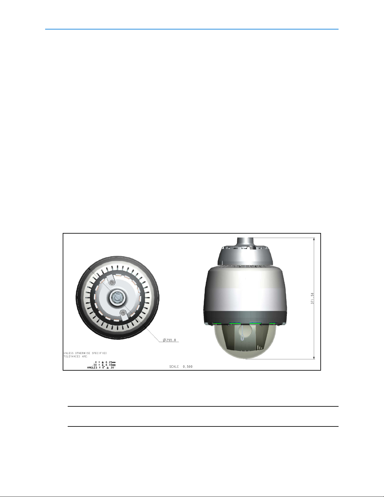
Mechanical Details and Dimensions
Dimensions are in mm
Weight Fully Assembled: 6.45Kg (14.22lbs)
Fully assembled weight is the total weight attached to the mount, this includes the pendant adapter
assembly.
Housing: 2.09Kg (4.61lbs)
Camera: 1.85Kg (4.08lbs)
15
Page 20

Illustra Pro PTZ Outdoor Housing
16 Quick Reference Guide
 Loading...