


 Loading...
Carrera 2000 PC Touch
SALES AGENTS AND SERVICE ORGANISATIONS ......................................................... |
|
1 |
|
SPARE PARTS .......................................................................................................... |
|
|
1 |
INTRODUCTION ......................................................................................................... |
|
|
2 |
WARNINGS FOR USE OF THE INSTRUCTIONS ............................................................ |
|
2 |
|
PURPOSE AND LIMITS OF THE INSTRUCTION AND MAINTENANCE MANUAL |
.............2 |
||
KEEPING OF THE MANUAL ..................................................................................... |
|
|
2 |
UPDATING OF THE MANUAL .................................................................................. |
|
|
2 |
COLLABORATION WITH THE USER ......................................................................... |
|
2 |
|
MACHINE IDENTIFICATION DATA |
............................................................................. |
|
3 |
EC STAMPING AND SAFETY STANDARDS...................................................................... |
|
4 |
|
SAFETY RULES......................................................................................................... |
|
|
5 |
CLOTHING............................................................................................................... |
|
|
7 |
ACCESS TO THE WORKING ZONE.............................................................................. |
|
|
7 |
MACHINE USE DESTINATION.................................................................................... |
|
|
8 |
MACHINE APPLICATION ........................................................................................... |
|
|
8 |
VALUATION OF RISKS .............................................................................................. |
|
|
9 |
RISKS LINKED TO THE INSTALLATION SITE OF THE MACHINE................................. |
|
9 |
|
RISKS LINKED TO THE FEATURES OF THE MACHINE ............................................... |
|
9 |
|
RESIDUE RISKS ZONES AND OPERATIONS............................................................... |
|
10 |
|
WARNING SIGNS ................................................................................................... |
|
|
10 |
RESIDUE DANGERS ................................................................................................ |
|
|
11 |
WORKING AND CONTROL ZONES - SAFETY ZONES .................................................. |
|
11 |
|
ENVIRONMENTAL USE CONDITIONS ....................................................................... |
|
12 |
|
NOISE LEVEL ...................................................................................................... |
|
|
12 |
TEMPERATURE AND HUMIDITY ............................................................................ |
|
|
12 |
OPERATIONAL SITE............................................................................................. |
|
|
12 |
ILLUMINATION ................................................................................................... |
|
|
12 |
VIBRATIONS ....................................................................................................... |
|
|
12 |
RESIDUE AND ENVIRONMENTAL CONTAMINATION ............................................... |
|
12 |
|
SAFETY DEVICES ................................................................................................... |
|
|
13 |
MACHINE INSTALLATION .......................................................................................... |
|
|
14 |
INSTALLATION SITE REQUIREMENTS...................................................................... |
|
14 |
|
EXTERNAL INSTALLATION REQUIREMENTS ............................................................. |
|
14 |
|
UNPACKING........................................................................................................... |
|
|
14 |
MACHINE UNPACKING AND POSITIONING ............................................................... |
|
14 |
|
LEVELLING ............................................................................................................ |
|
|
17 |
ATTACHMENT OF INFEED CONVEYOR ..................................................................... |
|
18 |
|
© Copyright ILAPAK Italia S.p.A. |
Ed 1 Rev 06 - June 2005 |
User manual –- 1 |
|

Carrera 2000 PC Touch |
|
|
ELECTRICAL SYSTEM CONNECTION ........................................................................ |
20 |
|
EARTHING............................................................................................................. |
|
20 |
PNEUMATIC SYSTEM (OPTIONAL) |
........................................................................... |
21 |
COOLANT INSTALLATION CONNECTION (OPTIONAL) ............................................... |
21 |
|
CLEANING ............................................................................................................. |
|
21 |
MACHINE DEMOLITION............................................................................................. |
|
22 |
MACHINE CONTROLS ................................................................................................ |
|
23 |
PUSH BUTTONS AND OTHER ELECTRO-MECHANICAL DEVICES ................................. |
23 |
|
SIGNAL LAMPS....................................................................................................... |
|
25 |
USER INTERFACE...................................................................................................... |
|
26 |
DISPLAY................................................................................................................ |
|
26 |
OPERATIVE KEYS ................................................................................................... |
|
28 |
MULTIFUNCTIONAL KEYBOARD............................................................................... |
|
29 |
RECALL KEYS......................................................................................................... |
|
30 |
HELP ON LINE ......................................................................................... |
|
30 |
PRELIMINARY OPERATION ........................................................................................ |
|
31 |
LANGUAGE SELECTION........................................................................................... |
|
31 |
USER PASSWORD................................................................................................... |
|
33 |
ENTERING THE PASSWORD .................................................................................... |
|
34 |
DEACTIVATION OF THE PASSWORD........................................................................ |
36 |
|
MODIFICATION OF PASSWORD “OPERATOR”........................................................... |
37 |
|
OPERATION CYCLE START......................................................................................... |
|
39 |
BASE PAGE ............................................................................................................ |
|
40 |
CREATION OF A NEW PRODUCT ............................................................................. |
|
41 |
CREATION OF A NEW DATABASE ......................................................................... |
42 |
|
MECHANICAL MACHINE ADJUSTMENTS ...................................................................... |
45 |
|
DETERMINING THE STEP OF THE PRODUCT FEED LUGS........................................... |
45 |
|
INSERTING THE INFEED LUGS ................................................................................ |
|
46 |
FIXED FOLDING BOX ........................................................................................... |
|
47 |
ADJUSTABLE FOLDING BOX (OPTIONAL) .............................................................. |
48 |
|
ADJUSTABLE FOLDING BOX (OPTIONAL) .............................................................. |
48 |
|
ADJUSTING PRODUCT GUIDES............................................................................. |
|
49 |
DETERMINING THE WIDTH OF THE REEL ................................................................ |
50 |
|
MOUNTING FILM REELS ......................................................................................... |
|
50 |
INSERTING FILM.................................................................................................... |
|
51 |
© Copyright ILAPAK Italia S.p.A. |
Ed 1 Rev 06 - June 2005 |
User manual –- 2 |
Carrera 2000 PC Touch |
|
|
ADJUSTING THE MECHANICAL ARM ........................................................................ |
52 |
|
ADJUSTING THE FILM REEL BRAKE ......................................................................... |
53 |
|
JAW HEIGHT ADJUSTMENT..................................................................................... |
|
54 |
VERSION “CARRERA 2000 PC 400” ....................................................................... |
54 |
|
JAW HEIGHT SELECTION ..................................................................................... |
|
54 |
VERSION “CARRERA 2000 PC 250” ....................................................................... |
55 |
|
MOUNTING THE INTERCHANGEABLE PRODUCT SUPPORT ........................................ |
56 |
|
ENTERING PRODUCT DIMENSIONS AND ADJUSTMENTS.............................................. |
57 |
|
ENTERING THE OPERATING PARAMETERS OF THE MACHINE.................................... |
61 |
|
“TEMPERATURE” PAGES ......................................................................................... |
|
62 |
“TEMPERATURES ACCORDING TO THE MACHINE SPEED ............................ |
64 |
|
PAGE “PRODUCTION RELATED DATA” ..................................................................... |
66 |
|
OFF SET PARAMETER |
........................................................................... |
68 |
“ACCESSORIES” PAGE ............................................................................................ |
|
69 |
DESCRIPTION OF PARAMETERS |
.................... |
70 |
ACCESSOIRES PAGE: PRINTER/GUSSET/CARDBOARD CUTTER ............................... |
71 |
|
PRINTER ........................................................................................... |
|
71 |
GUSSET ............................................................................................ |
|
71 |
CARDBOARD CUTTER |
..................................................................... |
72 |
INDEPENDENT CUT |
......................................................................... |
72 |
ACCESSOIRES PAGE: LABEL APPLICATOR/SPRAY................................................... |
73 |
|
LABEL APPLICATOR ............................................................................ |
|
73 |
SPRAY ............................................................................................... |
|
73 |
VARIOUS ACCESSORY PAGES............................................................................... |
|
74 |
"USER CAMS" PAGE .................................................................................... |
|
75 |
© Copyright ILAPAK Italia S.p.A. |
Ed 1 Rev 06 - June 2005 |
User manual –- 3 |
Carrera 2000 PC Touch |
|
|
PAGE “FUNCTIONS” .................................................................................... |
|
78 |
PRE-PRODUCTION .................................................................................................... |
|
81 |
VERIFICATION OF SETTINGS AND ADJUSTMENTS.................................................... |
81 |
|
ADDITIONAL TESTING PROCEDURES WITH REGISTERED PRINT ......................... |
82 |
|
TEST RUN.............................................................................................................. |
|
85 |
ADVANCED FUNCTIONS: MISPLACE - NO PRODUCT NO BAG..................................... |
87 |
|
PRODUCT SAFETY SYSTEM (MISPLACE) ..................................................... |
87 |
|
INTRODUCTION OF THE FUNCTION “PRODUCT SAFETY” ...................................... |
88 |
|
ENTERING PARAMETERS ..................................................................................... |
|
89 |
ACTIVATION OF THE FUNCTION “PRODUCT SAFETY” (MISPLACE).......................... |
91 |
|
“NO PRODUCT / NO BAG” |
................................................................. |
92 |
NOTES FOR THE CORRECT CALIBRATION OF THE PHOTOCELL. ............................. |
92 |
|
CONDITIONS FOR THE CORRECT FUNCTIONING ................................................ |
92 |
|
OPERATING RULES ........................................................................................... |
|
92 |
ACTIVATING THE “NO PRODUCT / NO BAG” FUNCTION ...................................... |
93 |
|
AVAILABLE INSTRUMENTS ................................................................................ |
|
93 |
OPERATING ..................................................................................................... |
|
94 |
DATA NEEDED FOR THE AUTOMATIC CALCULATION........................................... |
94 |
|
HOW TO CHANGE THE PRODUCT STOP POSITION.............................................. |
96 |
|
USE OF THE FILM ADVANCE.............................................................................. |
|
96 |
FORCING OF THE FILM STOP CYCLE AT THE CUT-OFF ........................................ |
97 |
|
SAVING PARAMETER VALUES |
...................................................................... |
98 |
PRODUCTION ......................................................................................................... |
|
100 |
SIZE CHANGE ........................................................................................... |
|
102 |
STATISTICS .............................................................................................. |
|
104 |
PRODUCTS LIST MANAGEMENT ............................................................................... |
|
105 |
DELETION OF A PRODUCT |
........................................................................ |
105 |
COPYING A PRODUCT ............................................................................... |
|
107 |
© Copyright ILAPAK Italia S.p.A. |
Ed 1 Rev 06 - June 2005 |
User manual –- 4 |

Carrera 2000 PC Touch |
|
|
CORRECTING/CHANGING A PRODUCT NAME ......................................................... |
109 |
|
DIAGNOSTIC .......................................................................................................... |
|
111 |
“DIAGNOSTIC” PAGE. ........................................................................................... |
|
111 |
“INFEED AXIS” PAGE ............................................................................................ |
|
112 |
“FILM AXIS” PAGE ................................................................................................ |
|
113 |
“ROLLER AXIS” PAGE............................................................................................ |
|
114 |
“JAW AXIS” PAGE................................................................................................. |
|
115 |
“DISCHARGE BELT” PAGE (OPTIONAL). ................................................................. |
116 |
|
“AUTOMATIC FEEDER” (OPTIONAL) ...................................................................... |
117 |
|
“TEMPERATURE” PAGE ......................................................................................... |
|
118 |
“I/O STANDARD” PAGE......................................................................................... |
|
119 |
“DIGITAL INPUT” PAGE ........................................................................................ |
|
120 |
“DIGITAL OUTPUT” PAGE ..................................................................................... |
|
121 |
“ANALOG INPUT/OUTPUT” PAGE ........................................................................... |
|
122 |
“ALARM LIST” PAGE ............................................................................................. |
|
123 |
TROUBLESHOOTING ............................................................................................... |
|
124 |
MACHINE MALFUNCTION DURING OPERATION ...................................................... |
124 |
|
ERROR MESSAGES ............................................................................................... |
|
139 |
MESSAGGE .......................................................................................................... |
|
139 |
PROBLABLE CAUSE / REMEDY ............................................................................ |
|
139 |
MAINTENANCE ....................................................................................................... |
|
142 |
GENERAL............................................................................................................. |
|
142 |
SAFETY CONDITION............................................................................................. |
|
142 |
PUTTING IN MAINTENANCE CONDITION ............................................................... |
143 |
|
PERIODICAL MAINTENANCE ................................................................................. |
|
143 |
MACHINE............................................................................................................. |
|
144 |
MACHINE MAINTENANCE...................................................................................... |
|
146 |
FRAME CLEANING AND MAIN COMPONENTS ....................................................... |
146 |
|
INFEED CONVEYOR ........................................................................................... |
|
146 |
MACHINE BODY ................................................................................................ |
|
146 |
LONGITUDINAL SEALING AND PROPELLING ROLLERS ......................................... |
147 |
|
JAWS................................................................................................................ |
|
147 |
DISCHARGE CONVEYOR BELT ............................................................................ |
|
147 |
JAW AND ROLLER HEATER ROTARY COLLECTORS ............................................... |
147 |
|
LEVELLING CHECK............................................................................................. |
|
147 |
MECHANICAL PARTS MAINTENANCE...................................................................... |
148 |
|
BOLTS AND NUTS TIGHTENING CHECK .............................................................. |
148 |
|
WEAR AND TEAR CHECK AND REEL BRAKE OPERATION: ..................................... |
148 |
|
© Copyright ILAPAK Italia S.p.A. |
Ed 1 Rev 06 - June 2005 |
User manual –- 5 |

Carrera 2000 PC Touch |
|
LUBRICATION OF DRIVE CHAINS ....................................................................... |
148 |
CHECK OF TRANSMISSION BELT TENSION.......................................................... |
148 |
CHECK OF MOTOR BELT .................................................................................... |
148 |
MAINTENANCE MOTOR – ADAPTORS – VARIATOR ................................................. |
149 |
CHECK AND OIL REPLACEMENT.......................................................................... |
149 |
MAINTENANCE OF SAFETY DEVICES ..................................................................... |
150 |
EFFICIENCY CHECK OF THE EMERGENCY STOP BUTTON ..................................... |
150 |
EFFICIENCY CHECK OF THE SAFETY SWITCHES .................................................. |
150 |
ELECTRICAL INSTALLATION MAINTENANCE........................................................... |
151 |
CABLES FIXING CHECK ...................................................................................... |
151 |
MAINTENANCE PUSHBUTTONS, CONTROL SELECTORS AND INDICATORS............. |
151 |
PNEUMATIC INSTALLATION MAINTENANCE (OPTIONAL) ........................................ |
152 |
CONDENSATION DRAINAGE AND PRESSURE REGULATOR FILTER CLEANING ........ |
152 |
LUBRICATING OIL LEVEL CHECK ........................................................................ |
152 |
EFFICIENCY CHECK OF THE PNEUMATIC INSTALLATION COMPONENTS................ |
154 |
COOLANT INSTALLATION MAINTENANCE (OPTIONAL) ........................................... |
155 |
WATER CIRCULATION CHECK ............................................................................ |
155 |
COOLANT CIRCUITS PIPING CHECK.................................................................... |
155 |
AIR CLEANING FILTER REPLACEMENT ................................................................... |
156 |
REPLACEMENT OF COMPONENTS .......................................................................... |
157 |
REPLACEMENT OF UPPER JAW KNIFE ................................................................. |
157 |
ADJUSTMENT OF UPPER JAW KNIFE................................................................... |
157 |
REPLACEMENT OF LOWER JAW ANVIL ................................................................ |
157 |
REPLACEMENT OF HEATING RESISTANCES CARBON BRUSHES............................. |
159 |
JAW HEATER.................................................................................................. |
159 |
SEALING ROLLER HEATERS............................................................................. |
159 |
REPLACEMENT OF HEATER RESISTANCES........................................................... |
161 |
UPPER JAW HEATER ....................................................................................... |
161 |
LOWER JAW HEATER ...................................................................................... |
161 |
SEALING ROLLER HEATERS................................................................................ |
162 |
REPLACEMENT OF TEMPERATURE PROBES ......................................................... |
162 |
UPPER AND LOWER JAW TEMPERATURE PROBE ............................................... |
162 |
SEALING ROLLER TEMPERATURE PROBE ............................................................ |
163 |
© Copyright ILAPAK Italia S.p.A. |
Ed 1 Rev 06 - June 2005 |
User manual –- 6 |

Carrera 2000 PC Touch
SALES AGENTS AND SERVICE ORGANISATIONS
The Sales Agent and Service Organisation in your area is:
TO BE FILLED IN BY THE AGENT OR AREA REPRESENTATIVE
The machine subject of this publication was designed by ILAPAK S.p.A. (Nova Milanese; Milano; Italy), which is a company of the ILAPAK group.
ILAPAK ITALIA S.p.A. puts its proper Assistance Service at disposition of the customers in order to solve whatever problem regarding the use and the maintenance of their machines.
The customers can signal their requests to the related commercial ILAPAK companies.
SPARE PARTS
It is recommended to use exclusively original spare parts.
The requests for spare parts should be made at the related commercial ILAPAK Company, observing the standards contained in the catalogue of the spare parts and nominating always the type and serial number of the machine.
© Copyright ILAPAK Italia S.p.a |
Ed 1 Rev 06 - June 2005 |
PAGE -1 |

Carrera 2000 PC Touch
INTRODUCTION
WARNINGS FOR USE OF THE INSTRUCTIONS
PURPOSE AND LIMITS OF THE INSTRUCTION AND MAINTENANCE MANUAL
This manual is destined to all the operators in charge of the use, maintenance and surveillance of the machine during its working life.
The purpose of the manual is to supply the information regarding:
-The technical features of the machine
-The preparation of the working site regarding the environmental characteristics and the feeding sources
-The accident prevention standards, use and calibration of the safety devices
-The use of the machine as provided in the project
-The ordinary and extraordinary maintenance
-The availability of the spare parts
The manual cannot replace the specific preparation, which the operators should have carried out previously on equal appliances or who will be accompanied on this machine by already skilled staff.
KEEPING OF THE MANUAL
The use and maintenance manual is considered integral part of the machine and should be kept for future reference till the final dismantling of the machine.
The manual should always be available for consultation and should be kept with care; in case of damaging which compromises also partially the consultation, the user has to ask a new exemplar to the constructor.
UPDATING OF THE MANUAL
This manual has been prepared at the same time with the realization of the referred machine and cannot be considered inadequate only because successively updated (also for similar machines) according to new experiences.
ILAPAK ITALIA S.p.A. has the right to modify together with its production also the related manuals, without the obligation to update the previous supplied ones. Possible integrations sent to the users, under the form of “UPDATING”, have to be kept together with the manual.
COLLABORATION WITH THE USER
ILAPAK ITALIA S.p.A. is at disposition of its customer to supply further information regarding the use and the maintenance of their machines as well as considering improving proposals for the manual in order to make them always more suitable to the requirements of the customers.
© Copyright ILAPAK Italia S.p.a |
Ed 1 Rev 06 - June 2005 |
PAGE -2 |
Carrera 2000 PC Touch
MACHINE IDENTIFICATION DATA
The main identification data of the machine are printed on the proper plate with the EC marking installed outside the machine.
The plate notes the following data:
-Name of manufacturer and his address
-Type of machine
-Serial number
-Construction date
-Feeding voltage
-Absorbed power
-EC marking
Another plate, fixed inside the electrical panel, notes furthermore the values in relation to the electrical supply
-Serial number of the electrical panel
-Nominal voltage
-Frequency
-Number of phases
-Frequency
-Full load current
-Number of the wiring diagram
-Short-circuit interruption power
NOTE In case of a technical assistance request or an order of the spare parts, nominate always the type and serial number of the machine a/o the data in relation to the electrical supply.
Machine identification
© Copyright ILAPAK Italia S.p.a |
Ed 1 Rev 06 - June 2005 |
PAGE -3 |

Carrera 2000 PC Touch
EC STAMPING AND SAFETY STANDARDS
The machine bears the EC stamp indicating conformity with Directive 89/392/EEC, and subsequent modifications, of the European Community Council.
NOTE: The stamp is affixed to the machine nameplate.
The original copy of “EEC Statement of conformance” is handed over to the customer at the time of machine delivery.
This document shall be carefully kept by the Customer, and produced upon request by the concerned Authorities.
The “EEC Statement of Conformance” is to be considered an integral part of the machine, and shall be transferred to the new owner whenever the machine is re-sold.
© Copyright ILAPAK Italia S.p.a |
Ed 1 Rev 06 - June 2005 |
PAGE -4 |
Carrera 2000 PC Touch
SAFETY RULES
The following safety rules should be observed during installation, operation and maintenance of the machine. Lack of compliance with the following rules may result in impaired effectiveness of the machine safety features.
The staff in charge of the use, the maintenance and the surveillance of the machine should be instructed by the employer regarding the accident risks, the safety devices installed on the machine and the general accident prevention rules, provided by the international norms and the laws of the country where the machine is installed.
ILAPAK denies any liability for machine damage or injuries to the operator third parties arising from the lack of compliance with the safety rules listed hereafter.
•MACHINE DISPLACEMENT DURING INSTALLATION MUST BE CARRIED OUT ONLY BY SPECIALISED PERSONNEL, AND BY USE OF SUITABLE LIFTING AND TRANSPORTATION EQUIPMENT.
•MAKE SURE THAT ALL NECESSARY PRECAUTIONS ARE TAKEN DURING LIFTING OR TRANSPORTATION OF THE MACHINE, AND THAT ALL THE INSTRUCTIONS CONTAINED IN THIS MANUAL ARE CAREFULLY ADHERED TO.
• MACHINE CONNECTION TO THE ELECTRICAL POWER MEANS SHALL BE CARRIED OUT ONLY BY SKILLED PERSONNEL.
•  BEFORE CONNECTING MACHINE TO THE ELECTRICAL POWER
MAINS, MAKE SURE THAT THE MAINS ELECTRICAL CHARACTERISTICS CORRESPOND TO THOSE SPECIFIED ON THE MACHINE NAMEPLATE. ALSO, MAKE SURE THAT THE MAINS IS PROVIDE WITH A SUITABLE GROUND WIRE, AND THAT THE VOLTAGE MEASURED ON THE NEUTRAL WIRE IS ZERO.
• |
THE WIRES OF THE ELECTRICAL CONNECTION CABLE SHALL HAVE |
|
A MINIMUM CROSS-SECTION OF 4 SQUARE MM. |
•THE MACHINE SHALL BE OPERATED ONLY BY SKILLED AND AUTHORISED PERSONNEL.
•THE MACHINE OPERATOR SHALL MAKE SURE THAT ALL THE INSTRUCTIONS GIVEN IN THIS MANUAL ARE CORRECTLY FOLLOWED.
• JAW MOTION REPRESENTS THE GREATEST DANGER FOR THE OPERATOR WHEN THE MACHINE IS RUNNING. IN ORDER TO PROTECT THE OPERATOR, THE MACHINE IS PROVIDED WITH A SAFETY DEVICE THAT PERMITS MACHINE OPERATION ONLY WHEN THE PROTECTION GUARDING ARE CLOSED.
© Copyright ILAPAK Italia S.p.a |
Ed 1 Rev 06 - June 2005 |
PAGE -5 |

Carrera 2000 PC Touch
• |
IN CASE OF MAINTENANCE OR REPAIR ACTIONS REQUIRING THAT |
|
THE MACHINE OPERATES WITH PROTECTION GUARDING OPEN (SAFETY |
|
DEVICE CUT OUT), PROCEED WITH EXTREME CAUTION TO PREVENT |
|
HAZARDS OR INJURIES TO THE OPERATOR. |
• |
IN CASE OF DANGER FOR THE OPERATOR, OR WHENEVER IT IS |
|
NECESSARY TO IMMEDIATELY STOP THE MACHINE, PRESS THE RED |
|
EMERGENCY STOP PUSH-BUTTON. THIS BUTTON STOPS THE MACHINE AT |
|
ONCE IRRESPECTIVE OF THE KIND OF WORKING OPERATIONS IN |
|
PROGRESS. |
•THE USER IS RESPONSIBLE FOR THE OPERATIONAL SAFETY OF ANY AUXILIARY EQUIPMENT NOT SUPPLIED BY ILAPAK.
•ANY ACTION ON THE MACHINE WHICH MAY INTERFERE WITH THE SAFETY DEVICES IS CARRIED OUT AT THE OPERATOR’S RISK.
•  IN CASE OF MAINTENANCE OR REPAIR ACTIONS REQUIRING
OPENING OR DISABLING OF PROTECTIONS, PROCEED WITH THE UTMOST CARE AND IMPLEMENT ALL THE APPLICABLE SAFETY MEASURES. THESE ACTIONS SHALL BE CARRIED OUT ONLY BY AUTHORISED PERSONNEL.
• MAKE SURE THAT THE ELECTRICAL POWER SUPPLY IS DISCONNECTED AND THE PNEUMATIC SYSTEM IS DISCHARGED BEFORE CARRYING OUT ANY ADJUSTMENT/CALIBRATION OF THE MACHINE.
•  MAKE SURE THAT THE MACHINE IS DISCONNECTED FROM THE
ELECTRICAL POWER MAINS BEFORE CARRYING OUT ANY CLEANING OR LUBRICATION OPERATION. POSITIVELY AVOID DIRECTING WATER JETS ON THE MACHINE, INSIDE IT, ON THE CONTROL PANEL, AND ABOVE ALL INSIDE THE ELECTRICAL CABINET.
•DO NOT EMBODY MODIFICATIONS IN THE MACHINE WITHOUT PRIOR AUTHORISATION BY ILAPAK.
•ANY MODIFICATION SHALL BE EMBODIED BY ILAPAK AUTHORISED PERSONNEL ONLY, AND RECORDED IN THE APPLICABLE TECHNICAL DOCUMENTATION. ANY TAMPERING OF THE MACHINE, OR MODIFICATION PERFORMED BY THIRD PARTIES VOIDS ANY RESPONSIBILITY OF ILAPAK IN CASE OF MALFUNCTION OR INJURY TO THE OPERATOR.
© Copyright ILAPAK Italia S.p.a |
Ed 1 Rev 06 - June 2005 |
PAGE -6 |

Carrera 2000 PC Touch
CLOTHING
The clothing of the operator or the person, who carries out maintenance on the machine should be according to the legal safety rules in the country of application. In general, the operator should wear accident prevention shoes, and it is forbidden to wear moccasins, clogs, slippers or any kind of footwear that could compromise the mobility of the person. Use proper thermo-protective fireproof gloves when working in areas, which are characterised by heat emission.
NOTE : When working on the machine, don’t wear bracelets, watches, rings or chains which can dangle or hinder movements. Pay maximum attention, when working near moving parts of the machine, that the proper clothing is suitable and avoid hitching up with these devices (sleeves, shirt tails, hair, etc.)
ACCESS TO THE WORKING ZONE
The working area should never be occupied so that nothing interferes with the freely movement of the operator. The immediate access to the machine from the staff in charge should be guaranteed in emergency cases.
It is forbidden to have access to the working area to people who are not directly in charge with the operation of the machine. This should be signalled with proper signs.
ATTENTON During the maintenance operations, in particular way when you work with protections or disconnected safety devices, it is necessary to pay the maximum attention that the working area is not accessible to people, who are not directly in charge with these operations. At the end of the maintenance interventions verify that no used tool remains inside the accident prevention guards or inside the working area.
© Copyright ILAPAK Italia S.p.a |
Ed 1 Rev 06 - June 2005 |
PAGE -7 |

Carrera 2000 PC Touch
MACHINE USE DESTINATION
MACHINE APPLICATION
THE WRAPPING MACHINE MODEL CARRERA 2000 PC IS DESIGNED TO WRAP FOOD PRODUCTS AND INERT MATERIALS.
IT MAY NOT BE USED TO WRAP PRODUCTS WHICH MIGHT REPRESENT A SAFETY HAZARD FOR THE OPERATOR OR SEVERELY DAMAGE THE MACHINE
• POSITIVELY DO NOT WRAP GAS-CONTAINING BOTTLES, CONTAINERS OR JELLIES OF THE FOLLOWING MATERIALS: GUN POWDER OR SIMILAR MATERIALS, FLAMMABLE FLUIDS, GLUES, SOLVENTS, ETHER, ALCOHOL, GASOLINE, CATALYST AND CORROSIVE ACIDS, ETC.
• POSITIVELY DO NOT WRAP ANY CHEMICALS OR OTHER MATERIALS WHICH MAY REACT AT THE SEALING TEMPERATURES AND RELEASE POISONOUS, FLAMMABLE OR EXPLOSIVES GASES, ETC.
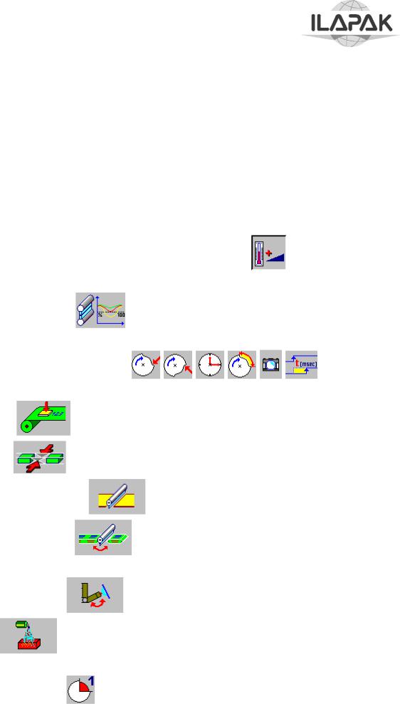
•  WHEN THE OPERATION OF THE MOTORISED PRODUCT SUPPORT
DEVICE HAS BEEN ACTIVATED (FUNCTIONAL KEY  ) AVOID THAT THE MAXIMUM PRODUCTION SPEED EXCEEDS 90 PIECES PER MINUTE.
THE MACHINE SHOULD BE USED FOR THE WRAPPING WITH EXACTLY DEFINED CHARACTERISTICS AND WITHIN THE LIMITS ESTABLISHED BY THE SUPPLYING CONTRACT, DRAWN BETWEEN THE PURCHASER AND THE CONSTRUCTOR. THE USE OF THE MACHINE TO OBTAIN HIGHER PRODUCTION VALUES OR DIFFERENT FROM THE ESTABLISHED ONE IS CONSIDERED AS AN IMPROPER USE AND THE CONSTRUCTOR DENIES EVERY LIABILITY FOR DAMAGES CAUSED TO THINGS OR PEOPLE AND DOESN’T ACCEPT ANY KIND OF GUARANTEE ON THE MACHINE.
ILAPAK DENIES ANY LIABILITY DERIVING FROM IMPROPER USE OF THE MACHINE.
© Copyright ILAPAK Italia S.p.a |
Ed 1 Rev 06 - June 2005 |
PAGE -8 |

Carrera 2000 PC Touch
VALUATION OF RISKS
Risks linked to the installation site of the machine
On the installation site of the machine there can be some risky situations, which could compromise the correct operation.
FLOOR
The surfaces where the machine is placed on should guarantee during time the correct placing and levelling; for example some asphalt floor under high temperatures condition and in presence of soluble liquids can present an accelerated wear and tear with possible formation of holes corresponding to the supporting points and therefore making the machine position unstable.
TEMPERATURE
The established environmental temperature should be guaranteed (from 2 to 35 °C); high temperature peaks could cause machine operation problems (for example cooling difficulty of the motors).
POLLUTING MATERIAL
The potential damage coming from the use in the working area with polluted material should be preventively valuated; for example:
DUST which could accelerate the wear and tear of the seals;
PVC which thermal degradation, generating HCl, can cause aggressive emissions of the metal surfaces without proper protections.
MAGNETIC FIELDS,
Determined by the passage of electrical power lines near the electronic appliances installed on the machine. They can cause disturbances and malfunctioning.
WARNING The user should assure the suitability of the installation place of the machine, in order to save its integrity during time.
RISKS LINKED TO THE FEATURES OF THE MACHINE
According to the EEC 89/392 standards, all the areas of the machine characterised by intrinsic with the working process or with the structure of the machine have been analysed. The most suitable measurements have been taken to reduce, as well as to eliminate possible risks to people in charge, equipping the machine with a series of standard protections, fixed and movable, which stop the access to the dangerous areas during the working. However, the best safeguarding for the operator’s safety is that the operator himself pays attention and has a good sense and that the greatest experience during time using the machine, can improve the safety margins during the operation.
© Copyright ILAPAK Italia S.p.a |
Ed 1 Rev 06 - June 2005 |
PAGE -9 |

Carrera 2000 PC Touch
RESIDUE RISKS ZONES AND OPERATIONS
The areas of the machine or the procedures, which, even with suitable safety measurements present a high danger degree are defined residue risks, for example the presence of high voltage, high temperature or moving parts. All the areas with residue risks have been marked with proper name plates according to the ISO standards;
WARNING SIGNS
In compliance with the EC regulations, and in order to highlight the machine areas requiring special operator’s attention, or involving particular hazards for operator safety, the following warning signs are used.
|
|
|
|
|
|
|
|
|
|
|
|
|
|
|
|
|
|
|
|
|
|
|
|
|
|
|
|
|
|
|
|
|
|
|
|
|
|
|
|
|
|
|
|
|
|
|
|
|
|
|
|
|
|
|
|
|
|
|
|
|
|
|
|
|
|
|
|
|
|
|
|
|
|
|
|
|
|
|
|
|
|
|
|
|
|
|
|
|
|
|
|
|
|
|
|
|
|
|
|
|
|
|
|
|
|
|
|
|
|
|
|
|
|
|
|
|
|
MOVING GEARS |
|
LIVE LINE |
|
|
|
|
|
|
|
|
|
|
|
|
|
|
|
|
|
|
|
|
|
|
|
|
|
|
|
|
|
|
|
|
|
|
|
|
|
|
|
|
|
|
|
|
|
|
|
|
|
|
|
|
|
|
|
|
|
|
|
|
|
|
|
|
|
|
|
|
|
|
|
|
|
|
|
|
|
|
|
|
|
|
HOT SPOT
|
|
|
|
|
|
|
|
|
|
|
|
|
|
|
|
|
|
|
|
|
CUT/SEVER HAND AND |
|
PUT TENSION OFF |
FINGERS |
BEFORE WORKING |
|
|
|
INSIDE |
© Copyright ILAPAK Italia S.p.a |
Ed 1 Rev 06 - June 2005 |
PAGE -10 |

Carrera 2000 PC Touch
RESIDUE DANGERS
• |
|
INFEED CONVEYOR END |
|
||
|
There is the danger that your hands may caught and crushed where |
|
|
product lugs return upward at the end of the infeed conveyor. Therefore, |
|
|
avoid working in this area, and pay much attention if working there cannot |
|
|
be avoided. |
|
• |
|
ADJUSTMENT OF PRODUCT GUIDES |
|
||
|
||
|
Adjustment of the product guides shall be such as there is a gap of less |
|
|
than 5 millimeters or of more than 25 millimeters between the guide and |
|
|
the pusher. |
|
|
If the product to be wrapped requires that the distance between the guide |
|
|
and the pusher is set a value between 5 and 25 mm, pay much attention as |
|
|
you run the risk that your hands are caught between the guide and the |
|
|
pusher. |
|
• |
|
CONVEYOR AREA |
|
||
|
||
|
Lug overturning creates a serious danger for your hands. They may be |
|
|
crushed. Pay much attention when working in this area. |
|
• |
|
LOADING OF FILM REELS |
|
The loading of reels weighing between 18 and 36 kg shall be made by two |
|
|
people. |
|
|
Load the heavier reels by use of a suitable equipment (not supplied with |
|
|
the machine). |
|
WORKING AND CONTROL ZONES - SAFETY ZONES
The description of the working and control areas, is indicated in the layout included with the statement of conformance.
© Copyright ILAPAK Italia S.p.a |
Ed 1 Rev 06 - June 2005 |
PAGE -11 |

Carrera 2000 PC Touch
ENVIRONMENTAL USE CONDITIONS
NOISE LEVEL
The noise emitted by the wrapping machine during operation is 73 dB as resulting from the measurements carried out by using a sample machine.
TEMPERATURE AND HUMIDITY
The machine can be used in rooms with room temperature included between 2 and 35 °C and with a related humidity lower than 80 %.
OPERATIONAL SITE
The machine should be used protected against atmospheric conditions (rain, hail, snow, fog, etc.). Should the machine be used in corrosive sites, it is necessary to intervene on the modality and the maintenance periods, adapting it in order to avoid an excessive wear and tear of the components.
The use of the machine under explosive or partially explosive conditions isn’t provided, therefore it is forbidden to use it under these conditions.
ILLUMINATION
The room where the machine is placed should be illuminated in such a way to individuate easily the buttons and the devices for the control and the emergency stop.
The illumination should allow carrying out under safety condition the ordinary maintenance operations; the user should carry out these interventions according to the legal rules regarding the modality of the illumination.
VIBRATIONS
Under normal use conditions, following the indications from this manual, the vibrations may not cause danger situations. In case of anomalous vibrations, stop immediately the machine and get in touch with the assistance service.
RESIDUE AND ENVIRONMENTAL CONTAMINATION
If the used material for the production is elaborated according to the recommendations of the constructor, there won’t be noxious substances, as regards the EN 626-1 standards. In case of using toxic or noxious plastic materials, the user has to install proper fume aspiration hoods and the training of the operators for a correct treatment of these materials. The user should observe the legal standards and community rules also for the treatment and the lubrications used on the machine.
© Copyright ILAPAK Italia S.p.a |
Ed 1 Rev 06 - June 2005 |
PAGE -12 |

Carrera 2000 PC Touch
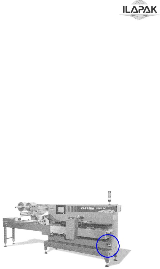
SAFETY DEVICES
The safety devices fitted to the machine are shown in the following picture.
When the safety guards are opened while the machine is in operation, switches stops the main motor and cuts off the power supply.
When pressed, emergency stop buttons interrupt machine operation and cut off the power supply.
Isolator switch is a safety device that cuts off electrical power supply to all machine components when the door of the electrical cabinet is opened.
© Copyright ILAPAK Italia S.p.a |
Ed 1 Rev 06 - June 2005 |
PAGE -13 |

Carrera 2000 PC Touch
MACHINE INSTALLATION
INSTALLATION SITE REQUIREMENTS
The machine should be installed on a supporting floor that can bear the weight of the machine on the several supporting points, without a decline during time; furthermore the floors should be on spirit level, non-slipping and shouldn’t present roughness
The installation site should allow the operator to go around the machine without any hindrances and to carry out easily the normal working operations and service operations (maintenance and interventions on the machine). Furthermore it is extremely important, that the protection guards and the doors of the electrical power boards can be opened without hindrance and in a complete way. For this purpose the minimum distance according to the building walls or to a possible hindrance should be about 2 meters.
EXTERNAL INSTALLATION REQUIREMENTS
The installation site should be prepared for the connection of the electrical installation, the earthing, the pneumatic installation and possible coolant installation of the machine to the outside net. The electrical and earthing installation of the installation site should be realized according to the standards.
UNPACKING
The machine is shipped using packaging or proper protection means according to the used kind of transport; pay particular attention when unpacking in order to avoid damages to people or to the machine and to dismantle the packaging materials according to the legal rules in force in the country where the machine will be used.
At receipt, control visually regarding possible damaging deriving from the shipment or missing parts.
In case of damaging or missing part, get immediately in touch with the forwarding agent.
MACHINE UNPACKING AND POSITIONING
ATTENTION The lifting operations of the parts composing the machine should be carried out by staff in charge of these functions (crane operators, truck drivers, etc.) and with the assistance on the ground by a person in charge with the signalling if the overall dimension of the load doesn’t allow a sufficient visibility; the staff should be equipped with the necessary individual accident prevention protections.
The access to the area where the lifting operations are carried out is forbidden to the staff, who is not in charge with this operation, using the most proper means (barriers, signs, etc.). The capacity of the used lifting means should be suited to the mass to be moved; the movement should be carried out slowly under good illumination conditions and with sufficient free space to work under safety conditions.
For no reason, the staff in charge with the operations is authorized to pass under the load or at its proximity. This is valid also for the staff in charge with the signalling on the ground.
© Copyright ILAPAK Italia S.p.a |
Ed 1 Rev 06 - June 2005 |
PAGE -14 |
Carrera 2000 PC Touch
Carefully follow this procedure when unpacking and positioning the machine:
•Remove covers and protections, if any from the shipping crate
•Remove the infeed conveyor.
•By use of suitable equipment , lift the pallet to which the machine is secured, taking care to operate from the back side in order to avoid any risk of machine overturning.
•Carry the pallet to the location where the machine is to be installed, and lower it to the ground.
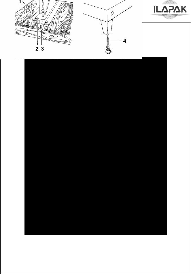
•Remove the screws (1) attaching the support channels (2) to the pallet.
•Operating from the back of the machine, position the forklift under the base plate, and lift the machine at a height sufficient to permit pallet removal.
•Remove the four bolts (3) that attach the support channels to the machine, and replace them with the four adjustable feet (4).
•Lower the machine to the ground, remove the forklift, and carry out machine levelling as described in the following paragraph
© Copyright ILAPAK Italia S.p.a |
Ed 1 Rev 06 - June 2005 |
PAGE -15 |
Carrera 2000 PC Touch
ATTENTION: ☺ SCRAP PACKING IN THE FIT DUMP
DON'T LEAVE PACKING IN THE ENVIRONMENT !!
OPERATE FROM BACK SIDE
1.Attachment Screw,
2.Support channel to Pallet
3.Support Channel Attachment Bolt, Support Channel to Machine
4.Adjustable foot
Machine unpacking and positioning
© Copyright ILAPAK Italia S.p.a |
Ed 1 Rev 06 - June 2005 |
PAGE -16 |

Carrera 2000 PC Touch
WARNING |
The instructions supplied in this chapter are a synthesis of the procedures |
|
established during the assembling of the machine and are destined to |
|
technical staff, already in possession of the necessary knowledge for this |
|
operation. However the staff should always be accompanied by specialised |
|
ILAPAK staff. The purpose of these instructions is to supply a general |
|
description of the methods, used for the connection of the main groups, |
|
composing the machine. |
LEVELLING
The machine has to run in perfect horizontal direction and should transmit only a minor quantity of possible vibrations on the floor where it is installed; for this purpose, after having placed it on the operation site, proceed with the levelling acting on the proper supporting feet on the base and acting on the four adjustable feet, using as reference the counter plane. At the end of the procedure, block the four feet by means of the related lock nuts.
WARNING |
The levelling of the machine should be carried out with exact precision in |
|
order to avoid torsion phenomenon, an incorrect parallelism of the planes |
|
and unexpected loads on the elements. The constructor declines each |
|
responsibility for damages or malfunctioning of the machine, deriving from |
|
an incorrect levelling or from a missing execution of the established |
|
periodical checks. |
© Copyright ILAPAK Italia S.p.a |
Ed 1 Rev 06 - June 2005 |
PAGE -17 |
Carrera 2000 PC Touch
ATTACHMENT OF INFEED CONVEYOR
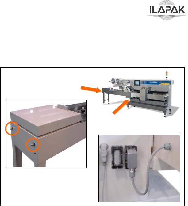
Attach the infeed conveyor by following this procedure:
Place the infeed conveyor on its support casting on the machine body making sure that it rests on the casting correctly.
If necessary, level the infeed conveyor by adjusting the two support feet.
Insert the two paper pins for infeed alignment (these pins are supplied with the machine) then install the four attachment bolts with their washers
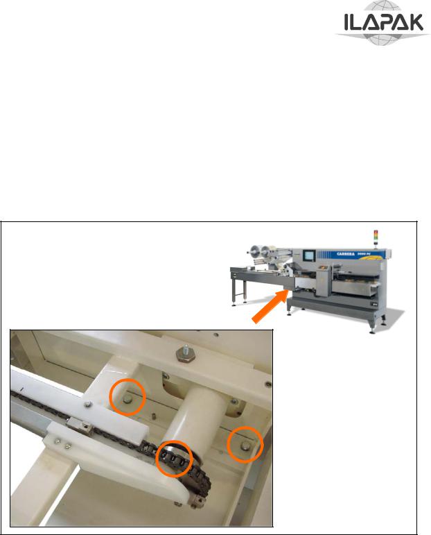
•Connect the infeed conveyor chain by following the follows procedure:
•If necessary, slacken the chain using the two side tensors.
•Join the chain ends on the sprocket by use of the special link and the relevant retaining clips.
•Adjust the chain tension by use of the special side tensors, making sure that the chain is not too tensioned, and that distance “X” measured between the end of the tensor and the sprocket shaft is the same for both tensors.
© Copyright ILAPAK Italia S.p.a |
Ed 1 Rev 06 - June 2005 |
PAGE -18 |
Carrera 2000 PC Touch
CAUTION. A too tensioned chain may result in bending of the sprocket shaft and damage to the infeed conveyor.
•Plug the electrical connector of the auxiliary control panel of the infeed conveyor into socket on the left (or right) side of the machine
© Copyright ILAPAK Italia S.p.a |
Ed 1 Rev 06 - June 2005 |
PAGE -19 |

Carrera 2000 PC Touch
ELECTRICAL SYSTEM CONNECTION
CAUTION: Connection of the machine to the electrical mains power is carried out by the user under his/her full and sole responsibility,
and in compliance with the following instructions:
1.Make sure that the mains power characteristics correspond to those of the machine.
2.Open the electrical cabinet and connect the power supply wires to the terminal board by referring to the applicable interconnection diagrams shown in Section wiring diagrams of this manual.
3.Connect the end of the power supply cable to a mains circuit breaker (thermal or magnetic) according to the machine connection sequence.
EARTHING
The machine should be earthed by means of a centralised line, available on the installation site. The main earthing joint with the outer line is realized inside the electrical board.
© Copyright ILAPAK Italia S.p.a |
Ed 1 Rev 06 - June 2005 |
PAGE -20 |

Carrera 2000 PC Touch
PNEUMATIC SYSTEM (OPTIONAL)
The machine pneumatic system is designed to the closing of sealing – propelling rollers
In addition to other optional devices such as: Air gusseting
Air Ejector Automatic reel splicer
Quality Control
The system is fed directly from the air supply line available at the machine installation location, through the filter-pressure regulator that is normally set at a pressure of 6-7 bars.
The system is fully controlled by selector valves whose closing and opening is electronically commanded according to the operating parameters set by the operator. Each selector valve is also fitted with a pressure regulator that regulates the compressed air discharge pressure.
COOLANT INSTALLATION CONNECTION (OPTIONAL)
The machine can be equipped with a coolant installation, provided with a specific water input and output; Check that the water inlet and outlet pipe on the machine are correctly connected from the distribution block to the users.
CLEANING
Carry out an accurate cleaning of the machine at the end of the installation; remove the dust and the present residues with particular care to the sliding surfaces. Furthermore check that there aren’t any oil remnants near the tank of the lubrication installation.
Use a compressed air blowing device and a dry cloth for the cleaning in order to remove the dust and also a non-aggressive solvent.
© Copyright ILAPAK Italia S.p.a |
Ed 1 Rev 06 - June 2005 |
PAGE -21 |

Carrera 2000 PC Touch
MACHINE DEMOLITION
The machine demolition should be performed by staff specialised in the electric and mechanic field. The standards in force concerning these operations are often different in the various Countries, so it is recommended to analyse and apply all the provisions stated by laws at the moment the machine is to be dismissed. The machine has been realised using non-dangerous materials, (steel, plastics, rubber), which won’t give any problems for recycling or disposal at the end of the service; anyway, it is necessary to have a deep knowledge of the machine construction features and great technical skills to disassemble the machine, besides the specific tools. It is strongly recommended to contact ILAPAK assistance service, in order to obtain the maximum safety conditions in carrying out this job.
WARNING It is necessary to provide for the oil recovery and its differentiated disposal according to the antipollution standards.
© Copyright ILAPAK Italia S.p.a |
Ed 1 Rev 06 - June 2005 |
PAGE -22 |

Carrera 2000 PC Touch
MACHINE CONTROLS
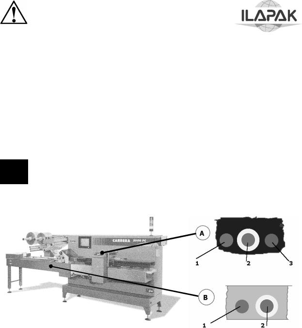
PUSH BUTTONS AND OTHER ELECTRO-MECHANICAL DEVICES
Push buttons and switches are located on the console except for the mains isolator switch on the door of the electrical cabinet on the rear of the machine.
Green push button POWER UP / START (3)
With the mains isolator on, powers the machine up or resets power after one of the following events:
use of the EMERGENCY STOP push button
opening of an interlocked guarding during operation of the machine mains cut-off
Sets the machine in motion after powering up; in specific conditions executes also the following functions:
reset an alarm or error message on the display screen
initialises co-ordination (synchronisation) of the “axes” (separate drive motors of carriage, jaws, product infeed, sealing-propelling rollers and film unwinding roller), when in a non-synchronised condition.
NOTE: Synchronising of the axes will take place automatically upon pushing the START button, each time the axes are not any more in their "normal" positions, in particular after:
turning on the mains; a mains cut-off;
a size change;
operating one single axis separately; a film rupture;
operation of the “electronic safety clutch”, i.e. when a product has got caught in the sealing jaws.
co-ordinated start of all motors (under normal operating conditions); the machine will accelerate continuously up to the speed set on the speed control potentiometer.
Red push button POSITIONAL STOP (1)
makes the machine come to a halt in a pre-defined position with open sealing jaws (so that the film will not be burnt). Normally, after pushing this button the machine will reduce speed and approach the correct position at lower speed.
© Copyright ILAPAK Italia S.p.a |
Ed 1 Rev 06 - June 2005 |
PAGE -23 |
Carrera 2000 PC Touch
Emergency stop button EMERGENCY STOP (2)
Stops the machine with IMMEDIATE effect independent of its momentary position;
In agreement with ECand other international regulations the operation of the emergency stop push button has the following effects:
•Power off the complete machine;
•cut all outputs from the electronic control system;
•release compressed air from all pneumatic systems under pressure.
•In order to return to working conditions after operating the EMERGENCY STOP button, it is necessary to unlock it by rotating it in the direction of the arrow.
NOTE: The emergency stop button must not be used other than in case of real danger or any other emergency situation necessitating an immediate machine stop.
Using the emergency stop button for “normal” machine stoppages violates the safety regulations and may lead to damage on the machine and/or the products to be wrapped.
© Copyright ILAPAK Italia S.p.a |
Ed 1 Rev 06 - June 2005 |
PAGE -24 |
Loading...