

Page 1

Carrera 2000 PC Touch
SALES AGENTS AND SERVICE ORGANISATIONS.........................................................1
SPARE PARTS ..........................................................................................................1
INTRODUCTION .........................................................................................................2
WARNINGS FOR USE OF THE INSTRUCTIONS............................................................2
PURPOSE AND LIMITS OF THE INSTRUCTION AND MAINTENANCE MANUAL .............2
KEEPING OF THE MANUAL.....................................................................................2
UPDATING OF THE MANUAL ..................................................................................2
COLLABORATION WITH THE USER.........................................................................2
MACHINE IDENTIFICATION DATA .............................................................................3
EC STAMPING AND SAFETY STANDARDS...................................................................... 4
SAFETY RULES.........................................................................................................5
CLOTHING...............................................................................................................7
ACCESS TO THE WORKING ZONE ..............................................................................7
MACHINE USE DESTINATION....................................................................................8
MACHINE APPLICATION ...........................................................................................8
VALUATION OF RISKS..............................................................................................9
RISKS LINKED TO THE INSTALLATION SITE OF THE MACHINE.................................9
RISKS LINKED TO THE FEATURES OF THE MACHINE...............................................9
RESIDUE RISKS ZONES AND OPERATIONS...............................................................10
WARNING SIGNS ...................................................................................................10
RESIDUE DANGERS................................................................................................11
WORKING AND CONTROL ZONES - SAFETY ZONES ..................................................
ENVIRONMENTAL USE CONDITIONS .......................................................................
11
12
NOISE LEVEL ......................................................................................................12
TEMPERATURE AND HUMIDITY............................................................................
OPERATIONAL SITE.............................................................................................
12
12
ILLUMINATION ...................................................................................................12
VIBRATIONS.......................................................................................................12
RESIDUE AND ENVIRONMENTAL CONTAMINATION ...............................................12
SAFETY DEVICES ...................................................................................................13
MACHINE INSTALLATION..........................................................................................14
INSTALLATION SITE REQUIREMENTS......................................................................14
EXTERNAL INSTALLATION REQUIREMENTS .............................................................14
UNPACKING...........................................................................................................
MACHINE UNPACKING AND POSITIONING...............................................................
14
14
LEVELLING ............................................................................................................17
ATTACHMENT OF INFEED CONVEYOR .....................................................................18
Copyright ILAPAK Italia S.p.A. Ed 1 Rev 06 - June 2005 User manual –- 1
Page 2

Carrera 2000 PC Touch
ELECTRICAL SYSTEM CONNECTION ........................................................................20
EARTHING.............................................................................................................20
PNEUMATIC SYSTEM (OPTIONAL)...........................................................................21
COOLANT INSTALLATION CONNECTION (OPTIONAL)...............................................21
CLEANING .............................................................................................................21
MACHINE DEMOLITION.............................................................................................22
MACHINE CONTROLS................................................................................................23
PUSH BUTTONS AND OTHER ELECTRO-MECHANICAL DEVICES.................................23
SIGNAL LAMPS.......................................................................................................25
USER INTERFACE......................................................................................................26
DISPLAY................................................................................................................26
OPERATIVE KEYS...................................................................................................28
MULTIFUNCTIONAL KEYBOARD...............................................................................29
RECALL KEYS.........................................................................................................30
HELP ON LINE .........................................................................................30
PRELIMINARY OPERATION........................................................................................31
LANGUAGE SELECTION...........................................................................................31
USER PASSWORD...................................................................................................33
ENTERING THE PASSWORD....................................................................................34
DEACTIVATION OF THE PASSWORD........................................................................
MODIFICATION OF PASSWORD “OPERATOR”...........................................................
36
37
OPERATION CYCLE START.........................................................................................39
BASE PAGE............................................................................................................
CREATION OF A NEW PRODUCT .............................................................................
40
41
CREATION OF A NEW DATABASE .........................................................................42
MECHANICAL MACHINE ADJUSTMENTS......................................................................45
DETERMINING THE STEP OF THE PRODUCT FEED LUGS...........................................45
INSERTING THE INFEED LUGS................................................................................46
FIXED FOLDING BOX...........................................................................................47
ADJUSTABLE FOLDING BOX (OPTIONAL)..............................................................48
ADJUSTABLE FOLDING BOX (OPTIONAL)..............................................................48
ADJUSTING PRODUCT GUIDES.............................................................................
DETERMINING THE WIDTH OF THE REEL................................................................
49
50
MOUNTING FILM REELS .........................................................................................50
INSERTING FILM....................................................................................................
Copyright ILAPAK Italia S.p.A. Ed 1 Rev 06 - June 2005 User manual –- 2
51
Page 3
Carrera 2000 PC Touch
ADJUSTING THE MECHANICAL ARM ........................................................................52
ADJUSTING THE FILM REEL BRAKE.........................................................................53
JAW HEIGHT ADJUSTMENT.....................................................................................54
VERSION “CARRERA 2000 PC 400” .......................................................................54
JAW HEIGHT SELECTION.....................................................................................54
VERSION “CARRERA 2000 PC 250” .......................................................................55
MOUNTING THE INTERCHANGEABLE PRODUCT SUPPORT ........................................56
ENTERING PRODUCT DIMENSIONS AND ADJUSTMENTS..............................................57
ENTERING THE OPERATING PARAMETERS OF THE MACHINE ....................................61
“TEMPERATURE” PAGES .........................................................................................62
“TEMPERATURES ACCORDING TO THE MACHINE SPEED ............................64
PAGE “PRODUCTION RELATED DATA”.....................................................................66
OFF SET PARAMETER ...........................................................................68
“ACCESSORIES” PAGE ............................................................................................69
DESCRIPTION OF PARAMETERS ....................70
ACCESSOIRES PAGE: PRINTER/GUSSET/CARDBOARD CUTTER...............................71
PRINTER ...........................................................................................71
GUSSET ............................................................................................71
CARDBOARD CUTTER
INDEPENDENT CUT
.....................................................................72
.........................................................................72
ACCESSOIRES PAGE: LABEL APPLICATOR/SPRAY...................................................73
LABEL APPLICATOR ............................................................................73
SPRAY ...............................................................................................73
VARIOUS ACCESSORY PAGES...............................................................................74
"USER CAMS" PAGE ....................................................................................75
Copyright ILAPAK Italia S.p.A. Ed 1 Rev 06 - June 2005 User manual –- 3
Page 4
Carrera 2000 PC Touch
PAGE “FUNCTIONS” ....................................................................................78
PRE-PRODUCTION....................................................................................................81
VERIFICATION OF SETTINGS AND ADJUSTMENTS....................................................81
ADDITIONAL TESTING PROCEDURES WITH REGISTERED PRINT ......................... 82
TEST RUN..............................................................................................................85
ADVANCED FUNCTIONS: MISPLACE - NO PRODUCT NO BAG .....................................87
PRODUCT SAFETY SYSTEM (MISPLACE) .....................................................87
INTRODUCTION OF THE FUNCTION “PRODUCT SAFETY”......................................88
ENTERING PARAMETERS .....................................................................................89
ACTIVATION OF THE FUNCTION “PRODUCT SAFETY” (MISPLACE)..........................91
“NO PRODUCT / NO BAG” .................................................................92
NOTES FOR THE CORRECT CALIBRATION OF THE PHOTOCELL..............................92
CONDITIONS FOR THE CORRECT FUNCTIONING................................................92
OPERATING RULES...........................................................................................92
ACTIVATING THE “NO PRODUCT / NO BAG” FUNCTION......................................93
AVAILABLE INSTRUMENTS................................................................................93
OPERATING .....................................................................................................94
DATA NEEDED FOR THE AUTOMATIC CALCULATION...........................................94
HOW TO CHANGE THE PRODUCT STOP POSITION..............................................96
USE OF THE FILM ADVANCE..............................................................................
FORCING OF THE FILM STOP CYCLE AT THE CUT-OFF........................................
SAVING PARAMETER VALUES
......................................................................98
96
97
PRODUCTION.........................................................................................................100
SIZE CHANGE
...........................................................................................102
STATISTICS ..............................................................................................104
PRODUCTS LIST MANAGEMENT...............................................................................105
DELETION OF A PRODUCT ........................................................................105
COPYING A PRODUCT ...............................................................................107
Copyright ILAPAK Italia S.p.A. Ed 1 Rev 06 - June 2005 User manual –- 4
Page 5

Carrera 2000 PC Touch
CORRECTING/CHANGING A PRODUCT NAME .........................................................109
DIAGNOSTIC..........................................................................................................111
“DIAGNOSTIC” PAGE............................................................................................111
“INFEED AXIS” PAGE............................................................................................112
“FILM AXIS” PAGE................................................................................................113
“ROLLER AXIS” PAGE............................................................................................114
“JAW AXIS” PAGE.................................................................................................115
“DISCHARGE BELT” PAGE (OPTIONAL)..................................................................116
“AUTOMATIC FEEDER” (OPTIONAL) ......................................................................117
“TEMPERATURE” PAGE.........................................................................................118
“I/O STANDARD” PAGE.........................................................................................119
“DIGITAL INPUT” PAGE ........................................................................................120
“DIGITAL OUTPUT” PAGE .....................................................................................121
“ANALOG INPUT/OUTPUT” PAGE...........................................................................122
“ALARM LIST” PAGE .............................................................................................123
TROUBLESHOOTING...............................................................................................124
MACHINE MALFUNCTION DURING OPERATION......................................................124
ERROR MESSAGES ...............................................................................................139
MESSAGGE ..........................................................................................................139
PROBLABLE CAUSE / REMEDY............................................................................139
MAINTENANCE .......................................................................................................142
GENERAL.............................................................................................................142
SAFETY CONDITION.............................................................................................
PUTTING IN MAINTENANCE CONDITION...............................................................
142
143
PERIODICAL MAINTENANCE .................................................................................143
MACHINE.............................................................................................................
MACHINE MAINTENANCE......................................................................................
144
146
FRAME CLEANING AND MAIN COMPONENTS.......................................................146
INFEED CONVEYOR...........................................................................................146
MACHINE BODY ................................................................................................146
LONGITUDINAL SEALING AND PROPELLING ROLLERS .........................................147
JAWS................................................................................................................147
DISCHARGE CONVEYOR BELT ............................................................................147
JAW AND ROLLER HEATER ROTARY COLLECTORS...............................................147
LEVELLING CHECK.............................................................................................
MECHANICAL PARTS MAINTENANCE......................................................................
147
148
BOLTS AND NUTS TIGHTENING CHECK ..............................................................148
WEAR AND TEAR CHECK AND REEL BRAKE OPERATION: .....................................148
Copyright ILAPAK Italia S.p.A. Ed 1 Rev 06 - June 2005 User manual –- 5
Page 6

Carrera 2000 PC Touch
LUBRICATION OF DRIVE CHAINS .......................................................................148
CHECK OF TRANSMISSION BELT TENSION..........................................................148
CHECK OF MOTOR BELT....................................................................................148
MAINTENANCE MOTOR – ADAPTORS – VARIATOR .................................................149
CHECK AND OIL REPLACEMENT..........................................................................149
MAINTENANCE OF SAFETY DEVICES .....................................................................150
EFFICIENCY CHECK OF THE EMERGENCY STOP BUTTON .....................................150
EFFICIENCY CHECK OF THE SAFETY SWITCHES..................................................150
ELECTRICAL INSTALLATION MAINTENANCE...........................................................151
CABLES FIXING CHECK......................................................................................151
MAINTENANCE PUSHBUTTONS, CONTROL SELECTORS AND INDICATORS.............151
PNEUMATIC INSTALLATION MAINTENANCE (OPTIONAL)........................................152
CONDENSATION DRAINAGE AND PRESSURE REGULATOR FILTER CLEANING ........152
LUBRICATING OIL LEVEL CHECK........................................................................152
EFFICIENCY CHECK OF THE PNEUMATIC INSTALLATION COMPONENTS................154
COOLANT INSTALLATION MAINTENANCE (OPTIONAL) ...........................................155
WATER CIRCULATION CHECK ............................................................................155
COOLANT CIRCUITS PIPING CHECK....................................................................155
AIR CLEANING FILTER REPLACEMENT...................................................................156
REPLACEMENT OF COMPONENTS..........................................................................157
REPLACEMENT OF UPPER JAW KNIFE.................................................................157
ADJUSTMENT OF UPPER JAW KNIFE...................................................................157
REPLACEMENT OF LOWER JAW ANVIL................................................................157
REPLACEMENT OF HEATING RESISTANCES CARBON BRUSHES.............................159
JAW HEATER..................................................................................................159
SEALING ROLLER HEATERS.............................................................................
REPLACEMENT OF HEATER RESISTANCES...........................................................
159
161
UPPER JAW HEATER.......................................................................................161
LOWER JAW HEATER......................................................................................
SEALING ROLLER HEATERS................................................................................
161
162
REPLACEMENT OF TEMPERATURE PROBES .........................................................162
UPPER AND LOWER JAW TEMPERATURE PROBE...............................................162
SEALING ROLLER TEMPERATURE PROBE ............................................................163
Copyright ILAPAK Italia S.p.A. Ed 1 Rev 06 - June 2005 User manual –- 6
Page 7

Carrera 2000 PC Touch
SALES AGENTS AND SERVICE ORGANISATIONS
The Sales Agent and Service Organisation in your area is:
TO BE FILLED IN BY THE AGENT OR AREA REPRESENTATI VE
The machine subject of this publication was designed by ILAPAK S.p.A. (Nova Milanese;
Milano; Italy), which is a company of the ILAPAK group.
ILAPAK ITALIA S.p.A. puts its proper Assistance Service at disposition of the customers in
order to solve whatever problem regarding the use and the maintenance of their
machines.
The customers can signal their requests to the related commercial ILAPAK
companies.
SPARE PARTS
It is recommended to use exclusively original spare parts.
The requests for spare parts should be made at the related commercial ILAPAK
Company, observing the standards contained in the catalogue of the spare parts and
nominating always the type and serial number of the machine.
Copyright ILAPAK Italia S.p.a
Ed 1 Rev 06 - June 2005 PAGE -1
Page 8

Carrera 2000 PC Touch
INTRODUCTION
WARNINGS FOR USE OF THE INSTRUCTIONS
PURPOSE AND LIMITS OF THE INSTRUCTION AND MAINTENANCE
MANUAL
This manual is destined to all the operators in charge of the use, maintenance and
surveillance of the machine during its working life.
The purpose of the manual is to supply the information regarding:
- The technical features of the machine
- The preparation of the working site regarding the environmental characteristics and
the feeding sources
- The accident prevention standards, use and calibration of the safety devices
- The use of the machine as provided in the project
- The ordinary and extraordinary maintenance
- The availability of the spare parts
The manual cannot replace the specific preparation, which the operators should have
carried out previously on equal appliances or who will be accompanied on this machine by
already skilled staff.
KEEPING OF THE MANUAL
The use and maintenance manual is considered integral part of the machine and should
be kept for future reference till the final dismantling of the machine.
The manual should always be available for consultation and should be kept with care; in
case of damaging which compromises also partially the consultation, the user has to ask a
new exemplar to the constructor.
UPDATING OF THE MANUAL
This manual has been prepared at the same time with the realization of the referred
machine and cannot be considered inadequate only because successively updated (also
for similar machines) according to new experiences.
ILAPAK ITALIA S.p.A. has the right to modify together with its production also the related
manuals, without the obligation to update the previous supplied ones. Possible
integrations sent to the users, under the form of “UPDATING”, have to be kept together
with the manual.
COLLABORATION WITH THE USER
ILAPAK ITALIA S.p.A. is at disposition of its customer to supply further information
regarding the use and the maintenance of their machines as well as considering
improving proposals for the manual in order to make them always more suitable to the
requirements of the customers.
Copyright ILAPAK Italia S.p.a
Ed 1 Rev 06 - June 2005 PAGE -2
Page 9
Carrera 2000 PC Touch
MACHINE IDENTIFICATION DATA
The main identification data of the machine are printed on the proper plate with the EC
marking installed outside the machine.
The plate notes the following data:
- Name of manufacturer and his address
- Type of machine
- Serial number
- Construction date
- Feeding voltage
- Absorbed power
- EC marking
Another plate, fixed inside the electrical panel, notes furthermore the values in relation to
the electrical supply
- Serial number of the electrical panel
- Nominal voltage
- Frequency
- Number of phases
- Frequency
- Full load current
- Number of the wiring diagram
- Short-circuit interruption power
NOTE In case of a technical assistance request or an order of the spare parts, nominate
always the type and serial number of the machine a/o the data in relation to the
electrical supply.
Machine identification
Copyright ILAPAK Italia S.p.a
Ed 1 Rev 06 - June 2005 PAGE -3
Page 10

Carrera 2000 PC Touch
EC STAMPING AND SAFETY STANDARDS
The machine bears the EC stamp indicating conformity with Directive 89/392/EEC,
and subsequent modifications, of the European Community Council.
NOTE: The stamp is affixed to the machine nameplate.
The original copy of “EEC Statement of conformance” is handed over to the customer
at the time of machine delivery.
This document shall be carefully kept by the Customer, and produced upon request
by the concerned Authorities.
The “EEC Statement of Conformance” is to be considered an integral part of the
machine, and shall be transferred to the new owner whenever the machine is re-sold.
Copyright ILAPAK Italia S.p.a
Ed 1 Rev 06 - June 2005 PAGE -4
Page 11

Carrera 2000 PC Touch
SAFETY RULES
The following safety rules should be observed during installation, operation
and maintenance of the machine. Lack of compliance with the following rules
may result in impaired effectiveness of the machine safety features.
The staff in charge of the use, the maintenance and the surveillance of the machine
should be instructed by the employer regarding the accident risks, the safety devices
installed on the machine and the general accident prevention rules, provided by the
international norms and the laws of the country where the machine is installed.
ILAPAK denies any liability for machine damage or injuries to the operator
third parties arising from the lack of compliance with the safety rules listed
hereafter.
MACHINE DISPLACEMENT DURING INSTALLATION MUST BE CARRIED OUT
ONLY BY SPECIALISED PERSONNEL, AND BY USE OF SUITABLE LIFTING
AND TRANSPORTATION EQUIPMENT.
MAKE SURE THAT ALL NECESSARY PRECAUTIONS ARE TAKEN DURING
LIFTING OR TRANSPORTATION OF THE MACHINE, AND THAT ALL THE
INSTRUCTIONS CONTAINED IN THIS MANUAL ARE CAREFULLY ADHERED
TO.
MACHINE CONNECTION TO THE ELECTRICAL POWER MEANS
SHALL BE CARRIED OUT ONLY BY SKILLED PERSONNEL.
BEFORE CONNECTING MACHINE TO THE ELECTRICAL POWER
MAINS, MAKE SURE THAT THE MAINS ELECTRICAL CHARACTERISTICS
CORRESPOND TO THOSE SPECIFIED ON THE MACHINE NAMEPLATE. ALSO,
MAKE SURE THAT THE MAINS IS PROVIDE WITH A SUITABLE GROUND
WIRE, AND THAT THE VOLTAGE MEASURED ON THE NEUTRAL WIRE IS
ZERO.
THE WIRES OF THE ELECTRICAL CONNECTION CABLE SHALL HAVE
A MINIMUM CROSS-SECTION OF 4 SQUARE MM.
THE MACHINE SHALL BE OPERATED ONLY BY SKILLED AND AUTHORISED
PERSONNEL.
THE MACHINE OPERATOR SHALL MAKE SURE THAT ALL THE
INSTRUCTIONS GIVEN IN THIS MANUAL ARE CORRECTLY FOLLOWED.
JAW MOTION REPRESENTS THE GREATEST DANGER FOR THE
OPERATOR WHEN THE MACHINE IS RUNNING. IN ORDER TO PROTECT THE
OPERATOR, THE MACHINE IS PROVIDED WITH A SAFETY DEVICE THAT
PERMITS MACHINE OPERATION ONLY WHEN THE PROTECTION GUARDING
ARE CLOSED.
Copyright ILAPAK Italia S.p.a
Ed 1 Rev 06 - June 2005 PAGE -5
Page 12

Carrera 2000 PC Touch
IN CASE OF MAINTENANCE OR REPAI R ACTIONS REQUIRING THAT
THE MACHINE OPERATES WITH PROTECTION GUARDING OPEN (SAFETY
DEVICE CUT OUT), PROCEED WITH EXTREME CAUTION TO PREVENT
HAZARDS OR INJURIES TO THE OPERATOR.
IN CASE OF DANGER FOR THE OPERATOR, OR WHENEVER IT IS
NECESSARY TO IMMEDIATELY STOP THE MACHINE, PRESS THE RED
EMERGENCY STOP PUSH-BUTTON. THIS BUTTON STOPS THE MACHINE AT
ONCE IRRESPECTIVE OF THE KIND OF WORKING OPERATIONS IN
PROGRESS.
THE USER IS RESPONSIBLE FOR THE OPERATIONAL SAFETY OF ANY
AUXILIARY EQUIPMENT NOT SUPPLIED BY ILAPAK.
ANY ACTION ON THE MACHINE WHICH MAY INTERFERE WITH THE SAFETY
DEVICES IS CARRIED OUT AT THE OPERATOR’S RISK.
IN CASE OF MAINTENANCE OR REPAIR ACTIONS REQUIRING
OPENING OR DISABLING OF PROTECTIONS, PROCEED WITH THE UTMOST
CARE AND IMPLEMENT ALL THE APPLICABLE SAFETY MEASURES. THESE
ACTIONS SHALL BE CARRIED OUT ONLY BY AUTHORISED PERSONNEL.
MAKE SURE THAT THE ELECTRICAL POWER SUPPLY IS
DISCONNECTED AND THE PNEUMATIC SYSTEM IS DISCHARGED BEFORE
CARRYING OUT ANY ADJUSTMENT/CALIBRATION OF THE MACHINE.
MAKE SURE THAT THE MACHINE IS DISCONNECTED FROM THE
ELECTRICAL POWER MAINS BEFORE CARRYING OUT ANY CLEANING OR
LUBRICATION OPERATION. POSITIVELY AVOID DIRECTING WATER JETS
ON THE MACHINE, INSIDE IT, ON THE CONTROL PANEL, AND ABOVE ALL
INSIDE THE ELECTRICAL CABINET.
DO NOT EMBODY MODIFICATIONS IN THE MACHINE WITHOUT PRIOR
AUTHORISATION BY ILAPAK.
ANY MODIFICATION SHALL BE EMBODIED BY ILAPAK AUTHORISED
PERSONNEL ONLY, AND RECORDED IN THE APPLICABLE TECHNICAL
DOCUMENTATION. ANY TAMPERING OF THE MACHINE, OR MODIFICATION
PERFORMED BY THIRD PARTIES VOIDS ANY RESPONSIBILITY OF ILAPAK
IN CASE OF MALFUNCTION OR INJURY TO THE OPERATOR.
Copyright ILAPAK Italia S.p.a
Ed 1 Rev 06 - June 2005 PAGE -6
Page 13

Carrera 2000 PC Touch
CLOTHING
The clothing of the operator or the person, who carries out maintenance on the machine
should be according to the legal safety rules in the country of application. In general, the
operator should wear accident prevention shoes, and it is forbidden to wear moccasins,
clogs, slippers or any kind of footwear that could compromise the mobility of the person.
Use proper thermo-protective fireproof gloves when working in areas, which are
characterised by heat emission.
NOTE : When working on the machine, don’t wear bracelets, watches, rings or chains
which can dangle or hinder movements. Pay maximum attention, when working
near moving parts of the machine, that the proper clothing is suitable and avoid
hitching up with these devices (sleeves, shirt tails, hair, etc.)
ACCESS TO THE WORKING ZONE
The working area should never be occupied so that nothing interferes with the freely
movement of the operator. The immediate access to the machine from the staff in charge
should be guaranteed in emergency cases.
It is forbidden to have access to the working area to people who are not directly in
charge with the operation of the machine. This should be signalled with proper signs.
ATTENTON During the maintenance operations , in particular way when you work with
protections or disconnected safety devices, it is necessary to pay the
maximum attention that the working area is not accessible to people, who
are not directly in charge with these operations. At the end of the
maintenance interventions verify that no used tool remains inside the
accident prevention guards or inside the working area.
Copyright ILAPAK Italia S.p.a
Ed 1 Rev 06 - June 2005 PAGE -7
Page 14

Carrera 2000 PC Touch
MACHINE USE DESTINATION
MACHINE APPLICATION
THE WRAPPING MACHINE MODEL CARRERA 2000 PC IS DESIGNED TO WRAP
FOOD PRODUCTS AND INERT MATERIALS.
IT MAY NOT BE USED TO WRAP PRODUCTS WHICH MIGHT REPRESENT A
SAFETY HAZARD FOR THE OPERATOR OR SEVERELY DAMAGE THE MACHINE
POSITIVELY DO NOT WRAP GAS-CONTAINING BOTTLES,
CONTAINERS OR JELLIES OF THE FOLLOWING MATERIALS: GUN POWDER
OR SIMILAR MATERIALS, FLAMMABLE FLUIDS, GLUES, SOLVENTS, ETHER,
ALCOHOL, GASOLINE, CATALYST AND CORROSIVE ACIDS, ETC.
POSITIVELY DO NOT WRAP ANY CHEMICALS OR OTHER
MATERIALS WHICH MAY REACT AT THE SEALING TEMPERATURES AND
RELEASE POISONOUS, FLAMMABLE OR EXPLOSIVES GASES, ETC.
WHEN THE OPERATION OF THE MOTORISED PRODUCT SUPPORT
DEVICE HAS BEEN ACTIVATED (FUNCTIONAL KEY ) AVOID THAT THE
MAXIMUM PRODUCTION SPEED EXCEEDS 90 PIECES PER MINUTE.
THE MACHINE SHOULD BE USED FOR THE WRAPPING WITH EXACTLY
DEFINED CHARACTERISTICS AND WITHIN THE LIMITS ESTABLISHED BY THE
SUPPLYING CONTRACT, DRAWN BETWEEN THE PURCHASER AND THE
CONSTRUCTOR. THE USE OF THE MACHINE TO OBTAIN HIGHER PRODUCTION
VALUES OR DIFFERENT FROM THE ESTABLISHED ONE IS CONSIDERED AS AN
IMPROPER USE AND THE CONSTRUCTOR DENIES EVERY LIABILITY FOR
DAMAGES CAUSED TO THINGS OR PEOPLE AND DOESN’T ACCEPT ANY KIND
OF GUARANTEE ON THE MACHINE.
ILAPAK DENIES ANY LIABILITY DERIVING FROM IMPROPER USE OF THE
MACHINE.
Copyright ILAPAK Italia S.p.a
Ed 1 Rev 06 - June 2005 PAGE -8
Page 15

Carrera 2000 PC Touch
VALUATION OF RISKS
Risks linked to the installation site of the machine
On the installation site of the machine there can be some risky situations, which could
compromise the correct operation.
FLOOR
The surfaces where the machine is placed on should guarantee during time the correct
placing and levelling; for example some asphalt floor under high temperatures condition
and in presence of soluble liquids can present an accelerated wear and tear with possible
formation of holes corresponding to the supporting points and therefore making the
machine position unstable.
TEMPERATURE
The established environmental temperature should be guaranteed (from 2 to 35 °C); high
temperature peaks could cause machine operation problems (for example cooling
difficulty of the motors).
POLLUTING MATERIAL
The potential damage coming from the use in the working area with polluted material
should be preventively valuated; for example:
DUST which could accelerate the wear and tear of the seals;
PVC which thermal degradation, generating HCl, can cause aggressive emissions of
the metal surfaces without proper protections.
MAGNETIC FIELDS,
Determined by the passage of electrical power lines near the electronic appliances
installed on the machine. They can cause disturbances and malfunctioning.
WARNING The user should assure the suitability of the installation place of the machine,
in order to save its integrity during time.
RISKS LINKED TO THE FEATURES OF THE MACHINE
According to the EEC 89/392 standards, all the areas of the machine characterised by
intrinsic with the working process or with the structure of the machine have been
analysed. The most suitable measurements have been taken to reduce, as well as to
eliminate possible risks to people in charge, equipping the machine with a series of
standard protections, fixed and movable, which stop the access to the dangerous areas
during the working. However, the best safeguarding for the operator’s safety is that the
operator himself pays attention and has a good sense and that the greatest experience
during time using the machine, can improve the safety margins during the operation.
Copyright ILAPAK Italia S.p.a
Ed 1 Rev 06 - June 2005 PAGE -9
Page 16
Carrera 2000 PC Touch
RESIDUE RISKS ZONES AND OPERATIONS
The areas of the machine or the procedures, which, even with suitable safety
measurements present a high danger degree are defined residue risks, for example the
presence of high voltage, high temperature or moving parts. All the areas with residue
risks have been marked with proper name plates according to the ISO standards;
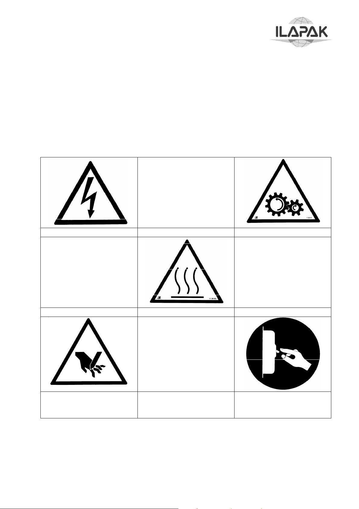
WARNING SIGNS
In compliance with the EC regulations, and in order to highlight the machine areas
requiring special operator’s attention, or involving particular hazards for operator safety,
the following warning signs are used.
LIVE LINE
HOT SPOT
CUT/SEVER HAND AND
FINGERS
MOVING GEARS
PUT TENSION OFF
BEFORE WORKING
INSIDE
Copyright ILAPAK Italia S.p.a
Ed 1 Rev 06 - June 2005 PAGE -10
Page 17
Carrera 2000 PC Touch
RESIDUE DANGERS
INFEED CONVEYOR END
There is the danger that your hands may caught and crushed where
product lugs return upward at the end of the infeed conveyor. Therefore,
avoid working in this area, and pay much attention if working there cannot
be avoided.
ADJUSTMENT OF PRODUCT GUIDES
Adjustment of the product guides shall be such as there is a gap of less
than 5 millimeters or of more than 25 millimeters between the guide and
the pusher.
If the product to be wrapped requires that the distance between the guide
and the pusher is set a value between 5 and 25 mm, pay much attention as
you run the risk that your hands are caught between the guide and the
pusher.
CONVEYOR AREA
Lug overturning creates a serious danger for your hands. They may be
crushed. Pay much attention when working in this area.
LOADING OF FILM REELS
The loading of reels weighing between 18 and 36 kg shall be made by two
people.
Load the heavier reels by use of a suitable equipment (not supplied with
the machine).
WORKING AND CONTROL ZONES - SAFETY ZONES
The description of the working and control areas, is indicated in the layout included with
the statement of conformance.
Copyright ILAPAK Italia S.p.a
Ed 1 Rev 06 - June 2005 PAGE -11
Page 18

Carrera 2000 PC Touch
ENVIRONMENTAL USE CONDITIONS
NOISE LEVEL
The noise emitted by the wrapping machine during operation is 73 dB as resulting from
the measurements carried out by using a sample machine.
TEMPERATURE AND HUMIDITY
The machine can be used in rooms with room temperature included between 2 and 35 °C
and with a related humidity lower than 80 %.
OPERATIONAL SITE
The machine should be used protected against atmospheric conditions (rain, hail, snow,
fog, etc.). Should the machine be used in corrosive sites, it is necessary to intervene on
the modality and the maintenance periods, adapting it in order to avoid an excessive
wear and tear of the components.
The use of the machine under explosive or partially explosive conditions isn’t
provided, therefore it is forbidden to use it under these conditions.
ILLUMINATION
The room where the machine is placed should be illuminated in such a way to individuate
easily the buttons and the devices for the control and the emergency stop.
The illumination should allow carrying out under safety condition the ordinary
maintenance operations; the user should carry out these interventions according to the
legal rules regarding the modality of the illumination.
VIBRATIONS
Under normal use conditions, following the indications from this manual, the vibrations
may not cause danger situations. In case of anomalous vibrations, stop immediately the
machine and get in touch with the assistance service.
RESIDUE AND ENVIRONMENTAL CONTAMINATION
If the used material for the production is elaborated according to the recommendations of
the constructor, there won’t be noxious substances, as regards the EN 626-1 standards.
In case of using toxic or noxious plastic materials, the user has to install proper fume
aspiration hoods and the training of the operators for a correct treatment of these
materials. The user should observe the legal standards and community rules also for the
treatment and the lubrications used on the machine.
Copyright ILAPAK Italia S.p.a
Ed 1 Rev 06 - June 2005 PAGE -12
Page 19
Carrera 2000 PC Touch
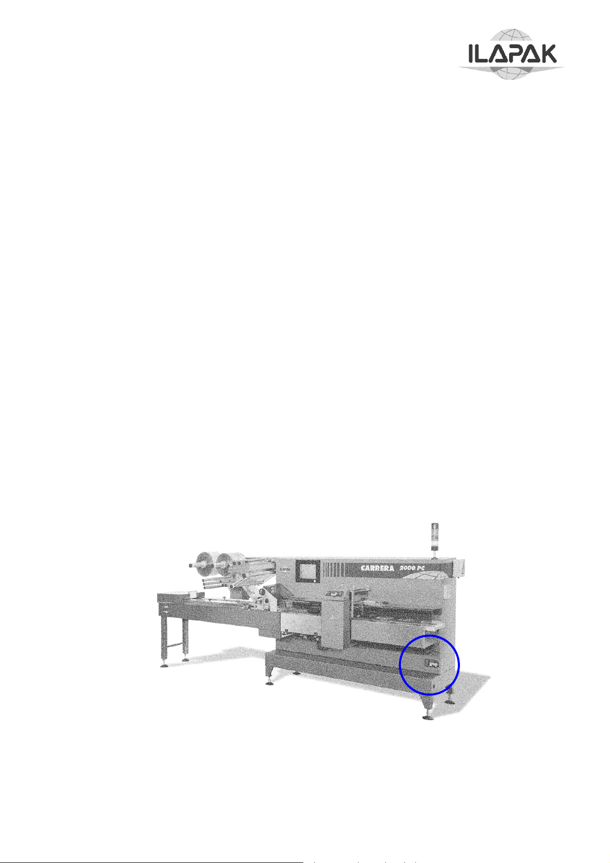
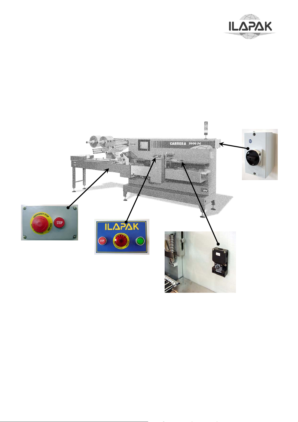
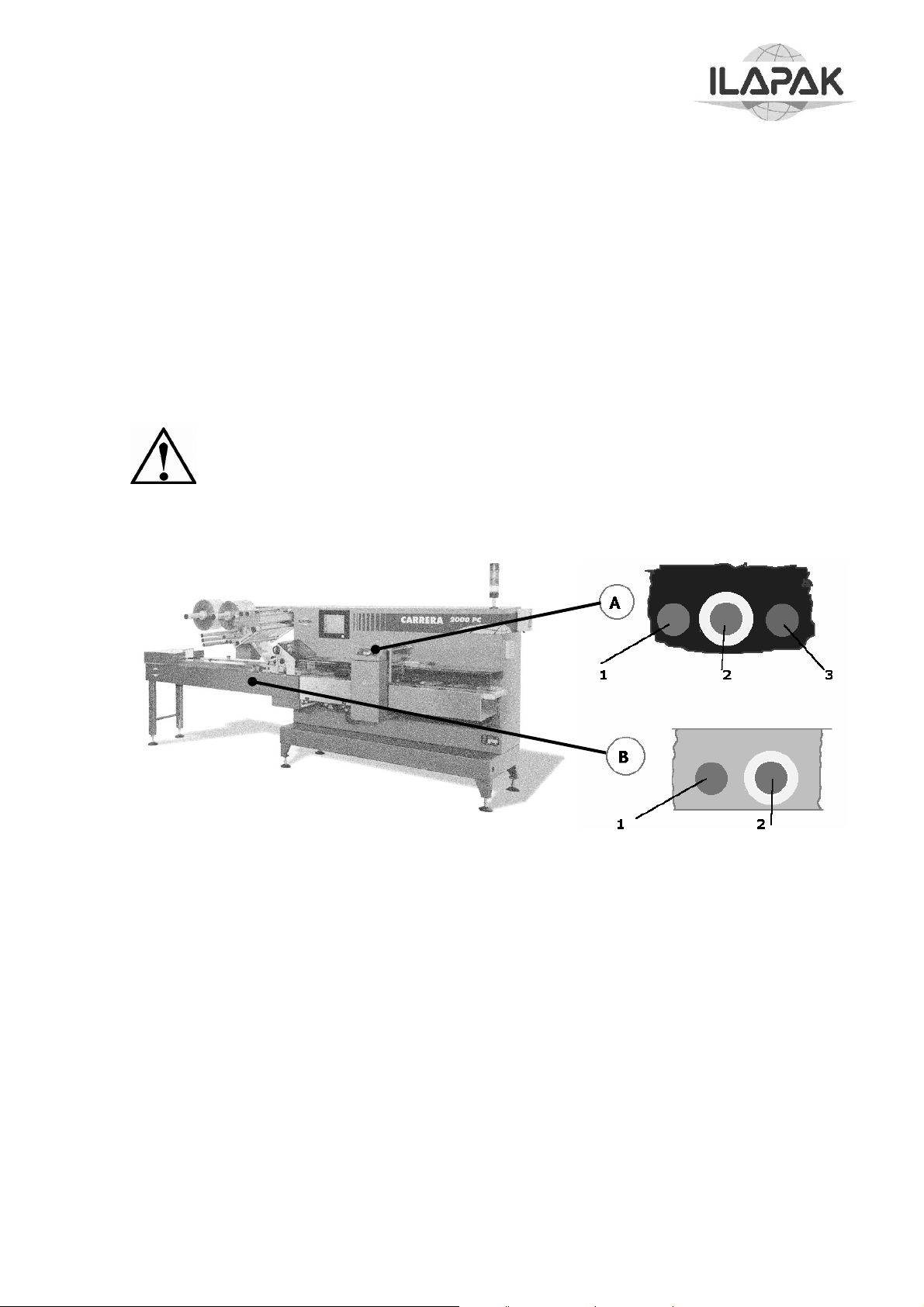
SAFETY DEVICES
The safety devices fitted to the machine are shown in the following picture.
When the safety guards are opened while the machine is in operation, switches stops the
main motor and cuts off the power supply.
When pressed, emergency stop buttons interrupt machine operation and cut off the
power supply.
Isolator switch is a safety device that cuts off electrical power supply to all machine
components when the door of the electrical cabinet is opened.
Copyright ILAPAK Italia S.p.a
Ed 1 Rev 06 - June 2005 PAGE -13
Page 20

T
g
g
Carrera 2000 PC Touch
MACHINE INSTALLATION
INSTALLATION SITE REQUIREMENTS
The machine should be installed on a supporting floor that can bear the weight of the
machine on the several supporting points, without a decline during time; furthermore the
floors should be on spirit level, non-slipping and shouldn’t present roughness
The installation site should allow the operator to go around the machine without any
hindrances and to carry out easily the normal working operations and service operations
(maintenance and interventions on the machine). Furthermore it is extremely important,
that the protection guards and the doors of the electrical power boards can be opened
without hindrance and in a complete way. For this purpose the minimum distance
according to the building walls or to a possible hindrance should be about 2 meters.
EXTERNAL INSTALLATION REQUIREMENTS
The installation site should be prepared for the connection of the electrical installation,
the earthing, the pneumatic installation and possible coolant installation of the machine to
the outside net. The electrical and earthing installation of the installation site should be
realized according to the standards.
UNPACKING
The machine is shipped using packaging or proper protection means according to the
used kind of transport; pay particular attention when unpacking in order to avoid
damages to people or to the machine and to dismantle the packaging materials according
to the legal rules in force in the country where the machine will be used.
At receipt, control visually regarding possible damaging deriving from the shipment or
missing parts.
In case of damaging or missing part, get immediately in touch with the forwarding agent.
MACHINE UNPACKING AND POSITIONING
ATTENTION
he lifting operations of the parts composing the machine should be
carried out by staff in char
drivers, etc.) and with the assistance on the ground by a person in char
with the signalling if the overall dimension of the load doesn’t allow a
sufficient visibility; the staff should be equipped with the necessary
individual accident prevention protections.
The access to the area where the lifting operations are carried out is
forbidden to the staff, who is not in charge with this operation, using the
most proper means (barriers, signs, etc.). The capacity of the used lifting
means should be suited to the mass to be moved; the movement should
be carried out slowly under good illumination conditions and with sufficient
free space to work under safety conditions.
For no reason, the staff in charge with the operations is authorized to pass
under the load or at its proximity. This is valid also for the staff in charge
with the signalling on the ground.
e of these functions (crane operators, truck
e
Copyright ILAPAK Italia S.p.a
Ed 1 Rev 06 - June 2005 PAGE -14
Page 21

Carrera 2000 PC Touch
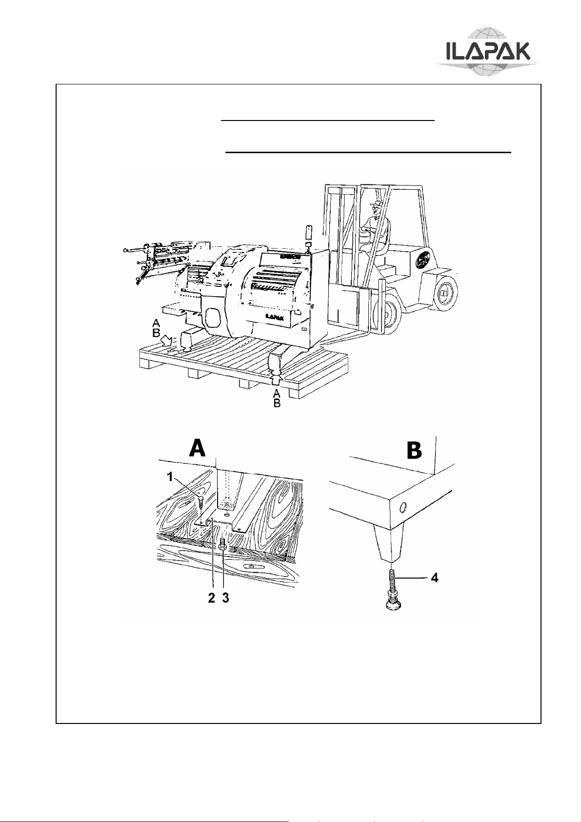
Carefully follow this procedure when unpacking and positioning the machine:
Remove covers and protections, if any from the shipping crate
Remove the infeed conveyor.
By use of suitable equipment , lift the pallet to which the machine is
secured, taking care to operate from the back side in order to avoid any risk
of machine overturning.
Carry the pallet to the location where the machine is to be installed, and
lower it to the ground.
Remove the screws (1) attaching the support channels (2) to the pallet.
Operating from the back of the machine, position the forklift under the base
plate, and lift the machine at a height sufficient to permit pallet removal.
Remove the four bolts (3) that attach the support channels to the machine,
and replace them with the four adjustable feet (4).
Lower the machine to the ground, remove the forklift, and carry out
machine levelling as described in the following paragraph
Copyright ILAPAK Italia S.p.a
Ed 1 Rev 06 - June 2005 PAGE -15
Page 22
A
Carrera 2000 PC Touch
TTENTION: ☺ SCRAP PACKING IN THE FIT DUMP
DON'T LEAVE PACKING IN THE ENVIRONMENT !!
OPERATE FROM BACK SIDE
1. Attachment Screw,
2. Support channel to Pallet
3. Support Channel Attachment Bolt, Support Channel to Machine
4. Adjustable foot
Machine unpacking and positioning
Copyright ILAPAK Italia S.p.a
Ed 1 Rev 06 - June 2005 PAGE -16
Page 23

T
Carrera 2000 PC Touch
WARNING The instructions supplied in this chapter are a synthesis of the procedures
established during the assembling of the machine and are destined to
technical staff, already in possession of the necessary knowledge for this
operation. However the staff should always be accompanied by specialised
ILAPAK staff. The purpose of these instructions is to supply a general
description of the methods, used for the connection of the main groups,
composing the machine.
LEVELLING
The machine has to run in perfect horizontal direction and should transmit only a minor
quantity of possible vibrations on the floor where it is installed; for this purpose, after
having placed it on the operation site, proceed with the levelling acting on the proper
supporting feet on the base and acting on the four adjustable feet, using as reference the
counter plane. At the end of the procedure, block the four feet by means of the related
lock nuts.
WARNING
he levelling of the machine should be carried out with exact precision in
order to avoid torsion phenomenon, an incorrect parallelism of the planes
and unexpected loads on the elements. The constructor declines each
responsibility for damages or malfunctioning of the machine, deriving from
an incorrect levelling or from a missing execution of the established
periodical checks.
Copyright ILAPAK Italia S.p.a
Ed 1 Rev 06 - June 2005 PAGE -17
Page 24
Carrera 2000 PC Touch
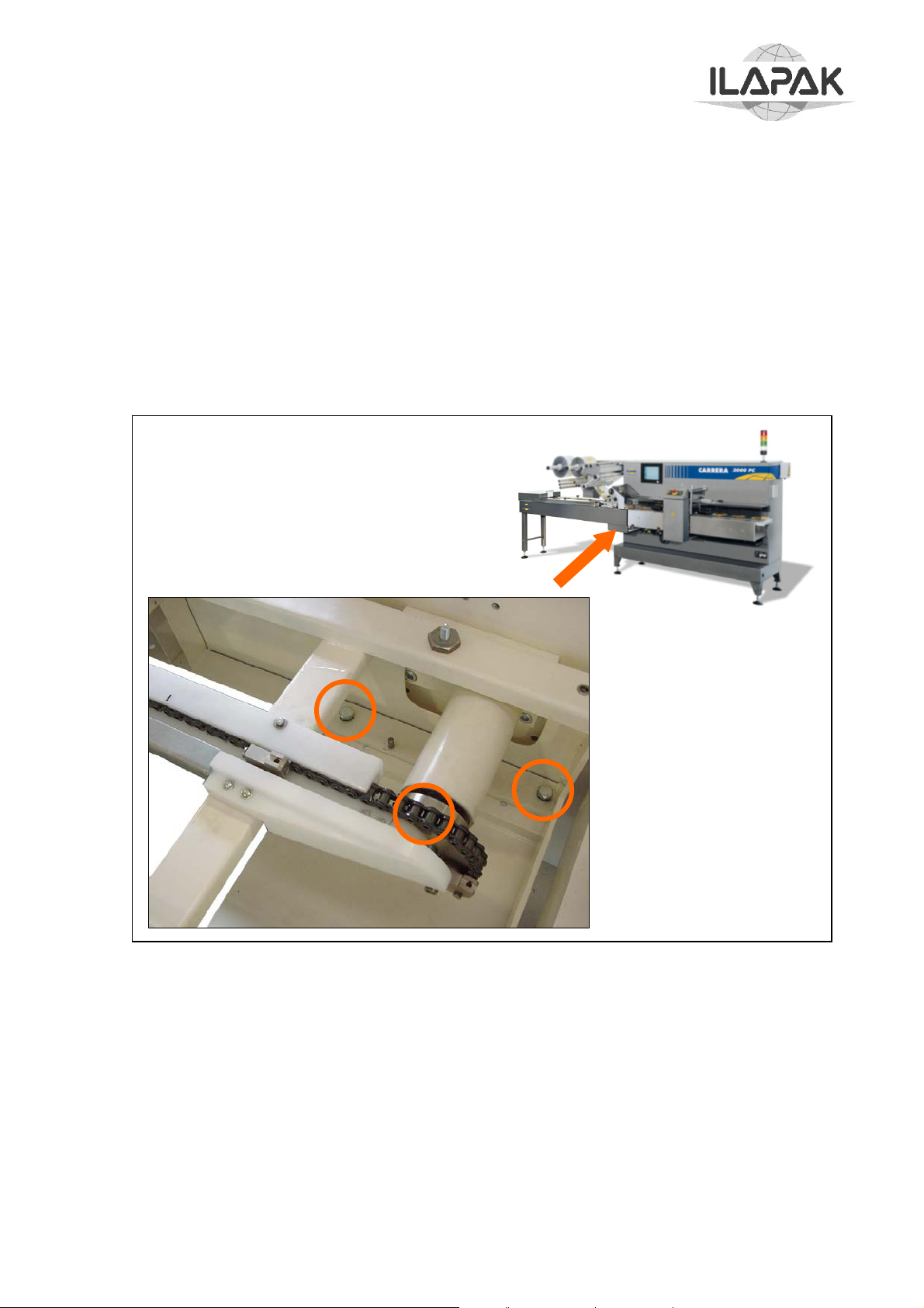
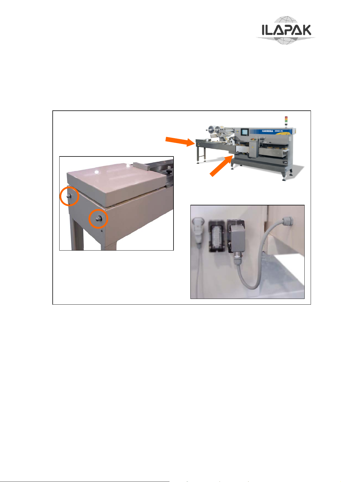
ATTACHMENT OF INFEED CONVEYOR
Attach the infeed conveyor by following this procedure:
Place the infeed conveyor on its support casting on the machine body making
sure that it rests on the casting correctly.
If necessary, level the infeed conveyor by adjusting the two suppor t feet.
Insert the two paper pins for infeed alignment (these pins are supplied with the
machine) then install the four attachment bolts with their washers
Connect the infeed conveyor chain by following the follows procedure:
If necessary, slacken the chain using the two side tensors.
Join the chain ends on the sprocket by use of the special link and the relevant
retaining clips.
Adjust the chain tension by use of the special side tensors, making sure that the
chain is not too tensioned, and that distance “X” measured between the end of
the tensor and the sprocket shaft is the same for both tensors.
Copyright ILAPAK Italia S.p.a
Ed 1 Rev 06 - June 2005 PAGE -18
Page 25
Carrera 2000 PC Touch
CAUTION. A too tensioned chain may result in bending of the sprocket shaft and
damage to the infeed conveyor.
Plug the electrical connector of the auxiliary control panel of the infeed conveyor
into socket on the left (or right) side of the machine
Copyright ILAPAK Italia S.p.a
Ed 1 Rev 06 - June 2005 PAGE -19
Page 26

Carrera 2000 PC Touch
ELECTRICAL SYSTEM CONNECTION
CAUTION:
1. Make sure that the mains power characteristics correspond to those of the
machine.
2. Open the electrical cabinet and connect the power supply wires to the terminal
board by referring to the applicable interconnection diagrams shown in Section
wiring diagrams of this manual.
3. Connect the end of the power supply cable to a mains circuit breaker (thermal
or magnetic) according to the machine connection sequence.
Connection of the machine to the electrical mains power is
carried out by the user under his/her full and sole responsibility,
and in compliance with the following instructions:
EARTHING
The machine should be earthed by means of a centralised line, available on the
installation site. The main earthing joint with the outer line is realized inside the electrical
board.
Copyright ILAPAK Italia S.p.a
Ed 1 Rev 06 - June 2005 PAGE -20
Page 27

Carrera 2000 PC Touch
PNEUMATIC SYSTEM (OPTIONAL)
The machine pneumatic system is designed to the closing of sealing – propelling rollers
In addition to other optional devices such as:
Air gusseting
Air Ejector
Automatic reel splicer
Quality Control
The system is fed directly from the air supply line available at the machine installation
location, through the filter-pressure regulator that is normally set at a pressure of 6-7
bars.
The system is fully controlled by selector valves whose closing and opening is
electronically commanded according to the operating parameters set by the operator.
Each selector valve is also fitted with a pressure regulator that regulates the compressed
air discharge pressure.
COOLANT INSTALLATION CONNECTION (OPTIONAL)
The machine can be equipped with a coolant installation, provided with a specific water
input and output; Check that the water inlet and outlet pipe on the machine are correctly
connected from the distribution block to the users.
CLEANING
Carry out an accurate cleaning of the machine at the end of the installation; remove the
dust and the present residues with particular care to the sliding surfaces. Furthermore
check that there aren’t any oil remnants near the tank of the lubrication installation.
Use a compressed air blowing device and a dry cloth for the cleaning in order to remove
the dust and also a non-aggressive solvent.
Copyright ILAPAK Italia S.p.a
Ed 1 Rev 06 - June 2005 PAGE -21
Page 28

Carrera 2000 PC Touch
MACHINE DEMOLITION
The machine demolition should be performed by staff specialised in the electric and
mechanic field. The standards in force concerning these operations are often different in
the various Countries, so it is recommended to analyse and apply all the provisions stated
by laws at the moment the machine is to be dismissed. The machine has been realised
using non-dangerous materials, (steel, plastics, rubber), which won’t give any problems
for recycling or disposal at the end of the service; anyway, it is necessary to have a deep
knowledge of the machine construction features and great technical skills to disassemble
the machine, besides the specific tools. It is strongly recommended to contact ILAPAK
assistance service, in order to obtain the maximum safety conditions in carrying out this
job.
WARNING It is necessary to provide for the oil recovery and its differentiated disposal
according to the antipollution standards.
Copyright ILAPAK Italia S.p.a
Ed 1 Rev 06 - June 2005 PAGE -22
Page 29

Carrera 2000 PC Touch
MACHINE CONTROLS
PUSH BUTTONS AND OTHER ELECTRO-MECHANICAL DEVICES
Push buttons and switches are located on the console except for the mains isolator switch
on the door of the electrical cabinet on the rear of the machine.
Green push button POWER UP /
With the mains isolator on, powers the machine up or resets power after one of the
following events:
use of the EMERGENCY STOP push button
opening of an interlocked guarding during operation of the machine
mains cut-off
Sets the machine in motion after powering up; in specific conditions executes also the
following functions:
reset an alarm or error message on the display screen
initialises co-ordination (synchronisation) of the “axes” (separate drive motors of
carriage, jaws, product infeed, sealing-propelling rollers and film unwinding roller),
when in a non-synchronised condition.
START
(3)
NOTE: Synchronising of the axes will take place automatically upon pushing
the START button, each time the axes are not any more in their
"normal" positions, in particular after:
turning on the mains;
a mains cut-off;
a size change;
operating one single axis separately;
a film rupture;
operation of the “electronic safety clutch”, i.e. when a product has got caught in the
sealing jaws.
co-ordinated start of all motors (under normal operating conditions); the machine
will accelerate continuously up to the speed set on the speed control potentiometer.
Red push button
makes the machine come to a halt in a pre-defined position with open sealing jaws (so
that the film will not be burnt). Normally, after pushing this button the machine will
reduce speed and approach the correct position at lower speed.
POSITIONAL STOP
(1)
Copyright ILAPAK Italia S.p.a
Ed 1 Rev 06 - June 2005 PAGE -23
Page 30
Carrera 2000 PC Touch
Emergency stop button
Stops the machine with IMMEDIATE effect independent of its momentary position;
In agreement with EC- and other international regulations the operation of the
emergency stop push button has the following effects:
Power off the complete machine;
cut all outputs from the electronic control system;
release compressed air from all pneumatic systems under pressure.
In order to return to working conditions after operating the EMERGENCY STOP button,
it is necessary to unlock it by rotating it in the direction of the arrow.
EMERGENCY STOP
(2)
NOTE: The emergency stop button must not be used other than in case of
real danger or any other emergency situation necessitating an
immediate machine stop.
Using the emergency stop button for “normal” machine stoppages
violates the safety regulations and may lead to damage on the
machine and/or the products to be wrapped.
Copyright ILAPAK Italia S.p.a
Ed 1 Rev 06 - June 2005 PAGE -24
Page 31

Carrera 2000 PC Touch
SIGNAL LAMPS
The signal lamps are located on top of the machine in the form of a “light column” and
are intended to signal different machine conditions which are detailed below:
– red
continuous
EMERGENCY STOP button pushed or guarding opened during machine operation.
Red light remains on until the relative message on the display has been reset.
– orange
flashing
For machines with automatic product indexer: machine in standby mode, i.e. machine
will start automatically upon arrival of products.
– green
continuous
START button pushed, machine in operation and/or drive motors under current.
– orange + green
alternate flashing
Axes not synchronised either after operating one of them alone (operative keys
or JOG keys) or after an operation
of the electronic safety clutch.
– white
continuous
Mains on, i.e. machine under tension.
Red Light
Orange Light
Green Light
White Light
Copyright ILAPAK Italia S.p.a
Ed 1 Rev 06 - June 2005 PAGE -25
Page 32

Carrera 2000 PC Touch
USER INTERFACE
DISPLAY
The display screen is divided into the following main areas:
1
2
5
2
1. Area of machine denomination, selected menu page title and messages
The name of the machine will be indicated under normal operating conditions when
the “Home page” is displayed; the heading of current page will be reported when
other pages of the operating program are displayed, instead.
In the upper area, area delimited by a yellow background, is the actual machine
condition displayed; example: “Delayed start”, Current re-timing”, etc.
NOTE: The interface messages with the user are displayed in this area. If the
message indicates the operation of the EMERGENCY STOP button the cause
of the anomaly that caused the use of the emergency stop should be
attended to first;
only then unlock the EMERGENCY STOP button by pulling it out and reset
the supply by pushing the related button for the electrical line introduction.
3
4
Copyright ILAPAK Italia S.p.a
Ed 1 Rev 06 - June 2005 PAGE -26
Page 33

Carrera 2000 PC Touch
2. Area of “recall buttons”
3. Area of multifunctional keyboard
4. Area of adjustments and data display
This area displays selected menu page with the parameters and their “values”
(i.e. settings); when a parameter is selected, a green flashing LED appears.
5. Area of operative buttons with permanently allocated functions; buttons visible at
all times, which are placed on the left of the interface.
Copyright ILAPAK Italia S.p.a
Ed 1 Rev 06 - June 2005 PAGE -27
Page 34

g
g
Carrera 2000 PC Touch
OPERATIVE KEYS
Deactivated Activated Description
(Optional) Manual opening/closing of pulling roller pair;
activated only while machine is stationary and
deactivated while in operation.
Selection of operating mode (“Manual” or “AUTOMATIC”);
(only in combination with an OPTIONAL automatic product
indexer).
No-product / no-bag: enables and disables the function
which prevents the machine from producing empty bags if
one or more products are missing from the infeed.
(Optional) Its activation makes intervening the by-pass,
diverting the products on arrival.
The by-pass activation interrupts and stops the automatic
feeding linked to the machine.
Active the function “JOG” ( impulse motion)
Moves forward axis “jaws”, in slow motion, independent
from the other motors, activated only with pressed key
and while the machine is stationary
Moves reward axis “jaws”, in slow motion, independent
from the other motors, activated only with pressed key
and while the machine is stationary.
Moves forward axis “product infeed” in slow motion
independent from the other motors; activated only with
pressed key and while the machine is stationary.
Moves at the same time the film unwinding roller, the
itudinal sealing rollers and discharge belt forward in
lon
slow motion independent from the other motors; activated
with pressed key only and while the machine is stationary.
(Optional) It allows to lift the jaws and to carry out the
emptyin
field
of the bags, introducing the related value in the
.
Attention!! This key is enabled with stopped machine only.
Copyright ILAPAK Italia S.p.a
Ed 1 Rev 06 - June 2005 PAGE -28
Page 35

Carrera 2000 PC Touch
MULTIFUNCTIONAL KEYBOARD
Keys for insertion of numerical values.
Key for insertion of sign “–“ (minus) for negative value (– nn).
Key for insertion of sign “.” (full stop, comma) for decimal values.
Keys for changing values by one unit steps.
Key deleting the numerical value entered or, in editing phase, the
product name.
Confirm Key.
Copyright ILAPAK Italia S.p.a
Ed 1 Rev 06 - June 2005 PAGE -29
Page 36

A
Carrera 2000 PC Touch
RECALL KEYS
Key displaying “cover page”.
Key for scrolling forward or backward the pages of the operative
program.
Key displaying “INDEX” page.
Key displaying page with enabling functions and options
Key to display the “Production statistics”.
Help on line
Key to enable the “Help on line”.
ctivating the key and pressing on whatever figure, there will be
activated a “Help” window with a short description of the interested
object, as in the example of the following figure).
Copyright ILAPAK Italia S.p.a
Ed 1 Rev 06 - June 2005 PAGE -30
Page 37

Carrera 2000 PC Touch
PRELIMINARY OPERATION
LANGUAGE SELECTION
Within limits the language of the operator interface can be selected and/or changed.
In order to turn on a different language from the one appearing upon power up proceed
as follows:
1 With key open INDEX page;
Touch key “Service sub-menu”
On the following visualized page
touch key “Language selection”.
Copyright ILAPAK Italia S.p.a
Ed 1 Rev 06 - June 2005 PAGE -31
Page 38

Carrera 2000 PC Touch
4. In the window listing the available languages select the desired language.
Copyright ILAPAK Italia S.p.a
Ed 1 Rev 06 - June 2005 PAGE -32
Page 39

Carrera 2000 PC Touch
USER PASSWORD
The “Master” password (set by manufacturing company) is supplied at delivery of the
machine. It allows to carry out permanent modifications (saving) of the data set in
relation to the various parameters of the operating program and other operations
concerning the deletion, creation, copying and denomination of the products from the
page “Product list”.
The setting of this code also allows the creation of a new user password (to be set
directly by the user and called password “operator” ), and after its setting, it allows to
carry out the same operations which can be executed by means of the “master” password
(included the creation of another new password).
Therefore the main aim of the “master” password is to re-enter the functions protected
by means of the code, in case password “operator” , entered by the user of the machine,
will be forgotten.
The “Master” password should therefore be accessible by the person in charge
of the production, only.
NOTE: Without password the operator is always entitled to changing data
temporarily, however, without memorising them and thus overwriting existing
data.
The following table lists those functions that are accessible with each protection level.
PROTECTION LEVEL ACTIVATED FUNCTIONS
None
Password “Operator”
(defined by the user – initially the code set by
the factory is 3)
Password “Master”
(defined by ILAPAK and can’t be modified
251200)
– Page “PRODUCTS LIST”
load
– Page “PRODUCTS LIST”
save
copy
– exceeds the password “Operator” defined by the
user
– same functions of password “Operator”
, delete , new ,
, edit .
Copyright ILAPAK Italia S.p.a
Ed 1 Rev 06 - June 2005 PAGE -33
Page 40

Carrera 2000 PC Touch
ENTERING THE PASSWORD
Enter the password as follows:
1. With key open INDEX page.
2. Touch key “Service sub-menu”.
3. On page “Service”
touch key “Password access”.
Copyright ILAPAK Italia S.p.a
Ed 1 Rev 06 - June 2005 PAGE -34
Page 41

Carrera 2000 PC Touch
4. With the following window visualized
digit the “Master” password (defined by ILAPAK).or the “Operator” password.
Each entered numeric value will be displayed in the window through an asterisk.
NOTE: In case of typing error, use key to delete the entered password.
5. Confirm the entered code with .
6. With key “<- Back ” open SERVICE page.
Copyright ILAPAK Italia S.p.a
Ed 1 Rev 06 - June 2005 PAGE -35
Page 42

Carrera 2000 PC Touch
DEACTIVATION OF THE PASSWORD
To deactivate the possibility to use the protected functions by the password mode and
resetting the normal use conditions, proceed as follows:
1. With the following window visualized.
touch key “Disabile Password”.
Copyright ILAPAK Italia S.p.a
Ed 1 Rev 06 - June 2005 PAGE -36
Page 43

Carrera 2000 PC Touch
MODIFICATION OF PASSWORD “OPERATOR”
In order to change the existing password “Operator” as follows:
1. With key open INDEX page.
2. Touch key “Service sub-menu”.
3. On page “Service”
touch key “User password change”.
Copyright ILAPAK Italia S.p.a
Ed 1 Rev 06 - June 2005 PAGE -37
Page 44

Carrera 2000 PC Touch
4. With the following window visualized
5. Digit the “OLD PASSWORD”, confirm the entered code with .
6. Digit the “NEW PASSWORD”, confirm the entered code with .
7. Digit the “CONFIEM PASSWORD”, confirm the entered code with .
Each entered numeric value will be displayed in the window through an asterisk.
NOTE: In case of typing error, use key to delete the entered password.
8. Confirm the entered code with .
Copyright ILAPAK Italia S.p.a
Ed 1 Rev 06 - June 2005 PAGE -38
Page 45

Carrera 2000 PC Touch
OPERATION CYCLE START
Make certain that the machine is connected to the compressed air line and that the air
pressure on the manometer of the filter-reducer group is adjusted at a value of 6 bar. If
necessary, act on the regulator.
If the machine is equipped with a water sealing cooling system, make certain that it is
connected to the installation and the related tap is open.
Make certain that the EMERGENCY stop buttons are unlocked.
Introduce the main switch on the back closing board of the electrical cabinet.
1. When displaying the “introduction Page”,
with highlighting the following alarm message
EMERGENCY ON
Main guarding or eventual other auxiliary
guarding open. Close the guarding and, in
case the key switch |GUARDING is
disabled (position 0), press the power ON
pushbutton
push the green POWER button and then touch key
“
Emergency stop
” from the screen.
to reset the alarm message
Copyright ILAPAK Italia S.p.a
Ed 1 Rev 06 - June 2005 PAGE -39
Page 46

Carrera 2000 PC Touch
BASE PAGE
The machine running is confirmed by the display of the following “main” page.
NOTA: All mechanical settings of the machine (provided no changes have been carried
out meanwhile) as well as parameters and values appearing on the various menu
pages refer to this particular product.
If it is intended to continue with this product this is considered a start of Production as
described in paragraph “PRODUCTION”. Though the machine is already set up, it is
nevertheless recommended to check, for safety reasons, the mechanical settings and
compare them to the values on menu pages “Adjustments” and “Dimensions”.
If the product to be wrapped does not correspond to the previous one, however
adjustments and data are in the product memory (the product appears in the “Product
list”) a size change has to be carried out which is described in paragraph “SIZE
CHANGE”.
For a product to be wrapped for the first time (i.e. product data not memorised and
product not appearing in the “Product list”) all values have to be established and a
complete new programming is required. The latter is the object of the following
paragraph
Copyright ILAPAK Italia S.p.a
Ed 1 Rev 06 - June 2005 PAGE -40
Page 47

Carrera 2000 PC Touch
CREATION OF A NEW PRODUCT
Setting the machine up for a completely new product should normally be carried out
either in the manufacturer's place after completing the machine or during commissioning
through qualified personal of the manufacturer or one of his subsidiaries or agents. This
is the way one can be certain that the machine has been set to the best of its possibilities
and provides output and efficiency.
Nevertheless the following sections provides complete information on all aspects of
setting up a "new product" including programming the setting values of the product.
The instructions follow a certain logical sequence, which has proven to be the best way of
obtaining the desired results. The individual steps should therefore be carried out exactly
the described sequence.
database
The first operation of programming a new product is the opening of a new database,
which can be done in two different ways:
A. Creating a new data base based on the “default values”, i.e. the values pre-set in
the program (see the next paragraph)
B. Copying an existing database, (i.e. starting from the values) of a similar previously
programmed product and adjusting them to the new product (see paragraph
products list management)
Copyright ILAPAK Italia S.p.a
Ed 1 Rev 06 - June 2005 PAGE -41
Page 48

Carrera 2000 PC Touch
Creation of a new database
In order to create a new database proceed as follows:
1. Enter user password.
2. With key open INDEX page.
3. Touch key “Product list” to op en page illustrated below.
4. Touch key on page “Product list” to open the new window illustrated below
which prompts entering the denomination of the product being programmed right
now
Copyright ILAPAK Italia S.p.a
Ed 1 Rev 06 - June 2005 PAGE -42
Page 49

Carrera 2000 PC Touch
The default product name proposed by the system consists of “product” followed by a
number corresponding to the next free memory position.
5. If you want to change the default name displayed on the page, digit the new
denomination using the alphabetic and/o numeric keys.
NOTE: If you don’t want to change the denomination, the new created product
will keep the initial default name.
6. After checking for correct spelling confirm with and thus memorise the
product name; the window will close and the new product will appear amongst the
other on the “Product list”.
7. After the following window has appeared
confirm with .
8. After memorising the product name the latter has to be uploaded into the
operational memory.
With keys
and select the newly created product name in the
“Product list”.
Copyright ILAPAK Italia S.p.a
Ed 1 Rev 06 - June 2005 PAGE -43
Page 50

Carrera 2000 PC Touch
9. Touch key ; successful loading of the product is confirmed with the
visualization on the page of the relative message and of the new product name.
This creates the basis for the further programming of the new product. The subsequent
establishing and entering of data is described in the following paragraphs.
Copyright ILAPAK Italia S.p.a
Ed 1 Rev 06 - June 2005 PAGE -44
Page 51

Carrera 2000 PC Touch
MECHANICAL MACHINE ADJUSTMENTS
The mechanical adjustments and configurations to be made to the machine before
production refer to the selected product and are carried out according to its size and
features.
DETERMINING THE STEP OF THE PRODUCT FEED LUGS
The feeding bed chain is equipped with hooks for fixing the product feed lugs.
These hooks are positioned so as to allow the lugs to be mounted in various steps
according to the size of the product to be packed.
The step of the product feed lugs is determined by applying the following formula
P=
where
P = Step of product feed lugs (expressed in chain links)
L = Product length (in mm)
H = Product height (in mm)
S = Thickness of jaws (generally 30 mm)
12.7 = Conversion factor equal to the length of a chain link (1/2”)
For example, for a product that is 160 mm long and 60 mm high to pack on a machine
with standard jaws, the corresponding step will be:
L+H+S+20%H
12,7
(160 +60+30+ (60x20%))/12.7 = 20.63 21
The lug step to use on your machine will be the next highest multiple of the hook step
shown on the technical sheet to the one that has just been calculated.
Let’s continue the example, to pack a product of a size requiring a minimum step of 21
links, a machine with a feeding chain with 1 block mounted every 8 links will require the
correct step to be 24 as this is the next highest multiple of 8 after 21.
NOTE: In case of printed film, the cut pitch (bag length) will be determined by the
distance of the printing notches.
Copyright ILAPAK Italia S.p.a
Ed 1 Rev 06 - June 2005 PAGE -45
Page 52

Carrera 2000 PC Touch
INSERTING THE INFEED LUGS
The height of the infeed lugs is determined by the height of the product whilst their width
is limited by the folding box aperture. After dropping back the lugs have to pass freely
through the latter and must not touch on the folding box base.
In order to insert the lugs at the previously determined pitch it is necessary moving the
infeed chain. This is achieved as follows:
1. Press key infeed forward, until the infeed chain has reached the desired
position;
Upon touching key the infeed chain starts moving immediately (though at low
speed). While the chain is in motion the orange and green signal lights of the
light column will flash alternately.
CAUTION: Move the chain solely the way described above! Do NOT
use the START key for this purpose.
2. Extract the previously used pushers by pulling and holding outwards the spring-loaded
locking pin (3) and, simultaneously, pull the pusher (2) upwards and out from the
carrier block.
3. Insert new pushers (1) into the blocks (2) and make sure pin (3) settles in with an
audible “click”.
1.LUG
2.SUPPORT
3.PIN
Copyright ILAPAK Italia S.p.a
Ed 1 Rev 06 - June 2005 PAGE -46
Page 53

Carrera 2000 PC Touch
Fixed Folding box
The fixed folding box is constructed on size for each determined products. The possibility
to wrap a product using an already existent folding box depends first of all on its physical
dimensions and then on the requirements of the wrapping (in particular the film timing).
The guides of the folding box (tunnel) are provided with holes for a limited width
adjustment. These adjustments serve essentially to optimise the operation of the folding
box and not to suit it to the product width.
For the assembling of the fixed folding box, proceed as follows:
1. Position the rear plate and the front plate (1) one after the other onto the fixed bolts
of the conveyor support and fix them by means of the locking handles (2).
NOTE: Make certain that the points of the folding box are perfectly centred among the
film pulling rollers.
2. Make sure that the internal guides (3) are parallel and that the product to be packed
runs smoothly.
3
12
Copyright ILAPAK Italia S.p.a
Ed 1 Rev 06 - June 2005 PAGE -47
Page 54

Carrera 2000 PC Touch
Adjustable Folding Box (Optional)
For the assembling of the adjustable folding box, place it on the fixed bolts of the folding
box support and block it with the knobs (3), in an analogous way to the fixed folding box.
ATTENTION: The width adjustment of the adjustable folding box is in relation to
physical limits as follows:
– maximum product width = 220 mm
For the adjustments “A”, “B”, “D” and “C” of the adjustable
folding box (to display the icons, it is necessary to introduce the number “0” according to
the fixed folding box in page “Manual adjustments”) there aren’t any fixed rules; it is
recommended to start from the adjustments of an already tested product with similar
dimensions and to modify the adjustments according to the necessity.
C
A
D
B
Copyright ILAPAK Italia S.p.a
Ed 1 Rev 06 - June 2005 PAGE -48
Page 55

Carrera 2000 PC Touch
Adjusting Product guides
1. Loosen the knobs (2) and move the feeding product guides (1) towards the
outside.
2. Place two products on the conveyor belt: one partially in the folding box and the
other at the end of the folding box well centred with the feeding axis.
3. Place the guides (1) near the products and lock the knobs (2)
N.B.: Make sure that the guides are equidistant from the centre of the feeding chain.
To make it easier for the product to move onto and along the feeding bed, the
guides can be slightly wider towards the outside of the bed. Also make sure there
is no step between the guide and the tunnel of the conveyor against which the
product could jam
1
2
Copyright ILAPAK Italia S.p.a
Ed 1 Rev 06 - June 2005 PAGE -49
Page 56

Carrera 2000 PC Touch
DETERMINING THE WIDTH OF THE REEL
The kind of film reel used must be defined according to its width, the value of which is
calculated as follows:
2 x (product width + product height) + 40 mm
MOUNTING FILM REELS
- Loosen the front reel locking cone (1) and turn the handle (2) anti-clockwise until the
retainer (6) leaves its housing (4).
- Turn the front reel locking cone (1) clockwise by about 90° to allow the retainer (6) to
pass through the hole (5) in the cone
- Pull the front reel locking cone (1) off the roller (3)
- Insert the reel on the roller (3)
- Replace the front locking cone (1) by passing the retainer (6) through the hole (5) of
the cone
- Turn the cone anti-clockwise by about 90° to allow the retainer (6) to be placed in the
housing (4) of the cone
Lock the reel by turning handle (2) and check it is installed correctly.
1
364
2
5
Copyright ILAPAK Italia S.p.a
Ed 1 Rev 06 - June 2005 PAGE -50
Page 57

T
Carrera 2000 PC Touch
INSERTING FILM
WARNING:
AKE CARE TO AVOID GETTING BURNT IF THIS
PROCEDURE IS CARRIED OUT WITH HOT SEALING
ROLLERS
WARNING
OPERATE ON THE MACHINE ONLY WITH MACHINE
STOPPED, WITH EMERGENCY BUTTON PRESSED
1. After mounting the reel, unwind the film onto the take up rollers as shown in the
diagram on the relative plate.
NOTE:
The film unwind change for machine version (left or right) and for film type. For
this reason this is an approximate picture. For a right film unwind refer to the film
unwind label fixed on the machine
2. Open the drive rollers with key
3. Insert the film among the folding box wings and guides.
4. Take the film from the conveyor output and pull out the edges from the conveyor exit
to insert them into the drive and sealing rollers.
5. Close the drive rollers
, making certain that the film remains well stapled
among both edges.
.
Copyright ILAPAK Italia S.p.a
Ed 1 Rev 06 - June 2005 PAGE -51
Page 58

Carrera 2000 PC Touch
ADJUSTING THE MECHANICAL ARM
Adjust the positions of the adjustable lever (1) and tensor roller (3).
To adjust lever (1) move control (2) while to move take up roller (3) use controls (4) and
(5).
When programming a new product, the “X” and “Y” values shown on the
memo page are correctly defined when the film, in the section between the take up roller
(3) and the conveyor (2), forms an upside-down “U”.
NOTE: Correct machine operation depends on the correct position of the film in the
conveyor and on the elimination of any tension irregularities or bending.
2
3 1
Copyright ILAPAK Italia S.p.a
4
5
Ed 1 Rev 06 - June 2005 PAGE -52
Page 59

Carrera 2000 PC Touch
ADJUSTING THE FILM REEL BRAKE
The reel brake may be adjusted by tightening or loosening the hand wheel 1.
N.B.: Increase or decrease braking according to the width of the film reel installed: the
wider the film the greater the braking.
1
Copyright ILAPAK Italia S.p.a
Ed 1 Rev 06 - June 2005 PAGE -53
Page 60

Carrera 2000 PC Touch
JAW HEIGHT ADJUSTMENT
(for machines without related adjustment servomotor)
Version “CARRERA 2000 PC 400”
The selection of the jaw height ensures that transverse sealing is positioned as required
for the height of the product to be wrapped.
Before carrying out this selection, make sure that the electrical power supply is
disconnected.
Loosen the two screws (1) that lock the jaw assy.
Rotate the handwheel (2) to change jaw height by referring to the millimetre rule (3) and
as required to attain a position corresponding to approx. Half the height of the product to
be wrapped.
Tighten the screws (1), and write down the jaw height data in the product chart.
1 1
3
1. Jaw assy locking screws
2 Jaw height adjustment
2
handwheel
3 Millimetre rule
Jaw height selection
Copyright ILAPAK Italia S.p.a
Ed 1 Rev 06 - June 2005 PAGE -54
Page 61

Carrera 2000 PC Touch
Version “CARRERA 2000 PC 250”
The selection of the jaw height ensures that transverse sealing is positioned as
required for the height of the product to be wrapped.
Before carrying out this selection, make sure that the electrical power supply is
disconnected.
Loosen the three bolts (1—3-4) that lock the jaw support plate
Rotate the screw (2) to adjust jaw height by referring to the millimetre rule to
attain a position corresponding to approx. Half the height of the product to be
wrapped.
Tighten the four bolts (1-3-4-), and write down the jaw height data in the product
chart.
3
4
Jaw height selection
2
1
1 Right locking bolt
2 Jaw height adjustment screw
3 Left locking bolt
4 Lower locking bolt
Copyright ILAPAK Italia S.p.a
Ed 1 Rev 06 - June 2005 PAGE -55
Page 62

Carrera 2000 PC Touch
MOUNTING THE INTERCHANGEABLE PRODUCT SUPPORT
Consult the Product Sheet to identify the required product support and mount as follows:
1. Make sure the machine is in the “in phase stop” position (jaws open). If not, move it
by pressing the green start button and then the red in-phase stop button .
2. Position the interchangeable product support (1) and fix with the two screws (2) to
the shaft of the lower jaw (3).
If the type of support to use has not yet been defined (for example during the new
product programming phase), the diameter may be determined as follows:
Diameter = jaw centre to centre distance - product height
After completing mechanical adjustments, the configured parameters concerning the new
product must be saved.
Copyright ILAPAK Italia S.p.a
Ed 1 Rev 06 - June 2005 PAGE -56
Page 63
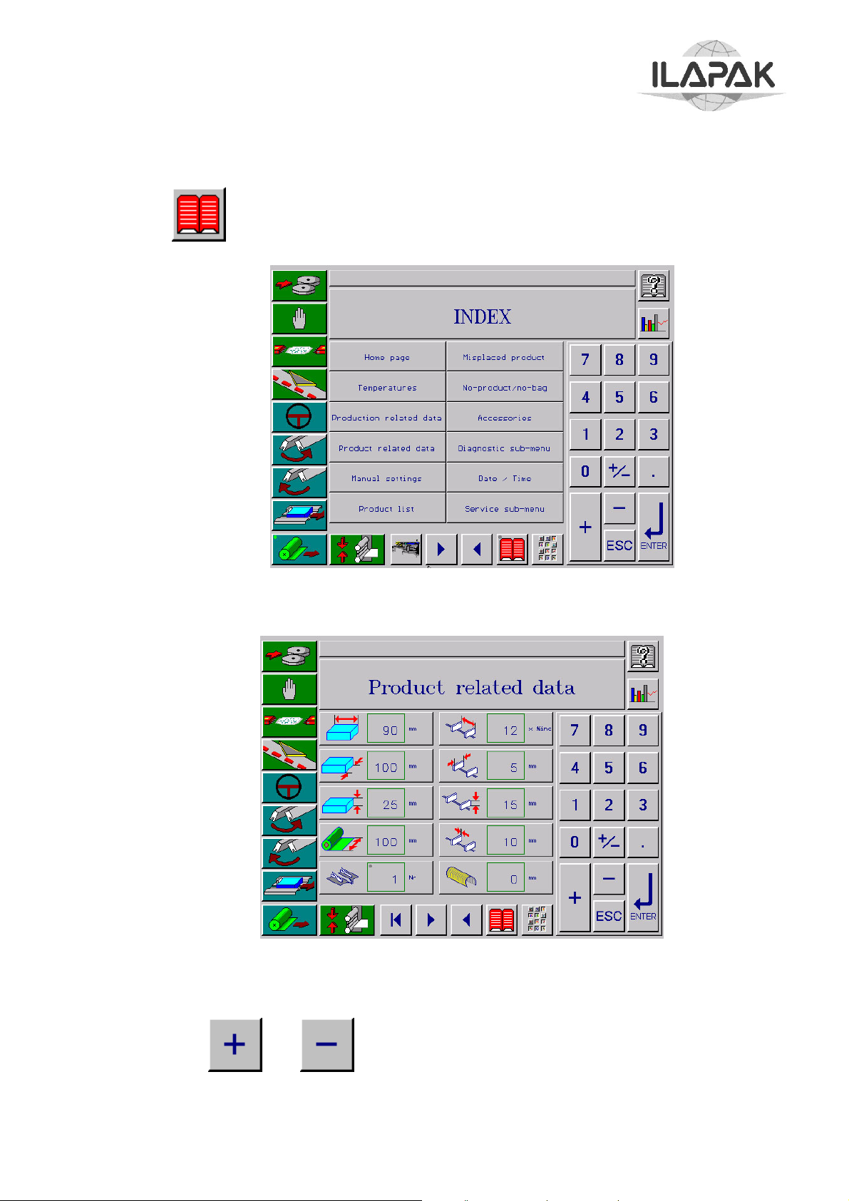
Carrera 2000 PC Touch
ENTERING PRODUCT DIMENSIONS AND ADJUSTMENTS
With key open INDEX page.
Touch key ‘Product related data’ to display the following page.
Press the keys in relation to the dimensional data fields and introduce the new values.
Use the keys
value for big modifications, using the keys of the numerical pad.
Copyright ILAPAK Italia S.p.a
and for small modifications, while key in directly the desired
Ed 1 Rev 06 - June 2005 PAGE -57
Page 64

Carrera 2000 PC Touch
NOTE: At the end of each introduction, confirm the just entered parameter by
pressing key .
NOTE: The fields in relation to the dimensions of the reel band, the folding box, the
product support and the product feed lugs are as a memo only:
Film reel width.
Folding box number
Pusher width.
Pusher Height.
Pusher Thickness.
Product Support.
While the following parameters have to be compulsorily entered since they are
requested by the electronic control system for the synchronisation of the axles:
Product length.
Product width (only in case, where the cardboard placer device has been
installed) .
Product height (only for machines with servomotor for the jaw height
adjustment).
After having entering all the data of this page, press key
Lug pitch.
to pass to the following
page or press key ‘Manual settings’ to pass to page “MAIN INDEX”.
Copyright ILAPAK Italia S.p.a
Ed 1 Rev 06 - June 2005 PAGE -58
Page 65

Carrera 2000 PC Touch
Press the keys in relation to the manual settings fields and enter the new value, always
using the keys and for small modifications or keying in directly the desired
value for big modifications by means of the numerical pad.
NOTE: At the end of each introduction, confirm the just entered value by pressing key
.
Press the area “X” and enter the value in degrees in relation to the
oscillating lever inclination of the reel holder; enter in the area “Y” a value in mm in
relation to the position of the tensor roll.
If you work with an adjustable folding box in the fields “A”, “B”, “C” and “D”
enter the values expressed in mm.
Copyright ILAPAK Italia S.p.a
Ed 1 Rev 06 - June 2005 PAGE -59
Page 66

Carrera 2000 PC Touch
Only for machines without servomotor for the jaw height adjustments: enter the value in
mm in relation to their position .
WARNING: After having entered the value in relation to the product height, make
certain to carry out the jaw height adjustment, as described in section:
MECHANICAL SETTINGS OF THE MACHINE”.
If there is installed a mechanical blowing device, enter the value in mm in relation to the
depth of the pneumatic blowing device nozzles and the value
connected with the nozzles position of the pneumatic blowing device
After entering all data return to BASE page by touching key or repeatedly.
Copyright ILAPAK Italia S.p.a
Ed 1 Rev 06 - June 2005 PAGE -60
Page 67

Carrera 2000 PC Touch
ENTERING THE OPERATING PARAMETERS OF THE MACHINE
While entering the operating parameters of the machine it is necessary to move between
different menu pages.
Those pages can either be opened by scrolling with keys and or touching
the related key on INDEX page
Information on specific accessories, which may be fitted to the machine but are not
mentioned in this section, can be found in the manufacturers' documentation for the unit
in question.
Copyright ILAPAK Italia S.p.a
Ed 1 Rev 06 - June 2005 PAGE -61
Page 68

Carrera 2000 PC Touch
“TEMPERATURE” PAGES
The set temperatures (delimited area by the green frame) are displayed in the first
column of the page, while the actual detected temperatures by the probes are displayed
in the second column.
The warning lights in the column on the right indicate the condition of the resistances
(the blinking in the yellow colour indicates that the resistances are in heating phase).
Temperature first hot rollers pair.
Temperature second hot rollers pair.
Temperature third hot rollers pair.
Temperature lower jaw.
Temperature upper jaw.
Set temperature to 20°C to suppress all the alarm
conditions in relation to the temperatures.
During the creation of a new product, there can be applied some established values for
the displayed parameters, for the same kind of film used for other products, which are
already stored in the program.
Copyright ILAPAK Italia S.p.a
Ed 1 Rev 06 - June 2005 PAGE -62
Page 69

Carrera 2000 PC Touch
To carry out modifications of the displayed values, proceed as follows:
– Press the keys in relation to the values field to be modified.
Use the keys and for small modifications, while key in directly the
desired value for big modifications, by means of the keys of the numeric pad.
NOTE: At the end of each introduction, confirm the just entered parameter pressing key
.
Make certain that the heating phase is activated (enabled functional key ).
NOTE: A safety circuit stops the machine from being started erroneously before the
heating elements have reached the set temperatures;
Should it, nevertheless, be necessary to run the machine while the heaters are
not up to temperature yet, the safety circuit can be bypassed by deactivating
the functional key .that allows the disabling of the temperature alarm
conditions.
At the end of the machine running phase out of temperature limits make certain
to re-activate the functional key
in order to re-activate the safety circuit
and the temperature alarm conditions.
Copyright ILAPAK Italia S.p.a
Ed 1 Rev 06 - June 2005 PAGE -63
Page 70

Carrera 2000 PC Touch
“TEMPERATURES ACCORDING TO THE MACHINE SPEED
If in page “Special functions” is activated the functional key alternatively to the
previous page of the temperatures, the following page is displayed which allow the
programming of the automatic temperatures control of the sealing groups according to
the production speed of the wrapping machine.
The automatic control function is based on the values, detected from the established
temperature curves for each sealing group.
The temperatures curves are set defining the extreme points “t1” and “t2”, which
represent respectively the optimal heating values of the related sealing group to the
minimum and maximum production speed of the wrapping machine.
Only as information is represented in the following graphics, a temperature curve of the
sealing group, applying to point “t1” the value of 115 °C for a minimum speed of 90
pieces/minute, to point “t2” the value of 140 °C for a maximum speed of 140
pieces/minute.
The related excellent temperature value, pre-established by the curve will be
automatically selected with activated automatic control function, for each production
speed modification of each sealing group.
°C
160
150
140
130
120
110
100
90
80
t1
90
ppm
100
ppm
110
ppm
120
ppm
130
ppm
140
ppm
t2
Pz/min
Copyright ILAPAK Italia S.p.a
Ed 1 Rev 06 - June 2005 PAGE -64
Page 71

Carrera 2000 PC Touch
For the definition of the points “t1” and “t2” proceed as follows:
Press key
Using the numeric pad, enter the parameter field
a quite low value representing a minimum
production speed of the machine and confirm the entered value with key
. Then set
in each displayed parameter on the page an excellent temperature value, defined in
testing phase according to the used kind of film and to the established minimum speed.
Confirm each set value with key .
Then press key and enter the parameter field
a maximum production speed value of the machine
Confirm the entered value with key .
Then set in each displayed parameter on the page an excellent temperature value,
defined in testing phase according to the used kind of film and to the established
maximum speed. Confirm each entered value with key .
After making certain of the correct entered values, press key to start the
automatic temperatures control phase and carry out the saving of the parameters.
NOTE: To deactivate the automatic temperatures control of each sealing group in
relation to the production speed of the machine, deactivate the related
functional key .
Copyright ILAPAK Italia S.p.a
Ed 1 Rev 06 - June 2005 PAGE -65
Page 72

Carrera 2000 PC Touch
PAGE “PRODUCTION RELATED DATA”
This page allows the entering of the production data in relation to the operation of the
machine. During the entering phase of a new product, it is compulsory to enter the data
regarding the film tensioning, the length of the desired wrapping bag en the maximum
speed the machine can reach during the phase production.
For the meaning and the setting of the other data in relation to the settings, which have
to be carried out during the running of the machine, see the instructions of the next
paragraphs.
Product – to bag
centring
Print - to bag
centring
Web tension
Bag expelled in
empty mode with
jaws open
Lug Position
Jaw speed
compensation
Cut-off length
(or register spot
pitch)
Max. adjustable
machine speed
Off Set parameter
Jaws angle open
To introduce the parameters necessary for the running of the machine, observe the
following instructions:
parameter in relation to the bag length.
NOTE: The theoretical film cut-off length calculated according to the formula
(L + H + S) + 10%
or, if panel printed, registered film is used, the pitch of the print registration
marks measured over several pitches.
Introduce the bag length value; use the keys and for small modifications
and key in directly the desired value for big modifications by means of the pad keys.
Copyright ILAPAK Italia S.p.a
Ed 1 Rev 06 - June 2005 PAGE -66
Page 73

Carrera 2000 PC Touch
NOTE: At the end of each introduction, confirm the just entered parameter pressing
key .
parameter in relation to the maximum speed; enter the related
value proceeding as described in the previous point.
NOTE: For each product the maximum permissible speed can be programmed in order to
avoid running the machine too fast by for the given seal temperatures and thus
producing poor seals.
The set value represents the maximum speed value that can be entered in the
Home page.
. Parameter related to the film tensioning; introduce an already
established value for a product similar to the one that is being wrapped.
NOTE: In the absence of any other value it is advised to start with the default value of
2 kg.
Copyright ILAPAK Italia S.p.a
Ed 1 Rev 06 - June 2005 PAGE -67
Page 74

Carrera 2000 PC Touch
Off Set Parameter
The sealing jaws and the film of the wrapping should have the same speed during the
length of their meeting, in order to obtain a correct transversal sealing.
The PC of the machine will automatically calculate the sealing phase, according to the
product data and the machine data.
However, in case of very tall products, the jaws can intercept the film before having
equalized their speed to the speed of the film, thus causing a breaking.
In this case it is possible to modify the starting point of the sealing phase, by operating in
the following way:
On page “”Production related data”
enter a small variation to the value quoted in field
by means of the keys
or and confirm with key .
NOTE: This field can only be displayed upon entering of the user’s password
Wrap some products at an average speed and check that the problem has been
solved. If necessary, carry out some further value changes in field .
NOTE: The Off Set parameter is very important for the correct working of the wrapping
machine.
Therefore, if some other production problems should be verified as a result of
the executed changes, get in touch with the ILAPAK servicing.
Copyright ILAPAK Italia S.p.a
Ed 1 Rev 06 - June 2005 PAGE -68
Page 75

Carrera 2000 PC Touch
“ACCESSORIES” PAGE
Press key to display Index page.
Press key “Accessories” to display the following page.
The page showed above is merely indicative, as it may vary based upon the number and
type of accessories installed on your machine.
The display of the pages called in the following paragraphs can be performed by calling
directly the desired page through the relevant key on the above mentioned page and,
subsequently, by pressing key and , in order to scroll the various pages.
For the parameter setting, it is possible to start the machine at low speed or in “JOG”
mode and to detect the enabling/disabling position in the box indicating current position,
transferring then the value into the relevant fields.
For the data input, proceed as follows:
- Press the key of the value to be changed in relation to the required function.
- For little changes, press keys and , while for great changes, input
directly the desired value using the keys of the numeric key pad.
- At the end of each operation, confirm the last input parameter by pressing key
.
Copyright ILAPAK Italia S.p.a
Ed 1 Rev 06 - June 2005 PAGE -69
Page 76
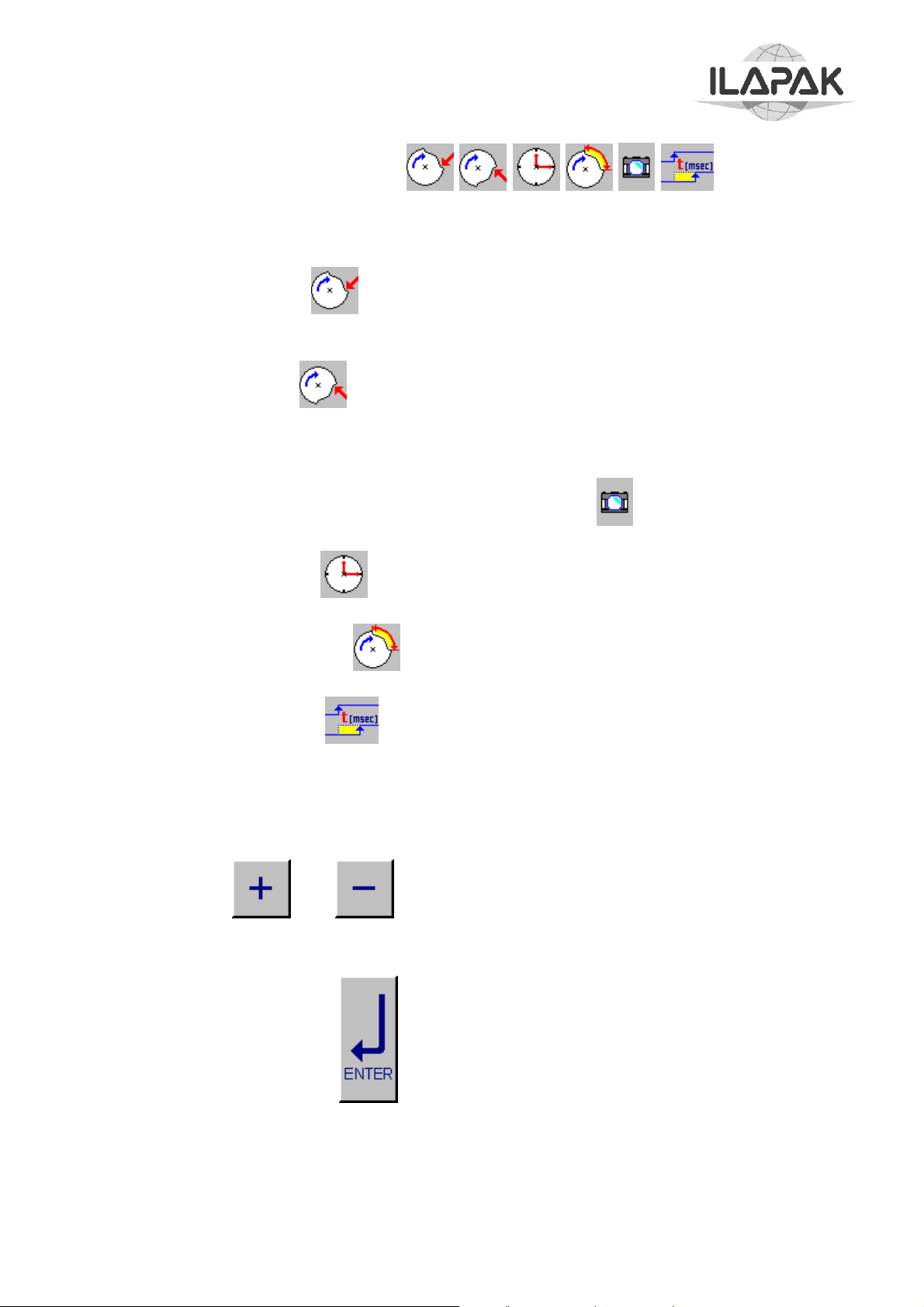
Carrera 2000 PC Touch
Description of parameters
The various functions of the operation parameters in relation to the different accessories
devices, which can be installed on the machine, are described in this page.
In the column “Start” are set the values in degrees of a virtual machine cycle,
which determine the point where the activation of the device should start.
In the column “Stop” are set the values instead, which determine the point of the
machine cycle where the operation of the device is deactivated.
The value “Actual” of the machine phase (machine cycle degrees) is displayed in the
first column of the page linked to the image of the camera .
The parameter “Time” defines the duration, expressed in millisecond, of the
optional activation.
The parameter “Duration” defines the duration, expressed in degrees, of the
optional activation.
The parameter “t/msec” allows the entering of a value that defines and advanced
intervention of the option according to the set value in parameter “Start” en is generally
used during production phase at high speed.
To introduce the data proceed as follows:
– Press the key of the value to be modified in relation to the requested function.
Use the keys and for small modifications and key in directly the desired
value for big modifications, by means of the numeric pad.
NOTE: At the end of each introduction, confirm the just entered parameter by
pressing key .
Next are described the most common functions used on the machine. For the settings of
the parameters in relation to other accessories, refer to the specific technical
documentation.
Copyright ILAPAK Italia S.p.a
Ed 1 Rev 06 - June 2005 PAGE -70
Page 77

Carrera 2000 PC Touch
ACCESSOIRES PAGE: PRINTER/GUSSET/CARDBOARD CUTTER
Printer
Signal (impulse) to control a printer device at the outside.
Program the parameters “Start” and “Stop” as requested to obtain that the print marking
appears on the desired point.
The control sign (not the marker device) can be activated or deactivated by means of the
related functional key .
Gusset
The related parameters “Start” en “Stop” determine respectively the activation an d the
deactivation of the pneumatic gusset assembled on the transversal sealing group.
In order to enable the operation of the pneumatic gusset, activate the related functional
key
Program the parameters “Start” and “Stop” in relation to the characteristics of the product
to be wrapped.
Copyright ILAPAK Italia S.p.a
.
Ed 1 Rev 06 - June 2005 PAGE -71
Page 78

Carrera 2000 PC Touch
Cardboard cutter
Signal (impulse) for the control of a cardboard cutter device
Program the parameter “Start” to carry out the cutting of the cardboard in such a way to
time the device with the feeding of the wrapping machine.
The cardboard cutter device can be activated or deactivated by means of the related
functional key .
Independent cut
Signal (impulse) for the control of the independent cutting blade. Program the parameters
“Start” and “Stop” as requested in order to obtain that the blade can cut and divide the
just produced bags.
Attention Set the start value at 179° and stop at 181°. Only in case where the device
can’t cut the film, modify the values of 1° (start 178°, stop 182°)
The advance of the blade out-coming can cause breaking of it.
Set both values at 0° to wrap the bags without the help of the accessory device.
Copyright ILAPAK Italia S.p.a
Ed 1 Rev 06 - June 2005 PAGE -72
Page 79

Carrera 2000 PC Touch
ACCESSOIRES PAGE: LABEL APPLICATOR/SPRAY
Label applicator
The related parameters “Start” and “Delay (t/msec)” determine respectively the activation
and the anticipation of the label applicator device intervention.
To enable the operation of the label applicator, activate the related functional key
Spray
The related parameters “Start” and “Stop” determine respectively the activation and the
intervention time of the spray device.
To enable the operation of the pneumatic blowing device, activate the related functional
key.
The parameter allows selecting the intervention of the device on
the products.
Copyright ILAPAK Italia S.p.a
Ed 1 Rev 06 - June 2005 PAGE -73
Page 80

Carrera 2000 PC Touch
Various accessory pages
Following are showed the pages of the most frequently accessories used on the
machines.
For the setting of the parameters of the accessories installed on your machine, make
reference to the technical explanation in Section “Accessories” of this manual.
Device name
Operating
parameters
Copyright ILAPAK Italia S.p.a
Ed 1 Rev 06 - June 2005 PAGE -74
Page 81

Carrera 2000 PC Touch
"USER CAMS" PAGE
The page “User cams” allows the programming of four independent main cams, which
can be used for the control of the peripheral unit installed on the machine a/o on the
auxiliary appliances.
The operation of the cams can be synchronized with one of the reference axles (feeding
axis, film axis, jaw axis) , which angular position (expressed in degrees of a virtual
machine cycle) is displayed in the lower page part.
Furthermore, according to the requirements, the duration of the operation of each main
cam can be configured both according to an established angle of the machine cycle, as
well as according to a fixed established time.
– The parameter “Start” defines the position (referred to a point of the
machine cycle) where the option operation has to be activated.
– The parameter “Stop” defines the position (referred to a point of the
machine cycle) where the option operation has to be deactivated.
NOTE: This parameter can be displayed only when the next parameter “Temp”
is set to zero.
- The parameter “Duration”
the optional activation.
Copyright ILAPAK Italia S.p.a
defines the duration, expressed in degrees, of
Ed 1 Rev 06 - June 2005 PAGE -75
Page 82

Carrera 2000 PC Touch
– The parameter “Time” defines the duration, expressed in millisecond, to
activate the option.
NOTE: If this parameter is set, the program eliminates automatically the
previous “Stop” parameter.
– The parameter “Sincr.” defines the axis where the optional operation is
synchronized for the positions Start and Stop:
–
1 = feeding motor axis
2 = film unwinding motor axis
3 = jaw motor axis
– The parameter “t/msec” allows entering a value, that defines an
advanced intervention of the option regarding the set value in the parameter
“Start” and is generally used in production phase at high speed.
Programming procedures
NOTE: Press on the related field for the setting of the parameters and enter the value
using the numeric pad or the keys and . Confirm each entered
value by pressing key .
Press on the related field to parameter “Sincr.” and enter the number
corresponding to the axis, where the cam should be synchronized.
Adjust the speed to the minimum value and start the machine pressing the button
START.
When the position of the machine cycle is obtained, where the optional operation has to
be activated, detect the value in degrees noted in the field in relation to the position of
the reference axis where the cam has been synchronized. Then stop the machine.
Press on the field in relation to parameter “Start” and enter the value detected in
the previous point.
Copyright ILAPAK Italia S.p.a
Ed 1 Rev 06 - June 2005 PAGE -76
Page 83

Carrera 2000 PC Touch
Operation duration according to a machine cycle angle
Adjust the speed to the minimum value and start the machine pressing the button
START. When the position of the machine cycle is reached, where the optional function
should be deactivated detect the value in degrees noted in the field in relation to the
reference axle where the cam has been synchronised. Then stop the machine.
Press on the filed in relation to parameter “Stop” and enter the value detected at
the previous point.
Operation duration in relation to an established fixed time
Press on the field in relation to the parameter “Time” and enter a value expressed
in millisecond representing the optional operation duration.
The parameter “t/msec” has to be set next, after the start of the production
phase and whenever a delay of the function controlled by the cam consequently to an
increase in the speed of the machine is detected.
If necessary, observe the same listed procedures, it is possible to program a second cam
completely independent from the first one.
Then enable the operation of the accessory device linked to “User cam 1” or “User cam 2”
or “User cam 3” or “User cam 4” activating the respectively functional keys ,
in page “Special functions – 2” .
Copyright ILAPAK Italia S.p.a
Ed 1 Rev 06 - June 2005 PAGE -77
Page 84

g
Carrera 2000 PC Touch
PAGE “FUNCTIONS”
On this page, displayed by means of the recall key , are the keys related to the
activation or the deactivation of the options present on the machine.
The functions enabled to operation depend on the options installed on the machine;
following you can find a complete list of the available functions and their related
associated keys.
Deactivated Activated Description
Activates/deactivates the error alarm message emitted by
an external accessory device; programmable.
Activates/deactivates the error alarm message emitted by
an external accessory device; programmable.
Activates/deactivates the error alarm message emitted by
an external accessory device; programmable.
Activates/deactivates the error alarm message emitted by
an external accessory device; programmable.
Suppresses the alarm “Error lug pitching” and permits
operatin
the machine while infeed lugs are missing or
badly positioned.
Copyright ILAPAK Italia S.p.a
Ed 1 Rev 06 - June 2005 PAGE -78
Page 85

Carrera 2000 PC Touch
Deactivated Activated Description
Activates/deactivates the pneumatic gusseting device
Activates/deactivates the user-programmable cam #1
for the running of the external accessory devices.
Activates/deactivates the user-programmable cam #2
for the running of the external accessory devices.
Activates/deactivates the accessory printer device
Activates/deactivates the accessory cardboard cutter
device.
Suppresses the alarm in relation to the temperature of the
sealing groups (rollers and jaws)
Activates/deactivates the accessory label applicator
device.
Activates/deactivates the automatic film reel splicer device
Activates/deactivates the photocell system (product
safety) detecting misplaced products.
Stops jaws from closing when detecting product(s) within
the area destined to the transverse seal and thus avoids
damaging products and dirtying sealing jaws.
Activates/deactivates the back seal trim suck off device –
Activates/deactivates the control quality device
Activates/deactivates the accessory automatic feeder
device
Activates/deactivates the accessory sprayer unit device
Activates/deactivates the print registration system for
printed film
Copyright ILAPAK Italia S.p.a
Ed 1 Rev 06 - June 2005 PAGE -79
Page 86

Carrera 2000 PC Touch
Deactivated Activated Description
Activates/deactivates cam operation for the reference
signal to an external label applicator device
Activates/deactivates cam operation for the reference
signal to an external label applicator device
Activates/deactivates the heating system of the jaws and
sealing rollers
Activates/deactivates the ‘Temperatures according to the
machine speed’.
Activates/deactivates the hic-up function mode
Activates/deactivates the external label applicator alarm
signal
Activates/deactivates the programmable cut function
mode
Activates/deactivates the “product on lug control” -
Activates/deactivates the motorised bars product support -
Activates/deactivates the Indy suck off device
Activates/deactivates the washing system.
Activates/deactivates empty bags from the discharge
conveyor. This key is only operative with the machine in
manual mode.
Reset counter.
Copyright ILAPAK Italia S.p.a
Ed 1 Rev 06 - June 2005 PAGE -80
Page 87

Carrera 2000 PC Touch
PRE-PRODUCTION
VERIFICATION OF SETTINGS AND ADJUSTMENTS
In order to verify the previously set parameters and the exactness of the just carried out
mechanical adjustments, produce now some test bags as described in the following
paragraphs.
Make certain that the functional key is deactivated (closed pulling rollers
pair).
Turn function “no-product/no-bag” OFF with functional key .
With functional key disable product safety function.
Open page “Temperatures” and check for correct temperature setting and whether set
temperatures have been reached.
Set machine speed to a quite low value, approximately 20-30 pieces/minute, in order to
check the various packaging phases.
Push START button and while the machine produces empty bags optimise film tracking
and film tension as follows:
– Reel brake setting – adjust if necessary
NOTE: Setting of the brake is correct when the rocking arm stabilises in a (more
or less) central position and does not rock fore and back.
– Lateral film tracking, i.e. is the film centred in the folding box and are both sides of
the “fin” of equal length – if necessary adjust film reel centring
NOTE: The result of film reel centring will only show with some delay on the
folding box after some film has passed through.
– Uniform shape and tension of and absence of folds from the “U” the film should
form between approach roller and folding box).
– If necessary try different positions of approach roller and/or increase web tension.
– For this purpose open page “Adjustments” and in field
enter a higher value for the film tension.
NOTE: Vary film tension in steps of no more than 0.5 kg at a time and check
continuously the result at the entry to the folding box.
- Check that the real bag length corresponds to the set value.
Copyright ILAPAK Italia S.p.a
Ed 1 Rev 06 - June 2005 PAGE -81
Page 88

Carrera 2000 PC Touch
– If the real bag length is inferior to the set length film tension if field
may be too high (see step c.) or reel brake may be set
too tight; if both are not the cause modify cut-off length in field
NOTE: If film is panel-printed do not modify parameter
.
cut-off
length at this point (see the following paragraph).
- Seal quality, i.e. seals free from folds and hermetic. Use a particular tool for the
tightness test of the sealing under pressure.
- In case of imperfect sealing, check the set temperatures in page “Temperatures”
ADDITIONAL TESTING PROCEDURES WITH REGISTERED PRINT
- Make sure all steps described above under previous paragraph have been carried out.
- Move scanning head laterally to a position where the register spot cuts the light beam
of the scanning head.
- With functional key enable print registration.
- Display the Home page.
- Start machine to produce empty bags and observe the indicator for the printed film
centring correction.
Copyright ILAPAK Italia S.p.a
Ed 1 Rev 06 - June 2005 PAGE -82
Page 89

r
(
)
(
Carrera 2000 PC Touch
Bag length
(mm)
Length Variation
increase
Ba
Length Variation
decrease)
NOTE: The indicator is enabled for operation only in presence of the photocell
for printed film and with the functional key activated.
- While machine is in motion watch the excursion of the illuminated bar on the indicator
and on which side (towards “left sector“ or towards “right sector”) it occurs.
NOTE: The bar illuminates each time a register mark passes the light beam of the
scanning head (photocell) and illustrates that the system works properly.
The entity of the excursion is proportionate to the amount of correction to
maintain the film registered (a full excursion of the illuminated bar towards
“left sector“ or towards “right sector” indicates a print correction equal to 5
millimetres.
The direction of the illuminated bar indicates which way the print correction
operates:
- excursion towards right sector: cut-off setting is short
- excursion towards left sector: cut-off setting is long;
- If excursion comes on regularly more than 50 %, print correction has to work “too
hard” (due to cut-off having been set too long or too short; in either case touch
buttons or to change the cut-off length (bag length).
- Still with the machine in slow motion check whether the print image is centred
correctly on the pack.
- If correction is required:
- Display page “Adjustments” and insert in the field related to the print centring
the value in millimetres of the shifting, in order to obtain a centred print on
the bag.
Copyright ILAPAK Italia S.p.a
Ed 1 Rev 06 - June 2005 PAGE -83
Page 90

Carrera 2000 PC Touch
- For print shifting forward (toward the jaws) insert positive numbers, for shifting
backward insert negative numbers (-nn) (to insert sign “-“, touch key before
typing the number).
- Confirm the entered value by means of key .
NOTE: The entered value corresponds to the real print shifting in millimetres on the
bag.
- Set machine in motion and check print position once again; if required, repeat
correction.
NOTE: Final and definite fine tuning of the cut-off length and the print image
position should be carried out under production conditions, i.e. while the
machine operates with product and at full speed
Copyright ILAPAK Italia S.p.a
Ed 1 Rev 06 - June 2005 PAGE -84
Page 91

Carrera 2000 PC Touch
TEST RUN
According to the product dimensions, which have been previously set, the electronic
control system of the machine, provides autonomously to calculate the vital operative
parameters. However, the shape and the characteristics of the product can sometimes
ask a series of accurate manual adjustments.
Therefore start the production of a “new product” with a test run at maximum speed,
controlling in a particular way the print position and other further points as described
hereafter.
For this purpose proceed as follows
- Assure that the function keys “No product No bag” and “Misplace ”
are deactivated.
- Open page “Production related data”.
- Fill up infeed with products.
- Set the machine speed on production value, and start the machine
- Check the transfer of products from the infeed chain into the folding box and the film.
- Check the jaw speed during the sealing phase with reference to the film speed.
NOTE: The jaws speed should never overrun the film speed (causing tears of the
film itself): a slightly slow speed is to be preferred in some cases, instead.
If necessary, carry out the jaw speed adjustment as follows:
On page “Production data” select field inherent in compensation to the
jaws speed and modify the related set default value of 100%.
Copyright ILAPAK Italia S.p.a
Ed 1 Rev 06 - June 2005 PAGE -85
Page 92

Carrera 2000 PC Touch
NOTE: Reducing the value slows down, increasing the value speeds up the sealing
jaws in relation to the film speed.
- Confirm each modification with ;
Verify the product centring in the bag. If the product is not centred in the bag, or if
you want a packaging with a not centred product, display page “Production data” and
set in the field inherent in the product centring the desired movement value
for the product. For forwarding movements of the product (towards the jaws) enter
the positive number, for movements in the other direction, enter the negative number
(- nn) (for the entering of the sign “-“ press key before keying in the number)
Confirm with .
- Start the machine again for the production of further wrappings and carry out the
listed verifications from the following points and if necessary the related correction
actions as described previously.
NOTE: Remember you MUST confirm each individual entry with .
- Verify the product centring in the bag
- Verify the Jaw-to-film speed (
)
)
- Verify the print centring on the bag )
Copyright ILAPAK Italia S.p.a
Ed 1 Rev 06 - June 2005 PAGE -86
Page 93

Carrera 2000 PC Touch
ADVANCED FUNCTIONS: MISPLACE - NO PRODUCT NO BAG
Product safety system (Misplace)
The Misplace function is used to stop one or more products that are out of phase with the
action of the jaws getting caught up in them with consequent interruption of production.
Two photoelectric cells located above the rollers check that, during the jaw sealing phase,
no product is present inside the safety strip “x”. The length of this strip is determined by
a number comprising the thickness of the jaws (generally 40) and the distance between
the front of a product and the back of the following product feed lug.
If a product is detected inside the “X” strip, the jaws do not cut but remain open while
the film continues at the same speed.
When the last incorrectly positioned product has go ne through, the jaws start sealing
once more.
NOTE If more than 5 consecutive products are detected as being in an incorrect position
the packing machine will stop
Copyright ILAPAK Italia S.p.a
Ed 1 Rev 06 - June 2005 PAGE -87
Page 94

Carrera 2000 PC Touch
Introduction of the function “Product safety”
Before wrapping the products with this activated function, it is necessary to carry out
some mechanical settings and set some parameters, proceeding as follows:
Mechanical settings
The only mechanical adjustment to make for configuring the misplace function is the
positioning of the photoelectric cell support as these must be adjusted according to the
length of the bag to be packed.
To adjust the position of the photoelectric cell support on the graded scale to the value
corresponding to the length of the bag to be packed.
Copyright ILAPAK Italia S.p.a
Ed 1 Rev 06 - June 2005 PAGE -88
Page 95

Carrera 2000 PC Touch
Entering parameters
In order to establish with a great accuracy the margins of the control area, an automatic
detection system for the products position has been introduced and can be visualised
through the operational page where you have access to as follows:
With key open INDEX page.
Touch key “Product safety” to display the following page.
The “real “ distance in millimetres from the product end in closing phase in relation
to the cutting position and after executed cutting, the “real” distance in millimetres
of the next product head will be detected automatically with each sealing.
ACTUALSETTINGS
35
38
“HEAD” LIMIT OF THE ZONE NEXT
TO THE CUTTING
“END” LIMIT OF THE ZONE
PREVIOUS TO THE CUTTING
According to the detected positions and according to the desired margins, the “set”
values are set, which delimit the control area inside the cutting area.
NOTE Normally to set the value in the column “Settings”, a margin of about 5-10
millimetres should be subtracted from the related value, displayed in the column
“Actual”.
Copyright ILAPAK Italia S.p.a
Ed 1 Rev 06 - June 2005 PAGE -89
Page 96

Carrera 2000 PC Touch
The minimum set value shouldn’t be inferior to the half thickness of the jaws, while the
maximum “set” value shouldn’t exceed the minimum “actual” respectively detected value.
The data noted in the previous figure, for example, delimit a control area equal to 53 mm
distributed as follows: 25 mm before the cutting to verify the presence of a delayed
product and 28 mm after the cutting to verify the presence of an advanced product. Each
time an “actual” value results inferior to the “set” value, there is a MISPLACE intervention.
In order to establish the correct “set” values, it is essential that the product position has
already been optimised and that there won’t be significant next future modifications. In
case of remarkable product position correction, it could be necessary to revaluate the set
margins for MISPLACE.
In case of MISPLACE intervention, it is possible to individuate if it is due to an advanced
product (the product head enters the control area) or a delayed product (the product end
hasn’t still left the control area), due to the switching on of yellow lamps, placed on the
right of the data boxes.
It is up to the operator to individuate the sliding cause or to revaluate the margins of the
control limit introduction.
Copyright ILAPAK Italia S.p.a
Ed 1 Rev 06 - June 2005 PAGE -90
Page 97

Carrera 2000 PC Touch
Activation of the function “product safety” (Misplace)
For the activation of the function “product safety” proceed as follows:
With functional key enable the product safety function.
With page “Product safety” opened, fill infeed with products and set machine in
operation.
While products pass through the machine watch if “product safety” intervenes (jaws not
closing); immediately recognise which of the yellow rectangles on the display has
come on.
Repeat the operation in order to gain more information on what is happening.
NOTE: By means of the yellow rectangles one can quickly determine which of the
products (the trailing or the leading) has been misplaced in which direction
(forward or backward) –
If a really misplaced product has triggered the safety device it has obviously “done its
job correctly”.
Only if the triggering has been caused by a correctly placed product the “see-noproduct-window” of the parameter next to which the yellow rectangle has come on must
be narrowed as follows:
- Touch on the parameter whose yellow rectangle has come on.
- With keys
or broaden the difference between “Actual” and “Set”
values, i.e. increase the set value on icon 1 (“tail” of leading product has triggered
safety) or decrease the set value on icon 2 (“head” of trailing product has triggered
safety).
- Confirm each parameter modification with
.
NOTE: It may take several trial-and-error attempts before the product safety system
has been correctly programmed; therefore, if necessary, repeat steps a. – c.).
After having ascertained the proper operation with correctly placed products move a
product consciously in the film tube prior to the photocells (first forward, in a second test
backward) and thus check the operation with misplaced products.
If necessary, repeat steps a. – c. once again and correct set values further.
If necessary, repeat the settings procedures, till the system intervenes each time the
product is moved forward or backward and the products aren’t positioned correctly.
Copyright ILAPAK Italia S.p.a
Ed 1 Rev 06 - June 2005 PAGE -91
Page 98

Carrera 2000 PC Touch
“No product / No bag”
The function “No Product/No Bag” allows to produce full bags only, thus preventing
empty bags.
A photocell, placed on the infeed, detects the presence of product.
If the missing of one or more products on the infeed is detected at the end of the
introduction of the last product in the bag, a signal to the PC is sent, which provokes the
film and jaws stop; in this way the infeed continues to run, while sealing and cut-off are
paused.
This product waiting condition is signalled by the lighting of the orange warning lamp.
When a new product arrives (detected by the photocell), the film synchronises again and
the sealing and cutting cycle of the jaws restarts regularly.
Notes for the correct calibration of the photocell.
The calibration of the “No Product / No Bag” photocell should be carried out without
product: the photocell should read the hook.
Conditions for the correct functioning
The “No Product/No Bag” is an option that can't be generalised for all the packing
machines and for all the products to be wrapped. It’s like saying that the mechanical
systems works, but the film nature or the physic conformation of the product itself may
become an impossible obstacle for its application.
Therefore, it should be assumed as a rule that the good operation of the No
product/ No bag function is to be checked only during the setting of the
machine, with product and film in the effective productive conditions.
The problems coming from the application of the No Product / No Bag, are based
essentially on three factors:
- the first one is represented by the possibility the product has to slip on the
film during the waiting stop for the next product;
- the second is, on the contrary, the difficulty a particularly tacky product has
to get into a stopped film or in acceleration phase.
- the third is given by the difficulty a product has, when it stops and restarts in
an asynchronous way referred to the jaws, to overrun the product support.
Therefore, it is probable that a heavy and short product, or a very light film,
even if helped by the final pair of rollers, will find difficulties in reaching the
outgoing conveyor belt.
Operating rules
The primary rule is, where possible, to stop the rollers as soon as the hook is upsidedown. This operation prevents the movement of the product inside the film. It may not
be possible only if the rollers, due to the too advanced stop position, are not able to star
and synchronise to the main motion before the jaws are in contact again for the next cutoff. In this case, it is compulsory to stop rollers and jaws simultaneously after the cut-off
has been executed.
Copyright ILAPAK Italia S.p.a
Ed 1 Rev 06 - June 2005 PAGE -92
Page 99

Carrera 2000 PC Touch
Activating the “No product / No Bag” function
The activation of this function is performed through the related key .
Available instruments
According to the product and bag lengths, the PC is able to calculate autonomously the
optimal conditions for the rollers and jaws stop.
For the purpose of optimising the operating of the “No Prod/ No Bag”, it is possible to
intervene by selecting the values of some significant data, which meaning will be
deepened afterwards. Hereafter the data are listed:
sliding coefficient according to the product slipperiness, set a value
between 1 and 5
film advance in the maximum measure of the calculated margin
forcing the film start/stop when cutting as an
alternative to the decision autonomously taken by the PC to stop and restart the film
when the hook flips-over
The electronic page dedicated to the No Prod/ No Bag is the following (it can be displayed
by touching button “No prod/ No bag” in the Index page).
Copyright ILAPAK Italia S.p.a
Ed 1 Rev 06 - June 2005 PAGE -93
Page 100

Carrera 2000 PC Touch
Operating
Simplifying to the maximum, it is necessary to stop rollers and jaws waiting for a product
pushed by the hook into the film.
The main problems are represented by the need of stopping the jaws in “open” position,
that is to say, after the cut-off, and as soon as the last presented product on the infeed
has been completely introduced on the film by the hook.
The PC, according to the entered data, can take a fundamental decision:
- to start the stop cycle with the jaws in open position at the cutting, then stop
the film during the hook flip-over;
- to start either the jaws stop cycle or the film stop in open position.
The fundamental condition that influences in taking such decision is related to the
possibility the film has to accelerate, in order to be still synchronous when the
jaws come in reciprocally contact. While in case of a film stop at the cut-off
moment, the available margin corresponds to little less than a bag, in case of a
stop at the hook flip-over, the margin should be assessed according to the bag
position and referred to the next cut-off. To make it simpler, if the junction
between a bag and the next one stops too close to the jaws, probably the film is
not able to accelerate and synchronise before the cut-off.
Data needed for the automatic calculation
In order to allow the PC to calculate the conditions of the No pro/ No bag, first of all it is
necessary to have already properly entered the data related to the product, namely:
- product length
- Product height
- bag length
and to have found out the:
- optimal product position inside the wrap
Finally , it is necessary to assess a specific value of the No prod / No bag function,
namely:
- sliding coefficient (which should be entered in the field
which allows to define the product deceleration and acceleration according to the product
slipperiness.
The datum is related to the section of the bag length inside which the
deceleration of the film is performed, followed by the acceleration.
There are two possibilities:
- a very slippery product needs of an extremely smooth movement, to avoid its
misplacement in the film during the film stop and start phases; therefore, it is
necessary to enter a coefficient 4, or even 5;
,
Copyright ILAPAK Italia S.p.a
Ed 1 Rev 06 - June 2005 PAGE -94
 Loading...