

Page 1
The all-in-one music production station that
goes anywhere you want.
USER MANUAL
Page 2

Contents
Table of Contents
Contents 2
English 4
Power adapter information 4
iRig Keys I/O 4
Register your iRig Keys I/O 4
1 Installation and setup 5
1.1 iOS Devices 5
1.2 MAC/PC 10
2 MIDI controller section 11
2.1 Keyboard 11
2.2 Drumpads 11
2.3 Touch sensitive controls 11
2.3.1 iRig Keys I/O 49 11
2.3.2 iRig Keys I/O 25 13
2.4 Knobs 13
3 Presets 14
3.1 Preset recall 14
3.2 Rapid user preset recall 14
3.3 Preset store 15
3.4 User presets delete 15
4 Factory default settings 16
4.1 Global settings 16
4.2 Factory 1 - IK Virtual Instruments 16
4.2.1 iRig Keys I/O integration with IK Virtual Instruments 17
4.3 Factory 2 - Apple Logic Pro X/GarageBand 19
4.4 Factory 3 - Chromatic PADS + MIDI Volume and MIDI Pan 20
4.5 Factory 4 - Program Change PADS + MIDI Volume and MIDI Pan 21
5 Edit Mode 22
5.1 Audio output volume 22
5.2 Global edit menu 22
5.2.1 Send specific MIDI Program Changes numbers, and set Current Program number 23
5.2.2 Keyboard edit 23
5.2.2.1 Set the MIDI Transmit Channel of the keyboard 24
5.2.2.2 Set different velocity (touch) response to the keyboard 24
5.2.2.3 Transpose the keyboard in semitones 25
5.2.3 Enable/disable touch knob features 26
5.2.4 Send “All Notes Off” MIDI message 27
5.2.5 Reset iRig Keys I/O 27
5.3 Preset edit menu 28
5.3.1 DATA Knob 28
5.3.1.1 Edit the DATA knob 28
5.3.2 Knob edit 29
5.3.3 External pedal edit 30
2
Page 3

Contents
5.3.3.1 Assign CC to the expression pedal 30
5.3.3.2 Assign CC to the Sustain pedal 30
5.3.3.3 Assign PC to the Sustain pedal 31
5.3.4 Pads edit 32
5.3.4.1 Set the MIDI Transmit Channel 32
5.3.4.2 Set different velocity (touch) response 33
5.3.4.3 Single Pad editing 33
5.3.5 Slider edit 35
5.3.5.1 Assign a Pitch bend command to a slider 35
5.3.5.2 Assign a Mod wheel command to a slider 36
5.3.5.3 Assign a CC message to a slider 37
5.3.6 Slider editing on iRig Keys I/O 25 38
5.3.6.1 Assign a Pitch bend command to a slider 38
5.3.6.2 Assign a Mod wheel command to a slider 39
5.3.6.3 Assign a CC message to a slider 39
5.3.6.4 Assign the Octave control to a slider 40
5.3.6.5 Assign the Program Change control to a slider 41
5.3.7 Transport edit 42
6 Low Battery 42
Troubleshooting 42
Specifications 43
Warranty 44
Support and more info 44
Regulatory 45
3
Page 4

English
Power adapter information
Use only the specified AC adaptor you can buy at: www.ikmultimedia.com/irigpsu3a
Use only the specified AC adaptor (iRig PSU 3A) and make sure the line voltage at the installation matches the
input voltage specified on the AC adaptor’s body.
IK Multimedia will not be responsible of any damage caused by usage of any AC adaptor other than the
specified one (iRig PSU 3A).
The usage of AC adaptors other than the specified one (iRig PSU 3A) could compromise the user experience in
terms of:
• Safety risk
• Apple device charging performances
• Noise performances
iRig Keys I/O
Thank you for purchasing iRig Keys I/O.
Your package contains:
• iRig Keys I/O (25 or 49)
• Lightning Cable
• USB Cable
• 4AA batteries
• Tablet support
• Quick Start Guide
• Registration Card
1x
1x
1x
1x
iRig Keys I/O 49
1x
1x
1x
1x
iRig Keys I/O 25
Register your iRig Keys I/O
By registering, you can access technical support, activate your warranty and receive free JamPoints™ which will
be added to your account. JamPoints™ allow you to obtain discounts on future IK purchases! Registering also
keeps you informed of all the latest software updates and IK products.
Register at: www.ikmultimedia.com/registration
4
Page 5
English
1 Installation and setup
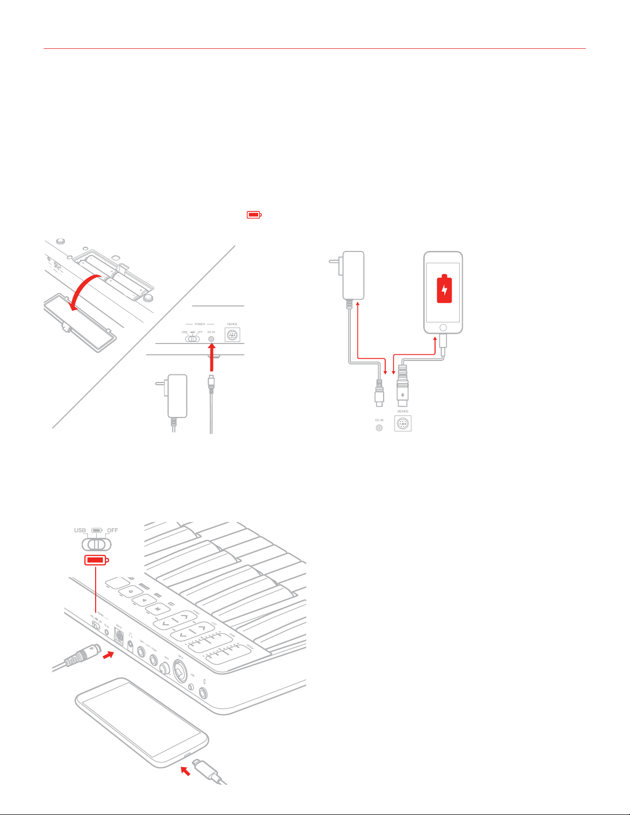
iRig Keys I/O can be USB bus powered, powered by internal AA batteries or external PSU (not included).
iOS: when connected to an iOS Device either esternal PSU or batteries are needed. The external PSU (not
included) will charge the iOS Device’s battery. When both batteries and PSU are connected, all the power will be
supplied by the PSU.
USB: typically, when connected to an USB host (MAC, Windows or Android), all the needed power is provided by
the host. If the connected host is not capable to provide the required power either batteries or PSU may be needed.
IMPORTANT: if the power switch is set to and batteries are present, the keyboard will be powered by the
batteries even when connected to a USB host that can provide enough power.
4 x AA
1.1 iOS Devices
1. Connect the Mini-DIN to Lightning cable to the iRig Keys I/O port and to the iOS device port.
2. Move the back side switch to the battery position (both if you are using batteries or the external PSU).
1
2
5
Page 6
English
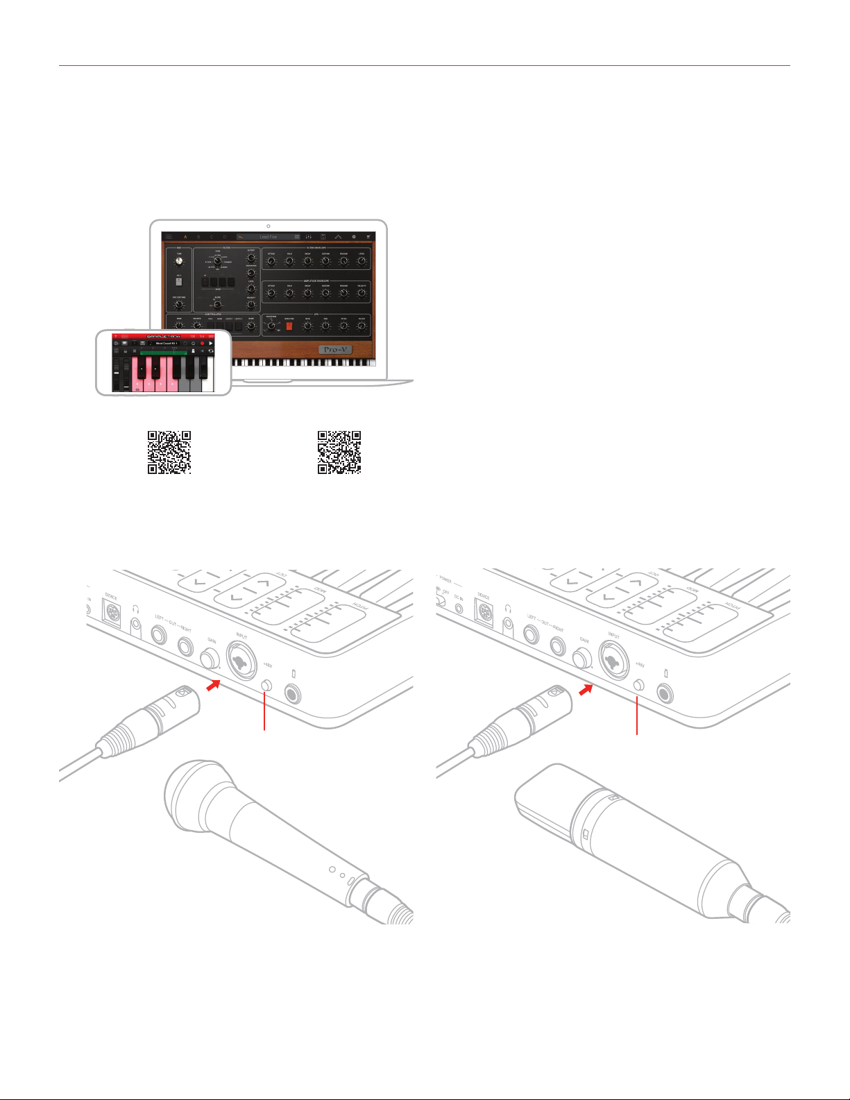
3. Download and launch your favourite APP
SampleTank 3, Miroslav Philharmonik 2 CE*,
Syntronik Pro-V for iOS/Mac/PC, and T-RackS Deluxe,
Ableton® Live 9 Lite, PreSonus® Studio One Prime for Mac/
FREE DOWNLOAD
PC
ikdownloads.com/irigkeysio25 ikdownloads.com/irigkeysio49
*iRig Keys I/O 49 only
4. Connect a microphone or an instrument to the input combo jack. If the microphone you are using requires
external phantom power, activate the 48V switch.
XLR
XLR
1
2
48V OFF
48V ON
6
Page 7
English
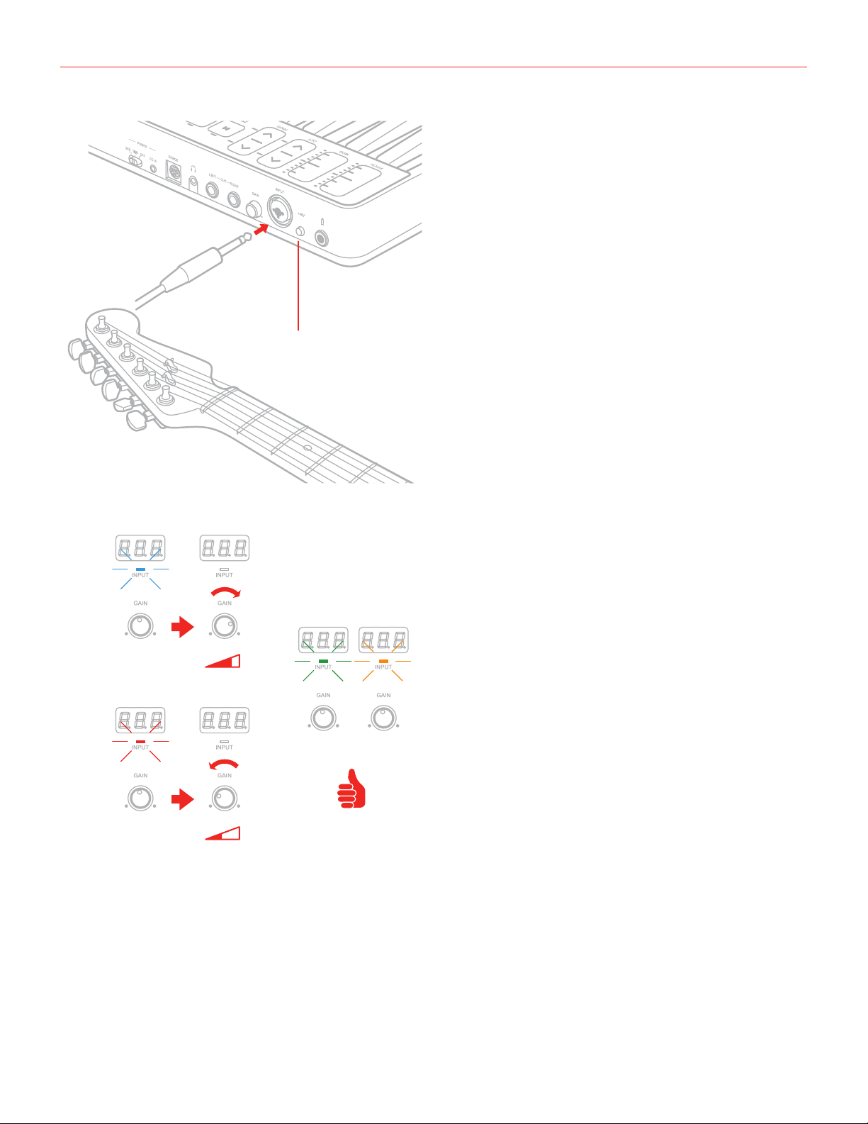
1/4"
48V OFF
5. Adjust the input level with the gain potentiometer.
BLUE
GREEN / ORANGE
RED
7
Page 8
English
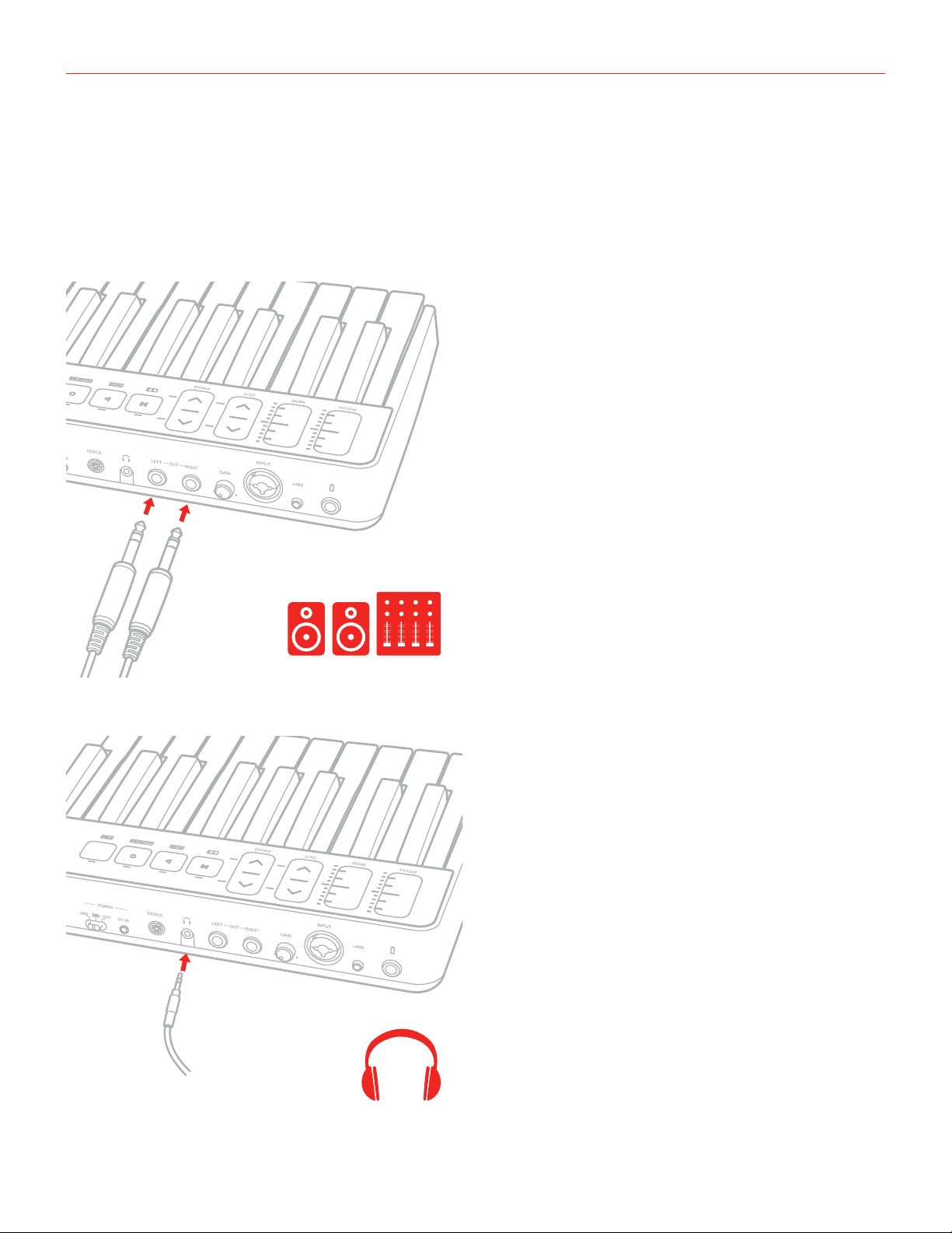
6. Connect a mixer, an amplifier or a PA system to the stereo line outputs. It is possible to control the output
volume with the DATA/VOLUME knob on the top panel (please refer to the instruction on this manual). These
are floating balanced output. This kind of output approximately simulates a floating transformer winding;
if both hot and cold outputs are driving signal lines, then the outputs are balanced, as if a centre- tapped
output transformer were being used. This system has the advantage that it can give the same level into
either a balanced or unbalanced input without rewiring connectors. These kind of outputs are also perfect to
route the onstage signal to a mixer without the need of a DI box, ensuring a loud and pristine signal.
1/4"
7. Connect your headphones to the headphone output. It is possible to control the output volume with the
DATA/VOLUME knob on the top panel (please refer to the instruction on this manual).
8
Page 9
English
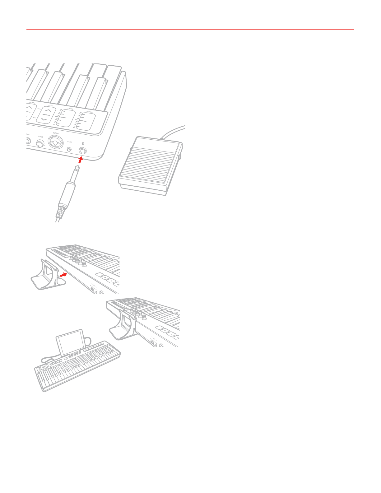
8. If needed, connect a footswitch/expression pedal to the TRS connector on iRig Keys I/O.
9. Fix the tablet holder for a perfect view.
9
Page 10
English
1.2 MAC/PC
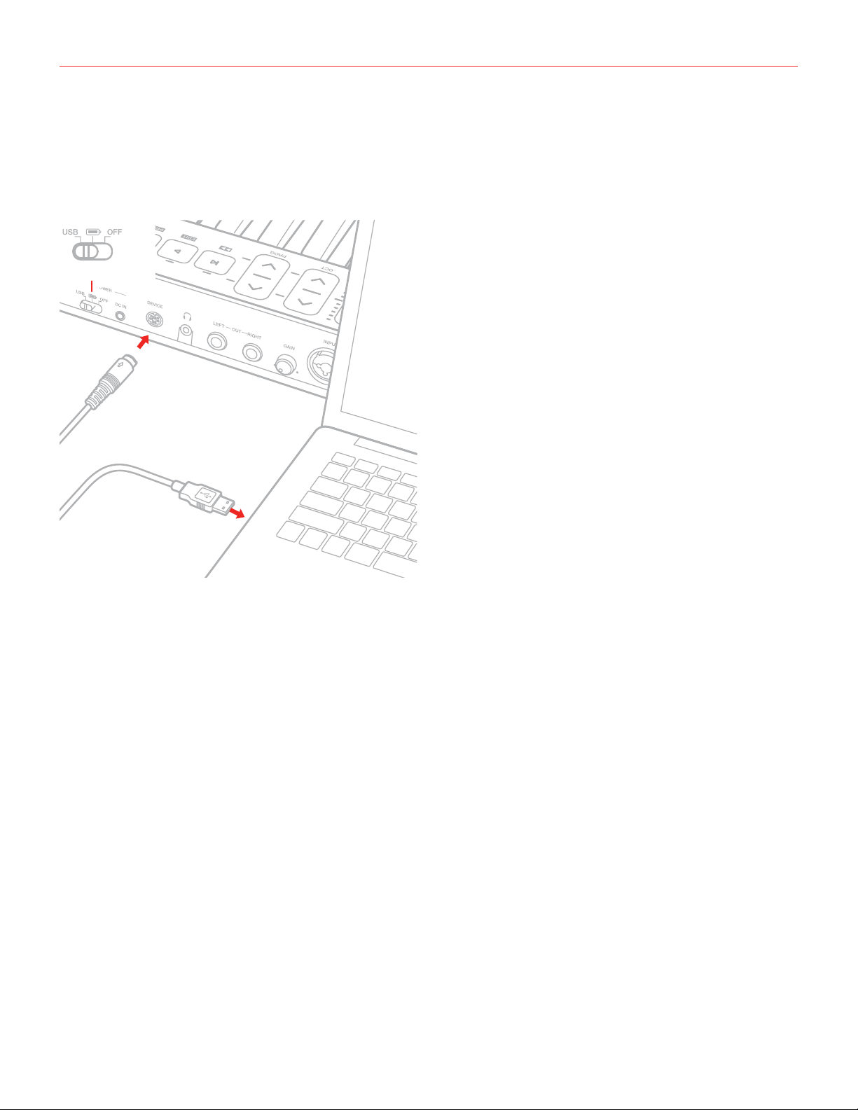
1. Connect the Mini-DIN to USB cable to the iRig Keys I/O port and to a free USB port on your MAC/PC (the
required power is supplied by the USB host).
2. Move the back side switch to the USB position.
USB
1
2
3. Download and launch your favourite Software.
4. Connect a microphone or an instrument to the input combo jack. If the microphone you are using requires
external phantom power, activate the 48V switch. Adjust the input level with the gain potentiometer.
5. Connect a mixer, an amplifier or a PA system to the stereo line outputs. It is possible to control the output
volume with the DATA/VOLUME knob on the top panel (please refer to the instruction on this manual).
6. Connect your headphones to the headphone output. It is possible to control the output volume with the
DATA/VOLUME knob on the top panel (please refer to the instruction on this manual).
7. If needed, connect a footswitch/expression pedal to the TRS connector on iRig Keys I/O.
8. Fix the tablet holder for a perfect view.
10
Page 11
English
2 MIDI controller section
2.1 Keyboard
iRig Keys IO 25 by default plays notes between C2 and C4.
iRig Keys IO 49 by default plays notes between C1 and C5.
If you need to play notes lower or higher than this range, you can shift the whole keyboard in octaves using the
OCT up and down buttons.
2.2 Drumpads
iRig Keys I/O 25 has 8 drum pads, in 2x4 disposition.
iRig Keys I/O 49 has 8 drum pads, in 1x8 disposition.
All the 8 pads on iRig Keys I/O can send MIDI Note ON and OFF, MIDI CH and MIDI CC messages.
On each pad it’s possible to program what kind of message will be sent (Note, CC or MIDI CH).
Each pad is illuminated by a RGB LED and the illumination gives you feedback on the pad status.
2.3 Touch sensitive controls
2.3.1 iRig Keys I/O 49
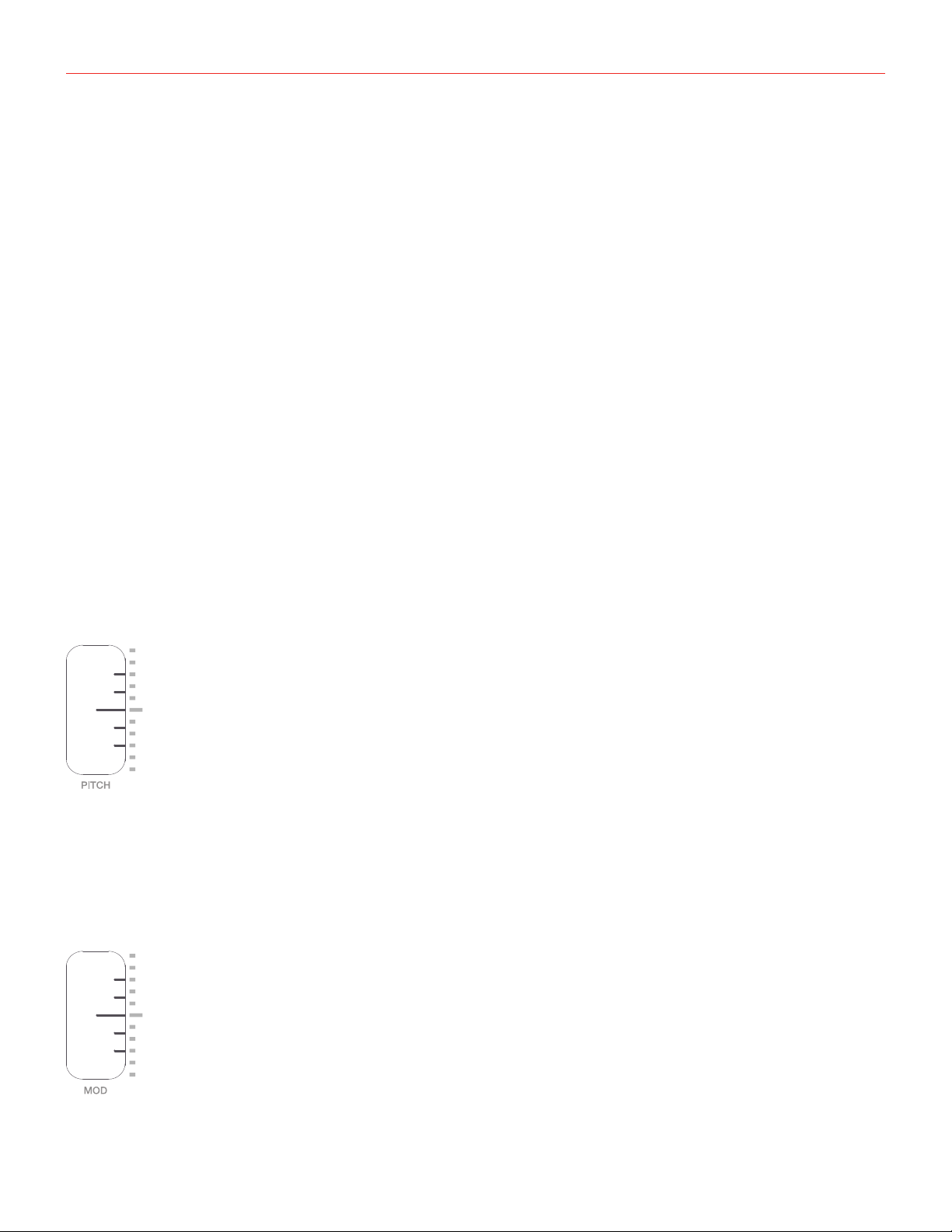
PITCH BEND
Slide this touch sensitive sensor up or down to send Pitch Bend messages. When you don’t touch the sensor,
it return to a central rest position. Moving the finger up will increase the pitch; moving it down will decrease the
pitch.
Note that the amount of pitch change depends on how the receiving virtual instrument is set. This control can be
edited to send any other CC message (see dedicated chapter on this manual).
MODULATION WHEEL
Slide this touch sensitive sensor to send Modulation Wheel messages (MIDI CC#01). The lowest position
11
Page 12
English
sends a value of 0; the highest position sends a value of 127. Most instruments use this message to control the
amount of vibrato or tremolo in the sound, but note that this depends solely on how the receiving instrument
itself is programmed and not on the iRig Keys I/O settings. This control can be edited to send any other CC
message (see dedicated chapter on this chapter).
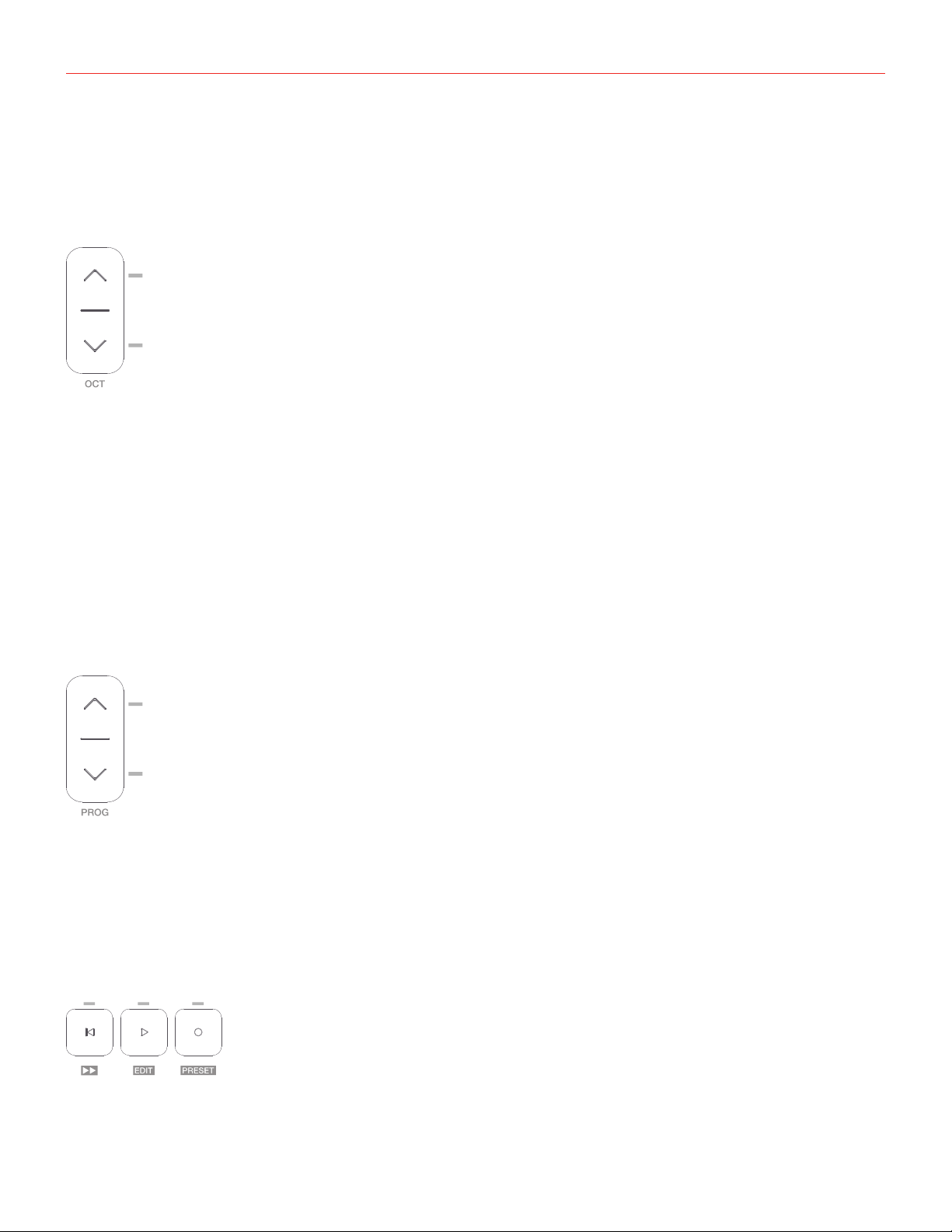
OCTAVE SHIFT
iRig Keys I/O 49 by default plays notes between C1 and C5.
If you need to play notes lower or higher than this range, you can shift the whole keyboard in octaves using the
OCT up and down buttons.
You can shift a maximum of 4 octaves up or 4 octaves down. The OCT buttons LEDs will flash each time you
press them. The number of times they flash corresponds to the number of octaves up or down the keyboard is
shifted.
The displays will inform you about the octave shift indicating a number relative to the octaves that has been
shifted. For example going from 0 to +1 the display will show “ 1” and will remain visible until another action on
the keyboard is performed. Negative shifts will be shown as “ -1”.
PROGRAM CHANGES
Sound modules like virtual instrument apps or plug-ins can switch sounds when they receive the Program
Change MIDI message. iRig Keys I/O sends Program Changes by pressing the PROG up or down buttons.
Starting with the currently selected program, iRig Keys I/O will send the next higher program numbers when
you press PROG UP and lower program numbers when you press PROG DOWN. The 7-segment displays will
inform you about the number relative to the PC number that has been selected. To set the current program see
the dedicated chapter on this manual.
TRANSPORT BUTTONS and ALT BUTTON
These touch-sensitive buttons serves as transport controls, from left to right: Stop/Return-to-Start/FFW (when
ALT button is active), Play and REC. The far right button, labeled as ALT, serves to enable/disable the alternative
12
Page 13

English
functions of buttons and knobs.
When the ALT button is active thetransport buttons above will turn in (from left to right): Fast forward (FFW),
EDIT, PRESET.
EDIT Mode and PRESET Mode functionality will be described later on this manual.
IMPORTANT: configure the transport in the Preset menu so it communicates properly with your software.
2.3.2 iRig Keys I/O 25
MODULATION WHEEL/ PITCH BEND
As primary function this slider act as a Pitch Bend control. By pressing the ALT button, it will switch to
Modulation Whell control.
The operational mode can be edited from hold-mode to return-to-zero mode (see dedicated chapter on this
manual). This control can be edited to send any other CC message (see dedicated chapter on this chapter).
PROGRAM CHANGES/OCTAVE SHIFT
As primary function this cotrol act as Octave control. By pressing the ALT button, it will switch to PROG change
control.
The operational mode can be edited from hold-mode to return-to-zero mode (see dedicated chapter on this
chapter). This control can be edited to send any other CC message (see dedicated chapter on this chapter).
2.4 Knobs
The DATA knob act as browsing control when used in specific software or can be used to send a generic CC
number programmable by the user. It acts also to control the audio output volume when the ALT function is
active. Refer to the dedicated section on this manual for complete editing instructions.
The Knobs 1 to 8 can be assigned to any Control change number. When the ALT function is active the knobs
from 5 to 8 are activeted. Refer to the dedicated section on this manual for complete editing instructions. These
knobs are also touch sensitive: this means that you’ll be able to see the current value of the CC assigned to
each knob by simply touching it. The touch feature allows you, also, to send a specific CC# (momentary and
freely assignable, as described later in this manual) when the knob is touched: it is also possible to disable these
functions as described later in this manual.
The knobs can have different behaviour (Relative or Absolute):
When working in Absolute (ABS) mode the knob will send values from 0 to 127 on the selected CC (+1
increments per clockwise encoder steps and -1 decrements per counter-clockwise encoder steps).
Once values 0 or 127 are reached they will be continued to be sent if the knob is rotated in the same direction.
The starting value from which to send +1 or -1 values will always be the last one sent by the knob the last time it
was moved.
When working in Relative (REL) mode the knob will send custom values to the selected CC. This will allow the
host application to browse long lists of elements easily.
13
Page 14

English
3 Presets
iRig Keys I/O comes with 4 factory presets (F01...F04) and 99 user presets (U01...U99) freely assignable. The
keyaboard can be configurated per personal use: it is possible to configure knobs, pads, touch sliders and
external pedal and all these configurations can be stored, recalled (via RCL or fast-recall) as user presets; the
factory presets can be only recalled.
To enter to the Presets menu, press the ALT button and then the PRESET button:
The display will shows RCL (recall preset) and all the drum pads corresponding to non empty user presets from
U01 to U08 will light on (this will allows you for a rapid recall of the preset).
As said, the display will shows RCL and by rotating the DATA knob it will cycle between STR (store user preset)
and DEL (delete user presets). The press on the DATA knob will select the action.
3.1 Preset recall
• Enter Preset Mode by pressing the ALT and PRESET buttons;
• If a user preset has been previously stored in the first 8 positions, the corresponding pad will light on. This
allows you for a rapid user preset recall (refer to point 1.2 of this manual). If you’d prefer to recall a preset in
the standard way, proceed with the following steps;
• The display will show RCL (recall). Press the DATA push-knob to confirm you want to recall a preset;
• The display will show F01 (factory preset 1). By rotating the DATA knob it will cycle between the factory
presets (F01 to F04) and, eventually, stored user presets.
• Reached the desired preset push the DATA push-knob to confirm the action.
• The keyboard will exit automatically the Preset Mode. You can exit the preset mode any time by pressing the
CANCEL/NO key.
3.2 Rapid user preset recall
The fast-recall feature allows you to recall a user preset directly with the 8 drum-pads: this is usefull in live setup
or where an immediate preset recall is needed.
You can perform a rapid user preset with the drum pads.
• Enter Preset Mode by pressing the ALT and PRESET buttons;
• All the 8 drum pads corresponding to non empty user presets from U01 to U08 will light on;
• Press the drum pad corresponding to the user preset previously stored;
• The keyboard will exit automatically the Preset Mode. You can exit the preset mode any time by pressing the
CANCEL/NO key.
14
Page 15

English
3.3 Preset store
• Enter Preset Mode by pressing the ALT and PRESET buttons;
• The display will show RCL. By rotating the DATA knob it will cycle between STR (store preset) and DEL
(delete presets). Reached the STR position press the DATA push-knob to confirm you want to store a preset;
• The display will show U01 (User preset 1). By rotating the DATA knob it will cycle between the user presets
(U01 to U99);
• Reached the position you want to store the preset on, press the DATA push-knob;
• If the location is empty, the preset will be directly stored on that position and the keyboard will exit
automatically the Preset Mode.
• If the location had a previously stored preset a further confirmation step will be needed to confirm to
overwrite the previous preset. At the press of the DATA push-knob the display will show CFM (confirm) to
confirm that you want to overwrite the previous preset. To confirm this action press the DATA knob, the
preset will be stored and the keyboard will exit automatically the Preset Mode.
• You can exit the preset mode any time by pressing the CANCEL/NO key.
3.4 User presets delete
• Enter Preset Mode by pressing the ALT and PRESET buttons;
• The display will show RCL. By rotating the DATA knob it will cycle between STR (store preset) and DEL
(delete presets). Reached the DEL postition press the DATA push-knob;
• The keyboard will request you to confirm if you want to delete all the user presets previously stored, by
showing CFM;
• By pressing the DATA push-knob all the previously store user presets will be deleted and the keyboard will
exit automatically the Preset Mode;
• You can exit the preset mode any time by pressing the CANCEL/NO key.
15
Page 16

English
4 Factory default settings
4.1 Global settings
Audio Volume : 50
Program Change: 0
Keyboard MIDI CH: 1
Keyboard Velocity: 2 (Normal)
Keyboard Transpose: C
Knobs Touch : ON (Sensing) - OFF (Control Change)
4.2 Factory 1 - IK Virtual Instruments
Generic DAW remote with Absolute knobs
DATA knob -> CC#22 Relative mode (ALT -> audio output volume)
DATA push -> CC#23
Slider 1 -> Pitch Bend / iRig Keys I/O 25 Slider 1-> Pitch Bend (ALT -> Mod Wheel)
Slider 2 -> Mod Wheel / iRig Keys I/O 25 Slider 2-> Octave (ALT -> Prog Change)
Exp Pedal -> Expression CC#11
Sus Pedal -> Sustain CC#64 Momentary action
Pad 1 -> C1
Pad 2-> D1
Pad 3 -> E1
Pad 4 -> F#1
Pad 5 -> A#1
Pad 6 -> G1
Pad 7 -> B1
Pad 8 -> C#2
Pad MIDI CH -> Key
Pad Velocity -> 2 (Normal)
Knob 1 -> CC#12 Absolute mode (Touch CC#30 - OFF by default)
Knob 2 -> CC#13 Absolute mode (Touch CC#31 - OFF by default)
Knob 3 -> CC#14 Absolute mode (Touch CC#32 - OFF by default)
Knob 4 -> CC#15 Absolute mode (Touch CC#33 - OFF by default)
Knob 5 -> CC#16 Absolute mode (Touch CC#34 - OFF by default)
Knob 6 -> CC#17 Absolute mode (Touch CC#35 - OFF by default)
Knob 7 -> CC#18 Absolute mode (Touch CC#36 - OFF by default)
Knob 8 -> CC#19 Absolute mode (Touch CC#37 - OFF by default)
Transport -> MMC
16
Page 17

English
4.2.1 iRig Keys I/O integration with IK Virtual Instruments
SampleTank 3 and Miroslav Philharmonik 2
1. Launch SampleTank 3;
2. Rotate the DATA knob and scroll between the folders of the SampleTank 3 library;
3. Press the DATA knob to disclose a folder and load an instrument;
4. Press PROG up and down buttons to browse and load SampleTank 3 Multis according to the current Live
Set preset loaded on SampleTank 3;
5. Rotate knobs 1 to 4 on iRig Keys I/O to control the first four macros of SampleTank 3. If the Touch CC is
enabled, as soon as you touch a knob this will highlight on the user interface;
6. To access knobs 5 to 8 on your iRig Keys I/O, press the ALT button on the left side of the display, then
rotate, so you can control the remaining next four macros of SampleTnak 3;
17
Page 18

English
Syntronik
1. Launch Syntronik;
2. Rotate the DATA knob and scroll between the presets of Syntronik;
3. Press the DATA knob to load the selected preset;
4. iRig Keys I/O knobs can be easily assigned to any parameter of Syntronik with the MIDI learn function.
18
Page 19

English
4.3 Factory 2 - Apple Logic Pro X/GarageBand
Generic DAW remote with Relative knobs
DATA knob -> CC#22 Relative mode (ALT -> audio output volume)
DATA push -> CC#23
Slider 1 -> Pitch Bend / iRig Keys I/O 25 Slider 1-> Pitch Bend (ALT -> Mod Wheel)
Slider 2 -> Mod Wheel / iRig Keys I/O 25 Slider 2-> Octave (ALT -> Prog Change)
Exp Pedal -> Expression CC#11
Sus Pedal -> Sustain CC#64 Momentary action
Pad 1 -> C1
Pad 2-> D1
Pad 3 -> E1
Pad 4 -> F#1
Pad 5 -> A#1
Pad 6 -> G1
Pad 7 -> B1
Pad 8 -> C#2
Pad MIDI CH -> Key
Pad Velocity -> 2 (Normal)
Knob 1 -> CC#12 Relative mode (Touch CC#30 - OFF by default)
Knob 2 -> CC#13 Relative mode (Touch CC#31 - OFF by default)
Knob 3 -> CC#14 Relative mode (Touch CC#32 - OFF by default)
Knob 4 -> CC#15 Relative mode (Touch CC#33 - OFF by default)
Knob 5 -> CC#16 Relative mode (Touch CC#34 - OFF by default)
Knob 6 -> CC#17 Relative mode (Touch CC#35 - OFF by default)
Knob 7 -> CC#18 Relative mode (Touch CC#36 - OFF by default)
Knob 8 -> CC#19 Relative mode (Touch CC#37 - OFF by default)
Transport -> CC
19
Page 20

English
4.4 Factory 3 - Chromatic PADS + MIDI Volume and MIDI Pan
DATA knob -> CC#22 REL (ALT -> audio output volume)
DATA push -> CC#23
Slider 1 -> Pitch Bend / iRig Keys I/O 25 Slider 1-> Pitch Bend (ALT -> Mod Wheel)
Slider 2 -> Mod Wheel / iRig Keys I/O 25 Slider 2-> Octave (ALT -> Prog Change)
Exp Pedal -> Expression CC#11
Sus Pedal -> Sustain CC#64 Momentary action
Pad 1 -> C3
Pad 2-> C#3
Pad 3 -> D3
Pad 4 -> D#3
Pad 5 -> E3
Pad 6 -> F3
Pad 7 -> F#3
Pad 8 -> G3
Pad MIDI CH -> Key
Pad Velocity -> 2 (Normal)
Knob 1 -> CC#07 Absolute mode (Touch CC#30 - OFF by default)
Knob 2 -> CC#10 Absolute mode (Touch CC#31 - OFF by default)
Knob 3 -> CC#11 Absolute mode (Touch CC#32 - OFF by default)
Knob 4 -> CC#12 Absolute mode (Touch CC#33 - OFF by default)
Knob 5 -> CC#13 Absolute mode (Touch CC#34 - OFF by default)
Knob 6 -> CC#14 Absolute mode (Touch CC#35 - OFF by default)
Knob 7 -> CC#15 Absolute mode (Touch CC#36 - OFF by default)
Knob 8 -> CC#16 Absolute mode (Touch CC#37 - OFF by default)
Transport -> MMC
20
Page 21

English
4.5 Factory 4 - Program Change PADS + MIDI Volume and MIDI Pan
DATA knob -> CC#22 Relative mode (ALT -> audio output volume)
DATA push -> CC#23
Slider 1 -> Pitch Bend / iRig Keys I/O 25 Slider 1-> Pitch Bend (ALT/ Mod Wheel)
Slider 2 -> Mod Wheel / iRig Keys I/O 25 Slider 2-> Octave (ALT/ Prog Change)
Exp Pedal -> Expression CC#11
Sus Pedal -> Sustain CC#64 MOM
Pad 1 -> PC000
Pad 2 -> PC001
Pad 3 -> PC002
Pad 4 -> PC003
Pad 5 -> PC004
Pad 6 -> PC005
Pad 7 -> PC006
Pad 8 -> PC007
Pad MIDI CH -> Key
Pad Velocity -> 6 (Fixed 127)
Knob 1 -> CC#07 Absolute mode (Touch CC#30 - OFF by default)
Knob 2 -> CC#10 Absolute mode (Touch CC#31 - OFF by default)
Knob 3 -> CC#11 Absolute mode (Touch CC#32 - OFF by default)
Knob 4 -> CC#12 Absolute mode (Touch CC#33 - OFF by default)
Knob 5 -> CC#13 Absolute mode (Touch CC#34 - OFF by default)
Knob 6 -> CC#14 Absolute mode (Touch CC#35 - OFF by default)
Knob 7 -> CC#15 Absolute mode (Touch CC#36 - OFF by default)
Knob 8 -> CC#16 Absolute mode (Touch CC#37 - OFF by default)
Transport -> MMC
21
Page 22

English
5 Edit Mode
In Edit Mode you can edit parameters related to the keyboard, pads, touch controls, knobs and perform a
factory reset.
To enter to the Edit Mode, press the ALT button and then the EDIT button:
The display will shows GLO (global menu) to edit the global parameters and, by rotating the DATA knob, PRE
(preset menu) to edit the parameters associated to the preset. It is possible to select global or preset by rotating
the DATA knob: the confirmation of each action is provided by pushing the DATA knob.
In GLO (global menu) you will find: PC (program change) - KEY (keyboard) - TCH (touch knobs) - OFF (all-notesoff) - RST (factory reset)
In PRE (preset menu) you will find: DTA (DATA knob) - ENC (knobs) - PED (external pedal) - PAD (drum pads) SLD (sliders) - TRN (transport).
5.1 Audio output volume
By default the audio output volume is set as ALT function of the DATA knob, so to adjust the audio output
volume press the ALT button and rotate the DATA knob. The audio volume can be assigned as primary or ALT
function by the user. Please refer to the dedicated section on this manual.
5.2 Global edit menu
22
Page 23

English
5.2.1 Send specific MIDI Program Changes numbers, and set Current Program number
iRig Keys I/O can send MIDI Program Changes in two ways:
1. Program Changes are sent sequentially by using the PROG up and PROG down buttons.
2. Program Changes are sent directly by sending a specific Program Change number from within EDIT mode.
After sending a specific Program Change number, the PROG up and down buttons will work sequentially
from that point.
To send a specific Program Change number:
• Enter Edit Mode by pressing the ALT and EDIT buttons;
• The display will show GLO. Press the DATA push-knob to confirm you want to edit a parameter in the global
menu;
• By rotating the DATA knob it will cycle between the parameters of the Global menu;
• Reached the PC (programm change) position pess the DATA push-knob to confirm you want to set a
Programm change;
• The display will show NBR (number) to let you insert the PC number. Insert the PC number (from 0 to 127)
with the keys marked from 0 to 9. You can cancel your input with the CANCEL/NO key;
• To confirm your input press the DATA push-knob;
• The keyboard will exit automatically the Edit Mode;
• You can exit the Edit mode any time by pressing the CANCEL/NO key.
5.2.2 Keyboard edit
• Enter Edit Mode by pressing the ALT and EDIT buttons;
• The display will show GLO. Press the DATA push-knob to confirm you want to edit a parameter in the global
menu;
• By rotating the DATA knob you will cycle between the parameters of the Global menu;
• Reached the KEY position pess the DATA push-knob to confirm you want to edit the keyaboard parameters;
• The display will shows CH (MIDI channel) and by rotating the DATA knob it will cycle between VEL (velocity)
-> TRS (transpose).
23
Page 24

English
5.2.2.1 Set the MIDI Transmit Channel of the keyboard
MIDI instruments can respond to 16 different MIDI channels. For iRig Keys I/O to play an instrument, you need
the iRig Keys I/O MIDI Transmit Channel to match the receiving channel of your instrument.
To set the MIDI Transmit Channel:
• Enter Edit Mode by pressing the ALT and EDIT buttons;
• The display will show GLO. Press the DATA push-knob to confirm you want to edit a parameter in the global
menu;
• By rotating the DATA knob you will cycle between the parameters of the Global menu
• Reached the KEY position pess the DATA push-knob to confirm you want to edit the keyaboard parameters;
• The display will shows CH (MIDI channel).
• Press the DATA puch-knob to confirm you want to set a MIDI channel;
• The display will show the current MIDI channel number;
• By rotating the DATA knob you can select the MIDI channel numer from 1 to 16;
• To confirm your input press the DATA push-knob;
• The keyboard will exit automatically the Edit Mode;
• You can exit the Edit mode any time by pressing the CANCEL/NO key.
5.2.2.2 Set different velocity (touch) response to the keyboard
The keyboard on iRig Kyes I/O is velocity sensitive. Usually this means that the harder you hit the keys, the
louder the sound that is produced. However this ultimately depends on how the instrument you’re controlling is
programmed and your playing style.
In order to match the style of individual users, iRig Keys I/O offers six different velocity response settings:
1. VEL SENS, LIGHT. Use this setting if you prefer a light touch on the keys. This is especially useful when you
need to play fast passages or program drum patterns.
2. VEL SENS, NORMAL. This setting is the default setting and works well in most cases.
3. VEL SENS, HEAVY. Use this setting if you prefer a heavy touch on the keys.
4. FIXED, 64. This setting will always send a fixed MIDI velocity value of 64 without any touch response.
5. FIXED, 100. This setting will always send a fixed MIDI velocity value of 100 without any touch response.
6. FIXED, 127. This setting will always send a fixed MIDI velocity value of 127 without any touch response.
To set the velocity response:
• Enter Edit Mode by pressing the ALT and EDIT buttons;
24
Page 25

English
• The display will show GLO. Press the DATA push-knob to confirm you want to edit a parameter in the
global menu;
• By rotating the DATA knob you will cycle between the parameters of the Global menu
• Reached the KEY position pess the DATA push-knob to confirm you want to edit the keyaboard
parameters;
• The display will shows CH (MIDI channel) and by rotating the DATA knob it will cycle between VEL (velocity)
-> TRS (transpose);
• Reached the VEL position press the DATA push-knob to confirm you want to set a Velocity response;
• The display will show the current Velocity value. By rotating the DATA knob you can select the velocity
response from 1 to 6;
• To confirm your input press the DATA push-knob;
• The keyboard will exit automatically the Edit Mode;
• You can exit the Edit mode any time by pressing the CANCEL/NO key.
5.2.2.3 Transpose the keyboard in semitones
The iRig Keys I/O keyboard can be transposed in semitones. This can be useful when, for example, you need
to play a song that is in a difficult key, but you still want to physically play it in an easier or more familiar key.
To transpose iRig Keys I/O:
• Enter Edit Mode by pressing the ALT and EDIT buttons;
• The display will show GLO. Press the DATA push-knob to confirm you want to edit a parameter in the
global menu;
• By rotating the DATA knob you will cycle between the parameters of the Global menu;
• Reached the KEY position pess the DATA push-knob to confirm you want to edit the keyboard parameters;
• The display will shows CH (MIDI channel) and by rotating the DATA knob it will cycle between VEL (velocity)
-> TRS (transpose);
• Reached the TRS position press the DATA puch-knob to confirm you want to transpose the keyboard;
• The display will show current transpose value (C by default). Press any note on the first octave on the left of
the keyboard.
• The display will show the selected note (black keys will be rapresented with a dot near the note letter);
• To confirm your input press the DATA push-knob;
• The keyboard will exit automatically the Edit Mode;
• You can exit the Edit mode any time by pressing the CANCEL/NO key.
25
Page 26

English
5.2.3 Enable/disable touch knob features
iRig Keys I/O touch sensitive knobs allows you to see the current value setted on each knob by touch it. Also,
each touch can send a CC freely assignable. It is possible to enable/disable these features:
• Enter Edit Mode by pressing the ALT and EDIT buttons;
• The display will show GLO. Press the DATA push-knob to confirm you want to edit a parameter in the global
menu;
• By rotating the DATA knob you will cycle between the parameters of the Global menu;
• Reached the TCH position pess the DATA push-knob to confirm you want to enable/disable the touch
feature;
• The display will show CC and will cycle between CC and SNS. The CC (control change) allows you to
enable or disable the sending of the CC message associated to the touch of each knob; the SNS (sensing)
allows you to enable or disable the capacite sensitive feature of the knobs. These are the possible
combinations: CC (OFF) and SNS (ON), default -> the CC assigned to the touch of the knob is OFF; CC
(ON) and SNS (OFF) -> the CC assigned to the touch of the knob is sent when you start rotating the knob
and not when the knob is just touched;
• If you select, for example, CC:
• By rotating the DATA knob clockwise you’ll turn ON the feature; turning counter-clockwise the DATA knob
you’ll turn it OFF. By default this feature is set to OFF;
• If you select, for example, SNS:
• By rotating the DATA knob clockwise you’ll turn ON the feature; turning counter-clockwise the DATA knob
you’ll turn it OFF.
• To confirm your input press the DATA push-knob;
• The keyboard will exit automatically the Edit Mode;
• You can exit the Edit mode any time by pressing the CANCEL/NO key.
26
Page 27

English
5.2.4 Send “All Notes Off” MIDI message
Sometimes it may be necessary to stop all notes playing on the current MIDI channel when they are stuck or
when controllers are not resetting properly.
iRig Keys I/O can send MIDI CC# 121 + 123 to reset all controllers and stop all notes. To reset all controllers and
set all notes off:
• Enter Edit Mode by pressing the ALT and EDIT buttons;
• The display will show GLO. Press the DATA push-knob to confirm you want to edit a parameter in the global
menu;
• By rotating the DATA knob you will cycle between the parameters of the Global menu;
• Reached the OFF position pess the DATA push-knob to confirm you want to send a note off message;
• The keyboard will exit automatically the Edit Mode;
• You can exit the Edit mode any time by pressing the CANCEL/NO key.
5.2.5 Reset iRig Keys I/O
iRig Keys I/O can be reset to its original factory value of MIDI channel, Programm change, Audio volume, active
preset, velocity, transpose, octave and controls assignations. Note that the factory reset won’t delete the store
User presets.
To reset iRig Keys I/O:
• Enter Edit Mode by pressing the ALT and EDIT buttons;
• The display will show GLO. Press the DATA push-knob to confirm you want to edit a parameter in the global
menu;
• By rotating the DATA knob you will cycle between the parameters of the Global menu;
• Reached the RST position press the DATA push-knob to confirm you want to reset the keyboard
parameters;
• The keyboard will request you to confirm if you want to perform the reset, by showing CFM;
• By pressing the DATA push-knob the keyaboard will be resetted and it will exit automatically the Preset
Mode;
• You can exit the preset mode any time by pressing the CANCEL/NO key.
27
Page 28

English
5.3 Preset edit menu
5.3.1 DATA Knob
You can assign to the DATA push-knob different behaviour (Relative or Absolute), Control Change messages or
audio volume control.
When working in Absolute (ABS) mode the knob will send values from 0 to 127 on the selected CC (+1
increments per clockwise knob steps and -1 decrements per counter-clockwise knob steps).
Once values 0 or 127 are reached they will be continued to be sent if the knob is rotated in the same direction.
The starting value from which to send +1 or -1 values will always be the last one sent by the knob the last time it
was moved.
When working in Relative (REL) mode the knob will send custom values to the selected CC. This will allow the
host application to browse long lists of elements easily.
5.3.1.1 Edit the DATA knob
• Enter Edit Mode by pressing the ALT and EDIT buttons;
• The display will show GLO. Rotate the DATA knob until you reach the PRE position. Press the DATA push-
knob to confirm you want to edit a parameter in the preset menu;
• The display will show DTA. Press the DATA push-knob to confirm you want to edit the DATA knob
parameters;
• The display will show 1 and will cycle between 1 and 2 by rotating the DATA knob. This allows you to edit
the DATA knob message when the ALT button is active (2) or not active (1);
• Select the mode by press the DATA push knob to confirm the action;
• The display will show VOL and will cycle between VOL and CC by rotating the DATA knob;
• If you want to use the DATA knob (primary or alternative function) to act as the audio output volume select
VOL, otherwise select CC if you want to assign a generic control change message to the DATA knob.
• If VOL is selected the keyboard will exit the EDIT mode.
• If CC is selected the display will show ROT and will cycle between ROT (rotary) and PSH (push);
• Select ROT if you want to assign a generic CC message to the rotation of the knob; Select PSH if you want
to assign a generic CC message to the push of the knob;
28
Page 29

English
• If ROT is selected the display will show ABS and can cycle between ABS (ABSOLUTE) and REL (relative).
Select one of the two modes by pressing the DATA push-knob;
• The display will show NBR (number) to let you insert the CC number. Insert the CC number (from 0 to 127)
with the keys marked from 0 to 9. You can cancel your input with the CANCEL/NO key
• To confirm your input press the DATA push-knob;
• The keyboard will exit automatically the Edit Mode;
• You can exit the Edit mode any time by pressing the CANCEL/NO key.
5.3.2 Knob edit
You can assign a specific CC number to the knobs (1 to 8):
• Enter Edit Mode by pressing the ALT and EDIT buttons;
• The display will show GLO. Rotate the DATA knob until you reach the PRE position. Press the DATA push-
knob to confirm you want to edit a parameter in the preset menu;
• The display will show DTA. Rotate the the DATA knob clockwise to reach the KNB position;
• Reached the KNB position press the DATA push-knob to confirm you want to edit the knob parameters;
• The display will show 1 to indicate that the selected knob is the number 1. By rotating the DATA knob you
can chose which knob to edit from 1 to 8. Knobs 5 to 8 will be active once the ALT button is ON.
• Reached the desired knob number press the DATA push-knob to confirm you want to edit that knob;
• The display will show ROT (rotative) to assign a CC to the rotation of the knob; or TCH (touch) to assign
a CC to the touch of the knob (this will work only if the Touch feature is active in the Global menu: refer to
point 3.1.4 of this manual);
• Select the mode you want to assign by pressing the DATA knob;
• If you have selected ROT the display will show ABS and can cycle between ABS (ABSOLUTE) and REL
(relative). Select one of the two modes by pressing the DATA push-knob;
• The display will show NBR (number) to let you insert the CC number you want to assign to the knob;
• Insert the MIDI control change number (from 0 to 127) with the keys marked from 0 to 9. You can cancel
29
Page 30

English
your input with the CANCEL/NO key;
• To confirm press the DATA push-knob;
• The keyboard will exit automatically the Edit Mode;
• You can exit the Edit mode any time by pressing the CANCEL/NO key.
5.3.3 External pedal edit
iRig Keys I/O has an external pedal input that works with both sustain and expression pedals. The external
pedal can be programmed to send CCs and PCs.
5.3.3.1 Assign CC to the expression pedal
• Enter Edit Mode by pressing the ALT and EDIT buttons;
• The display will show GLO. Rotate the DATA knob until you reach the PRE position. Press the DATA push-
knob to confirm you want to edit a parameter in the preset menu;
• The display will show DTA. Rotate the the DATA knob clockwise to reach the PED position;
• Reached the PED position press the DATA push-knob;
• The display will show EXP (expression). Press the DATA push knob to confirm you want to edit the message
sent by the Expression pedal;
• The display will show NBR (number) to let you insert the CC number you want to assign to the knob;
• Insert the MIDI control change number (from 0 to 127) with the keys marked from 0 to 9. You can cancel
your input with the CANCEL/NO key;
• To confirm press the DATA push-knob;
• The keyboard will exit automatically the Edit Mode;
• You can exit the Edit mode any time by pressing the CANCEL/NO key.
5.3.3.2 Assign CC to the Sustain pedal
30
Page 31

English
• Enter Edit Mode by pressing the ALT and EDIT buttons;
• The display will show GLO. Rotate the DATA knob until you reach the PRE position. Press the DATA push-
knob to confirm you want to edit a parameter in the preset menu;
• The display will show DTA. Rotate the the DATA knob clockwise to reach the PED position;
• Reached the PED position press the DATA push-knob;
• The display will show EXP and will cycle to EXP (expression) to SUS (sustain) turning the DATA knob. Press
the DATA push knob to confirm you want to edit the message sent by the Sustain pedal;
• The display will show CC. Press the DATA push-knob to confirm you want to assign a CC to the Sustain
pedal;
• The display will show NBR (number) to let you insert the CC number you want to assign to the knob;
• Insert the MIDI control change number (from 0 to 127) with the keys marked from 0 to 9. You can cancel
your input with the CANCEL/NO key;
• To confirm press the DATA push-knob;
• The display will show MOM (momentary) or LCH (latch) to let you set the way the pedal will send the
message. To confirm press the DATA push-knob;
• The keyboard will exit automatically the Edit Mode;
• You can exit the Edit mode any time by pressing the CANCEL/NO key.
5.3.3.3 Assign PC to the Sustain pedal
• Enter Edit Mode by pressing the ALT and EDIT buttons;
• The display will show GLO. Rotate the DATA knob until you reach the PRE position. Press the DATA push-
knob to confirm you want to edit a parameter in the preset menu;
• The display will show DTA. Rotate the the DATA knob clockwise to reach the PED position;
• Reached the PED position press the DATA push-knob;
• The display will show EXP and will cycle to EXP (expression) to SUS (sustain) turning the DATA knob. Press
the DATA push knob to confirm you want to edit the message sent by the Sustain pedal;
• The display will show CC and will cycle between CC and PC turning the DATA knob. Reached the PC
position press the DATA push-knob to confirm you want to assign a PC to the Sustain pedal;
• The display will show NBR (number) to let you insert the CC number you want to assign to the knob;
31
Page 32

English
• Insert the MIDI control change number (from 0 to 127) with the keys marked from 0 to 9. You can cancel
your input with the CANCEL/NO key;
• To confirm press the DATA push-knob;
• The keyboard will exit automatically the Edit Mode;
• You can exit the Edit mode any time by pressing the CANCEL/NO key.
5.3.4 Pads edit
To the 8 pads it is possible to assign a MIDI channel (that can be the same of the Keyboard global MIDI channel,
or be differnt one), change velocity, assign notes, CCs and PCs.
5.3.4.1 Set the MIDI Transmit Channel
MIDI instruments can respond to 16 different MIDI channels. For iRig Keys I/O pads to play an instrument, you
need the iRig Keys I/O pads MIDI Transmit Channel to match the receiving channel of your instrument.
To set the MIDI Transmit Channel associated to the pads:
• Enter Edit Mode by pressing the ALT and EDIT buttons;
• The display will show GLO. Rotate the DATA knob until you reach the PRE position. Press the DATA push-
knob to confirm you want to edit a parameter in the preset menu;
• The display will show DTA. Rotate the the DATA knob clockwise to reach the PAD position;
• Reached the PAD position press the DATA push-knob;
• The display will show CH. Press the DATA push-knob to confirm you want to assign a MIDI CH to the 8
pads;
• The display will show the current MIDI channel setted fot the pads;
• Turning the DATA knob you can cycle between channel 1 and 16, plus the current MIDI channel setted for
the rest of the Keyboard, marked as KEY. This way the MIDI channel of the pads will be fixed to the MIDI
channel of the keyboard.
• Reached the position you want, press the DATA push-knob;
• The keyboard will exit automatically the Edit Mode;
• You can exit the Edit mode any time by pressing the CANCEL/NO key.
32
Page 33

English
5.3.4.2 Set different velocity (touch) response
The pads on iRig Keys I/O are velocity sensitive. Usually this means that the harder you hit the pads, the louder
the sound that is produced. However this ultimately depends on how the instrument you’re controlling is
programmed and your playing style.
In order to match the style of individual users, iRig Keys I/O offers six different velocity response settings:
1. VEL SENS, LIGHT. Use this setting if you prefer a light touch on the keys. This is especially useful when you
need to play fast passages or program drum patterns.
2. VEL SENS, NORMAL. This setting is the default setting and works well in most cases.
3. VEL SENS, HEAVY. Use this setting if you prefer a heavy touch on the keys.
4. FIXED, 64. This setting will always send a fixed MIDI velocity value of 64 without any touch response.
5. FIXED, 100. This setting will always send a fixed MIDI velocity value of 100 without any touch response.
6. FIXED, 127. This setting will always send a fixed MIDI velocity value of 127 without any touch response.
To set the velocity response:
• Enter Edit Mode by pressing the ALT and EDIT buttons;
• The display will show GLO. Rotate the DATA knob until you reach the PRE position. Press the DATA push-
knob to confirm you want to edit a parameter in the preset menu;
• The display will show DTA. Rotate the DATA knob clockwise to reach the PAD position;
• Reached the PAD position press the DATA push-knob;
• The display will show CH and will . Rotate the the DATA knob clockwise to reach the VEL position;
• The display will show the current velocity value (1 to 6);
• By rotating the DATA knob you can select the velocity response from 1 to 6;
• To confirm your input press the DATA push-knob;
• The keyboard will exit automatically the Edit Mode;
• You can exit the Edit mode any time by pressing the CANCEL/NO key.
5.3.4.3 Single Pad editing
You can assign a Note a CC or a PC to any drum pad. To edit the single pad:
• Enter Edit Mode by pressing the ALT and EDIT buttons;
• The display will show GLO. Rotate the DATA knob until you reach the PRE position. Press the DATA push-
knob to confirm you want to edit a parameter in the preset menu;
• The display will show DTA. Rotate the DATA knob clockwise to reach the PAD position;
33
Page 34

English
• Reached the PAD position press the DATA push-knob;
• The display will show CH and will . Rotate the the DATA knob clockwise to reach the PAD position;
• The display will show SEL (select) and the 8 pads will start to pulse slowly;
• To select the desired pad press it: the selected pad will begin to slowly pulse;
• The display will show NTE (note) and by rotating the DATA knob it will cycle to CC (control change) and PC
(program change). Select NTE with the DATA puch-knob if you want to assign a Note to the selected pad,
select CC if you want to assign a control change to the selcted pad, or selct PC if you want to assign a
program change to the selected pad;
To assign a Note, select NTE with the DATA puch-knob as described above:
• The display will show C3 by default;
• You can assign any note pressing any key on the first octave on the left of the keyboard;
• Once you have assigned the note you can choose the octave by rotating the DATA knob. The display will
show you the note and the octave you have chosen;
• To confirm press the DATA push-knob. To cancel press the CANCEL/NO key (this way the note won’t be
assigned and the keyboard will wxit the Edit Mode);
• The keyboard will return to display SEL to let you select another pad to be edited.
• If you want to edit another pad repeat the step above, otherwise press the DATA push-knob to confirm your
editing. If you want to not confirm the editing press the CANCEL/NO key.
• The keyboard will exit automatically the Edit Mode.
To assign a CC, select CC with the DATA push-knob as described above:
• The display will show NBR (number) to let you insert the MIDI control change number. Insert the MIDI
control change number (from 0 to 127) with the keys marked from 0 to 9. You can cancel your input with the
CANCEL/NO key
• To confirm press the DATA push-knob;
• The display will show MOM (momentary) or LCH (latch) to let you set the way the pad will send the
message. To confirm press the DATA push-knob;
• The keyboard will return to display SEL to let you select another pad to be edited;
34
Page 35

English
• If you want to edit another pad repeat the step above, otherwise press the DATA push-knob to confirm your
editing. If you want to not confirm the editing press the CANCEL/NO key.
• The keyboard will exit automatically the Edit Mode.
To assign a PC, select PC with the DATA push-knob as described above:
• The display will show NBR (number) to let you insert the MIDI control change number. Insert the MIDI
control change number (from 0 to 127) with the keys marked from 0 to 9. You can cancel your input with the
CANCEL/NO key
• To confirm press the DATA push-knob;
• The keyboard will return to display SEL to let you select another pad to be edited;
• If you want to edit another pad repeat the step above, otherwise press the DATA push-knob to confirm your
editing. If you want to not confirm the editing press the CANCEL/NO key.
• The keyboard will exit automatically the Edit Mode.
5.3.5 Slider edit
It is possible to assign any CC to each sliders.
5.3.5.1 Assign a Pitch bend command to a slider
To assign a pitch bend command to a slider:
• Enter Edit Mode by pressing the ALT and EDIT buttons;
• The display will show GLO. Rotate the DATA knob until you reach the PRE position. Press the DATA push-
knob to confirm you want to edit a parameter in the preset menu;
• The display will show DTA. Rotate the DATA knob clockwise to reach the SLD position;
• Reached the SLD position press the DATA push-knob;
• The display will show SEL (select) to let you select the control you want to edit. All the led bars will start to
pulse;
35
Page 36

English
• Press or touch the slider you want to edit;
• The display will show PCH (pitch) and by rotating the DATA knob it will cycle to MOD (MOD wheel) -> CC
(control change).
• Reached the PCH position press the DATA push-knob to confirm you want to assign a pitch bend command
to the slider;
• The keyboard will exit automatically the Edit Mode;
• You can exit the Edit mode any time by pressing the CANCEL/NO key.
5.3.5.2 Assign a Mod wheel command to a slider
To assign a Mod wheel command to a slider:
• Enter Edit Mode by pressing the ALT and EDIT buttons;
• The display will show GLO. Rotate the DATA knob until you reach the PRE position. Press the DATA push-
knob to confirm you want to edit a parameter in the preset menu;
• The display will show DTA. Rotate the DATA knob clockwise to reach the SLD position;
• Reached the SLD position press the DATA push-knob;
• The display will show SEL (select) to let you select the control you want to edit. All the led bars will start to
pulse;
• Press or touch the slider you want to edit;
• The display will show PCH (pitch) and by rotating the DATA knob it will cycle to MOD (MOD wheel) -> CC
(control change).
• Reached the MOD position press the DATA push-knob to confirm you want to assign a modulation wheel
command to the slider;
• The keyboard will exit automatically the Edit Mode;
• You can exit the Edit mode any time by pressing the CANCEL/NO key.
36
Page 37

English
5.3.5.3 Assign a CC message to a slider
You can assign the fader mode (hold or return to zero) as well as the CC number associated to the slider.
Hold mode: the slider will act like a mechanical fader, so it will retain the position;
Return to zero mode: in this mode the slider will automatically return to zero position once not touched;
To assign a generic CC message to a slider:
• Enter Edit Mode by pressing the ALT and EDIT buttons;
• The display will show GLO. Rotate the DATA knob until you reach the PRE position. Press the DATA push-
knob to confirm you want to edit a parameter in the preset menu;
• The display will show DTA. Rotate the DATA knob clockwise to reach the SLD position;
• Reached the SLD position press the DATA push-knob;
• The display will show SEL (select) to let you select the control you want to edit. All the led bars will start to
pulse;
• Press or touch the slider you want to edit;
• The display will show PCH (pitch) and by rotating the DATA knob it will cycle to MOD (MOD wheel) -> CC
(control change).
• Reached the CC position press the DATA push-knob to confirm you want to assign a CC message to the
slider;
• The display will show HLD (hold mode) and by rotating the DATA knob it will cycle to RET (return to zero
mode);
• Select the mode you need by pressing the DATA push-knob;
• The display will show NBR (number) to let you insert the CC number you want to assign to the slider;
• Insert the MIDI control change number (from 0 to 127) with the keys marked from 0 to 9. You can cancel
your input with the CANCEL/NO key;
• To confirm press the DATA push-knob;
• The keyboard will exit automatically the Edit Mode;
• You can exit the Edit mode any time by pressing the CANCEL/NO key.
37
Page 38

English
5.3.6 Slider editing on iRig Keys I/O 25
iRig Keys I/O 25 has two sliders that send by default picth/mod message and Octave/PC message. It is possible
to edit both the sliders to send different messages.
5.3.6.1 Assign a Pitch bend command to a slider
To assign a pitch bend command to a slider:
• Enter Edit Mode by pressing the ALT and EDIT buttons;
• The display will show GLO. Rotate the DATA knob until you reach the PRE position. Press the DATA push-
knob to confirm you want to edit a parameter in the preset menu;
• The display will show DTA. Rotate the DATA knob clockwise to reach the SLD position;
• Reached the SLD position press the DATA push-knob;
• The display will show SEL (select) to let you select the control you want to edit. All the led bars will start to
pulse;
• Press or touch the slider you want to edit;
• The display will show 1 and will cycle between 1 and 2. This means that you can assign the desired control
to the primary (1) or alternative (2) function of the slider;
• The display will show PCH (pitch) and by rotating the DATA knob it will cycle to MOD (MOD wheel) -> CC
(control change) -> OCT (octave) -> PC (Programm Change).
• Reached the PCH position press the DATA push-knob to confirm you want to assign a pitch bend command
to the slider;
• The keyboard will exit automatically the Edit Mode;
• You can exit the Edit mode any time by pressing the CANCEL/NO key.
38
Page 39

English
5.3.6.2 Assign a Mod wheel command to a slider
To assign a Mod wheel command to a slider:
• Enter Edit Mode by pressing the ALT and EDIT buttons;
• The display will show GLO. Rotate the DATA knob until you reach the PRE position. Press the DATA push-
knob to confirm you want to edit a parameter in the preset menu;
• The display will show DTA. Rotate the DATA knob clockwise to reach the SLD position;
• Reached the SLD position press the DATA push-knob;
• The display will show SEL (select) to let you select the control you want to edit. All the led bars will start to
pulse;
• Press or touch the slider you want to edit;
• The display will show 1 and will cycle between 1 and 2. This means that you can assign the desired control
to the primary (1) or alternative (2) function of the slider;
• The display will show PCH (pitch) and by rotating the DATA knob it will cycle to MOD (MOD wheel) -> CC
(control change) -> OCT (octave) -> PC (Programm Change).
• Reached the MOD position press the DATA push-knob to confirm you want to assign a modulation wheel
command to the slider;
• The keyboard will exit automatically the Edit Mode;
• You can exit the Edit mode any time by pressing the CANCEL/NO key.
5.3.6.3 Assign a CC message to a slider
You can assign the fader mode (hold or return to zero) as well as the CC number associated to the slider.
Hold mode: the slider will act like a mechanical fader, so it will retain the position;
Return to zero mode: in this mode the slider will automatically return to zero position once not touched;
To assign a generic CC message to a slider:
• Enter Edit Mode by pressing the ALT and EDIT buttons;
• The display will show GLO. Rotate the DATA knob until you reach the PRE position. Press the DATA push-
knob to confirm you want to edit a parameter in the preset menu;
39
Page 40

English
• The display will show DTA. Rotate the DATA knob clockwise to reach the SLD position;
• Reached the SLD position press the DATA push-knob;
• The display will show SEL (select) to let you select the control you want to edit. All the led bars will start to
pulse;
• Press or touch the slider you want to edit;
• The display will show 1 and will cycle between 1 and 2. This means that you can assign the desired control
to the primary (1) or alternative (2) function of the slider;
• The display will show PCH (pitch) and by rotating the DATA knob it will cycle to MOD (MOD wheel) -> CC
(control change) -> OCT (octave) -> PC (Programm Change).
• Reached the CC position press the DATA push-knob to confirm you want to assign a CC message to the
slider;
• The display will show HLD (hold mode) and by rotating the DATA knob it will cycle to RET (return to zero
mode);
• Select the mode you need by pressing the DATA push-knob;
• The display will show NBR (number) to let you insert the CC number you want to assign to the slider;
• Insert the MIDI control change number (from 0 to 127) with the keys marked from 0 to 9. You can cancel
your input with the CANCEL/NO key;
• To confirm press the DATA push-knob;
• The keyboard will exit automatically the Edit Mode;
• You can exit the Edit mode any time by pressing the CANCEL/NO key.
5.3.6.4 Assign the Octave control to a slider
To assign the Octave control to a slider:
• Enter Edit Mode by pressing the ALT and EDIT buttons;
• The display will show GLO. Rotate the DATA knob until you reach the PRE position. Press the DATA push-
knob to confirm you want to edit a parameter in the preset menu;
• The display will show DTA. Rotate the DATA knob clockwise to reach the SLD position;
• Reached the SLD position press the DATA push-knob;
• The display will show SEL (select) to let you select the control you want to edit. All the led bars will start to
pulse;
40
Page 41

English
• Press or touch the slider you want to edit;
• The display will show 1 and will cycle between 1 and 2. This means that you can assign the desired control
to the primary (1) or alternative (2) function of the slider;
• The display will show PCH (pitch) and by rotating the DATA knob it will cycle to MOD (MOD wheel) -> CC
(control change) -> OCT (octave) -> PC (Programm Change).
• Reached the OCT position press the DATA push-knob to confirm you want to assign a modulation wheel
command to the slider;
• The keyboard will exit automatically the Edit Mode;
• You can exit the Edit mode any time by pressing the CANCEL/NO key.
5.3.6.5 Assign the Program Change control to a slider
To assign the program change control to a slider:
• Enter Edit Mode by pressing the ALT and EDIT buttons;
• The display will show GLO. Rotate the DATA knob until you reach the PRE position. Press the DATA push-
knob to confirm you want to edit a parameter in the preset menu;
• The display will show DTA. Rotate the DATA knob clockwise to reach the SLD position;
• Reached the SLD position press the DATA push-knob;
• The display will show SEL (select) to let you select the control you want to edit. All the led bars will start to
pulse;
• Press or touch the slider you want to edit;
• The display will show 1 and will cycle between 1 and 2. This means that you can assign the desired control
to the primary (1) or alternative (2) function of the slider;
• The display will show PCH (pitch) and by rotating the DATA knob it will cycle to MOD (MOD wheel) -> CC
(control change) -> OCT (octave) -> PC (Programm Change).
• Reached the PC position press the DATA push-knob to confirm you want to assign a modulation wheel
command to the slider;
• The keyboard will exit automatically the Edit Mode;
• You can exit the Edit mode any time by pressing the CANCEL/NO key.
41
Page 42

English
5.3.7 Transport edit
The transport control buttons are dedicated buttons for sending conventional transport control commands:
Stop/Return-to-start/FFW, Play, Record. You can use the transport format editing (in the Preset menu) to set
these buttons to send RT (Real Time), CC (MIDI CC) and MMC (MIDI Machine Control).
To set the transport format:
• Enter Edit Mode by pressing the ALT and EDIT buttons;
• The display will show GLO. Rotate the DATA knob until you reach the PRE position. Press the DATA push-
knob to confirm you want to edit a parameter in the preset menu;
• The display will show DTA. Rotate the DATA knob clockwise to reach the TRN position;
• Reached the TRN position press the DATA push-knob;
• The display will show the current format of the transport buttons: MMC, CC or RT.
• Select the format by pushing the DATA knob push-knob;
• The keyboard will exit automatically the Edit Mode;
• You can exit the Edit mode any time by pressing the CANCEL/NO key.
6 Low Battery
When the battery level approach to be low, the INPUT LED will fast blink red.
Troubleshooting
Sound is distorted.
You’re probably overloading the input. Check that the input gain on iRig Keys I/O is set properly. If the Audio
Level LED is red when you play your instrument or sing or talk into a mic, decrease the input gain as described
in this guide.
I don’t get any sound.
In order for iRig Keys I/O to turn on, a Core Audio-compatible audio app must first be launched on your iOS
device or Mac.
iOS: be sure you are using an app that works with audio input from the Lightning dock connector.
Mac: be sure you have set “iRig Keys I/O” as the audio or MIDI input device on the audio app you are using.
Phantom power doesn’t turn ON when connected to an iOS device.
Check that you have inserted working AA batteries in iRig Keys I/O’s battery compartment, or that you’ve
connected iRig Keys I/O to the external power supply.
I can’t get any sound from my condenser microphone.
Your microphone may need phantom power. Turn phantom power on by moving the iRig Keys I/O botton to the
ON position.
42
Page 43

English
Specifications
Microphone Input
Microphone Input: balanced female 3-pin, XLR. Pin 2: hot / Pin 3: cold / Pin 1: ground
Microphone Input Level: from 6 mVpp to 1.4 Vpp
Microphone Input Impedance: 3.2 kOhms
Gain Range: 46 dB
Phantom Power: +48V ± 4V
Frequency Response: 20 Hz - 20 kHz +/-1.5dB
Input Noise: -100 dB RMS
Instrument Input
Instrument Input: unbalanced, Hi-Z, TS 1/4” Jack, Tip: signal / Shield: ground
Instrument Input Level: from 30 mVpp to 6.9 Vpp
Instrument Input Impedance: 1 MOhms
Gain Range: 27 dB
Frequency Response: 20 Hz - 20 kHz +/-1.5dB
Input Noise: -100 dB RMS
Line Output
Line Outputs: 2x balanced, TRS 1/4” Jack, Tip: hot / Ring: cold / Shield: ground
Floating Balanced Outputs with automatic level compensation when working in unbalanced mode
Maximum Output Level: +13 dBu into 600 Ohms balanced load
Frequency Response: from 10 Hz to 21 kHz (+/- 0.2dB)
Output Dynamic Range: 102 dB(A)
Output Impedance: 150 Ohms balanced
Stereo Headphone Output
Connector: 1/8” TRS Jack. Tip: right / Ring: left / Shield: ground
Headphone Level Power 100mW into 50 Ohms
Other Input/Output
DC barrel: 1x DC barrel. For power and device charging.
Device Connector: mini-DIN
External Pedal Input: 1/4” TRS Jack
Common
Conversion: 16 or 24-bit A/D - D/A
43
Page 44

English
Sampling Rate: 44.1 kHz, 48 kHz, 88.2 kHz and 96 kHz
Power
•USBbuspoweredwhenusedwithacomputer
•Batterypowered(4xAAincluded)whenusedwithaniOSdevice
•DCpowersupply(notincluded,iRigPSU3Asoldseparately)*
Keyboard
Keys: 25 or 49 (depending on the version) full-size keys with velocity
Pads
8 velocity-sensitive multi color assignable pads
Warranty
Please visit:
www.ikmultimedia.com/warranty
for the complete warranty policy.
Support and more info
www.ikmultimedia.com/support
www.irigkeysio.com
Apple is not responsible for the operation of this device or its compliance with safety and regulatory standards.
44
Page 45

Regulatory
FCC statement
This device complies with Part 15.107 and 15.109 Class B of the FCC Rules CFR47:
October 2010.
Operation is subject to the following two conditions:
1. This device may not cause harmful interference.
2. This device must accept any interference received, including interference that may
cause undesired operation.
Changesormodicationsnotexpresslyapprovedbythepartyresponsiblefor
compliance could void the user’s authority to operate the equipment.
“Made for iPod,” “Made for iPhone,” and “Made for iPad” mean that an electronic accessory has been designed to connect specically to iPod, iPhone, or iPad, respectively, and has been certied by
the developer to meet Apple performance standards. Apple is not responsible for the operation of this device or its compliance with safety and regulatory standards. Please note that the use of this
accessory with iPod, iPhone, or iPad may affect wireless performance.
iRig® Keys I/O, iGrand Piano™ and SampleTank® are trademarks property of IK Multimedia Production Srl. All other product names and images, trademarks and artists names are the property of their
respective owners, which are in no way associated or afliated with IK Multimedia. iPad, iPhone, iPod touch Mac and Mac logo are trademarks of Apple Computer, Inc., registered in the U.S. and other
countries. Lightning is a trademark of Apple Inc. App Store is a service mark of Apple Inc.
2017/11/06
45
 Loading...