

Page 1
TTL
Full
1/2
1/4
1/8
Ready Light
Fuel
Gauge
3
2
1
Test
Off
On
On
w/Lite
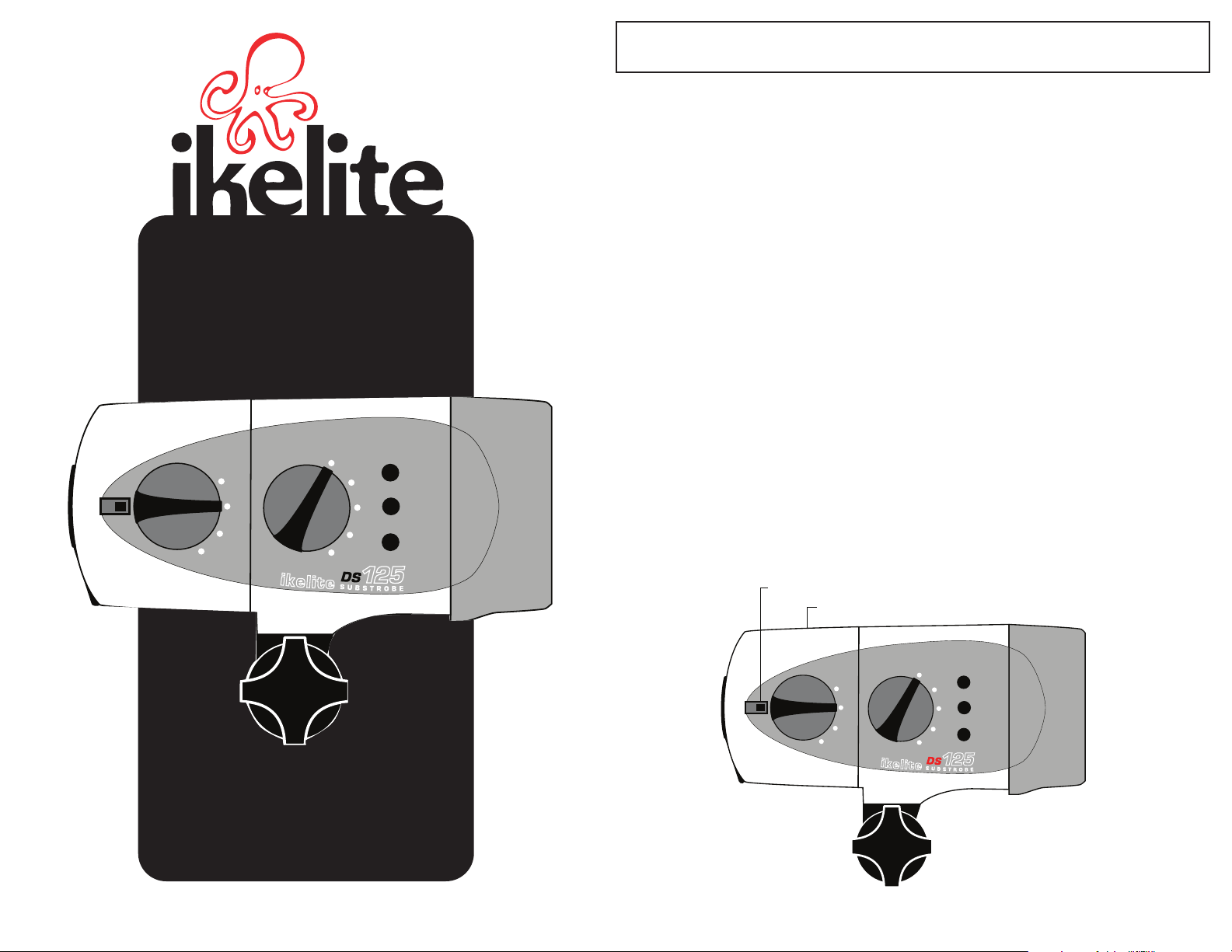
IIKKEELLIITTEE DDSS112255 SSuubbssttrroobbe
TTL
Full
1/2
1/4
1/8
Ready Light
Fuel
Gauge
3
2
1
Test
Off
On
On
w/Lite
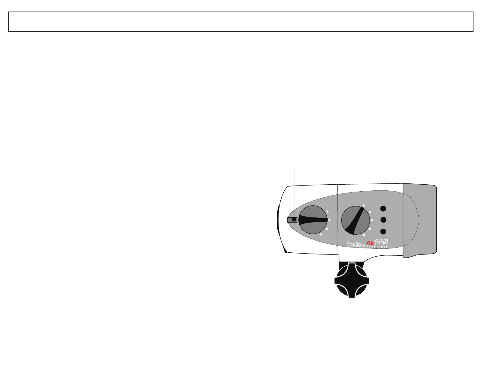
Battery
Compartment
Switch
Lock
e
IIKKEELLIITTEE DDSS112255 SSuubbssttrroobbee ____________________________________________________________________________ ##44006655
SSPPEECCIIFFIICCAATTIIOONNSS
Digital
Substrobe
WWeeiigghhtt::
EEnneerrggyy RRaattiinngg::
CCoovveerraaggee AAnnggllee::
WWiiddeesstt LLeennss::
GGuuiiddee NNuummbbeerr ((IISSOO 110000)) ffeeeett::
GGuuiiddee NNuummbbeerr ((IISSOO 110000)) mmeetteerrss::
FFiirriinngg MMooddeess::
CCoolloorr TTeemmppeerraattuurree::
PPoowweerr SSoouurrccee::
FFllaasshheess::
RReeccyyccllee TTiimmee::
DDeepptthh RRaattiinngg::
......................................................1.2kg (2.7 lbs.) with NiMH
..........................................110 watt-sec.
........................................90°
..............................................Nikonos 20mm or SLR 24mm
................64 surface, 32 underwater
............................................TTL/Auto, Manual, 1/2 M, 1/4 M, 1/8 M
..................................4900°K
............................................7.2-volt, 2.8 amp NiMH pack
......................................................250 full power
............................................1.0 seconds (full power)
............................................90m (300 feet)
100° with diffuser
Nikonos 15mm or SLR 20mm
with diffuser
............20 surface, 10 underwater
Slave featuring auto exposure
using optional DS Sensor #4100.5
Slave featuring 10-manual power settings
using optional EV-Controller #4100.6
DDSS112255
22
Page 2
IIKKEELLIITTEE DDSS112255 SSuubbssttrroobbe
TTL
Full
1/2
1/4
1/8
Ready Light
Fuel
Gauge
3
2
1
Test
Off
On
On
w/Lite
Battery
Compartment
Switch
Lock
e
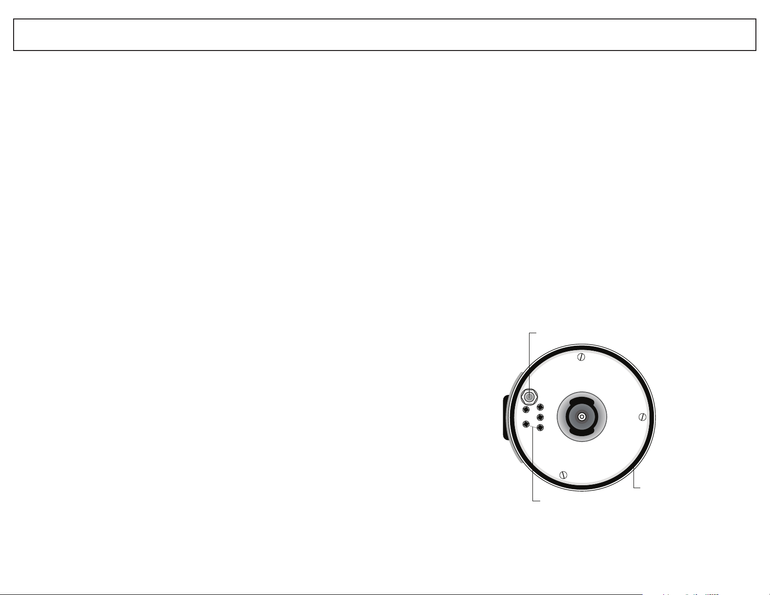
SSWWIITTCCHHEESS // FFUUEELL GGAAUUGGE
E
Thank you for purchasing an Ikelite SUBSTROBE. Ikelite brings 40 years of
underwater photographic and lighting experience to the strobe market. Ikelite
Substrobes are designed and built in the USA by Ikelite to suit both the professional
and the amateur photographer.
DDSS112255 SSUUBBSSTTRROOBBEE ______________________________________________________________________________________________________
The Ikelite DS125 strobe combines high intensity output and wide coverage angle
in a compact, versatile design. This strobe features 110 watt-sec. intensity and covers
a full 100° using the diffuser. Special soft-lite reflector provides rich reds, oranges, and
warmer flesh tones.
The Ikelite DS125 strobe is preflash compatible and operates with both traditional
film cameras and digital still cameras. Multiple firing modes are featured, including
TTL/Auto exposure. Add the optional Ikelite DS Sensor #4100.5 for wireless TTL/Auto
slave capability with select cameras or the Ikelite EV-Controller #4100.6 for 10-manual
power settings.
The DS125 electronics are safely sealed separately from the battery pack. The
industrial grade NiMH batteries recycle in an incredible 1.0 seconds and the NiMH pack
is easily interchangeable with a spare unit. When in the “
TTEESSTT
” position the fuel gauge
references the remaining battery capacity. Aim the DS125 and illuminate your subject's
colors with the built-in modeling light / night diving light.
OOVVEERRVVIIEEWW OOFF DDSS112255 FFEEAATTUURREESS ____________________________________________________________________________
• Separate power and firing mode switches.
• Interchangeable battery pack features industrial grade NiMH batteries.
• LED fuel gauge approximates the remaining battery capacity.
• Visual ready light indicates when strobe has recycled.
• Female Ikelite bulkhead connector accepts different camera sync cords, the Ikelite
DS Sensor #4100.5 or EV-Controller #4100.6.
• Exposure guide label references recommended exposure settings.
• Separate diffuser provides softer lighting and wider coverage angle.
• Strobe mount accommodates most Ikelite arm systems.
BBEECCOOMMIINNGG FFAAMMIILLIIAARR ______________________________________________________________________________________________
Before using the Ikelite Substrobe, please read this owners manual thoroughly and
retain for future reference. We recommend that you become familiar with the features
and functions of the Ikelite Substrobe before trying the camera and strobe in the water.
And if you have not done so, we suggest reading your camera owner's manual.
The DS125 features separate switches for power on/off and firing modes. The arrow
on the switch points to the selected position.
OONN//OOFFFF SSWWIITTCCHH ________________________________________________________________________________________________________
OOFFFF::
The horizontal switch position is OFF. The adjacent tab locks the switch in the
OFF position. To unlock, slide the tab away from the switch. Always turn the Substrobe
OFF before opening the strobe.
OONN::
There are two ON positions. Rotating the switch clockwise to the first ON
position turns on the power to the Substrobe. Further rotation of the switch clockwise to
the second ON position turns on both the power to the Substrobe and the modeling light.
TTEESSTT::
Occasionally check the battery capacity by rotating the switch counterclockwise to the TEST battery position and referencing the fuel gauge on the side of the
strobe. The TEST battery position also turns ON the modeling light as a reminder that
the switch is in the TEST position.
33
44
Page 3
OPEN
RCD
I
N
D
PL
S
I
N
U
.
S
.
A.
U
N
L
O
C
K
I
N
D
PL
S
I
N
U
.
S.
A
.
U
N
LO
C
K
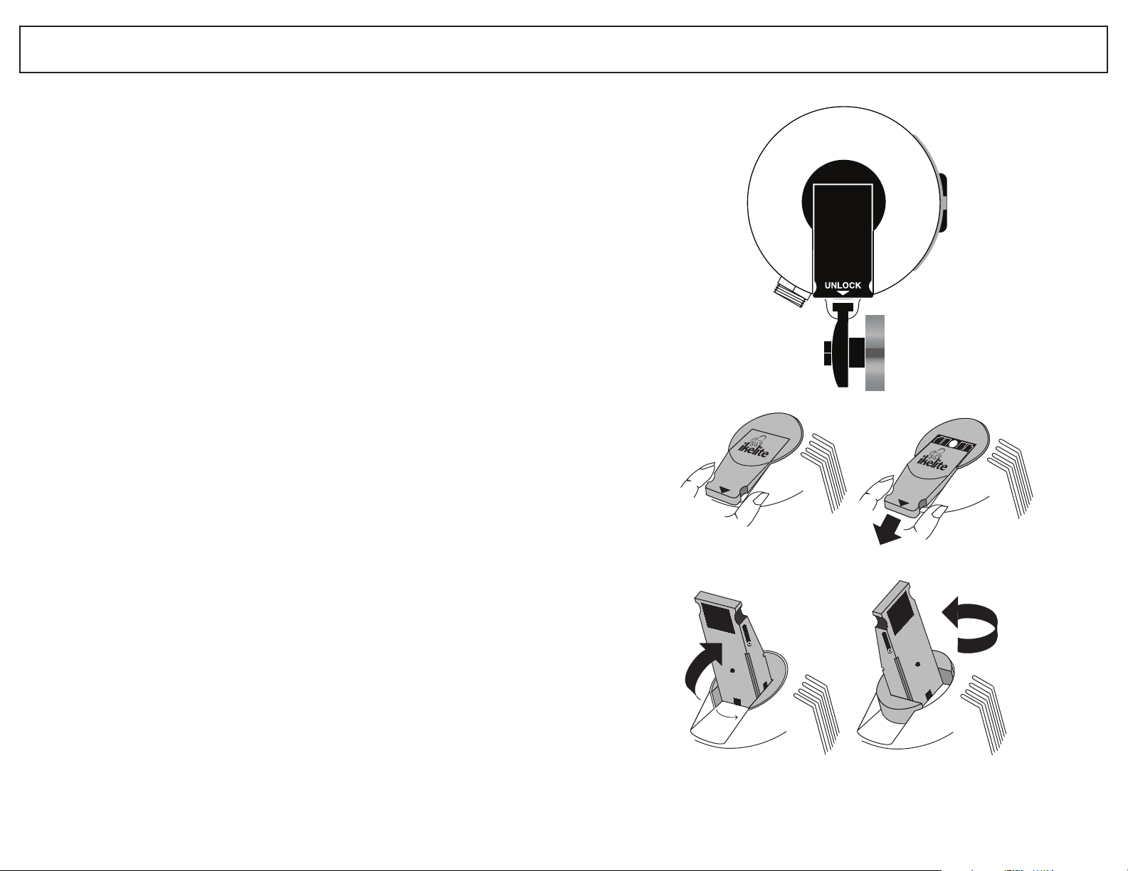
OPENING THE LITE
Pull Out
Flip Up Rotate
SSWWIITTCCHHEESS // FFUUEELL GGAAUUGGE
E
FFUUEELL GGAAUUGGEE________________________________________________________________________________________________________________
When the switch is rotated to the TEST position, the fuel gauge on the side of the
strobe will display 0, 1, 2, or 3 red LED lights indicating the remaining charge in the
battery pack (see below). A fully charged NiMH pack will provide at least 250 full power
flashes and all 3 LED's should light. When no LED's are illuminated, then the battery
capacity is low and you may have less than 36 full power flashes remaining. For general
guidelines, refer to the following list:
• 3 LED’s - above 75%
• 2 LED’s - above 50%
• 1 LED - above 25%
• No LED - less then 25%
CCOONNFFIIDDEENNCCEE SSIIGGNNAALL ________________________________________________________________________________________________
The DS125 strobe features a confidence signal indicator light that will glow if the
strobe properly exposes the picture. The #3 LED on the fuel gauge will glow GREEN for
three seconds if the DS125 strobe quenches, indicating that the strobe has provided
proper exposure. This green confidence light illuminates only in the TTL exposure mode.
FFIIRRIINNGG MMOODDEE SSWWIITTCCHH______________________________________________________________________________________________
Multiple firing modes are featured: TTL/Auto and four manual power settings:
Full, 1/2, 1/4, and 1/8.
TTTTLL//AAuuttoo
-
Thru-The-Lens/Auto Exposure:
The camera automatically signals the
strobe to turn off when the exposure is correct. The camera must feature compatible
TTL/Auto exposure to utilize this mode on the DS125 when connected directly to the
camera. (See “Compatible Cameras” and “TTL/Auto Exposure” sections). The TTL/Auto
firing mode MUST be selected when connecting the optional DS Sensor #4100.5 or
FFuullll
-
Full Power Manual Exposure:
EV-Controller #4100.6.
must select the correct exposure manually. Set the camera aperture based on the subject
The strobe fires at full power each time. You
distance (see "Exposure Guide" section).
11//22,, 11//44,, 11//88
manually balance the strobe output for available light. Select 1/2, 1/4, or 1/8 power
when the strobe-to-subject distance is fixed and the manual full power setting would
-
Manual Exposure Modes:
Select the appropriate power setting to
over-expose with the camera aperture you have selected. The difference between
ppoowweerr sseettttiinngg
is one full f-stop; moving from Full power to 1/2 power decreases the light
output by one full f–stop. Changing the power setting does not alter the coverage angle.
eeaacchh
OOPPEENNIINNGG AANNDD CCLLOOSSIINNG
G
55
66
Page 4
D
S125
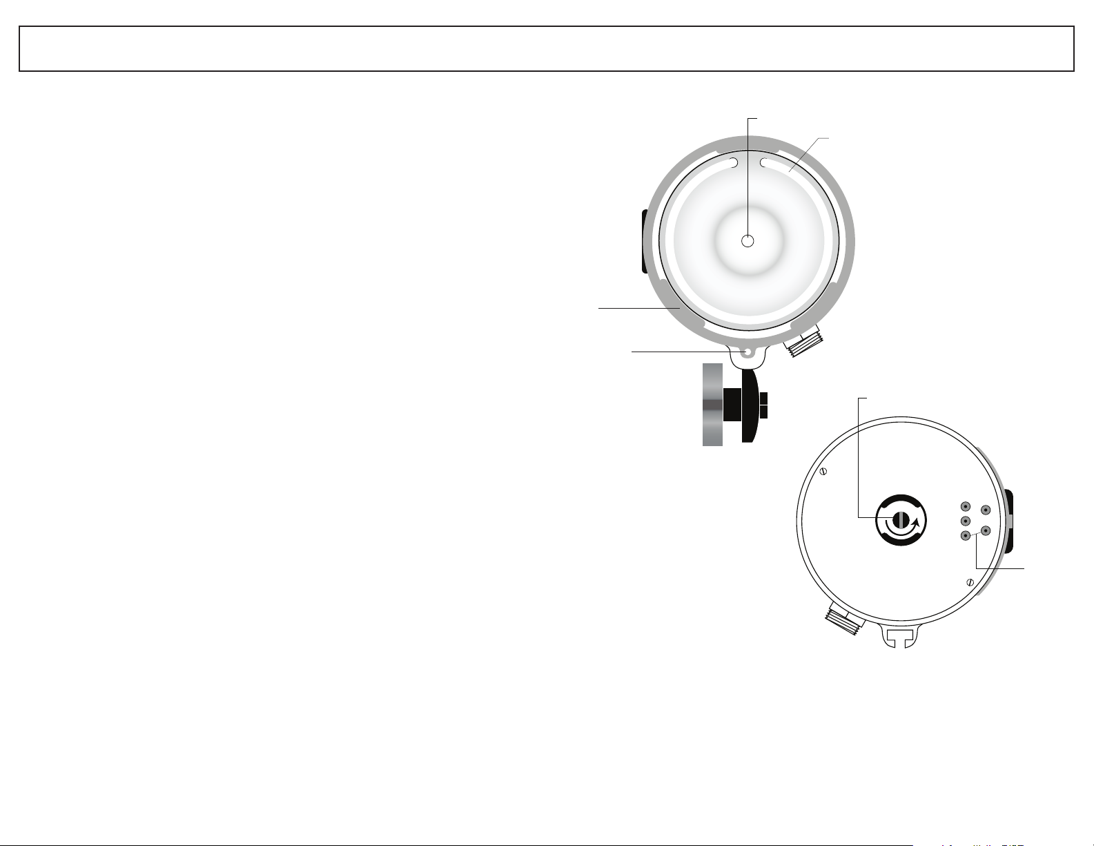
Modeling
Light
Flash
Tube
Flash
Diffuser
Protruding
Ear
Holes
for Lanyard
Tab
Cut-out
Hole for
Diffuser
Lanyard
DS125
Electrical
Pins
Bulb Holder Stem
(unscrew to remove)
OOPPEENNIINNGG AANNDD CCLLOOSSIINNG
G
Always turn the Substrobe OFF before opening the strobe.
OOPPEENNIINNGG TTHHEE SSTTRROOBBEE ____________________________________________________________________________________________
Turn the strobe OFF, and place the strobe face down on a flat surface.
Slide the locking lever out by either grasping the sides of the lever and pulling it out
OR use your thumb to apply slight pressure to the top of the lever and slide it out.
Flip the lever up and then rotate the lever counter-clockwise 90°. The internal
spring automatically pushes open the strobe. Lift the rear section off of the strobe front.
The rear section is the NiMH battery pack for the strobe.
The rear NiMH pack does NOT remain waterproof when removed from the strobe.
Therefore, we suggest keeping the open portion of the NiMH pack pointed down while
removing to eliminate the possibility of water droplets falling inside. The NiMH batteries
remain permanently secured inside the pack.
The front section of the DS125, which houses the main electronics, is safely sealed
separately from the NiMH pack. The front section will remain waterproof when the
NiMH pack is removed. However, avoid salt-water contact with the battery pins.
Damage/corrosion can cause short circuiting.
NiMH pack. We suggest storage of your strobe with the locking lever OPEN to allow
any hydrogen/air mixture
to escape.
DDOO NNOOTT
disassemble the strobe or the
OO--RRIINNGG __________________________________________________________________________________________________________________________
The o-ring is located on the inside rim of the NiMH pack. Keep the o-ring and the
sealing surfaces clean.
lubricate the o-ring. Never use spray lubricant because it may crack the plastic.
RREECCHHAARRGGEE TTHHEE BBAATTTTEERRIIEESS ____________________________________________________________________________________
See "NiMH Pack" section for recharging information.
DDOO NNOOTT
stretch the o-ring when cleaning. It is not necessary to
MMOODDEELLIINNGG LLIIGGHHT
T
CCLLOOSSIINNGG TTHHEE SSTTRROOBBEE ______________________________________________________________________________________________
Make sure the power switch has been rotated to the off position.
Place the front of the strobe face down on a flat surface. Check that the o-ring and
sealing surfaces are clean; make sure the o-ring is positioned properly inside the rim of
the NiMH pack. Place the locking lever in the open position (slide the lever out, flip the
lever up, and rotate the lever counterclockwise).
Align the front and rear sections of the strobe. Lower the NiMH pack onto the front
section of the strobe. Proper alignment of the two sections is extremely important to
avoid possible damage to the internal components.
To seal the strobe, simply press down slightly on the rear of the NiMH pack and
rotate the lever clockwise. Flip the lever down and then slide the lever in to the locked
position to properly seal the strobe.
77
88
Page 5
DS125
Charger
Socket
O'Ring
Electrical
Receptors
MMOODDEELLIINNGG LLIIGGHHT
T
NNiiMMHH BBAATTTTEERRYY PPAACCKK ##44006666..5
5
The modeling light is located in the center of the strobe front; it is ideal as an
aiming light and night diving light. The second ON position turns on both the power
to the Substrobe and the modeling light. Note that the TEST battery position also turns
ON the modeling light as a reminder that the switch is in the TEST position.
It is normal for the modeling light to flicker every few seconds as the strobe
capacitors recharge. The momentary power drain on the batteries causes the flickering
as the strobe recycles.
BBUULLBB ______________________________________________________________________________________________________________________________
The bright 7.2V krypton modeling light bulb #0042.34 draws the equivalent of
under 50 full power flashes per hour.
CCHHAANNGGIINNGG TTHHEE BBUULLBB ______________________________________________________________________________________________
The modeling light bulb is accessed from inside the front section of the strobe. Turn
the strobe off and remove the NiMH pack. Then unscrew the long stem securing the
bulb holder to the rear of the front section, and lift out the bulb holder. Tip the front of
the strobe up and the modeling light bulb will drop out of the strobe.
The o-ring on the bulb holder provides a waterproof seal for the front section. Keep
the o-ring clean. Use only enough lubricant to lightly cover the exposed portion of the
o-ring; wipe off any excess with a clean cloth.
To install the new modeling light bulb, tip the front of the strobe down and
carefully drop the bulb down into the center opening at the rear of the front section.
The bulb will drop into the reflector opening in the strobe. Then replace the bulb holder
in the front section and tighten to secure.
Rechargeable NiMH battery pack #4066.5 is compatible only with Ikelite's DS125
strobe. It is the only battery pack usable in the DS125. The rear section of the strobe
is the NiMH battery pack for the strobe. Additional NiMH packs (rear sections)
#4066.5 are available.
A fully charged NiMH pack provides at least
sub-C-cell industrial grade NiMH batteries (1.8Ah rating).
The NiMH pack does NOT remain waterproof when removed from the strobe.
Therefore, we suggest keeping the open portion of the NiMH pack pointed down
while removing to eliminate the possibility of water droplets falling inside. The NiMH
batteries remain permanently secured inside the pack.
NiMH pack or charger.
225500 ffuullll ppoowweerr ffllaasshheess
DDOO NNOOT
. It consists of six
T
disassemble the
CCHHAARRGGIINNGG TTHHEE NNiiMMHH PPAACCKK ____________________________________________________________________________________
Recharge the NiMH pack after each use.
shortens the battery life. Definitely recharge the NiMHs if the modeling light dims or if the
recycle time exceeds 8-10 seconds; batteries are nearly depleted. Store the NiMH pack fully
charged and recharge the pack for a few hours each month. In our application, the NiMHs
should NOT develop a memory. Fully discharging the NiMHs or allowing the NiMHs to
completely lose a charge does far more damage than any risk of NiMH memory.
DDOO NNOOTT
fully discharge NiMHs as this
AAIIMMIINNGG TTHHEE SSTTRROOBBEE ________________________________________________________________________________________________
Use the modeling light to aim the strobe. Look thru the camera's viewfinder, and
aim the strobe so that the modeling light shines in the center of your picture area. If
your subject distance greatly changes, you should recheck the positioning of the strobe.
When using auto-focus cameras, the modeling light may be required in low light
levels to illuminate your subject to allow the camera to auto focus.
99
1100
Page 6

SSMMAARRTT CCHHAARRGGEERR ##44006666..1
1
SSTTRROOBBEE RREEAADDYY LLIIGGHHT
T
CCAAUUTTIIOON
OOnnllyy uussee 55--66 cceellll IIkkeelliittee NNiiMMHH CChhaarrggeer
SSMMAARRTT CCHHAARRGGEERR ##44006666..11________________________________________________________________________________________
The Smart Charger #4066.1 is a variable input voltage charger that automatically
adjusts for the voltage of the power source, ranging from 100V to 240V. The Smart
Charger adapts to current fluctuations in travel destinations with poorly regulated
power. It provides more complete recharging, prolongs battery life, and offers trickle
maintenance charge.
CChhaarrggiinngg TTiimmee
The Smart Charger will fully recharge the DS125 battery pack in 2 hrs.
SSmmaarrtt CChhaarrggeerr CCoommppoonneennttss
The Smart Charger #4066.1 offers use worldwide by accepting interchangeable
adapter plugs for different electric wall outlets. It is packaged with four interchangeable
charger plugs for USA, European, United Kingdom, and Australian electric outlets.
Choose the appropriate charger plug for your location and slide the chosen plug on the
back of the charger; it snaps into position. To interchange the charger plugs, press UP on
the charger plug to unsnap it from the back of the charger and slide another plug into
position.
SSmmaarrtt CChhaarrggeerr IInnddiiccaattoorr LLiigghhtt
The charge indicator light on the Smart Charger shows the present recharge mode.
It illuminates once connected to both the electric outlet and the Ikelite battery module.
Recharge time with the Smart Charger is 2-hours for a full recharge of the DS125;
afterwards the Smart Charger will automatically switch to provide a trickle maintenance
charge. Only the Smart Charger is capable of providing a trickle maintenance charge
permitting the NiMH pack to be continuously charged for extended periods.
N
r
RREEAADDYY LLIIGGHHTT ______________________________________________________________________________________________________________
The DS125 strobe features a visual ready light on the side of the strobe that glows
when the strobe has recycled and is ready to fire. The middle #2 LED on the fuel gauge
functions as the visual ready light.
CCOONNFFIIDDEENNCCEE LLIIGGHHTT __________________________________________________________________________________________________
The DS125 strobe also features a confidence light that will glow if the strobe
properly exposes the picture. The #3 LED on the fuel gauge will glow GREEN for three
seconds if the DS125 strobe quenches, indicating that the strobe has provided proper
exposure. This green confidence light illuminates only in the TTL exposure mode.
CCOONNTTIINNUUOOUUSS iilllluummiinnaatteedd lliigghhtt
Indicates that the NiMH module is being quick-charged.
SSLLOOWW BBLLIINNKKIINNGG iilllluummiinnaatteedd lliigghhtt
Indicates that the NiMH module is fully recharged and the charger is now providing
a trickle maintenance charge, which permits the NiMH module to be continuously
charged for extended time periods.
RRAAPPIIDD BBLLIINNKKIINNGG iilllluummiinnaatteedd lliigghhtt
Indicates that the NiMH module was virtually drained (discharged) and the module
is being slow-charged to bring up the NiMHs. Once the NiMHs reach an acceptable
level, then the charger will automatically switch to the quick-charge mode.
1111
1122
Page 7

CCOOMMPPAATTIIBBLLEE CCAAMMEERRAAS
S
TTTTLL // AAUUTTOO EEXXPPOOSSUURRE
E
The Ikelite DS125 strobe is preflash compatible and provides optimum performance
with traditional film cameras, digital still cameras, and dSLR cameras in related Ikelite
housings. The appropriate sync cord or sensor must be connected to trigger the strobe.
TTRRAADDIITTIIOONNAALL FFIILLMM CCAAMMEERRAASS ________________________________________________________________________________
The TTL/Auto exposure mode on the Ikelite DS125 strobe is compatible with the
following TTL film camera systems. The camera reads the light passing thru-the-lens
and automatically signals the strobe to turn off when the exposure is correct.
• SLR 35mm camera in the Ikelite SLR-AF Housing or another brand SLR housing
that features Nikon-based TTL electronics.
• Nikonos V camera
• Nikonos RS camera
DDIIGGIITTAALL SSTTIILLLL AANNDD ddSSLLRR CCAAMMEERRAASS ______________________________________________________________________
TTrriiggggeerreedd vviiaa SSyynncc CCoorrdd
Many Ikelite Digital Still Housings and Ikelite dSLR Housings feature TTL compatible
circuitry connected with the Ikelite female bulkhead connector. Connect the Ikelite sync
cord from the Ikelite housing to the DS125 strobe for TTL auto exposure.
Some other Ikelite housing models may feature the Ikelite bulkhead connector but
offer only manual exposure because TTL conversion circuitry for that specific camera
model may be unavailable or not yet developed.
TTrriiggggeerreedd vviiaa SSllaavvee SSeennssoorr
Some digital still cameras feature a small built-in flash
a sync cord for an external strobe. Most of these cameras fire their built-in flash more
than once while taking a flash picture. This happens so fast it is difficult to see, but the
preflash helps the camera determine focus, exposure and color balance. After the
preflash, the camera’s built-in flash then fires to illuminate the subject and the picture
is taken. For the external strobe to provide proper exposure, it MUST be preflash
compatible to duplicate the preflash sequence. The Ikelite DS125 strobe is a
ccoommppaattiibbllee
Ikelite DS Sensor #4100.5 may be compatible to trigger the DS125 strobe. Built-in slave
sensors in the DS Sensor detect the light output from the camera’s built-in flash and
automatically signal the DS125 strobe to mimic the output by starting and stopping
automatically. However, some of the newest digital still cameras feature a preflash
sequence too quick for the Ikelite DS Sensor to identify proper auto exposure, and the
Ikelite EV-Controller #4100.6 would then be recommended instead.
EV-Controller #4100.6, which connects to the DS125 strobe and provides 10-manual
power settings in half-stop increments. The EV-Controller can be triggered using the
built-in slave sensor or by connecting an optional sync cord.
strobe.
For those cameras that do not offer a means to connect a sync cord, the optional
For maximum control using manual exposure, choose the optional Ikelite
wwiitthhoouutt
a means to connect
pprreeffllaasshh
Most newer cameras and strobes feature TTL/Auto exposure, which automatically
compensates for aperture, distance, extension tubes, and filters. Considering the wide
range of apertures and subject distances, select the TTL/Auto exposure mode to easily
control balanced lighting and close-up photography.
When the strobe fires, the camera reads the light and automatically signals the
strobe to turn off when the exposure is correct. Both the strobe and camera must
feature TTL/Auto exposure compatible electronics. The appropriate TTL sync cord or
optional Ikelite DS Sensor is required to relay the TTL/Auto exposure signal from the
camera to the strobe.
Please review the "Compatible Camera" section on the previous page for additional
information.
TTTTLL SSYYNNCC CCOORRDDSS ________________________________________________________________________________________________________
Ikelite offers interchangeable sync cords so that different camera systems can be
connected to the DS125 strobe. A TTL sync cord is required to send the TTL/Auto
exposure signal from the camera to the strobe.
DDSS SSEENNSSOORR ##44110000..55 __________________________________________________________________________________________________
The Ikelite DS Sensor provides auto exposure functions through slave sensors
enabling the Ikelite Substrobe to be moved freely and positioned virtually anywhere.
The DS Sensor connects only to Ikelite DS Substrobes and detects when the light from
the TTL strobe connected to the camera starts and stops, and automatically signals the
Ikelite Substrobe to start and stop in sync.
Many digital still cameras feature a small built-in flash without a means to connect
a sync cord for an external strobe. For these situations, the optional Ikelite DS Sensor
#4100.5 may be compatible to trigger the DS125 strobe. The sensor detects the light
output from the camera’s built-in flash and automatically signals the DS125 strobe to
mimic the output. Some of the newest digital still cameras feature a preflash sequence
too quick for the Ikelite DS Sensor to identify proper auto exposure, and the Ikelite
EV-Controller #4100.6 would then be recommended instead.
RRAAPPIIDD UUSSE
The DS125 strobe should NOT be continuously fired more than 15 times in rapid
succession. In such instances, allow the DS125 strobe to cool off for at least 10 minutes.
E
1133
1144
Page 8

Bulkhead
Connection
Stem O’ring
Retaining
Ring
Ikelite
CCAAMMEERRAA RREEAADDYY LLIIGGHHT
TTrriiggggeerreedd vviiaa SSyynncc CCoorrdd
When using a TTL/Auto exposure camera (film or digital) in an Ikelite TTL-compatible
housing connected to the DS125 strobe by sync cord, the flash ready light in the camera
viewfinder and the DS125 ready light will both glow when the Substrobe has recycled and
is ready to fire.
If the Ikelite housing does not feature TTL compatible circuitry, then the ready light
in the camera viewfinder would not be triggered when the strobe has recycled.
TTrriiggggeerreedd vviiaa SSllaavvee SSeennssoorr
When using the DS125 strobe with the optional DS Sensor or EV-Controller (without
optional sync cord), the strobe is not electronically connected to the camera. Therefore,
the ready light in the viewfinder of the camera indicates when the on-camera flash has
recycled. Reference both the camera and DS125 ready lights to make sure both flashes
have fully recycled before taking the next picture.
T
SSTTRROOBBEE CCOONNNNEECCTTIIOON
N
1155
1166
Page 9

Retaining
Ring
Stem O-ring
Ikelite
Index Groove
Stem O-ring
Retaining
Ring
Nikonos
SSTTRROOBBEE CCOONNNNEECCTTIIOON
N
SSYYNNCC CCOORRDDS
S
The female Ikelite bulkhead connector on the strobe permits different Ikelite sync
cords or the Ikelite DS Sensor or EV-Controller to be connected. The sync cord or sensor
relays the trigger signal to the Substrobe.
The removable waterproof cap seals the bulkhead connector when neither the cord
nor the sensor is connected. The strobe bulkhead connector must be sealed to remain
waterproof.
•• DDOO NNOOTT
DDOO NNOOTT
•
periods as electrolysis can make removal impossible.
DDOO NNOOTT
•
or when wet. Connections are NOT waterproof when not connected.
use TTL cord with a non-TTL Substrobe; you will damage the camera.
leave the sync cord or sensor connected to the strobe for
disconnect the sync cord or sensor from the strobe while underwater
prolonged
CCOONNNNEECCTTIIOONN TTOO SSTTRROOBBEE________________________________________________________________________________________
Connect either the sync cord or sensor to the Substrobe in the same manner.
TThhee ccoonnnneeccttoorr tthhrreeaaddss aarree vveerryy ffiinnee;; DDOO NNOOTT ccrroossss tthhrreeaadd.
IIff iitt iiss ddiiffffiiccuulltt ttoo ttuurrnn,, yyoouu aarree ccrroossss tthhrreeaaddiinngg.
1. Turn the Substrobe OFF and make sure all components are dry. Clean and lightly
lubricate the stem o-ring and the strobe bulkhead connector threads. Check o-ring for
nicks or cuts. Never use spray lubricant.
2. Note the positioning of the receptacles and pins. Properly align the end of the
cord and insert into the strobe bulkhead connector. When using the #4103.51 cord,
which connects an Ikelite housing to an Ikelite Substrobe, both cord ends are identical;
either end can be connected to the strobe.
3. Hand-tighten the knurled retaining ring on the cord. Push the connector body
further into the bulkhead connector and continue to tighten the knurled ring.
.
.
DDOO NNOOTT
•
DDOO NNOOTT
•
periods as electrolysis can make removal impossible.
DDOO NNOOTT
•
when wet. Connections are NOT waterproof when not connected.
use TTL cord with a non-TTL Substrobe; you will damage the camera.
leave the sync cord connected to the camera or strobe for prolonged
disconnect the sync cord from the camera or strobe underwater or
TThhee ccoonnnneeccttoorr tthhrreeaaddss aarree vveerryy ffiinnee;; DDOO NNOOTT ccrroossss tthhrreeaadd.
IIff iitt iiss ddiiffffiiccuulltt ttoo ttuurrnn,, yyoouu aarree ccrroossss tthhrreeaaddiinngg.
.
.
LLUUBBRRIICCAANNT
• Use only Ikelite brand silicone lubricant with Ikelite brand o-rings as other
lubricants can cause the Ikelite o-rings to swell in size.
DDOO NNOOTT
•
• Ikelite silicone lubricant is provided for the cord o-ring. Use only enough
to lightly cover the o-ring; wipe off any excess with a clean cloth.
•
Lubricant only reduces friction; it is NOT a sealant.
use spray lubricant as it may cause cracking of the plastic.
T
1177
brand
lubricant
LLUUBBRRIICCAANNT
• Use only Ikelite brand silicone lubricant with Ikelite brand o-rings as other
brand lubricants can cause the Ikelite o-rings to swell in size.
DDOO NNOOTT
•
lubricant is provided for the sync cord o-ring. Use only enough lubricant to lightly
cover the o-ring; wipe off any excess with a clean cloth.
• Lubricant only reduces friction; it is NOT a sealant.
use spray lubricant as it may cause cracking of the plastic.Ikelite silicone
T
1188
Page 10

..........
..........
..........
..........
..........
........
.....
..........
SUBSTROBE DS125
FILM ISO RATING
DISTANCE
M
M
M
M
M
M
M
M
0.3 0.6 1.2 2.5 5m
1
2
4
8
16ft
25 50 100 200 400 800
25 50 100 200 400 800
2.8 4 5.6
2.8 4 5.6 8
2.8 4 5.6 8 11
2.8 4 5.6 8 11 16
4 5.6 8 11 16 22
5.6 8 11 16 22
8 11 16 22
11 16 22
CCAAMMEERRAA CCOONNNNEECCTTIIOON
N
EEXXPPOOSSUURREE GGUUIIDDE
E
IIKKEELLIITTEE TTTTLL CCOORRDDSS ____________________________________________________________________________________________________
##44110033..5511
Single strobe cord
These cords connect Ikelite Substrobes to Ikelite camera housings. Use TTL/Auto
or manual exposure modes.
CCoonnnneecctt IIkkeelliittee HHoouussiinngg
1. Make sure all components are dry. Clean and lightly lubricate the stem o–ring
and the housing connector threads. Check the o-ring for nicks or cuts.
2. Note the positioning of the receptacles and pins. Properly align the end of the
sync cord and insert into the housing connector. When using the #4103.51 cord,
both cord ends are identical; either end can be connected to the housing.
3. Hand-tighten the knurled retaining ring on the cord. Then push the connector
body further into the housing connector and continue to tighten the knurled ring.
##44110033..5522
Dual strobe cord
NNIIKKOONNOOSS TTTTLL CCOORRDDSS FFOORR FFIILLMM CCAAMMEERRAASS ________________________________________________________
##44110044..66
Single strobe cord
These cords connect Ikelite Substrobes to Nikonos IV, V and RS cameras, and non-Ikelite
housings for traditional film cameras (see next section if using a non-Ikelite housing for a
digital camera). Use either TTL/Auto or manual exposure modes with the Nikonos V / RS
or suitable TTL/Auto exposure camera housing. When using the Nikonos IV or a non-TTL
housing, set the strobe in the manual mode.
CCoonnnneecctt NNiikkoonnooss CCaammeerraa
1. Mount the camera tray underneath the Nikonos camera. Make sure all
components are dry. Clean and lightly lubricate the stem shaft, o-ring, and
retaining ring threads. Check the stem o-ring for nicks or cuts.
2. Align the index groove with the white dot of the camera flash socket, and insert
the stem into the camera socket.
3. Rotate the retaining ring counterclockwise until it mates with the camera socket
threads. Then carefully rotate the retaining ring clockwise and thread it into the
camera body until snug.
CChheecckk CCoonnnneeccttiioonn ffoorr NNiikkoonnooss VV && RRSS
Turn ON the strobe and place camera in the TTL mode. Advance the camera to
frame #1 and the ISO dial to 800 or above. The camera's ready light will blink if the
connection is good. Afterwards, reset ISO dial for the correct film speed.
NNIIKKOONNOOSS CCOORRDDSS FFOORR DDIIGGIITTAALL CCAAMMEERRAASS __________________________________________________________
##44110044..3311
Other brand housings for digital still and dSLR cameras do not offer TTL compatible
circuitry so only manual exposure is offered for the Ikelite Substrobes. Select the non-TTL
Nikonos cord #4104.31 or #4104.32 for compatibility when connecting to the Nikonos-style
female socket on the non-Ikelite housing. Follow the procedure referenced above to connect
the Nikonos cord to the housing.
Single strobe cord
##44110044..6622
##44110044..3322
Dual strobe cord
Dual strobe cord
1199
The purpose of a strobe is to illuminate the subject and bring out the subject's true
colors. Due to the loss of color when light passes through water, move in on your subject
to photograph thru as little water as possible.
The maximum recommended lighting distance underwater with any brand strobe is
1.8m (6'). Selecting a subject at a greater distance underwater will provide mainly bluish
color silhouette type images.
EEXXPPOOSSUURREE LLAABBEELL ______________________________________________________________________________________________________
The exposure label information is primarily intended for use with traditional film
cameras since digital still cameras may require less light for proper exposure. The
exposure label is compatible with TTL/Auto and Manual modes and references the
DS125 strobe output without the diffuser installed.
TTTTLL//AAuuttoo MMooddee eexxaammppllee
for 100 ISO film speed:
If you select f-8, you can shoot subjects up to 1.2m (4’) away.
If you select f-4, you can shoot subjects up to 2.5m (8') away; however, underwater
we recommend selecting subjects no farther than 1.8m (6') away.
FFuullll PPoowweerr MMaannuuaall MMooddee eexxaammppllee
for 100 ISO film speed:
If you select f-8, the subject should be 1.2m (4’) away for proper exposure as
indicated by the letter MM.
11//44 PPoowweerr MMaannuuaall MMooddee eexxaammppllee
The difference between
eeaacchh ppoowweerr sseettttiinngg
for 100 ISO film speed:
is one full f-stop; therefore, moving
from Full to 1/4 power decreases the light output by two full f–stops. If you select
f-8, then reference two less f-stops (two numbers greater) than f-8 in the chart,
which is f-16. Subject should be 0.6m (2’) away for proper exposure.
CCAAMMEERRAA AAPPEERRTTUURREE __________________________________________________________________________________________________
For balanced lighting between your subject and the background, meter the
available light and set the camera aperture accordingly. Using a
darkens the background. A
wider aperture
lightens the background.
narrower aperture
2200
Page 11

Strobe Mount
Wing Nut
Rubber
Gaskets
Ikelite
Substrobe
Release Button
Stem
Strobe Arm
Release Handle
Knuckle
Knuckle
Arm
Wing Nut
DDIIFFFFUUSSEERR ##00559911..3
D
S125
Modeling
Light
Flash
Tube
Flash
Diffuser
Protruding
Ear
Holes
for Lanyard
Tab
Cut-out
Hole for
Diffuser
Lanyard
3
The white diffuser can be secured to the front of the DS125 strobe when softer
lighting or coverage greater than 90° is desired. The diffuser reduces the strobe output
by one full f-stop while increasing the coverage angle to 100°.
DDIIFFFFUUSSEERR IINNSSTTAALLLLAATTIIOONN ________________________________________________________________________________________
1. The diffuser features three protruding ears for use in installation and removal.
The protruding ears on the diffuser should be positioned away from the strobe.
2. Note the three cut-outs around the perimeter of the diffuser and the three tabs inside
the perimeter of the DS125 strobe front. Place the diffuser over the front of the
strobe, and rotate the diffuser so that the cut-outs align with the tabs on the front.
Insert the diffuser thru the tabs, and then rotate the diffuser so the tabs on the front
lock the diffuser in place.
3. To remove the diffuser, rotate the diffuser so the cut-outs align with the tabs on the
front. Grasp the protruding ears on the diffuser to remove.
4. A lanyard can be attached to the diffuser by threading it thru the two circular
openings on the diffuser.
UUSSEE OOFF TTHHEE DDIIFFFFUUSSEERR ______________________________________________________________________________________________
The diffuser reduces the light intensity by one full f-stop. When referencing the
For the
TTTTLL//AAuuttoo eexxaammppllee
to the strobe with the camera set at f-8, then reference one less f-stop (one
exposure guide information on the previous page, reference one less f-stop (one number
greater) when the diffuser is secured to the DS125.
you can shoot subjects up to 1.2m (4’) away as stated on the previous page. If you
tthhee ddiiffffuusseerr
number greater) than f-8 in the chart which is f-11, meaning you can shoot subjects up
to 0.9m (3’) away.
with ISO 100 film, if you select f-8
wwiitthhoouutt
the diffuser,
aadddd
2211
2222
Page 12

Wing Nut
Ball Clamp
Strobe
Mount
Release Button
Stem
Release Handle
Ikelite
Substrobe
Ball Socket
Ball
Clamp
Wing
Nut
Ball
Socket
MMOOUUNNTTIINNGG TTHHEE SSTTRROOBBE
E
IIKKEELLIITTEE AARRMM SSYYSSTTEEMMSS ______________________________________________________________________________________________
Ikelite offers several arm choices compatible with the DS125. The arm is NOT
supplied with the strobe unless purchased as part of a complete package.
Ikelite arm systems are designed for underwater use and may not hold the
adjustment ABOVE WATER due to the weight of some large strobes. Be careful when
transporting the system since some camera trays may not be able to support the weight
of the strobe above water.
The strobe will feature either a paddle-type or ball-type mount on the underneath
side. Please read the following arm sections for additional information.
SSTTRROOBBEE AARRMM ##44007755..1
The versatile Ikelite Strobe Arm offers multiple aiming positions. A second arm
section with second joint can be added if desired, #4076.2
MMOOUUNNTT SSTTRROOBBEE TTOO AARRMM ________________________________________________________________________________________
The paddle-type strobe mount may be featured on the DS125 and secures to most
Ikelite arm systems. The paddle-type mount is required for compatibility with the arm
4075.1 and it allows the strobe to tilt forward and backward. The rubber gasket on the
strobe mount creates friction against the arm and should NOT be lubricated.
gasket on the strobe mount. Replace the wing nut and tighten to secure. This
adjustment allows the strobe to pivot at the top of the arm. Rubber gasket creates
friction to hold the adjustment underwater and should NOT be lubricated.
Remove wing nut from strobe mount. Place the top of the arm against the rubber
1
MMOOUUNNTT AARRMM TTOO HHOOUUSSIINNGG ____________________________________________________________________________________
The stem protruding at the base of the arm snaps into the release handle on the
Ikelite housing. The stem also provides a convenient location for securing the optional
DS Slave Sensor or EV-Controller.
Insert the stem into the release handle. Depress the handle's release button and slide
the stem fully into the receptor. Release the button and it should spring back to the
original position locking the arm in place.
AAIIMM TTHHEE SSTTRROOBBEE________________________________________________________________________________________________________
Loosen the large four-lobed knob on the knuckle and insert the arm tube. The arm
can be rotated 360°, pivoted sideways, and also rotated forward and backward before
retightening the knob.
2233
2244
Page 13

BBAALLLL--SSOOCCKKEETT AARRMM ##44008866..661
A B C D E F G H I J K L
1
IIKKEELLIITTEE BBAALLLL--SSOOCCKKEETT CCOOMMPPOONNEENNTTS
S
The articulating Ikelite ball-socket arm secures the DS51 strobe to the contoured
release handle on an Ikelite Digital Still Housing or SLR Housing. The dual ball sockets on
the arm are especially versatile for macro photography since they adjust independently
for a multitude of strobe mounting positions.
The ball-socket arm #4086.61 utilizes 2.5cm (1") diameter balls. Optional
components are available as referenced on the following page to modify the arm.
MMOOUUNNTT SSTTRROOBBEE TTOO AARRMM ________________________________________________________________________________________
bbaallll--ttyyppee
A
slides into the underneath side of the strobe body, and permits the use of the ball clamp
at the base of the strobe.
If another mount is already secured underneath the strobe, loosen the screw and
remove the original mount from the strobe. On the ball-type strobe mount, there is a
screw opening at each end. Select the side that has the screw opening nearest the center,
slide this end into the base of the strobe, and secure with the screw.
strobe mount is featured at the top of the ball-socket arm. This mount
MMOOUUNNTT AARRMM TTOO HHOOUUSSIINNGG ____________________________________________________________________________________
The stem protruding at the base of the arm snaps into the release handle on the
Ikelite housing. The stem also provides a convenient location for securing the optional
DS Slave Sensor or EV-Controller.
Insert the stem into the release handle. Depress the handle's release button and
slide the stem fully into the receptor. Release the button and it should spring back to
the original position locking the arm in place.
BBAALLLL CCLLAAMMPPSS ______________________________________________________________________________________________________________
Loosen the wing nut on the ball clamps to adjust the positioning of the arm. Each
section pivots and rotates 360° before tightening the wing nut.
The center cap limits the movement of the wing nut so that the arm cannot be
accidentally disassembled. Adjust the center cap as desired.
BBAALLLL--SSOOCCKKEETT CCOOMMPPOONNEENNTTSS
This page illustrates the range of
interchangeable components available
to add onto the Ikelite Ball-Socket
Arm #4086.61.
Note: Tray mounts are offered for
Ikelite, Univeral, and Dovetail systems.
A variety of Ikelite arm component utilizing 2.5cm (1”) or 3.2cm (1.25”) diameter
balls are available and can be combined with the ball-socket systems of TLC, Nikon, and
Ultralight that use 2.5cm (1”) balls. See “Ikelite Ball-Socket Components” on page 23 for
more information.
2255
2266
Page 14

IIKKEELLIITTEE BBAALLLL--SSOOCCKKEETT CCOOMMPPOONNEENNTTS
S
RREECCOOMMMMEENNDDAATTIIOONNS
S
[A] QUICK RELEASE HANDLE WITH STROBE MOUNT
#9578.07 18cm (7"), #9578.09 23cm (9"), #9578.15 38cm (15") handle
[B] QUICK RELEASE HANDLE WITH 3.2cm (1.25") BALL
#9581.07 18cm (7"), #9581.09 23cm (9"), #9581.15 38cm (15") handle
[C] BALL WITH STEM
#9571.3: 2.5cm (1") ball with extended stem (snaps into release handle).
#9577.3: 3.2cm (1.25") ball with short stem (snaps into release handle).
#9577.33: 3.2cm (1.25") ball with extended stem (snaps in release handle).
[D] BALL 3.2cm (1.25") WITH STROBE MOUNT
#9579.04 10cm (4"), #9579.06 15cm (6"), #9579.12 30cm (12") arm
[E] BALL-TO-BALL ARM EXTENSION
#0466.42: Both balls 2.5cm (1"), arm length 10cm (4")
#0466.62: Both balls 2.5cm (1"), arm length 15cm (6")
#0466.92: Both balls 2.5cm (1"), arm length 22cm (9")
#9580.04: Both balls 3.2cm (1.25"), arm length 10cm (4")
#9580.06: Both balls 3.2cm (1.25"), arm length 15cm (6")
#9580.12: Both balls 3.2cm (1.25"), arm length 30cm (12")
Ball-to-ball adapter #0466.51: Combine different diameter ball arms.
One 2.5cm (1") ball connected to one 3.2cm (1.25") ball, length 13cm (5").
[F] BALL CLAMP
#9571.2: For arm components featuring 2.5cm (1") balls.
#9571.23: For arm components featuring 2.5cm (1") balls,
also features mounting stud extension usable for mounting the
optional Ikelite DS Sensor or EV-Controller.
#9577.2: For arm components featuring 3.2cm (1.25") balls.
[G] IKELITE TRAY MOUNT
#9577.71: 2.5cm (1") ball with tray mount for Ikelite tray/handle.
#9577.1: 3.2cm (1.25") ball with tray mount for Ikelite tray/handle.
[H] UNIVERSAL MOUNT #9577.5: 3.2cm (1.25") ball with shoe mount.
[I] DOVETAIL TRAY MOUNT #9577.7: 3.2cm (1.25") with dovetail mount.
[J] NIKONOS MOUNT #9577.6: 3.2cm (1.25") with Nikonos IV/V shoe.
[K] SUBSTROBE 50, 125 MOUNT: Use ball clamp to secure strobe mount
to ball-socket arm.
#9571.4: 2.5cm (1") ball with mount for DS50, SS50, DS125 strobe.
#9577.41: 3.2cm (1.25") ball with mount for DS50, SS50, DS125 strobe.
[L] SUBSTROBE 100A, 200 MOUNT: Use ball clamp to secure strobe mount
to ball-socket arm.
#9577.43: 2.5cm (1") ball with mount for SS100A, SS200 strobe.
#9577.42: 3.2cm (1.25") ball with mount for SS100A, SS200 strobe..
VVIISSUUAALL IINNSSPPEECCTTIIOONNSS ________________________________________________________________________________________________
Visual inspections are important. Take the time to visually inspect the system above
water. An improper seal or loose connection can cause a lot of damage. Always check for
leaks once you place the system in the water.
IINNSSUURRAANNCCEE__________________________________________________________________________________________________________________
We recommend adding an ALL RISK floater to your homeowner's insurance policy in
the event you damage, flood, or lose your camera or strobe. While the Ikelite Substrobe has
a limited warranty against manufacturing defects, it does not cover customer neglect.
TTEECCHHNNIIQQUUEESS ______________________________________________________________________________________________________________
Add a strobe to illuminate the subject and bring out the subject's true colors. Due
to the loss of color when light passes through water, move in on your subject to
photograph thru as little water as possible. The maximum recommended lighting
distance underwater with
distance underwater will provide mainly bluish color silhouette type images.
The white diffuser can be secured to the front of the DS125 strobe when softer
lighting or coverage greater than 90° is desired. The diffuser reduces the strobe output
by one full f-stop while increasing the coverage angle to 100°.
For balanced lighting between your subject and the background, meter the available
light and set the camera aperture accordingly. A
background. A
over or under exposed, an exposure compensation control may be featured on the
TTL/Auto exposure camera that can be adjusted to compensate accordingly.
For more natural looking photos, add a second external strobe to control the
highlights and shadows of your subject. For TTL automatic exposure, both Ikelite strobes
should be connected via dual sync cord whenever possible. If maximum control for
manual exposure is preferred, choose the optional Ikelite EV-Controller #4100.6, which
provides 10-manual power settings in half-stop increments. The EV-Controller can be
triggered using the built-in slave sensor or an optional sync cord can be connected.
Always carry spare batteries. Weak batteries cause many camera and strobe
problems. Prolong the battery life by recharging the NiMH monthly even when not
used. Do not discharge the NiMH completely as this can cause permanent damage.
wwiiddeerr aappeerrttuurree
aannyy bbrraanndd ssttrroobbee
lightens the background. If the exposures are consistently
is 1.8m (6'). Selecting a subject at a greater
nnaarrrroowweerr aappeerrttuurree
darkens the
RRAAPPIIDD UUSSEE ____________________________________________________________________________________________________________________
The DS125 strobe should NOT be continuously fired more than 15 times in rapid
succession. In such instances, allow the DS125 strobe to cool off for at least 10 minutes.
2277
2288
Page 15

Ikelite
Nikonos
MMAAIINNTTEENNAANNCCE
E
TTRROOUUBBLLEESSHHOOOOTTIINNG
G
The Ikelite SUBSTROBE should be given the same care and attention as your other
photographic equipment. In addition to normal procedures, we strongly recommend that
this strobe be returned to Ikelite periodically to be checked and pressure tested.
1. We suggest storage of your Substrobe with the locking lever OPEN to allow any
hydrogen/air mixture to escape.
2. Always rinse the exterior of the Substrobe with fresh water after use. The strobe
can be cleaned by soaking it in a mild soapy solution. Use liquid soap; RINSE and DRY
the strobe before storage.
3. The o-ring #0132.36 is located on the inside rim of the DS125 battery pack. Keep
the o-ring and the sealing surfaces clean.
It is not necessary to lubricate the o-ring. Never use spray lubricant because it may
crack the plastic.
4. Keep the strobe bulkhead connector threads clean and lightly lubricated. Also
keep the sync cord o-ring and threads clean and lightly lubricated.
5.
Recharge the NiMH pack after each use;
because you will shorten the battery life
recharge the pack for a few hours each month.
6.
The strobe is factory sealed;
• Use only Ikelite brand silicone lubricant with Ikelite brand o-rings as other
brand lubricants can cause the Ikelite o-rings to swell in size.
DDOO NNOOTT
•
• Ikelite silicone lubricant is provided for the sync cord o-ring. Use only enough
lubricant to lightly cover the o-ring; wipe off any excess with a clean cloth.
• Lubricant only reduces friction; it is
use spray lubricant as it may cause cracking of the plastic.
DDOO NNOOTT
. Store the NiMH pack fully charged, and
DDOO NNOOT
T
CCAAUUTTIIOON
LLUUBBRRIICCAANNT
NNOOTT
stretch the o-ring when cleaning.
DDOO NNOOT
T
fully discharge the NiMHs
DDOO NNOOTT
disassemble.
disassemble the battery pack.
N
T
a sealant.
SSTTRROOBBEE WWIILLLL NNOOTT FFIIRREE____________________________________________________________________________________________
1. Check the strobe ready light. Turn the strobe OFF and then back ON. Make sure
that the switch has actually clicked into position.
2. Make sure the charger is operating properly and the NiMHs are fully charged.
3. Check the mode switches on the camera and strobe.
4. Check the sync cord connection at the camera and strobe.
5. When using a sync cord between the camera and strobe, disconnect the cord
from the camera, but leave the cord connected to the strobe. Short across the
pins on the end of the cord to test fire the strobe. If you short across the wrong
receptacles on a TTL sync cord, it may damage the Substrobe electronics.
IIkkeelliittee TTTTLL CCoorrdd::
towards you. Short across the center and lower right receptacles.
NNiikkoonnooss TTTTLL CCoorrdd::
and right receptacles.
If the strobe fires, the problem lies somewhere in the camera. Otherwise, return the
strobe to authorized Ikelite personnel.
Position the raised half-circle encompassing the receptacles
Position the indexing groove towards you. Short across the back
DDOO NNOOTT
self-repair.
FFLLAASSHH CCOORRDD CCOONNTTAACCTTSS
FFLLOOOODDIINNG
The DS125 electronics are safely sealed separately from the battery pack. Should the
battery pack flood, flush with fresh water and dry thoroughly. Determine the cause of
flooding. REPLACE THE COMPLETE BATTERY PACK #4066.5. Never re-use batteries
that have been wet. The water could create an internal short circuit at some later date
causing a potential explosion. DO NOT disassemble the strobe, NiMH pack.
Send the strobe head in for service if there is any discoloration of the battery pins.
G
2299
3300
Page 16

SSEERRVVIICCE
E
IIKKEELLIITTEE LLIIMMIITTEEDD WWAARRRRAANNTTYY ________________________________________________________________________________
Ikelite Substrobes are warranted against any manufacturing defects for a period of
two (2) years from the date of purchase. All other Ikelite products are warranted against
any manufacturing defects for a period of one (1) year from the date of purchase.
Defective products should be returned prepaid to Ikelite. Ikelite will, at its discretion,
repair or replace such products, and will return to customer prepaid. All other claims, of
any nature, including but not limited to bulb failure are not covered. Except as
mentioned above, no other warranty expressed or implied, applies to this Ikelite product.
We recommend adding an ALL RISK floater to your homeowner's insurance
policy in the event you damage, flood, or lose your camera or strobe.
Ikelite warranty does NOT cover customer neglect.
RREETTUURRNNIINNGG PPRROODDUUCCTTSS FFOORR SSEERRVVIICCEE __________________________________________________________________
Ikelite is most interested in performing any service to assure that all products
perform as intended. For repair service, return the Ikelite product to the address below
with your name, address, phone number, and a brief description of the problem.
Evidence of purchase date must be provided to obtain warranty service. Thank you.
IIKKEELLIITTEE UUNNDDEERRWWAATTEERR SSYYSSTTEEMMSS
50 West 33rd Street
P.O. Box 88100
Indianapolis, IN 46208 USA
317.923.4523
IIKKEELLIITTEE UUNNDDEERRWWAATTEERR SSYYSSTTEEMMSS
50 West 33 Street
P.O. Box 88100
Indianapolis, IN 46208 USA
317.923.4523
wwwwww..iikkeelliittee..ccoomm
Email: ikelite@ikelite.com
3311
wwwwww..iikkeelliittee..ccoomm
Email: ikelite@ikelite.com
4065-06-0606
 Loading...