

INSTRUCTION MANUAL
Ikegami Electronics (U.S.A), Inc.
Hybrid Camera
MODEL
IHD-D525S
OUTDOOR USE WARING
WARNING – TO PREVENT FIRE OR
ELECTRIC SHOCK, DO NOT EXPOSE
THIS APPLIANCE TO RAIN OR
MOISTURE.
The apparatus shall not be exposed to
dripping or splashing and that no
objects filled with liquids, such as
vases, shall be placed on the
apparatus.
e
c
o
p
r
s
t
c
u
d
o

Thank you for choosing this Ikegami Hybrid Camera.
Please read this Instruction Manual carefully to keep your Ikegami camera at
peak performance for longer service period.
This unit is a dome-type 1 CMOS color camera and making use of a 1/2.9” sensor.
This Ikegami product is made of ECO friendly components based upon the
Company policy and corporate social responsibility to contribute towards the
Global Environmental Solution for energy conservation and environmental
sustainability, all the comp
Free, Non-Lead and conform with Japan's Green Product regulation, EU's RoHS
directive and other Environmental and hazardous chemical substances related
regulations and laws.
one
nts used in this product are Non-hazardous, Toxic
Contents
Page
1. Handling Precautions ..................................................................E-1
2. General ........................................................................................E-1
3. Features .......................................................................................E-2
4. Camera Installation .....................................................................E-3
4-1. Pre-work before installation ................................................E-3
4-2. Mounting the camera (Ceiling) ...........................................E-3
4-3. Mounting the camera (Wall) ...............................................E-3
5. Name of each section and its function ........................................E-4
6. Connections .................................................................................E-6
6-1. Power cable ........................................................................E-6
6-2. Video output cable (BNC) ...................................................E-6
6-3. Test monitor output (MON.OUT) ........................................E-6
7. Angle and Lens adjustment .........................................................E-7
7-1. Angle adjustment ................................................................E-7
7-2. Vari-focal
l
ens adjustment ..................................................E-7
8. Operating Procedure ...................................................................E-8
8-1. User Setup ..........................................................................E-8
8-2. Names and functions of the setup bottons.........................E-8
8-3. Setup mode Procedures .....................................................E-8
9. Warranty and after-sale service ..................................................E-15
10. Specifications ..............................................................................E-16
11. External Appearance
12. Setup Flow Chart
The exclamation point within an equilateral triangle is intended to alert the user to
the presence of important operating and maintenance (servicing) instructions in the
literature accompanying the appliance.
NOTE:
This equipment has been tested and found to comply with the limits for a Class A digital
device, pursuant to part 15 of the FCC Rules. These limits are designed to provide
reasonable protection against harmful interference when the equipment is operated in a
commercial environment. This equipment generates, uses, and can radiate radio frequency
energy and, if not installed and used in accordance with the instruction manual, may cause
harmful interference to radio communications. Operation of this equipment in a residential
area is likely to cause harmful interference in which case the user will be required to
correct the interference at his own expense.
CAUTION;
ANY CHANGES OR MODIFICATIONS NOT EXPRESSLY APPROVED BY THE PART
RESPONSIBLE FOR COMPLIANCE COULD VOID THE USERS AUTHORITY TO
OPERATE THE EQUIPMENT.
Instructions for Disposal of Electrical and Electronic Equipment in Private
Households
Disposal of used Electric and Electronic Equipment
(Applicable in the European Union and other European countries with
separated waste disposal and collection methods)
This symbol on the product, or in the related documents in the package, indicates
product shall not be treated as normal household waste. Instead, it should
that this
be taken to a proper applicable collection point or depot for the recycling of electric
By ensuring this product is disposed of correctly, you will help prevent possible negative
consequences for the environment and human health, which could otherwise be caused by
inappropriate waste handling of this product. The recycling of materials will help to conserve n atural
resources.
For more detailed information about recycling of this product, please contact your local city
authority, your household waste disposal service or the place where you purchased the product.
and electronic equipment.

IMPORTANT SAFETY INSTRUCTIONS
1) Read these instructions.
2) Keep these instructions.
3) Heed all warnings.
4) Follow all instructions.
5) Do not use this apparatus near water.
6) Clean only with a dry cloth.
7) Do not block any of the ventilation openings. Install in accordance with the
manufacturer's instructions.
8) Do not install near any heat sources such as radiators, heat registers,
stoves, or other apparatus (including amplifiers) that produce heat.
9) Do not defeat the safety purpose of the polarized or grounding type plug. A
polarized plug has two blades with one wider than the other. A grounding
type plug has two blades and a third grounding prong. The wide blade or the
third prong is provided for your safety. When the provided plug does not fit
into your outlet, consult an electrician for replacement of the obsolete outlet.
10) Protect the power cord from being walked on or pinched particularly at plugs,
convenience receptacles, and the point where they exit from the apparatus.
11) Only use the attachments/accessories specified by the manufacturer.
12) Use only with a cart, stand, tripod, bracket, or table specified by the
manufacturer, or sold with the apparatus. When a cart is used, use caution
when moving the cart/apparatus combination to avoid injury from tip-over.
13) Unplug this apparatus during lightning storms or when unused for long
periods of time.

14) Refer all servicing to qualified service personnel. Servicing is required when
the apparatus has been damaged in any way, such as power supply cord
or plug is damaged, liquid has been spilled or objects have fallen into the
apparatus, the apparatus has been exposed to rain or moisture, does not
operate normally, or has been dropped.
15) CAUTION - These servicing instructions are for use by qualified service
personnel only. To reduce the risk of electric shock, do not perform any
servicing other than that contained in the operating instructions unless you
are qualified to do so.

1. Handling Precautions
• Do not expose the internal mechanism of the camera in a water-splashed
or highly humid environment.
• Do not use the camera where the ambient temperature drops below
-10°C or rises above +50°C. The images and component parts may be
adversely affected or the camera may not function correctly.
• Do not open the case of the camera, unless it is absolutely necessary
for setup or installation because there are precision electrical and
electronic components inside and acciden
• Be sure to turn off the power before installing or making connections.
• Be careful not to drop or give a strong shock to the camera while
transporting it.
• Do not touch the image sensor
• Do not orientate the camera directly towards the sun.
• Because of the digital image device characteristics, images may look
unnatural at high temperatures, this does not mean the camera is faulty.
t may
result.
2. General
This color camera is provided with a 1/2.9-inch CMOS sensor. The CCTV
camera features wide
and is equipped with the color/black-and-white switching, back-light
compensation, automatic iris control, line lock and other functions. The
unit is best suited for general surveillance.
dynamic range, high sensitivity and high resolution,
E-1

3. Features
(1) Compact Dome Configuration
The camera lens is housed in a compact dome configuration to enable
surveillance with images without having to be aware that a camera is
installed.
(2) Integrated unit with triaxial adjustment varifocal lens in a single unit
This is an integrated type design featuring a varifocal lens. Because it
can operate with triaxial adjustment, even when attached to a wall, it
can be adjusted to an arbitrary imaging range.
(3) Wide Dynamic Range (CVI,AHD)
The WDR function provides for very effective compensation of high
light and dark areas in screen. This situation may occur generally
outside or viewing from indoor to outdoor scenes. Even in large light
fluctuations, bright-and-dark subjects can be captured and viewed
fl
clearly with a natural appearance.
) High-quality picture and high resolution
(4
The camera is designed for smear-free imaging and low noise. The
well-designed DSP, Digital Signal Processor, effectively enhances
details, which achieves crisp and sharp images with a high signal-to-
noise ratio.
(5) Automatic white balance
Thanks to the automatic follow-up white balance control (ATW), the
white balance adjusts itself no matter how great the subject's color
temperature fluctuates.
(6) Automatic Sensitivity Control
In conju
nction with the wide dynamic control by the multi-sampling
system, the camera incorporates
function that always provides adequate and bright images even
through its fixed-iris lens.
the automatic sensitivity control
E-2
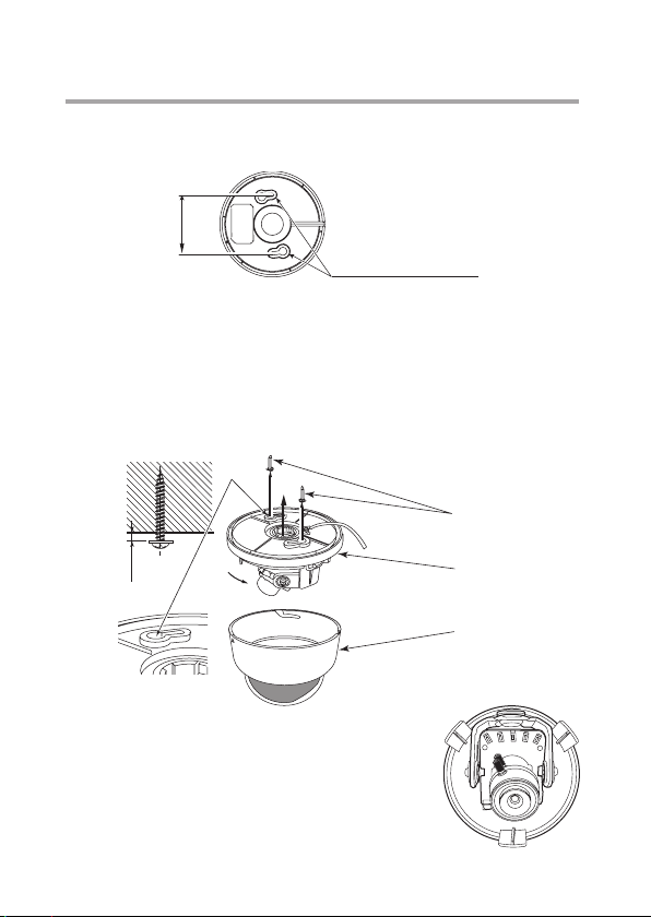
4. Camera Installation
68.5
Holes for camera fixing
5mm
Upper
Lower
4-1. Pre-work before installation
For camera fixing, two holes are needed.
4-2. Mounting the camera (Ceiling)
Put two fixing screws leaving about 5mm clearance. Those two screws
will be tightened later to secure the dome camera. Put the cable wiring
through the center hole of the camera base , and align two key hole slot
to the screws.
And turn the unit clockwise until it stops and tighten two fixing screws. Put
back the dome cover.
②
①
①
Screws
③
4-3. Mounting the camera (Wall)
The way of installation is the almost same as to
a ceiling. Install the main unit so that the switch
becomes upper side as shown in the illustration
right and set the “FLIP” in the setup menu to
“V-FLIP”.
Camera
Dome cover
E-3

5.
Name of each section and its function
③
②
④
⑥
⑤
①
⑦
⑧
E-4

Lens fixing screws (elevation)
①
These are screws to fix the camera in the desired elevation position.
Fix these screws after setting the viewing position.
Vari-focal lens
②
Can be used with flexible angle of view using varifocal lens.
Switches for camera setup
③
Refer to Section 8 (Operating Procedure)
Test monitor output
④
Connect accessory MON.OUT output harness.
⑤
Power cable
This is a power cable. Non-polarity AC24V (AC 21.6V ~ 26.4V) or
DC12V has to be connected. Check the power voltage from the external
power sup
* This installation should be made by a qualified service person and
should conform to all local codes.
Video Output cable (BNC)
⑥
This is the output of video signal. Connect this to a monitor or switcher.
⑦
Fixing holes (two key hole slots)
Dome Cover
⑧
before applying power to the camera.
ply
E-5

6. Connections
Be sure not to apply power before making connections.
6-1. Power cable
Use DC12V (10.5V to 15V), or AC24V (± 10%) in both 60Hz and 50Hz.
* This installation should be made by a qualified service person and
should conform to all local codes.
6-2. Video output cable (BNC)
This is a video output terminal. To be use an ordinary video output, for
monitors, or switcher.
6-3. Test monitor output (MON.OUT)
• Image output terminal used when installing the camera.
• By using the accessory cable to connect
or the image input terminal, it is easier to carry out positioning and
focusing.
to the VIDEO IN of the monitor
E-6

7. Angle and Lens adjustment
Zoom knob
Focus knob
7-1. Angle adjustment
Before doing this, the clear dome cover has to be
removed.
Remove the dome cover
●
Turn the black section of the dome cover in a
counterclockwise direction to remove.
Pay attention not to drop a dome cover while doing
this.
Note:
When imaging in a horizontal direction, the
black section of the dome cover may be imaged
so that part of the image is missing. Adjust the
angle of vision in a horizontal direction so that
the dome cover is not image
7-2. Vari-focal lens adjustment
To re-direct lens, loosen the lens fixing screws for elevation.
Adjust the zoom knob for framing and angle, and a focus knob for
focusing.
Using those two knobs, adjust the lens to have desired framing, angle
and focal point. Repeat this procedure a couple of times, so that you may
achieve the best result.
Once the desired settings have been achieved, tighten the screws to fix
the position.
d.
E-7

8. Operating Procedure
8-1. User Setup
This dome camera is provided with user setup function for picture quality,
and camera ID. The setup menu is a tree type on-screen-display.
When installing the camera it is possible to set up the various functions.
8-2. Names and functions of the setup bottons
UP To select setup parameters
DOWN (up and down)
RIGHT To change setup parameters
LEFT
SET To get in or get out to setup
*
SET UP DOWNRIGHTLEFT
To get into Setup mode, hold SET button
more than 2 seconds.
8-3. Setup mode Procedures
Hold down the SET button longer than 2 seconds, and the setup menu
screen at left appears on screen. A highlighted item is now selected.
Use the LEFT/RIGHT buttons to change the selection items.
mode, and to enter and
execute procedures.
E-8

8-3-1. MAIN MENU
When the OSD menu is launched, you are presented with the adjacent
opening screen.
A menu option followed by a indicates the presence of a sub-menu.
Options set to OFF will not show a until set to ON.
Use RETURN to the previous menu.
MAIN MENU
FOCUS ADJUST
EXPOSURE
BACKLIGHT
DAY&NIGHT
WHITE BAL
DNR
ADJUST
MOTION
SYSTEM
EXIT
(1)FOCUS ADJUST
FOCUS ADJUST is a function to support focus adjustment.
A focus indicator displayed on the screen can be used to confirm
the focus conditions.
OFF
OFF
AUTO
MIDDLE
OFF
SAVE
- From the Main Menu, turn the Focus ADJ from OFF to ON to create
a Focus Adjust Box on the screen’s bottom left
- Move the lens to direct towards the object to be focused, and turn the lens focus
from near to far until the location from the Focus Assist Box shows a green bar.
Next turn the lens focus until the yellow bar has a similar size with the green bar
for focus. Your camera should now have a clear crisp image.
E-9

(2)EXPOSURE
It selects Lens Mode, Brightness, Shutter speed, Sens-up and AGC Gain.
LENS - DC or Manual selection.
①
BRIGHTNESS - Sets the level of the overall.
②
SHUTTER - Auto, Manual, FLK selection, 1/30~1/30K.
③
Set this on to reduce the exposure time of each image.
This can be used to reduce blur in images with fast changing content.
FLK mode use this when flicker is observed in the image
under fluorescent lighting.
④
SENS UP - Slows frame rate and increases low light sensitivity.
AGC- Level Control -Used to adjust overall gain.
⑤
EXPOSURE
LENS
BRIGHTNESS
SHUTTER
SENS-UP
AGC
RETURN
(3)BACKLIGHT
Setting the backlight compensation and light source correction function
are available.
①
WDR - Used to improve contrast in bright/dark areas.
( NOTE : WDR function is only inactive on CVBS output.)
BLC - Adjust the area to be enhanced and sets the level.
②
HLC - It is the ability to reverse bright points to black or gray,
③
(areas such as headlights, any high luminance areas) this function will
improve the overall picture.
DC
10
AUTO
X4
10
E-10

(4)DAY & NIGHT
Selecting Day or Night is available.
AUTO - The image is automatically switched between high-quality
①
color image for the day and highly-sensitive monochrome image
for the night.
COLOR - Fixes the camera in color mode.
②
B/W - Fixes the camera in monochrome mode.
③
EXTERN - This mode which forcibly switches the Day/Night mode using
④
an external input.
(5)WHITE BALANCE
Setting a white balance is available.
①
AUTO
The camera automatically samples the image for optimum
white balance.
AUTOext(default)
②
The camera automatically samples the image for optimum white balance
in an exterior environment.
PRESET
③
Allows the white balance to be set automatically and locked. This option is
normally used when no white reference is present in the image.
To set the white balance, hold a white object in front of the camera,
with light from the source falling on it and press the joystick to set and
lock the white balance.
MANUAL
④
This option allows a selection of color temperature, Red and Blue gain
to be manually set in the image. Note, using this option requires care to
ensure all cameras on one system have the same color response.
WHITE BAL
AWB
RETURN
AUTOext
E-11

(6)DNR(Digital Noise Reduction)
This function is used to improve the picture quality by filtering the noise
which is generated under low light conditions.
(7)ADJUST
Color gain, sharpness, gamma, mirror, flip, ace, defog and privacy are
available.
COLOR GAIN
①
It adjusts the color intensity.
SHARPNESS
②
It adjusts the edge intensity of the video.
GAMMA
③
This function is for compensating the saturation and brightness of
the images shown on the display.
MIRROR
④
It flips the video vertically.
⑤
FLIP
It flips the video horizontally.
ACE(Adaptive contrast enhancer)
⑥
Preserves fine details, reduces artifacts and loss of local contrast
in the image areas of bright/dark.
⑦
DEFOG
Used to help improve the captured image in poor weather conditions
such as smog, fog, or smoke. It automatically controls contrast ratio
by spatially analyzing the histogram characteristics.
⑧
PRIVACY
The maximum 16 privacy masks can be set.
Setting mask color, intensity, and size are available.
ADJUST
COLOR GAIN
SHARPNESS
GAMMA
MIRROR
FILP
ACE
DEFOG
PRIVACY
RETURN
15
0.5
OFF
OFF
OFF
OFF
OFF
E-12

(8)MOTION
ON
MOTION OSD
This function detects and dispalys the object in motion.
DET WINDOWS
①
Select and set up to 4 motion areas.
SENSITIVITY
②
Level control.
TEXT ALARM
③
Display “Motion Alarm” on Screen.
SIGNAL OUT - N/A
④
MOTION
DET WINDOWS
DET TONE
MDDECT FILL
SENSITIVITY
TEXT ALARM
SIGNAL OUT
RETURN
2
ON
5
ON
OFF
E-13

(9)SYSTEM
p
OUTPUT
①
CVBS(default), CVI, AHD Selectable.
FRAME RATE
②
Select from 1080P - 30P or 720P - 30P or 720 - 60P
FREQ
③
60Hz or 50Hz can be seleted.
COM
④
Set com port and speed.
IMAGE RANGE
⑤
Used to adjust black level in dark sceen.
COLOR BAR
⑥
This function is to get the color displayed.
LANGUAGE
⑦
Select from 5 languages.(ENG, CHN, CHN(s), JPN, KOR)
CAMERA TITLE
⑧
The screen can display 8 characters.
RESET
⑨
It returns to the factory default.
OUTPUT
FRAME RATE
FREQ
COM
Image range
COLOR BAR
LANGUAGE
CAMERA TITLE
RESET
RETURN
SYSTEM
1080-30
60Hz
FULL
OFF
ENG
OFF
ON
E-14
OUTPUT
HD ANALOG
RETURN
CVBS

9. Warranty and after-sale service
A warranty accompanies this product. Read and fill out the warranty card
that you have received at your dealer. Keep this card in a safe place.
●Please consult Ikegami Electronics (U.S.A.) Inc. or Ikegami Electronics
(Europe) GmbH o r your dealer for full warranty information. Your dealer
will repair or replace free of charge within the warranty period according
to the warranty coverage.
●For repairs after the expiration of
dealer or sales representative. It will first be judged whether the fault is
repairable or not. Charged servicing will then be made upon request of
the user.
●Before you ask for servicing, please ensure you read the Instruction
Manual. If the unit still fails, take note of the model number, date of
purchase, problem, etc. in detail, and inform your dealer or sales
representative.
●If you have que
or sales representative.
* We suggest you ask for preventive inspection as soon as possible.
stions about the after-sale service, contact your dealer
the warranty period, consult your
E-15

10.
(1) Image Sensor:
(2) HD Resolution:
(3) Scanning system:
(4) Sync system:
(5) Video output:
(6) Day/Night switching:
(7) S/N ratio:
(8) Minimum object illumination:
(9) Wide Dynamic Range:
(10) AGC:
(11) Eletronic shutter:
(12) White Balance Control:
(13) Digital Noise Reduction:
(14) ACE:
(15) DEFOG:
(16) Private Mask Setting:
(17) Camera ID:
(18) Motion Detection:
(19) Operating Temperature
and Relative humidity:
(20) Lens:
(21) Power Requirement:
(22) Power consumption:
2Mega Pixel Cmos Sensor
Full HD (1920 x 1080)
16:9 Progressive scan
Internal
Analog Output-CVBS(default)
HD Output-CVI,AHD(Full HD)
Digital Day/Night
Over 52dB(p-p/rms)
0.08Lx at B/W at Sens up<<off>>
Support (1080p@15fps)
ON/OFF(Variable)
Auto, Manual, Flicker,
1/30,000 sec maximum
AUTOext/AUTO/PRESET/MANUAL
Built-in, On or OFF, Selectable
Built-in, On or OFF, Selectable
Built-in, On or OFF, Selectable
Built-in, Up to 16 areas
1 Line, up to 8 characters
(alphanumeric)
Built-in, On or OFF, Selectable
°
-10 to + 50
RH 30% to 90%(no condensation)
Built-in. Vari-focal Lens:
AC 24 V±10%(50/60Hz)
DC 12 V (+10.5V ~ +15V)
2.0W
C
f 2.8mm ~ 11.0mm
f 9.1mm ~ 21.5mm
E-16

(23) Dome cover:
(24) Size (Diameter & Height):
(25) Weight:
(26) Input/Output connectors:
Inner and Outer, Double Dome Type
Φ124.2mm x 102.0mm (excluding protrusions)
Approx. 340g
• VIDEO OUT: BNC
• Power input : open-ended wires
• MON.out : Connecter output
(27) Supplied accessories:
Instruction Manual: 1
Tapping screws to secure camera: 2
MON.out output harness: 1
* Specifications and design are subject to change for product improvements
without notice.
E-17

11.
(Unit:mm)
100.0
68.5
External Appearance
102.0
49.0
124.2

12. Setup Flow Chart
4TH
L R U D E L R U D E
1/30-1/30000
NORMAL
DEBLUR
3RD
0-20
0-1920
0-1080V_POS
0-1920
0-1080V_SIZE
ON
OFF
0-3
3000K/5000K/8000K
0-20
ND2POT
L R U D E L R U D E
OFFFOCUS ADJUST
L R U D E L R U D E L R U D E L R U D E
SETUP MENU
EDIWAERA SUCOFNO
+SET
PUSH SET
NARROW
MIDDLE
2-0ENOT PSID
0-34
0-60DISP H_POS
DISP V_POS
0-34
0-60
DISP H_SIZE
DISP V_SIZE
CDSNEL
MANUAL
+SET
EXPOSURE
MODE
TES+TES+
AUTO
0-20
BRIGHTNESS
SHUTTER
SPEED
+SET
MANUAL
FLICKER
OFF / X2 / X4 /
X8/ X16 / X32
SENS-UP
01-0CGA
+SET
OFFBACKLIGHT
H_POS
WINDOW USE
WINDOW ZONE
H_SIZE
LAMRONEDOMRDW
02-0NIGRAM-CGA
02-0LEVELCLH
KLBROLOC
WHT
CUSTOMIZE
02-0
02-0SOP_HCLB
02-0SOP_V
MINNDLE
LOW
0-20
MAG
GRN
CYN
YEL
ROI
BLU
RED
EZIS_H
WEIGHT
V_SIZE
+SET
+SET
02-0TAS-ITNANRETXE
0-20
0-20
0-10DELAY
HIGH
0-20ANTI-SAT
TAS-ITNAOTUATHGIN&YAD
AGC-THRES
+SET
+SET
+SET
B&W
COLOR
LOW
HIGHEXTERN SW
B-GAIN
C-TEMP
R-GAIN
+SET
+SET
MANUAL
PRESET
0-10DELAY
AUTO
OFFDNR
HIGH
MIDDLE
LOW
+SET
WHITE BAL AUTOextAWB

DESU TONXE 027
552-0NOITISOP
552-0QERF TSRUB
0-32
0-255
0-255
NOT USED
4TH
YGAIN
CB GAIN
CR GAIN
B&W
+SET
0-20
COLOR GAINADJUST
0-10
SDI&CVBS
+SET
SHARPNESS
0-10
AHD 0-10
CVI
ON
OFFRORRIM
0.6 / 0.65 / 0.7
0.45 / 0.5 / 0.55 /ONOFFFLIP
GAMMA
MANUAL
MIDDLE
LOW
OFF
ACE
0-60
OFF
ON
HIGH
0-15ZONE NUMON
0-34
WINDOW USE
WINDOW ZONE 0-3
LEVEL
MODE
HIGH
OFF
DEFOG
V-POS
H-POS
ZONE DISP
+SET
+SET
OFF
ON
PRIVACY
V_POS
V_SIZE
ONMDRECT FILL
0-4DET TONE
TES+TES+
W
ODNIW TEDNO
06-0SOP_H
0-34
ON
OFF
0-34
0-60H_SIZE
0-3TRANS
0-20CR LEVEL
0-20CB LEVEL
0-20Y LEVEL
0-34V-SIZE
0-60H-SIZE
MIDDLE
LOW
AUTO
FFONO
I
T
OM
CVBSHD ANALOGOUTPUT
AHD
CVI
57600/115200
0-32USER
2400/4800/9600/
0-255
ON
+SET
BAUDRATE
CAM ID
SET DONE
COMP
FULLIMAGE RANGE
zH05 / zH06QERF
p03 0801ETAR EMARF
720 60p
720 30p
ON
0-10
OFF
ON
OFFTEXT ALARM
ON
OFFMOTION OSD
OFF
+SET
+SET
SIGNAL OUT
SENSITIVITY
+SET
ON
JPN/KOR
OFFCOLOR BAR
ENG/CHN/CHN(S)
COM.
LANGUAGE
SYSTEM
3RDTOP
+SET
+SET
FFOELTIT MAC
LEFT DOWN
RIGHT UP
2DN
+SET
RESET
+SET
+SET
CANCLE
SAVE
EXIT

Ikegami Electronics (U.S.A.), Inc.
300 Route 17 South, Mahwah, NJ 07430, U.S.A.
Phone: (201) 368-9171, FAX (201) 569-1626
www.Ikegami.com cctv@ikegami.com
 Loading...