


INSTRUCTION MANUAL
(NTSC version)
1/2"CCD
High Sensitive
Day/Night Camera
MODEL
ICD-879
Rev. A
OUTDOOR USE WARNING
WARNING – TO PREVENT FIRE OR
ELECTRIC SHOCK, DO NOT
EXPOSE THIS APPLIANCE TO
RAIN OR MOISTURE.
e
c
o
p
r
s
t
c
u
d
o
Ikegami Tsushinki Co., Ltd.

Thank you much for choosing this Ikegami high quality TV Camera.
Please read this Instruction Manual carefully to keep your Ikegami camera at peak
performance for longer service duration. All Ikegami cameras are designed and
manufactured with utmost care and craftsmanship to provide long life and high
quality performance, if it is properly used and maintained as outlined in this manual.
This high performance TV camera is equipped with a 1/2" highly sensitive CCD
sensor, which has an extremely wide range of spectral response extended into the
near infra-red spectrum and it has a lot of useful facilities and functions to allow for
a wide range of uses in many different applications and conditions.
This Ikegami product is made of ECO friendly components based upon the
companies policy and corporate social responsibility to contribute towards the Global
Environmental Solution for energy conservation and environmental sustainability,
all the components used in this product are Non-hazardous, Non-Toxic , LeadFree and conform with Japan's Green Product regulations(*), the EU's RoHS
directive and other regulations and laws relating to Environmental and Hazardous
Chemical Substances.
Contents of ICD-879 Instruction Manual
1. Handling precautions .................................................................... E-1
2. General ......................................................................................... E-1
3. Features ....................................................................................... E-2
4. Names of parts and their functions ............................................... E-5
5. Operation ...................................................................................... E-9
5-1. User setup ............................................................................. E-9
5-2. SETUP switches and functions ............................................. E-9
5-3. Entering the setup mode and its basics ................................ E-10
5-4. Setup procedures .................................................................. E-11
6. Warranty and after-sale service .................................................... E-24
7. Specifications ............................................................................... E-25
8. External Appearance
9. Setup Menu Flow Chart
Page

The exclamation point within an equilateral triangle is intended to alert the user to
the presence of important operating and maintenance (servicing) instructions in the
literature accompanying the appliance.
NOTE:
This equipment has been tested and found to comply with the limits for a Class B digital
device, pursuant to Part 15 of the FCC Rules. These limits are designed to provide
reasonable protection against harmful interference in a residential installation. This
equipment generates, uses and can radiate radio frequency energy and, if not installed and
used in accordance with the instructions, may cause harmful interference to radio
communications. However, there is no guarantee that interference will not occur in a
particular installation. If this equipment does cause harmful interference to radio or
television reception, which can be determined by turning the equipment off and on, the user
is encouraged to try to correct the interference by one or more of the following measures.
CAUTION;
ANY CHANGES OR MODIFICATIONS NOT EXPRESSLY APPROVED BY THE PART
RESPONSIBLE FOR COMPLIANCE COULD VOID THE USERS AUTHORITY TO
OPERATE THE EQUIPMENT.
Instructions for Disposal of Electrical and Electronic Equipment in Private
Households
Disposal of used Electric and Electronic Equipment
(Applicable in the European Union and other European countries with waste
recycling, disposal and collection regulations)
This symbol on the product, or in the related documents in the package, indicates that
this product shall not be treated as normal household waste. Instead, it should be taken
to a proper applicable collection point or depot for the recycling of electrical and
By ensuring this product is disposed of correctly, you will help prevent possible negative
consequences for the environment and human health which could otherwise caused by
inappropriate handling of this product. The correct recycling of materials will help to conserve
natural resources.
For more detailed information about recycling of this product, please contact your local city authority,
your household waste disposal service or the place where you purchased the product.
electronic equipment.

1. Handling precautions
• Do not install the camera in a water-splashed or highly humid environment.
• Do not use the camera where the ambient temperature drops below -10°C or
rises above +50°C. The images and component parts may be adversely affected
or the camera may not function correctly.
• Never open the camera case because there are precision electrical and electronic
components inside and an accident may result.
• Do not put anything metallic or any other foreign substances through the vent, as
a fire or electric shock may result.
• Be sure to turn off the power before installing or making connections.
• Do not install the camera in places exposed to heat, vibrations and shocks.
• Be careful not to drop or give a strong shock to the camera while transporting it.
• Do not touch the image sensor.
• Do not orientate the camera directly towards the sun.
• Some types of lenses may hunt in adverse light conditions. In such cases please
re-adjust the lens in line with the instructions in the manual.
* Because of the characteristics of the digital image device, images may look
unnatural at high temperatures, this does not mean the camera is faulty.
2. General
This color camera is provided with a High performance 1/2-inch 380,000 pixel
interline transfer CCD sensor with on-chip-micro lens technology. The camera
features a highly sensitive and wide spectral response with high resolution, and is
equipped with true Day/Night function, intelligent back-light compensation by which
you can achieve proper Back Light Compensation, Automatic iris control, Phase
adjustable AC line lock or Crystal controlled internal sync lock system, Various
modes of convenient Automatic white balancing, Optimum monitor output selection
to have best suited display quality for either CRT or LCD monitors, camera setup
and control is also possible locally on the camera rear panel, or remotely via ILAN(*) remote software control over RS-485 link and this setup data is stored in
the built-in non-volatile memory. The camera is best suited for general surveillance
purposes, from single camera operation to large scale integrated systems for visual
information management.
* I-LAN: Ikegami security surveillance system control software for RS-485.
Refer to the Section 5-4-10 for Remote control and RS-485.
E-1

3. Features
(1) Very High Sensitive TV Reproduction
This high sensitivity camera with high performance 1/2" CCD is employs an
Electrnonic Sensitivity Increase Facility with an optimum Automatic Sensitivity
Control function that allows to reproduce color picture under very low lighting
condition of 0.005 lux.
The built-in electronic sensitivity increase function raises up to 32 times a
sensitivity. On top of that, a True Day/Night Function is also provided and it is
very useful to shoot moving objects under dim lit condition without un-necessary
lag.
(2) Day/Night change-over function
High-quality color images can be captured by day, or when ample light is
reflected from objects. When the light falls, or only minimal light is reflected
from objects, the built-in moving IR filter system activates to provide
monochrome pictures due to higher sensitivity. This reliable true Day/Night
change over function results in a high resolution monochrome picture of 570TVL
even under very low light conditions down to 0.015 lux minimum scene
illumination.
The change over thresh-hold can be either set manually or preset for auto
operation from the cameras rear panel control or, remotely controlled by I-LAN
software over RS-485 link. This Day/Night change-over system provides for
high quality images without lag or streaking to be generated around the clock.
The camera can also be linked with external sensors resulting in effective
alarm system operation.
(3) High-quality picture and high resolution
The camera is designed for smear-free imaging and low noise. The DSP (Digital
Signal Processor) effectively enhances details, which achieves crisp and sharp
images with a high signal-to-noise ratio. The high performance results in a
horizontal resolution of 540 TVL in color and of 570 TVL in monochrome.
E-2

(4) High performance, High Sensitivity and Low Vertical Smear
The latest interline transfer CCD with on-chip-micro lens technology provides
a wider spectral response from the visible to invisible near infra-red, for high
quality, effective picture reproduction from brightly to dimly lit areas. And the
improved DSP, Digital Signal Processor, permits good signal-to-noise ratio of
52dB with good performance of -126 dB vertical pixel overload protection known
as vertical smear that occurs with intense strong light sources.
(5) Intelligent Back Light Compensation
Well-designed BLC, back light compensation, facility is provided which can
assign a compensation area for back light compensation to have an optimum
balanced clear picture reproduction, by the rear control panel switches, or
remotely via Link.
(6) Two-way automatic iris control
This function is available to switch between Video type iris lens and DC type
iris lens. In other words, almost all types of automatic iris CCTV lenses can be
used.
(7) Automatic white balance
Thanks to the automatic tracking white balance control (ATW), the white balance
adjusts itself no matter how great the subject's color temperature fluctuates.
The ICD-879 provides various useful white balancing functions to meet the
most testing of users requirements resulting in full time automatic color balance,
extended spectrum range balancing (ATW-1 and ATW-2), normal one-touch
white balance and manual balancing by individual R and B gain controls.
(8) AES, Automatic Electronic Shutter
A smooth control to compensate sensitivity variation with an electronically
controlled Auto-shutter, that gives a control range of 1600 to 1 range is employed
to assure a constant optimum picture reproduction.
This AES function gives an acceptable reproduction capability, equivalent to
F1.4 to F50 Iris Control range, even with fixed Iris lenses.
E-3

(9) Privacy Masking Function
The ICD-879 comes equipped with privacy masking, which covers sensitive
areas in the screen that need to remain unseen. You can assign a maximum of
8 zones with minimum 8 pixel square sized area to hide with this masking
function for a pin-point accuracy by the rear panel control switches, or remotely
over RS-485 link. The RCU-801 remote setup and control unit can perform the
same function.
(10)Lens flange back focus adjustment
An easy adjustment can be done by a rotating disk mechanism and convenient
side access port-side Lock screw. This may be useful when changing lens
from single focal lens, vari-focal lens, long focal lens, or zoom lenses, or vice
versa.
(11)Optimum Monitor Output Select function
The optimum picture quality can be obtained with this unique function for CR
or LCD monitors. Sometimes, LCD, Liquid Crystal display type, Flat Screen
Monitor with digital process function shows different display reproduction
characteristics and you may choose this output selection to have the best
pictures on the monitor screen.
(12)Remote or Local camera setup and parameter memory function
ICD-879 series camera comes equipped with micro-chip controlled camera
setup and memory function as a standard provision. Camera setup can be
easily done locally with control switches on the camera rear panel using OSD,
On Screen Display, or remotely by I-LAN, Ikegami's camera control software
over RS-485 link. In addition, an optional remote setup and control unit, such
as the RCU-801 can be used for this purpose via coaxial video cable connection.
(13)Focus EZ function
The auto iris lens aperture will be kept open. Even in broad daylight, the focus
is readily adjustable no matter how much the depth of field is.
E-4

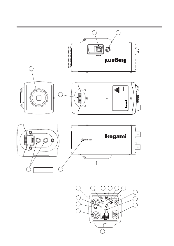
4. Names of parts and their functions
6
1
5
(LEFT VIEW)
A VIEW
2
879
-
REV.
ICD
COLOR CAMERA
MODEL
TYPE
SER.NO.
AC24V 60Hz 4.3W/DC12V 4.2W
IKEGAMI TSUSHINKI CO., LTD.
(TOP VIEW)
MADE IN JAPAN
(RIGHT VIEW)
34
A
(REAR VIEW)
13
7
GENLOCK IN
15
16
14
HIGH
VIDEO OUT
LL
POWER
75Ω
TERM
D/N
REMOTE/
12
U
D
ONOFF
128
FOCUS EZ
R
GND
SET UP
CLASS2
AC24V60Hz4.3W
〜
DC12V 4.2W
10
9
11
17
E
19
18
E-5

① Lens mount (CS mount)
This is used to mount the lens on the camera. Many types of CS mount lens
can be used.
② Lens flange back focus adjuster
To be used to adjust the lens flange back focal distance (distance between lens
mounting edge and image focal point), if the camera fails to come into focus
with the lens' focus ring, this can be used for re-adjustment of lens back focus
when replacing lens.
③ Back focus lock screw
To be used to fix the lens flange back after it has been adjusted.
④ Camera mounting screw holes
These holes are used to install and fix the camera on the camera mounting or
bracket. Those can be also applicable to normal use tripods which have a quarter
inch thread. This mount, with two mounting holes, can be re-positioned on either
the bottom or the top of the camera as required.
Note:
To use these holes to attach the camera on a tripod or other mount, make
sure you use suitable size mounting bolts as follows (1/4" -20UNC), they
should not be longer than 5.5 mm to avoid an un-stable installation.
⑤ Lens iris control selector switch
The switch has two positions, for a video controlled auto-iris lens or a DC autoiris lens.
⑥ Auto iris lens connector
Specifically used to connect the auto iris lens.
• For the video controlled type auto iris lens
Set the lens selector switch to VIDEO position.
– Connector cable leads –
1. Red (power)
4
2
Auto iris lens
2. Not used
3. White (video)
4. Black (shielded)
3
1
* Make proper isolation on the tip of the green wire to prevent a short-circuit.
E-6

• For the DC controlled type auto iris lens
Set the lens selector switch to DC position.
– Connector cable wires –
1. Damping coil (-)
4
2
2. Damping coil (+)
3. Driving coil (+)
4. Driving coil (-)
3
1
* Connect the wires as shown above.
Please refer also to the instructions of the lens to be used.
3
Auto iris lens
1
4
2
Connector pin assignment
⑦- ⑪ Camera setup function switches
Please refer to the Operation chapter.
⑫ Focus EZ function switch
With an auto iris lens being connected, this switch is used to support the focus
adjustment. Hold down the U button longer than 2 seconds, and the lens aperture
is kept open for about 1 minute. (Press it again, and the aperture opening time
will be prolonged for about 30 seconds.)
To end the Focus EZ function, just press the D button. This function helps
adjust the focus easily even in broad daylight no matter how much the depth of
field is. After using this button, the unit resets itself to its original focus mode.
⑬ External input connector (GENLOCK IN)
For Gen-lock input signal.
⑭ Video Output connector (VIDEO OUT)
For video signal output from camera. Connect this output to monitor or switcher,
etc. This to be terminated with 75 ohms impedance at the last equipment in a
loop when cascade/bridge loop connection is made.
E-7

⑮ Power indicator (POWER)
The LED indicator stays on in green while the camera power is on. This camera
does not have own power on/off switch. Utmost care should be paid when
doing repair or service work.
The maintenance indicator is built-in which makes blinking Amber and Green
lights around 40,000 hours operation. It is strongly recommended to have a
proper maintenance service if this maintenance indication LED blinks.
⑯ Terminal switch for GEN-LOCK
This is to terminate GEN-LOCK signal with 75 ohms impedance when the loop
connection is made in Gen-lock signal feed. To terminate, make this switch ON.
⑰ Terminal switch for RS-485
In RS-485 communication link , turn this switch to ON side for one-to-one control,
or turn it to OFF side for daisy-chain(loop connection).
(For use in daisy-chain connection, turn ON the terminal switch of the last device
in the link.)
⑱ RS-485 input/output vs. Day/Night change-over terminal block
This block is used for RS-485 connection or for remote control of day/nigh
switching.
⑲ DC12V/AC24V power input terminal
For power, apply the input power of DC10.5 - 28.0 V or AC24V ±10%.
* This installation should be made by a qualified service person and should
conform to all local codes.
E-8

5. Operation
5-1. User setup
The ICD-879 series camera has provision of camera setup and memory function
for camera ID setting, sync system selection, various picture quality setups for
optimum reproduction. Back light compensation spot area setting, Privacy Mask
settings, Day/Night change-over thresh-hold settings.
The SETUP MENU is shown in the system flow tree, and the settings can be easily
executed using the On-Screen-Menu system. Alteration of these functions may be
needed for some installations and we recommend that you should spend some
time to become acquainted with these functions so that the best results can be
obtained from this high performance TV camera.
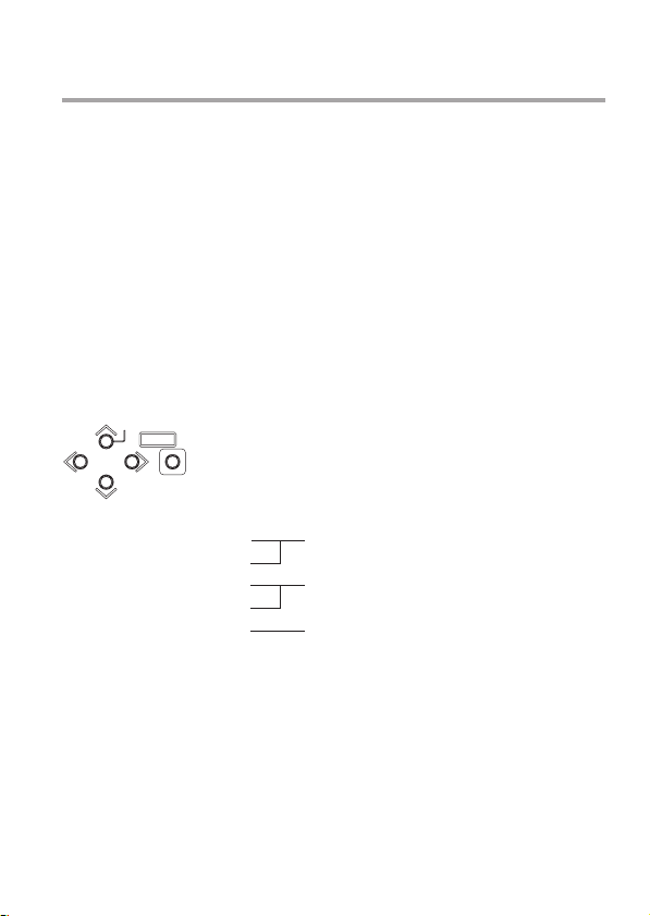
5-2. SETUP switches and functions
FOCUS EZ
SET UP
U
R
LL
D
Up Switch (U) To be used for a selection of SETUP parameters
Down Switch (D) (up and down).
Right Switch (R) To be used to change the settings.
Left Switch (L)
Enter Switch (E) To be used to enter or quit the setup mode and to
* To enter the setup mode, hold down the E button longer than 2 seconds.
The pushbuttons and the markings at left are provided on
the rear panel of the camera.
E
save the setup data.
E-9

5-3. Entering the setup mode and its basics
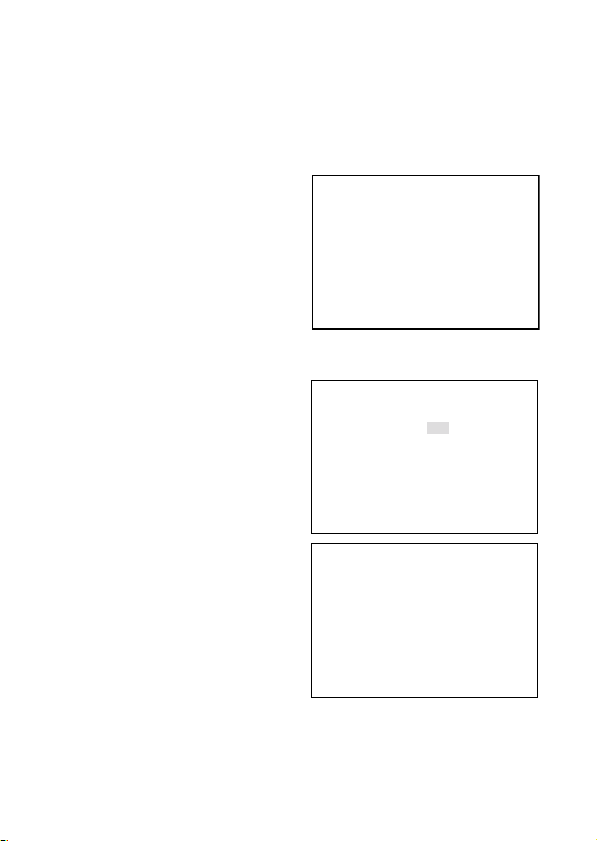
5-3-1. SETUP MENU (Main menu)
SETUP MENU
CAMERA ID OFF
SENS UP STD
SHUTTER X32 X32
LIGHT CONT. LENS
GAIN AGC
WHITE BAL. ATW1
SYNC INT
MENU LOCK OFF
EXIT CANCEL RESET
Hold down the E button longer than 2
seconds, and the menu at left appears
onscreen.
A highlighted item is now selected.
(1) CAMERA ID Up to 24 alpha-numeric characters can be displayed on
screen.
(2) SENS UP The electronic sensitivity up modes are selected.
The day (color) or night (Mono) mode is selected.
On or Off Selection of Flicker Free mode.
(3) SHUTTER To select high speed shutter, the electronic sensitivity
multiplying factor is also selected.
(4) LIGHT CONTROL The backlight compensation and sensing spot area
modes can be selected. The wide dynamic level and DC
type iris lens are adjusted.
(5) GAIN The gain control mode is selected.
(6) WHITE BALANCE The white balance mode is selected.
The manual white balance settings are made.
(7) SYNC The Sync systems, AC line Lock, internal Lock or Gen-
lock mode are selected.
(8) MENU LOCK The saved settings can be locked.
EXIT, CANCEL, RESET
(9)
The EXIT, CANCEL or RESET action is selected and
executed.
①EXIT: Used to save the settings and to quit the menu.
②CANCEL: Used to return the settings to the previously saved ones.
③RESET: Used to return the settings to the factory ones.
* New settings can be saved, if EXIT is selected to quit the menu.
E-10

5-3-2. SPECIAL MENU
SPECIAL MENU V1.00
PAGE 1/2
CHROMA L・・・・I・・・H
DETAIL L・・・・I・・・H
PEDESTAL L・・・・I・・・H
VIDEO LEV.L・・・・I・・・H
GAMMA 0.45
MATRIX A MODE
RET EXIT
(1) PAGE PAGE (1/2, 2/2) can be selected with the "L" and "R" buttons.
(2) CHROMA To be used to adjust the Chroma level.
(3) DETAIL To be used to adjust the details.
(4) PEDESTAL Pedestal level control.
(5) VIDEO LEV. To be used to adjust the video level.
(6) GAMMA To be used to select the gamma correction.
(7) MATRIX Selection of MATRIX Mode.
(8) MONITOR Selection of Monitor types, CRT or LCD types.
(9) P.MASK Privacy Mask control.
(10)MIRROR To be used to select mirror-reversed images.
(11)RS-485ID To be used to preset an ID number (1 to 207) for RS-485 link.
(12)LANGUAGE To select language of menu screen (either English or French).
(13)RET/EXIT RET for returning to the main menu screen.
EXIT for saving parameters or to quit the procedure.
Highlight EXIT on the SETUP MENU
screen. Hold down the L and R buttons
together, and the screen at left appears
on screen.
5-4. Setup procedures
5-4-1. CAMERA ID
(1) CAMERA ID ON/OFF setting
Highlight CAMERA ID. Using the E, L
or R button, access the ON/OFF setting.
Decide the ON or OFF setting with the
L or R button.
SETUP MENU
CAMERA ID OFF
SENS UP STD
SHUTTER X32 X32
LIGHT CONT. LENS
GAIN AGC
WHITE BAL. ATW1
SYNC INT
MENU LOCK OFF
EXIT CANCEL RESET
E-11


ID EDIT
ABCDEFGHIJKLMNOPQ
RSTUVWXYZ
↑ → ↓ ←
0123456789
:+−*/.・
・・・・・・・・・・・・・・・・
← →
SPACE CLEAR
RET EXIT POS
↑
↑
↑
↑
(2) ID characters setting
Keep CAMERA ID highlighted and press
the E button. The screen appears as
shown on the right figure.
① ID Setting for Line and Starting point:
For positioning the cursor, choose
arrow mark, ← or → , and push R or
L button.
② Choose desired characters, or
numbers, Use buttons of U, D, L, or
R to do it.
③ To use E button, to display the selected characters or numbers for ID.
④ To have a space, Select SPACE and push E button. the cursor moves.
⑤ To delete all ID characters and numbers, select CLEAR and push E button.
(3) Positioning of ID Display
ID display appears when push E button after choose POS. Move ID display to
the desired place and push E button. The ID position is set and the screen goes
back to normal screen.
(4) After this, decide to go back to the main menu (RET), or to save data and finish
this procedure (EXIT).
5-4-2. SENS UP
(1) This is to select the Electronic Sensitivity Increase function with L or R button.
The Gain mode will be AGC, while choosing Off, S/N or MOVE mode. It is
possible to change to HYP-AGC.
① OFF
Electronic Sensitivity Up function invalid.
② S/N
Signal to Noise priority Mode. It is recommended to shoot less or slow moving
object under lighting condition is varying.
③ STD (Factory Setting)
This is the Standard mode and this mode is recommendable under varying
lighting condition, but to have moderate TV reproduction in object blurr and
sreen noises as surface noises.
④ MOVE
This is the mode to have fast moving objects. The priority is on speed.
This may be used for the object such as cars on a street or in aparking lot
where objects are fast moving under varying light condition.
E-12
⑤ MANUAL
With this, Rate of Sensitivity Up is fixed with the shutter.
This may be favourably used under the stable lighting condition.
*Note: The same level of screen noise and blurr may be the same even in all three
mode of S/N, STD or MOVE, if the Sensitivity Up was set at its maximum
level.
(2) After selecting the preferable mode,
push E button. Then, the scrren as right
will appear and the setting for Day/Night
selection and On/Off selection of Flicker
Free mode.
* Flicker Free function does not work
when Sens.Up is set at OFF.
If you want to use Flicker Free function,
set 1/100 in SHUTTER setting mode.
SENS UP
DAY/NIGHT AUTO
FLICKER LESS OFF
RET EXIT
(3) DAY/NIGHT
With the L and R buttons, make the AUTO,
COLOR or B/W (Monochrome) setting.
① AUTO
Automatic switching is made: highquality color images during the day,
and high-sensitivity monochrome
pictures at night. Press the E button,
and the screen at right shows up.
• B/W BURST
The burst signal in Monochrome
(B/W) pictures can be selected ON
or OFF.
• SW LEVEL
The brightness level for switching
to the day or night mode can be
preset. With L and R button, the
levels can be selected in the order
of BRIGHT, MID and DARK.
DAY/NIGHT
B/W BURST ON
SW LEVEL MID
RET EXIT
DAY/NIGHT
B/W BURST OFF
SW LEVEL MANUAL
COL→B/W L・・・I・・・・H
X12
B/W→COL L・・・I・・・・H
X2
RET EXIT
The following screen appears, when selected MANUAL.
The thresh-hold can be set to change from color to monochrome picture,
or visa versa.
E-13

② REMOTE
SENS UP
DAY/NIGHT AUTO
FLICKER LESS OFF
RET EXIT
DAY/NIGHT
CONTROL SIGNAL MAKE
RET EXIT
The color or monochrome(B/W) mode
can be remotely selected by getting
the remote terminal at the back of the
camera open or short-circuited. In this
state, press the E button, and the submenu screen shows up. The terminal
polarity can now be preset.
• MAKE
The monochrome(B/W) mode can be selected by getting the remote
terminal short-circuited.
(The color mode can be selected with the terminal open.)
• BREAK
The monochrome(B/W) mode can be selected by getting the remote
terminal open.
(The color mode can be selected with the terminal short-circuited.)
③ COLOR
The color mode can be selected.
④ B/W
The Monochrome (B/W) mode can be selected. Press the E button in this
mode, and the menu opens up and the "B/W BURST" setting can be made
like as above ①.
(4) FLICKER LESS
① ON
To Make Flicker Free active while
Sensitivity Up is set.
The shutter speed is 1/100 a sec.,
when Sensitivity Up is OFF.
② OFF
The shutter speed is 1/60 a second,
when Sensitivity Up function is not
active.
5-4-3. SHUTTER
(1) This mode is effective, when the light control is LENS mode.
(2) When Sensitivity Up function is OFF (SENS UP = OFF)
① By L or R button, high speed shutter can be valid for OFF, FL (1/100), 1/125,
1/250, 1/500, 1/1000, 1/2000, 1/4000, 1/10,000, or Variable.
E-14

② VARIABLE
Speed of shutter can be changed
variably by L or R button, and the
shutter speed can be displayed on a
monitor screen. (When the setting
was so made)
(3)
When Sensitivity Up is ON (SENS UP = ON)
The electronic sensitivity multiplying
factor can be adjusted with the L and R
VARIABLE SHUTTER
SPEED L・・・・I・・・H
1/60
RET EXIT
buttons. x1, x2, x4, x6, x8, x12, x16, x24, x32
5-4-4 LIGHT CONTROL
(1) Select LIGHT CONTROL on the main menu using L or R button for AES or
LENS set. The Iris level can be displayed only when a lens change over switch
was on DC mode.
(2) BACKLIGHT CMP.
With this mode, the back light
compensation modes can be controlled
by L or R button. (for ON, SPOT, or OFF).
① OFF
The backlight compensation is not
active. This is the factory setting.
② SPOT
In this mode, the Spot measurement can
be made by setting the desired point.
③ ON
This mode is an ordinary back light compensation.
(3) BLC LEVEL
Move the marker by L or R button. Factory setting is at the middle.
The good result can be seen by moving marker to the right side, when the
difference of light amount was larger. It is recommended to control this by
watching the monitor screen.
(4) WIDE BLC
If the picture turned to white and make it difficult to observe, try this to have
better picture. This WIDE BLC makes compensation range larger to have
moderate brightness level make a picture comfortable to eyes.
(5) IRIS LEVEL
This is displayed when using DC Iris lens. Lens Iris moves to open by sliding
the marker to right. (Open means to make it brighter )
For this adjustment, it is recommended to do by watching a monitor screen.
LIGHT CONTROL
BACKLIGHT CMP. OFF
BLC LEVEL L・・・・I・・・H
WIDE BLC OFF
IRIS LEVEL L・・・・I・・・H
RET EXIT SPOT SET
E-15

↑
← RET →
↓
(6) RET/EXIT/SPOT SET
① RET
Returning to the main menu.
② EXIT
To save setup parameters and to quit.
③ SPOT SET
Displaying the screen of Spot area
setting, shown on the right.
1)↑: For the upper area control,
use this arrow and push E
button.
By using U or D button,
decide the area and return to
the light control mode by E
button.
2) ↓:To move the lower area setting mode by choosing this arrow and
push E button. By U or D button, decide the area and return to the
light control mode by E button.
3) ←:To select this for left side area setting mode. Using L or R button,
decide the area, then return to the light control mode by E button.
4) →: This arrow is for the control of the right side area. By L or R button,
decide the area, then return to the light control mode by E button.
5-4-5. GAIN
(1) By L or R button, the gain control modes can be selected.
① LOW
This fixed-gain mode keeps the sensitivity low for brighter spots.
This can be used for relatively comfortable picture reproduction with less
video noise. Normally it is used with ample light condition.
② MID
This fixed-gain mode keeps the sensitivity middle between HIGH and LOW.
③ HIGH
The fixed-gain mode keeps the sensitivity high for darker scene.
④ AGC
This mode is initially set to automatically optimize the sensitivity and noise
levels.
E-16

⑤ HYP-AGC
This mode is higher in sensitivity than normal AGC mode for very dark scene.
Then, sometimes pictures may look rugged and maybe with conspicuous
video noises, due to forced higher sensitivity to reproduce dark scene.
* When SENS UP function is either of those S/N, STD, MOVE, or when DAY/
NIGHT is set at AUTO, AGC or HYP-AGC only can be selected for AGC.
● Round Numbers of Brightness Expression
100000Lux
10000Lux
1000Lux
100Lux
10Lux
1Lux
0.1Lux
0.01Lux
0.001Lux
• Sun Light in clear cloudless sky (10000Lux)
• The sun Light after 1 hour from dawn in overcasting weather (2000Lux)
• Sun Light 1 hour before the Sun Set (1000Lux)
• Twilight (100Lux)
• Evening Dusk (1Lux)
• Full moon night (0.1Lux)
• Waxing Moon (0.01Lux)
• Star lit evening with clear sky and without moon (0.001Lux)
• Office Desk with Fluorescent Illumination (1000Lux)
• Bright Pachinko Parlour or Casino (1000Lux)
• Convenience Store (500Lux)
• Writing Desk (400Lux)
• Underground Station (300Lux)
• Underground Car Parking Lot (5~30Lux)
• Candle, 20 cm away (10~15Lux)
5-4-6. WHITE BALANCE
(1) By L or R button, The white balance mode can be selected.
① ATW-1 (Factory Set Position)
Automatically, white balance is controlled.
② ATW-2 :
In this mode, the white balance control is made. But this ATW-2 mode covers
wider range in the light spectral to cover the Sodium lighting.
May be not so accurate tracking as ATW-1 mode is expected, or sometimes
a small difference in color reproduction from ATW-1, may occur in this ATW-
2.
E-17

WHITE BALANCE
R GAIN L・・・・I・・・H
B GEIN L・・・・I・・・H
RET EXIT
③ AWC :
This is an ordinary one-push Automatic white balance control. Using white
object and E button, white balancing is set. In this mode, setting parameters
will not change by lighting variations. This mode is accurate compared with
other white balance setting modes and is recommended in a stable lighting
situation.
④ MANUAL :
By selecting MANUAL and push E
button, the screen shown on the right
will appear for the manual color
control.
R GAIN is for an adjustment of Red
color.
B GAIN is for an adjustment of Blue
color.
● Color Temperatures in Degrees Kelvin
Color Temperature is the standard method to
describe characters of light and is normally
expressed in degrees kelvin (K) Large
numbers show more blueish color.
(Not directly related Brightness)
2 hours from Dawn
1 hour from Dawn
Early Sunrise
Before and after Sunrise/Sunset
10000K
9000K
8000K
7000K
6000K
5000K
4000K
3000K
2000K
1000K
Clear Blue Sky
TV screen
Over cast sky
Sun Light
White Fluorescent Lamp
Halogen Lamp
Incandescent Lamp
Sodium Lamp
Candle Light
E-18

5-4-7 SYNC
(1) By L or R button, INT, LL, EXT VS or EXT VBS can be selected.
(2) INT = Internal Lock
This is for internal sync lock mode, controlled by internal crystal oscillator.
(3) LL = Line Lock
This is for AC line lock mode. In this AC
Line Lock mode, phase adjustment can
be possible. To do it, Press E button,
and the screen at right shows up for
coarse and fine phase adjustment.
① COARSE
It makes possible to have 90 degree
increment from 0°, 90°, 180° or 270°.
② FINE :
By L or R button, fine adjustment of the phase is possible.
(4) EXT VS
By pushing E button, the screen for
adjustment will appear and the H phase
adjustment can be done by L or R
button.
Note that this mode can be valid when
VS signal input with Gen-lock mode.
(5) EXT VBS
By pushing E button, the screen for
adjustment will appear and the following
parameters are becomes controllable.
① H PHASE
The horizontal phase can be
controlled by L or R button.
② SC COARSE
The sub-carrier phase can be
controlled by L or R button with 45
degrees steps.
③ SC FINE
After the above SC COASE adjustment, fine tuning of sub-carrier phase
can be controllable by L or R button.
SYNC LL
COARSE 0 DEG
FINE L・・・・I・・・H
RET EXIT
SYNC VS
H PHASE L・・・・I・・・H
RET EXIT
SYNC VBS
H PHASE L・・・・I・・・H
SC COARSE 0 DEG
SC FINE L・・・・I・・・H
RET EXIT
E-19

5-4-8. MENU LOCK
SPECIAL MENU V1.00
PAGE 1/2
CHROMA L・・・・I・・・H
DETAIL L・・・・I・・・H
PEDESTAL L・・・・I・・・H
VIDEO LEV.L・・・・I・・・H
GAMMA 0.45
MATRIX A MODE
RET EXIT
To prevent un-intentional or intentional setup parameter change, this Menu Lock
function is provided for protection. The menu lock function protects saved setting
parameters against accidental or intentional alteration.
(1) To Lock
To secure the saved setting parameters to make it ON, using L and R buttons.
(2) Operation
When locked, only EXIT is effective and all the other actions are invalid.
(3) Unlock
To un-lock, press U, R, D, L, U, D and E buttons in this order.
If a wrong button is pressed halfway, start all over again.
5-4-9. SPECIAL MENU
(1) To go to the Special Menu, push L and
R buttons together at the SET UP
position. The SPECIAL MENU screen
shows up, as shown on right.
(2) CHROMA
With the L and R buttons, the chroma
level can be adjusted.
Make the adjustment to your desired
level while watching a monitor screen.
(3) DETAIL
With the L and R buttons, the detail level can be adjusted.
Make the adjustment to your desired level while watching a monitor screen.
(4) PEDESTAL
With the L and R buttons, the pedestal level can be adjusted. Make this
adjustment to have your desired level while watching a monitor screen.
(5) VIDEO LEV.
With the L and R butons, the video level can be adjusted. Make the adjustment
to your desired level while watching a monitor screen.
(6) GAMMA
With the L and R buttons, the gamma correction can be selected (0.45/0.75/
1.0).
(7) MATRIX
Can select Matrix modes, A or B. In normal condition, the A mode is
recommendable, but special cases such as under florescent lighting, or in-door
situation, the B mode is possibly better for an optimum picture.
E-20

(8) MONITOR
By L or R button, picture reproduction mode of monitor can be selected.
① CRT
CRT is for Cathode Ray Tube(Blaun Tube) type monitors.
② LCD
LCD is for FDP, Flat Display Panel type monitors, such as LCD or Plasma.
(9) P.MASK
With E button, Privacy masking (P.Mask,
hereafter) control mode is available.
P.MASK can be set maximum 8 (eight)
points.
① Set to make it active (valid) or not.
By using U or D button, choose
desire Mask number/s, and make it
valid or invalid by L button for ON
(valid) or R button for OFF (invalid).
② Setting of Masking Area
The screen like the one on right
appears by E button after choosing
ON by L and R button.
1) Masking Area Size Change
Move a cursor by Arrow mark, and
use U or D button to move upper
or lower change. Or use L or R
button to move right or left
PRIVACY MASK
MASK1 OFF MASK5 OFF
MASK2 OFF MASK6 OFF
MASK3 OFF MASK7 OFF
MASK4 OFF MASK8 OFF
PAINT GRAY
RET EXIT
↑
← MOV →
↓
RET DEF DISP
change.
2) Masking Area reposition
Move a cursor to MOV and push E button. Whole mask can be repositioned
by buttons, U, D, R or L.
Push E button to set a position and return to P.MASK area set screen.
3) DEF
This is for controlling the mask size, or to initialize a position.
4) DISP
This shows the Mask which was set valid. DIPS stands for Display.
5) RET
To return to Mask Set Screen.
③ PAINT
With L or R button, desired color for P.Mask can be selected.
(Black, White or Gray)
E-21

④ RET
To return to the special menu screen.
⑤ EXIT
To save the selected parameters and to quit.
(10) MIRROR
With the L and R buttons, images can be mirror-reversed.
(11) RS-485 ID
Camera ID number can be set in 1 to 207 with R or L button.
(12) LANGUAGE
Language for the Menu screen can be selected, either English or French.
(13) RET
To return to the Main Menu.
(14) EXIT
To save the setup parameters, and to quit.
E-22
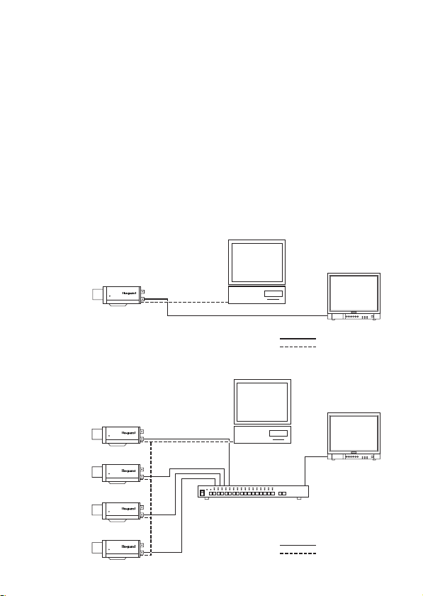
5-4-10. Communication with control device (RS-485)
The camera can be controlled from a control terminal (PC, for example) or the
remote control unit provided by Ikegami, over RS-485 Link.
The RS-485 is the recommended standard by EIA for a serial data communication,
one class higher than RS-422 which is for Multi-drop connection, but the 485 is the
Multi-points connection type. Maxim communication speed is 10Mbps and normally
extendable up to 1,200 meters.(3,600 ft).
When you make RS-485 connection, make it sure to connect the right terminal as
there are plus and minus polarity, and also make sure to terminate at the last
machine in the link of daisy chain.
For details, refer to the Communications Specifications.
Example 1: With one camera being connected
FOCUS LOCK
RS-485 Termination
switch ON
Example 2: With four cameras being connected
FOCUS LOCK
RS-485 Termination
switch OFF
FOCUS LOCK
RS-485 Termination
switch OFF
FOCUS LOCK
RS-485 Termination
switch OFF
FOCUS LOCK
RS-485 Termination
switch ON
E-23
PC
Legend
PC
Automatic switcher
Legend
Monitor
Coaxial cable
RS-485 control cable
Monitor
Coaxial cable
RS-485 control cable

6. Warranty and after-sale service
Warranty accompanies this product. Read and fill out the warranty card that you
have received at your dealer. Keep this card in a safe place.
● Please consult Ikegami Electronics (U.S.A.) Inc. or Ikegami Electronics (Europe)
GmbH or your dealer for full warranty information. Your dealer will repair or
replace free of charge within the warranty period according to the warranty
coverage.
● For repairs after the expiration of the warranty period, consult your dealer or
sales representative. It will first be judged whether the fault is repairable or not.
Charged servicing will then be made upon request of the user.
● Before you ask for servicing, please ensure you read the Instruction Manual. If
the unit still fails, take note of the model number, date of purchase, problem,
etc. in detail, and inform your dealer or sales representative.
● If you have questions about the after-sale service, contact your dealer or sales
representative.
*We suggest you ask for preventive inspection as soon as possible.
E-24

7. Specifications
(1) Image Sensor: 1/2-inch High Sensitive OCML IT CCD
(2) Pixel Number: Approx. 380,000 pixels,
(3) Scanning system: 525 TV lines, 59.94 Hz, 2 : 1 interlace in
(4) Sync system: INT/LINE-LOCK (phase adjustable) (Line-
(5) Video output: VBS 1.0 V p-p / 75 ohms
(6) Horizontal resolution: 540 TV lines in color. 570 lines in
(7) S/N ratio: More than 52d dB/rms
(8) Minimum object illumination: In color mode;
(9) Electronic sensitivity up: Up to 32 times
(10) AGC: ON (AGC, HYPER-AGC)/OFF (LOW, MID,
768(H) x 494 (V) (NTSC)
NTSC
lock not usable where the power frequency
and the camera's vertical frequency are
different from each other or when the
camera is DC-driven), Gen-lock or Crystal
controlled internal lock
monochrome mode. (in high-resolution
mode, at rated illumination)
(in normal mode, with AGC OFF, Detail
OFF )
0.11 lux at F1.2 (50 IRE, Hyper AGC, S-UP OFF)
0.15 lux at F1.4 (50 IRE, Hyper AGC, S-UP OFF)
0.0037 lux at F1.2 (50 IRE, Hyper AGC, S-UP ON)
0.005 lux at F1.4 (50 IRE, Hyper AGC, S-UP ON)
In Monochrome (B/W) mode;
0.022 lux at F1.2 (50 IRE, Hyper AGC, S-UP OFF)
0.03 lux at F1.4 (50 IRE, Hyper AGC, S-UP OFF)
0.011 lux at F1.2 (25 IRE, Hyper AGC, S-UP OFF)
0.015 lux at F1.4 (25 IRE, Hyper AGC, S-UP OFF)
0.00074 lux at F1.2 (50 IRE, Hyper AGC, S-UP ON)
0.001 lux at F1.4 (50 IRE, Hyper AGC, S-UP ON)
0.00037 lux at F1.2 (25 IRE, Hyper AGC, S-UP ON)
0.0005 lux at F1.4 (25 IRE, Hyper AGC, S-UP ON)
Automatic (S/N,STD,MOVE)/MANUAL
selectable
HIGH) selectable
E-25

(11) AES, Auto Electronic Shutter Built-in, On or Off selectable.
Control: 1 to 1600th max AES range
(12) White balance: AWC, ATW-1, ATW-2 and MANUAL
Selectable
(13) Gamma correction: 0.45, 0.75 or 1.0 switchable
(14) BLC, Built-in, On or Off selectable.
Back Light Compensation: Sensing Area Spot On or Off selectable.
(15) Optimum Monitor output Provided for CRT or LCD types, Selectable
selection:
(16) Day/night switching: Automatic/Remote/Manual selectable
(In the automatic mode, the day/night
switching level can be preset. In the remote
mode, the MAKE/BREAK setting can be
preset.)
(17) Auto iris function: Compatible with VIDEO iris and DC iris
(switchable, with DC iris level adjuster)
(18) Focus EZ function: Provided
(19) Camera ID: 1 Line
Up to 24 characters (alphanumeric and
symbols)
(20) Mirror function: Image mirror-reversal function ON/OFF
(21) Local setup: Selectable and adjustable with on-screen
display using pushbuttons on the camera
rear panel; Camera ID numbering, AGC
On/Off , Electronic sensitivity up ON/OFF,
Auto-White Balance ATW1&2, AWC, MANU
selection and adjustment, Sync Selection in
AC Line Lock, Internal Crystal controlled
Lock, LL phase adjustment, Adjustable
phase on external sync signal, iris level,
spot area setting, optimum monitor
selection for CRT or LCD types, Detail
correction management, Chroma level
control, Day/Night mode switching and
Thresh-hold
(22) Remote setup: Provided (Control by RCU-701/RCU-801 or
RS-485)
Same control parameters as with the local
setup on the rear panel
E-26

(23) Lens mount: CS mount
(24) Lens Flange Back Adjustment: Provided. Screw Lock type with rotary Disk
(25) Power Requirement: ① AC 24V ±10%, 60 Hz
or DC 12 V (+10.5V to +28 V)
② AC 100V, (Japanese version only)
(26) Power consumption/current: 4.3 watts nominal, 350mA, for AC 24V
4.2 watts nominal, 340mA, for DC 12V
4.0 watts nominal, for Japanese 100V
version
(27) Operating temperature -10°C to +50°C,
and relative humidity: +30 to +90% RH (No Condensation)
(28) Camera mount: 1/4" - 20UNC (top and bottom mountable)
(29) Outer dimensions: 62 (W) x 55 (H) x 122 (D) mm
(no protrusion included)
(30) Weight: 430g, AC 24 V and DC12 V version
(31) Input/output connectors: • VIDEO OUT; BNC
• GENLOCK IN; BNC
• LENS; 4P (E4-191J-150 type)
• DC 12V/AC 24V input; 2-pin terminal
block
• RS-485 input/output vs. Day/Night
change-over input; 5P push-in terminal
(32) Accessories: Instruction Manual, 1 copy
E-27

Muchas gracias por haber elegido esta cámara de TV de alta calidad de Ikegami.
Lea cuidadosamente este manual de instrucciones para mantener su cámara en
las mejores condiciones de funcionamiento durante el mayor tiempo posible. Todas
las cámaras de Ikegami han sido diseñadas y fabricadas con el máximo cuidado y
destreza para proporcionar una larga duración y un rendimiento de alta calidad,
siempre que sean utilizadas y mantenidas tal y como se explica en este manual.
Esta cámara de TV de alto rendimiento está equipada con un sensor CCD altamente
sensible de 1/2", el cual dispone de una amplísima gama de respuestas espectrales
que alcanzan casi hasta el espectro de infrarrojo próximo, y tiene muchas funciones
útiles para permitir un gran número de usos en muchas aplicaciones y condiciones
diferentes.
Este producto de Ikegami se fabrica con componentes que respetan el medio
ambiente, basándose en nuestra política corporativa y de responsabilidad social
que contribuye a la Solución Medioambiental Global para la conservación de la
energía y la sostenibilidad del medio ambiente. Ninguno de los componentes
utilizados en este producto es peligroso, tóxico o contiene plomo, y todos ellos
cumplen con los reglamentos de Productos Ecológicos de Japón(*), la directiva
RoHS de la UE y otros reglamentos y leyes relacionados con el Medio Ambiente y
Sustancias Químicas Peligrosas.
Contenido del manual de instrucciones de la ICD-879
1. Precauciones de manejo .............................................................. S-1
2. Generalidades .............................................................................. S-2
3. Características .............................................................................. S-3
4. Nombres de las partes y sus funciones ........................................ S-6
5. Funcionamiento ............................................................................ S-10
5-1. Configuración del usuario ..................................................... S-10
5-2. Conmutadores SETUP y sus funciones ................................ S-10
5-3. Entrada en el modo de configuración y sus puntos básicos . S-11
5-4. Procedimientos de configuración .......................................... S-12
6. Garantía y servicio postventa ....................................................... S-25
7. Especificaciones ........................................................................... S-26
8. External Appearance
9. Setup Menu Flow Chart
Pàgina

El signo de exclamación dentro de un triángulo equilátero tiene la finalidad de avisar al
usuario de la presencia de instrucciones de funcionamiento y mantenimiento
(reparaciones) importantes en los manuales que acompañan al aparato.
NOTA:
Este equipo ha sido probado y ha demostrado cumplir con los límites establecidos para
los dispositivos digitales de Clase B, de conformidad con el Apartado 15 de las Normas
de la FCC. Estos límites han sido diseñados para proporcionar una protección razonable
contra las interferencias perjudiciales en una instalación residencial. Este equipo genera,
utiliza y puede radiar energía radioeléctrica, y, si no se instala y utiliza según las
instrucciones, puede causar interferencias perjudiciales en las comunicaciones por radio.
Sin embargo, no existen garantías de que las interferencias no se produzcan en una
instalación particular. Si este equipo causa interferencias perjudiciales en la recepción de
emisiones de radio o televisión, lo que se puede determinar fácilmente apagando y
encendiendo el equipo, al usuario se le recomienda eliminar la interferencia tomando una,
o más, de las medidas siguientes.
AVISO:
CUALQUIER CAMBIO O MODIFICACIÓN NO APROBADA EXPRESAMENTE POR LA
PARTE RESPONSABLE DEL BUEN FUNCIONAMIENTO DEL APARATO PODRÍA
ANULAR LA AUTORIZACIÓN DEL USUARIO PARA UTILIZAR EL EQUIPO.
Instrucciones para eliminar equipos eléctricos y electrónicos de una casa
privada
Eliminación de equipos eléctricos y electrónicos usados
(Normas aplicables en la Unión Europea y en otros países europeos con
diferentes sistemas de recogida)
Este símbolo en el producto, o en los documentos relacionados, indica que este
producto no deberá ser tratado como un residuo doméstico normal. En cambio, deberá
ser llevado a un punto o lugar donde los equipos eléctricos y electrónicos sean
Asegurándose de que este producto sea eliminado correctamente, usted ayudará a impedir las
posibles consecuencias negativas sobre el medio ambiente y la salud humana que podrían ser
causadas por el manejo inapropiado de este producto. El reciclado correcto de los materiales
ayudará a conservar los recursos naturales.
Para conocer una información más detallada acerca del reciclado de este producto, póngase en
contacto con las autoridades de su localidad, con su servicio de recogida de residuos domésticos o
con el comercio donde adquirió el producto.
recogidos para ser reciclados.

1. Precauciones de manejo
• No instale la cámara en un lugar donde se salpique agua o donde haya mucha
humedad.
• No utilice la cámara donde la temperatura ambiental sea inferior a -10°C o superior
a +50°C. Las imágenes y las piezas componentes podrían ser afectadas o la
cámara podría funcionar mal.
• No abra nunca la caja de la cámara porque en su interior hay componentes
eléctricos y electrónicos de precisión y podría producirse un accidente.
• No meta ningún objeto metálico ni otras sustancias extrañas a través de las
aberturas de ventilación porque podría producirse un incendio o usted podría
recibir una descarga eléctrica.
• Asegúrese de desconectar la alimentación antes de instalar o conectar la cámara.
• No instale la cámara en lugares expuestos al calor, vibraciones o golpes.
•Tenga cuidado para no dejar caer ni golpear con fuerza la cámara mientras la
transporta.
• No toque el sensor de imagen.
• No oriente directamente la cámara hacia el sol.
• Algunos tipos de objetivos pueden sufrir oscilaciones bajo condiciones de
iluminación adversas. En tales casos, vuelva a ajustar el objetivo según las
instrucciones del manual.
* Debido a las características del dispositivo de imagen digital, las imágenes pueden
aparecer alteradas cuando las temperaturas son altas. Esto no significa que la
cámara esté estropeada.
S-1

2. Generalidades
Esta cámara en color dispone de un sensor CCD de 1/2 de pulgada con
transferencia entre líneas, 38.000 píxeles, alto rendimiento y tecnología de
microobjetivo en chip. La cámara tiene también una sensibilidad muy alta y una
respuesta espectral amplia con alta resolución, y está equipada con la función
para día/noche verdadera, compensación inteligente de luz de fondo mediante la
cual usted puede lograr una compensación de luz de fondo apropiada, control de
iris automático, sistema de bloqueo de línea de CA ajustable en fase o sistema de
bloqueo de sincronización interna controlada por cristal, varios modos convenientes
para equilibrar automáticamente el balance del blanco, y selección de salida de
monitoreo óptima para obtener la calidad de visualización más apropiada para los
monitores de CRT o LCD. La configuración y el control de la cámara también se
pueden hacer localmente en el panel trasero de la cámara o a distancia mediante
el control de software remoto I-LAN(*) a través de un enlace RS-485, y estos
datos de configuración se guardan en la memoria no volátil incorporada. La cámara
resulta muy apropiada para trabajos de vigilancia general, empleándola
individualmente o en sistemas integrados de gran escala para gestionar la
información visual.
* I-LAN: Software de control de sistemas de vigilancia de seguridad de Ikegami
para RS-485.
Consulte la sección 5-4-10 para conocer más acerca del control remoto
y RS-485.
S-2

3. Características
(1) Reproducción de TV de sensibilidad muy alta
Esta cámara altamente sensible, con CCD de 1/2", y de alto rendimiento,
emplea un elemento que aumenta la sensibilidad de forma electrónica con
una función de control automático de sensibilidad que permite reproducir
imágenes en color bajo condiciones de iluminación de tan solo 0,005 luxes.
La función de aumento de sensibilidad electrónica incorporada incremente la
sensibilidad hasta 32 veces más. Además, también se provee una función de
día/noche verdadera que resulta muy útil para filmar objetos en movimiento
bajo condiciones de iluminación baja sin ningún tipo de retardo.
(2) Función de cambio para día/noche
De día o cuando los objetos reflejan mucha luz se pueden capturar imágenes
en color de alta calidad. Cuando disminuye la luz o los objetos sólo reflejan
una luz mínima, el sistema del filtro IR móvil incorporado se activa para
proporcionar imágenes en blanco y negro debido a una sensibilidad más alta.
Esta fiable función de cambio para día/noche verdadera proporciona una
imagen en blanco y negro de alta resolución de 570 líneas de TV incluso bajo
condiciones de muy poca luz, con iluminación de escenas mínima de 0,015
luxes.
El umbral de cambio se puede establecer manualmente o preestablecerse
para la operación automática desde el control del panel trasero de la cámara
o a distancia mediante el software remoto I-LAN a través de un enlace RS-
485. Este sistema de cambio para día/noche permite obtener imágenes sin
retraso e imágenes que no son falsas durante todo el día y la noche.
La cámara también se puede enlazar con sensores externos y realizar una
operación de sistema de alarma efectivo.
(3) Imagen de alta calidad y alta resolución
La cámara ha sido diseñada para que haga poco ruido y que la imagen no
tenga borrosidad. El DSP (procesador de señal digital) mejora eficazmente
los detalles, con lo que se logra una imagen nítida con una relación de señal
a ruido alta. El alto rendimiento proporciona una resolución horizontal de 540
líneas de TV para colores, y de 570 líneas de TV para blanco y negro.
S-3

(4) Alto rendimiento, alta sensibilidad y baja borrosidad vertical
El CCD de transferencia entre líneas más reciente, con tecnología de
microobjetivo en chip, proporciona una respuesta espectral más amplia desde
el infrarrojo próximo visible a invisible, para reproducir de forma efectiva
imágenes de alta calidad tomadas en lugares poco iluminados. Y el DSP
(procesador de señal digital) mejorado permite obtener una buena relación
señal a ruido de 52 dB con un buen rendimiento de la protección contra la
sobrecarga de píxeles verticales de -126 dB conocida como borrosidad vertical
que se produce con fuentes de luz muy intensa.
(5) Compensación inteligente de la luz de fondo
La bien diseñada BLC (compensación de luz de fondo) puede asignar una
zona de compensación de luz de fondo para obtener una reproducción de
imágenes claras y equilibradas, empleando para ello los conmutadores del
panel de control trasero o a distancia mediante enlace.
(6) Control automático del iris de dos formas
Esta función se encuentra disponible para poder cambiar entre el objetivo con
iris tipo vídeo y el objetivo con iris tipo DC. Es decir, se puede utilizar la mayoría
de los objetivos con iris automático para CCTV.
(7) Balance automático del blanco
Gracias al control del balance del blanco de seguimiento automático (ATW),
el balance del blanco se ajusta automáticamente sin importar lo grande que
sean las fluctuaciones en la temperatura del color del motivo. La ICD-879
proporciona varias funciones útiles para realizar el balance del blanco que
satisface los requerimientos más exigentes de los usuarios, lo que supone un
balance automático de los colores a tiempo completo, un balance de gama de
espectros ampliada (ATW-1 y ATW-2), un balance del blanco normal con un
solo toque y un balance manual para los controles de ganancia R y B
individuales.
(8) AES (Obturador electrónico automático)
Para asegurar una reproducción de imagen óptima constante se emplea un
control suave para compensar las variaciones de sensibilidad con un obturador
automático controlado electrónicamente, lo que supone un margen de control
de 1.600 a 1. Esta función AES proporciona una capacidad de reproducción
aceptable, equivalente a un margen de control del iris de F1,4 a F50, incluso
con objetivos de iris fijo.
S-4

(9) Función de enmascaramiento privado
La ICD-879 está equipada con la función de enmascaramiento privado, la
cual tapa zonas sensibles de la pantalla que necesitan permanecer ocultas a
la vista. Con esta función de enmascaramiento, y empleando los conmutadores
de control del panel trasero o a distancia con el enlace RS-485, usted puede
asignar de forma precisa un máximo de 8 zonas con un tamaño mínimo de 8
píxeles cuadrados. La unidad de configuración y control a distancia RCU-801
puede realizar la misma función.
(10)Ajuste de la distancia focal de brida
Se puede hacer un ajuste fácil girando un mecanismo de disco giratorio y un
tornillo de bloqueo al que se puede acceder convenientemente desde el lado
izquierdo. Esto puede ser útil cuando se hacen cambios entre objetivos de
una sola distancia focal, objetivos de distancia focal variable, objetivos de
distancia focal larga u objetivos zoom.
(11)Función de salida óptima del monitor
Con esta función única se puede obtener la calidad de imagen óptima para
los monitores CRT o LCD. Algunas veces, los monitores de pantalla plana tipo
LCD (pantalla de cristal líquido) con función de proceso digital muestran unas
características de reproducción diferentes, y usted podrá elegir esta selección
de salida para reproducir las mejores imágenes en la pantalla del monitor.
(12)Función de configuración de cámara remota o local y memoria de parámetros
La cámara de la serie ICD-879 está equipada con una función de memoria y
configuración de cámara controlada por microchip. La configuración de la
cámara se puede hacer de forma fácil localmente, empleando los
conmutadores de control del panel trasero de la cámara y la OSD (visualización
en pantalla), o a distancia mediante el I-LAN, software de control de cámara
de Ikegami, a través de un enlace RS-485. Además, una unidad opcional de
control y configuración a distancia, como la RCU-801, puede ser utilizada
con este propósito a través de una conexión con cable de vídeo coaxial.
(13)Función Focus EZ (enfoque fácil)
La apertura del objetivo de iris automático se mantendrá abierta. Incluso a
plena luz del día, el enfoque se puede ajustar fácilmente sin importar para
nada cuál es la profundidad de campo.
S-5
4. Nombres de las partes y sus funciones
1
VISTA A
6
2
5
MADE IN JAPAN
879
-
REV.
ICD
COLOR CAMERA
MODEL
TYPE
SER.NO.
AC24V 60Hz 4.3W/DC12V 4.2W
IKEGAMI TSUSHINKI CO., LTD.
(VISTA DEL
LADO
IZQUIERDO)
(VISTA
SUPERIOR)
(VISTA DEL
LADO
DERECHO)
34
A
(VISTA DEL LADO TRASERO)
13
7
GENLOCK IN
15
16
14
HIGH
VIDEO OUT
LL
POWER
75Ω
TERM
D/N
REMOTE/
12
U
D
ONOFF
GND
128
FOCUS EZ
R
AC24V60Hz4.3W
SET UP
CLASS2
DC12V 4.2W
10
9
11
17
E
〜
19
S-6
18

① Montura del objetivo (Montura CS)
Ésta se utiliza para montar el objetivo en la cámara. Se pueden utilizar muchos
tipos de objetivos de monturas CS.
② Ajustador de distancia focal de brida del objetivo
Se utiliza para ajustar la distancia focal de brida del objetivo (distancia entre la
cara de montaje del objetivo y el plano focal). Si la cámara no enfoca con el
anillo de enfoque del objetivo, el ajustador podrá utilizarse para volver a ajustar
el enfoque cuando se cambie el objetivo.
③ Tornillo de bloqueo de distancia focal de brida
Se utiliza para fijar la distancia focal de brida del objetivo después de haberla
ajustado.
④ Agujeros para tornillos de montaje de la cámara
Estos tornillos se utilizan para instalar y fijar la cámara en la montura o ménsula
de la misma. También se pueden utilizar con trípodes de uso normal con roscado
de un cuarto de pulgada. Esta montura, con dos agujeros de montaje, se puede
posicionar en la parte superior o inferior de la cámara, según sea necesario.
Nota:
Para utilizar estos agujeros y colocar la cámara en un trípode u otra montura,
asegúrese de utilizar los pernos de montaje del tamaño adecuado (1/4"20UNC). Éstos no deberán tener más de 5.5 mm de longitud para evitar así
que la instalación sea inestable.
⑤ Conmutador selector del iris del objetivo
El conmutador tiene dos posiciones: una para objetivo de iris automático
controlado por vídeo y otra para objetivo de iris automático DC.
⑥ Conector de objetivo de iris automático
Se utiliza específicamente para conectar el objetivo de iris automático.
• Para el objetivo de iris automático del tipo controlado por vídeo
Ponga el conmutador selector del objetivo en la posición VIDEO.
– Conductores del cable del conector –
1. Rojo (alimentación)
4
2
Objetivo de
iris automático
2. No se utiliza
3. Blanco (vídeo)
4. Negro (blindado)
3
1
* Aísle correctamente la punta del cable verde para impedir un cortocircuito.
S-7

• Para el objetivo de iris automático del tipo controlado por DC
Ponga el conmutador selector del objetivo en la posición DC.
– Conductores del cable del conector –
1. Bobina de amortiguamiento (-)
4
2
2. Bobina de amortiguamiento (+)
3. Bobina de excitación (+)
4. Bobina de excitación (-)
3
1
* Conecte los cables como se muestra más arriba.
Consulte también las instrucciones del objetivo que va a utilizar.
3
Objetivo de iris
automático
1
4
2
Asignación de contactos del conector
⑦- ⑪ Conmutadores de funciones de configuración de la cámara
Consulte el capítulo Funcionamiento.
⑫ Conmutador de función Focus EZ (enfoque fácil)
Cuando se conecta un objetivo de iris automático, este conmutador sirve para
ayudar a ajustar el enfoque. Mantenga pulsado el botón U durante más de 2
segundos y la apertura del objetivo se mantendrá abierta durante 1 minuto
aproximadamente. (Púlselo de nuevo y el tiempo de apertura se prolongará
durante otros 30 segundos.)
Para finalizar la función Focus EZ, pulse simplemente el botón D. Esta función
ayuda a ajustar el enfoque fácilmente incluso a plena luz del día, sin importar
cuánta es la profundidad de campo. Después de utilizar este botón, la unidad
cambia automáticamente al modo de enfoque original.
⑬ Conector de entrada externa (GENLOCK IN)
Para la señal de entrada del sincronizador de señales de vídeo.
⑭ Conector de salida de vídeo (VIDEO OUT)
Para la salida de señales de vídeo de la cámara. Conecte esta salida al monitor,
conmutador, etc. Esto terminará con una impedancia de 75 ohmios en el último
equipo del bucle cuando se haga una conexión en bucle tipo cascada/puente.
S-8

⑮ Indicador de la alimentación (POWER)
El indicador LED permanece encendido en color verde mientras está conectada
la alimentación de la cámara. Esta cámara no tiene su propio interruptor de
conexión/desconexión de la alimentación. Cuando se hagan trabajos de
reparación o mantenimiento deberá tenerse el máximo cuidado.
El indicador de mantenimiento está incorporado, y parpadeará en color ámbar
y verde después de unas 40.000 horas de funcionamiento. Si este indicador
LED de mantenimiento parpadea, se recomienda encarecidamente realizar un
servicio de mantenimiento apropiado.
⑯ Conmutador de terminal para GEN-LOCK
Este conmutador sirve para terminar la señal GEN-LOCK con una impedancia
de 75 ohmios cuando la conexión de bucle se hace para la alimentación de
señales del sincronizador de señales de vídeo. Para terminar, ponga este
conmutador en ON.
⑰ Conmutador de terminación de conexión para RS-485
Conmutador de terminal para RS-485
En el enlace de comunicación RS-485, ponga este conmutador en ON para el
control uno a uno, o póngalo en OFF para la cadena de margarita (conexión en
bucle).
(Para usar en la conexión en cadena de margarita, ponga en ON el conmutador
del terminal del último dispositivo en el enlace.)
⑱ Bloque de terminales de entrada/salida de RS-485 en oposición al cambio
de día/noche
Este bloque se utiliza para la conexión de RS-485 o para el control remoto del
cambio día/noche.
⑲ Terminal de entrada de alimentación de DC12V/AC24V
Como suministro de alimentación de entrada aplique 10,5-28,0 V CC o 24 V
±10% CA.
* Esta instalación deberá realizarla un electricista cualificado y deberá cumplir
con todas las normas locales.
S-9
5. Funcionamiento
5-1. Configuración del usuario
La cámara de la serie ICD-879 dispone de función de configuración y memoria
para poner la identificación de la cámara, selección del sistema de sincronización,
varias configuraciones para que la calidad de la imagen de reproducción sea óptima,
configuración del área del punto de compensación de luz de fondo, configuración
de enmascaramiento privado y configuración de umbral de campo para día/noche.
El menú SETUP MENU se visualiza en un organigrama del sistema, y la
configuración se puede ejecutar fácilmente usando el sistema de menús que
aparecen en la pantalla. La alteración de estas funciones puede resultar necesaria
para algunas instalaciones, y nosotros recomendamos que usted se familiarice
con ellas para poder obtener los mejores resultados de esta cámara de TV de alto
rendimiento.
5-2. Conmutadores SETUP y sus funciones
FOCUS EZ
SET UP
U
R
LL
D
Conmutador de subida (U) Se utilizan para seleccionar los parámetros
Conmutador de bajada (D) SETUP (subida y bajada).
Conmutador derecho (R) Se utilizan para cambiar la configuración.
Conmutador izquierdo (L)
Conmutador de entrada (E) Se utiliza para entrar en el modo de
* Para entrar en el modo de configuración, mantenga pulsado el botón E durante
más de 2 segundos.
Los conmutadores y las marcas de la ilustración de la
izquierda se encuentran en el panel trasero de la cámara.
E
configuración o salir de él, y para guardar los
datos de la configuración.
S-10

5-3.
Entrada en el modo de configuración y sus puntos básicos
5-3-1. SETUP MENU (Menú principal)
SETUP MENU
CAMERA ID OFF
SENS UP STD
SHUTTER X32 X32
LIGHT CONT. LENS
GAIN AGC
WHITE BAL. ATW1
SYNC INT
MENU LOCK OFF
EXIT CANCEL RESET
(1) CAMERA ID
En la pantalla se pueden visualizar hasta 24 caracteres alfanuméricos.
(2) SENS UP
Se seleccionan los modos de aumento de sensibilidad electrónica.
Se selecciona el modo de día (color) o noche (blanco y negro).
Selección de activación o desactivación del modo sin parpadeo.
(3) SHUTTER
Al seleccionar el obturador de velocidad alta también se selecciona el factor de
multiplicación de sensibilidad.
(4) LIGHT CONTROL
Se pueden seleccionar los modos de compensación de luz de fondo y fotometría
de punto. El nivel de gama dinámica amplia y el objetivo de iris tipo DC se
ajustan.
(5) GAIN
Se pueden seleccionar los modos de control de ganancia.
(6) WHITE BALANCE
Se puede seleccionar el modo del balance del blanco. Y se puede hacer el
ajuste manual del balance del blanco.
(7) SYNC
Se pueden seleccionar los sistemas de sincronización, el modo de bloqueo de
línea de CA, el modo de bloqueo interno de señales de vídeo.
(8) MENU LOCK
La configuración guardada se puede bloquear.
(9) EXIT, CANCEL, RESET
La acción de EXIT, CANCEL o RESET se selecciona y se ejecuta.
①EXIT: Se utiliza para guardar la configuración y salir del menú.
②CANCEL: Se utiliza para cambiar la configuración por otra que fue guardada
previamente.
③RESET: Se utiliza para recuperar los ajustes de fábrica.
* La configuración nueva se puede guardar si se seleccionó EXIT para salir
del menú.
Mantenga pulsado el botón E durante
más de 2 segundos y el menú de la
izquierda aparecerá en la pantalla.
Ahora se selecciona un elemento
resaltado.
S-11

SETUP MENU
CAMERA ID OFF
SENS UP STD
SHUTTER X32 X32
LIGHT CONT. LENS
GAIN AGC
WHITE BAL. ATW1
SYNC INT
MENU LOCK OFF
EXIT CANCEL RESET
5-3-2. SPECIAL MENU (Menú especial)
SPECIAL MENU V1.00
PAGE 1/2
CHROMA L・・・・I・・・H
DETAIL L・・・・I・・・H
PEDESTAL L・・・・I・・・H
VIDEO LEV.L・・・・I・・・H
GAMMA 0.45
MATRIX A MODE
RET EXIT
(1) PAGE
Con los botones “L” y “R” se puede seleccionar PAGE (1/2, 2/2).
(2) CHROMA Se utiliza para ajustar el nivel de croma.
(3) DETAIL Se utiliza para ajustar los detalles.
(4) PEDESTAL Control de nivel de pedestal.
(5) VIDEO LEV. Se utiliza para ajustar el nivel de vídeo.
(6) GAMMA Se utiliza para seleccionar la corrección de gama.
(7) MATRIX Selección del modo MATRIX.
(8) MONITOR Selección de tipos de monitor. Tipos CRT o LCD.
(9) P.MASK Control de máscara privada.
(10)MIRROR Se utiliza para seleccionar las imágenes de espejo-invertidas.
(11)RS-485 ID Se usará para poner un número de identificación (1 a 207) para
el enlace RS-485.
(12)LANGUAGE Para seleccionar el idioma de la pantalla del menú (inglés o
francés).
(13)RET/EXIT RET para volver a la pantalla del menú principal.
EXIT para guardar los parámetros o abandonar el procedimiento.
Haga resaltar EXIT en la pantalla SETUP
MENU. Mantenga pulsados juntos los
botones L y R y aparecerá la pantalla de la
izquierda.
5-4. Procedimientos de configuración
5-4-1. CAMERA ID (Identificación de cámara)
(1) Ajuste de encendido/apagado para
CAMERA ID
Haga resaltar CAMERA ID. Utilizando
el botón E, L o R, acceda a la opción
ON/OFF. Elija la opción ON u OFF
con el botón L o R.
S-12

(2) Selección de caracteres de identificación
Mantenga resaltado CAMERA ID y
pulse el botón E. La pantalla aparece
como se muestra en la figura de la
derecha.
① Selección de identificación para
línea y punto de inicio
Para posicionar el cursor, elija las
marcas de flechas ← o → , y luego
pulse el botón R o L.
ID EDIT
ABCDEFGHIJKLMNOPQ
RSTUVWXYZ
0123456789
・・・・・・・・・・・・・・・・
← →
SPACE CLEAR
RET EXIT POS
↑
↑
↑
↑ → ↓ ←
:+−*/.・
↑
② Elija los caracteres o números deseados. Utilice los botones U, D, L o R
para hacer la elección.
③ Puede utilizar el botón E para visualizar los caracteres seleccionados o los
números para la identificación.
④ Para dejar un espacio, seleccione SPACE y pulse el botón E. El cursor se
mueve.
⑤ Para eliminar todos los caracteres y números de la identificación, seleccione
CLEAR y pulse el botón E.
(3) Posicionamiento de la visualización de la identificación
La visualización de la identificación aparece cuando se pulsa el botón E después
de elegir POS. Mueva la visualización de la identificación al lugar deseado y
pulse el botón E. La posición de la identificación se establece y la pantalla
pasa a ser la normal.
(4) Después de hacer esto, puede volver al menú principal (RET) o guardar los
datos y finalizar este procedimiento (EXIT).
5-4-2. SENS UP
(1) Éste es para seleccionar la función de aumento de sensibilidad electrónica con
el botón L o R. El modo de ganancia será AGC cuando se elija el modo OFF, S/
N o MOVE. Se puede cambiar a HYP-AGC.
① OFF
Función de aumento de sensibilidad electrónica no válido.
② S/N
Modo de prioridad de señal a ruido. Se recomienda para filmar motivos en
movimiento lento bajo condiciones de iluminación cambiantes.
③ STD (Ajuste de fábrica)
Éste es el modo estándar, y es el modo recomendado para condiciones de
iluminación cambiantes, pero la reproducción de las imágenes puede ser
de mala calidad, con borrosidad o ruidos en la pantalla.
S-13

DAY/NIGHT
B/W BURST ON
SW LEVEL MID
RET EXIT
④ MOVE
SENS UP
DAY/NIGHT AUTO
FLICKER LESS OFF
RET EXIT
Este modo es para objetos que se mueven rápidamente. La prioridad es la
velocidad. Este modo es muy apropiado para automóviles que circulan
rápidamente por las calles, o para estacionamientos, donde los vehículos
se mueven rápidamente bajo condiciones de iluminación cambiantes.
⑤ MANUAL
Con este modo, la velocidad de aumento de sensibilidad se fija con el
obturador. Esto se puede utilizar favorablemente bajo condiciones de
iluminación estable.
* Nota: Si el aumento de sensibilidad se ajusta el nivel máximo, el nivel de ruido
y borrosidad de la pantalla puede ser el mismo en los tres modos: S/N,
STD o MOVE.
(2) Después de seleccionar el modo
preferido, pulse el botón E. Luego
aparecerá la pantalla mostrada a la
derecha, con la selección para día/
noche y el encendido/apagado del
modo sin parpadeo.
* La función sin parpadeo no funciona
cuando el aumento de sensibilidad
está en OFF.
Si desea utilizar la función sin parpadeo, ponga 1/100 en el modo de ajuste
SHUTTER.
(3) DAY/NIGHT (Día/noche)
Seleccione AUTO, COLOR o B/W
(blanco y negro) con los botones L y R.
① AUTO
Se hace el cambio automático:
imágenes en color de alta calidad
durante el día e imágenes en
blanco y negro de alta sensibilidad
durante la noche. Pulse el botón E
y se mostrará la pantalla de la
derecha.
•B/W BURST
Se puede seleccionar ON u OFF para la señal de ráfaga de las
imágenes en blanco y negro (B/W).
S-14

• SW LEVEL
Se puede preajustar el nivel del
brillo para el cambio al modo de
día o al modo de noche. Con los
botones L y R, los niveles se
seleccionan en el orden de
BRIGHT, MID y DARK. Cuando se
selecciona MANUAL aparece la
pantalla siguiente. El umbral se
DAY/NIGHT
B/W BURST OFF
SW LEVEL MANUAL
COL→B/W L・・・I・・・・H
X12
B/W→COL L・・・I・・・・H
X2
RET EXIT
puede establecer para cambiar de imagen en color a imagen en blanco y
negro o viceversa.
② REMOTE
El modo de color o de blanco y negro
(B/W) se puede seleccionar a
distancia abriendo o cortocircuitando
el terminal de control remoto situado
en la parte posterior de la cámara.
En este estado, pulse el botón E y
aparecerá la pantalla de menú
DAY/NIGHT
CONTROL SIGNAL MAKE
RET EXIT
secundario. La polaridad del terminal se puede ajustar ahora.
• MAKE Cortocircuitando el terminal de control remoto se puede ajustar el
modo de blanco y negro (B/W). (Cuando se abre el terminal se
puede ajustar el modo de color.)
• BREAK Abriendo el terminal de control remoto se puede ajustar el modo
de blanco y negro (B/W). (Cuando se cortocircuita el terminal se
puede ajustar el modo de color.)
③ COLOR Se puede seleccionar el modo de color.
④ B/W Se puede seleccionar el modo de blanco y negro (B/W). Pulse el
botón E en este modo y el menú se abrirá, y la selección para “B/
W BURST” se podrá hacer como en el paso ① de más arriba.
(4) FLICKER LESS
① ON
Para activar la función sin parpadeo
mientras está establecido el
aumento de sensibilidad.
La velocidad del obturador es de 1/
100 de segundo cuando el aumento
de sensibilidad está en OFF.
② OFF
SENS UP
DAY/NIGHT AUTO
FLICKER LESS OFF
RET EXIT
La velocidad del obturador es de 1/60 cuando la función de aumento de
sensibilidad está desactivada.
S-15

5-4-3. SHUTTER (Obturador)
VARIABLE SHUTTER
SPEED L・・・・I・・・H
1/60
RET EXIT
LIGHT CONTROL
BACKLIGHT CMP. OFF
BLC LEVEL L・・・・I・・・H
WIDE BLC OFF
IRIS LEVEL L・・・・I・・・H
RET EXIT SPOT SET
(1) Este modo resulta eficaz cuando el control de luz está en el modo LENS.
(2) Cuando la función de aumento de sensibilidad está en OFF (SENS UP = OFF)
① Con el botón L o R se puede elegir entre las opciones OFF, FL (1/100),
1/125, 1/250, 1/500, 1/1000, 1/2000, 1/4000, 1/10.000 o Variable.
② VARIABLE
La velocidad del obturador se puede
cambiar de forma variable con el botón
L o R y se puede visualizar en la
pantalla del monitor. (Cuando se elija
la opción correspondiente para ello.)
(3) Cuando la función de aumento de
sensibilidad está en ON (SENS UP = ON)
El factor de multiplicación de
sensibilidad electrónica se puede ajustar con los botones L y R.
x1, x2, x4, x6, x8, x12, x16, x24, x32
5-4-4 LIGHT CONTROL (Control de luz)
(1) Con el botón L o R, seleccione LIGHT CONTROL en el menú principal para
AES o LENS. El nivel del iris sólo se puede visualizar cuando un conmutador
de cambio de objetivo está en el modo DC.
(2) BACKLIGHT CMP.
En este modo, el modo de compensación
de luz de fondo se puede controlar con el
botón L o R (para ON, SPOT u OFF).
① OFF
La compensación de luz de fondo no
está activada. Éste es un ajuste de
fábrica.
② SPOT
En este modo, la medición del punto
se puede hacer estableciendo el punto deseado.
③ ON
Este modo es para la compensación de luz de fondo habitual.
(3) BLC LEVEL
Mueva el marcador con el botón L o R. El ajuste de fábrica está en el punto
medio. El buen resultado se puede ver moviendo el marcador hacia el lado
derecho, cuando la diferencia de la intensidad de la luz es más grande. Se
recomienda controlar esto observando la pantalla del monitor.
S-16

(4) WIDE BLC
Si la imagen se pone blanca y resulta difícil verla, pruebe con este modo para
mejorarla. Este WIDE BLC amplia el margen de compensación para obtener
un nivel de brillo moderado y hacer que la imagen resulte confortable para los
ojos.
(5) IRIS LEVEL
Esto se visualiza cuando se utiliza un objetivo de iris DC. El iris del objetivo se
abre deslizando el marcador hacia la derecha. (Abrir en este caso significa
hacer más brillante.)
Se recomienda hacer este ajuste observando la pantalla del monitor.
(6) RET/EXIT/SPOT SET
① RET
Para volver al menú principal.
② EXIT (sortie)
Para guardar los parámetros de configuración y abandonar.
③ SPOT SET
Para visualizar la pantalla de ajuste
de la zona del punto mostrada a la
derecha.
1)↑: Para controlar el área
superior, utilice esta flecha
y pulse el botón E.
Utilizando el botón U o el
↑
← RET →
↓
botón D, elija la zona y
vuelva al modo de control
de luz mediante el botón E.
2) ↓: Para mover el modo de ajuste del área inferior eligiendo esta flecha
y pulsando el botón E. Con el botón U o el botón D, elija la zona y
vuelva al modo de control de luz mediante el botón E.
3) ←: Para seleccionar esto para el modo de ajuste de la zona del lado
izquierdo. Utilizando el botón L o el botón R, elija la zona y vuelva al
modo de control de luz mediante el botón E.
4) →: Esta flecha es para controlar la zona del lado derecho. Con el botón
L o el botón R, elija la zona y vuelva al modo de control de luz
mediante el botón E.
S-17

5-4-5. GAIN (Ganancia)
(1) Los modos de control de ganancia se pueden seleccionar con el botón L o R.
① LOW
Este modo de ganancia fija mantiene baja la sensibilidad para obtener puntos
más brillantes. Este modo se puede utilizar para reproducir imágenes
relativamente confortables con menos ruido de vídeo. Normalmente se utiliza
con condiciones de mucha luz.
② MID
Este modo de ganancia fija mantiene la sensibilidad media, entre HIGH y
LOW.
③ HIGH
Este modo de ganancia fija mantiene la sensibilidad alta para las escenas
oscuras.
④ AGC (commande de gain automatique)
Este modo se establece inicialmente para optimizar automáticamente la
sensibilidad y los niveles de ruido.
⑤ HYP-AGC (hyper-commande de gain automatique)
Este modo ofrece una sensibilidad más alta que el modo AGC normal para
escenas muy oscuras. Pero algunas veces, las imágenes pueden parecer
difusas y puede que tengan ruidos de vídeo debido a la sensibilidad más
alta forzada para reproducir escenas oscuras.
* Cuando la función SENS UP sea S/N, STD o MOVE, o cuando DAY/NIGHT
se ponga en AUTO, sólo AGC o HYP-AGC podrá seleccionarse para AGC.
● Números de luxes y brillo equivalente
100000 luxes
10000
1000
100
10
1
0.1
0.01
0.001
• Luz del sol en un cielo claro sin nubes (10000 luxes)
luxes
• Luz del sol 1 hora después de amanecer y con tiempo nublado (2000 luxes)
• Luz del sol 1 hora antes de la puesta del sol (1000 luxes)
luxes
luxes
• Al ponerse el sol (100 luxes)
luxes
luxes
• Anochecer (1 lux)
luxes
• Noche de luna llena (0,1 luxes)
luxes
• Luna creciente (0,01 luxes)
luxes
• Noche estrellada con cielo claro pero sin luna (0,001 lux)
• Escritorio de oficina con iluminación fluorescente (1000 luxes)
• Luz en el interior de una sala de juegos o un casino (1000 lux)
• Tienda de conveniencia (500 luxes)
• Escritorio (400 luxes)
• Estación del metro (300 luxes)
• Estacionamiento subterráneo de automóviles (5-30 luxes)
• Luz de vela, a 20 cm (10-15 luxes)
S-18

5-4-6. WHITE BALANCE (Balance del blanco)
(1) Con el botón L o R se puede seleccionar el modo de balance del blanco.
① ATW-1 (Posición de fábrica)
El balance del blanco se controla automáticamente.
② ATW-2
En comparación con el modo ATW-1, el modo ATW-2 cubre una gama más
amplia dentro del espectro óptico, incluyendo el que producen las lámparas
de sodio. El modo ATW-2 puede que no sea tan preciso, en lo que al
seguimiento se refiere, como el modo ATW-1. Algunas veces puede que
haya una pequeña diferencia en la reproducción del color entre los modos
ATW -1 y ATW-2.
③ AWC
Éste es el control automático habitual del balance del blanco que se realiza
mediante una sola pulsación. Utilizando un objeto blanco y el botón E se
puede establecer el balance del blanco. En este modo, los parámetros
preestablecidos no cambiarán debido a las variaciones de iluminación. Este
modo es más preciso si se compara con otros modos de balance del blanco,
y se recomienda para situaciones de iluminación estable.
④ MANUAL
Seleccionando MANUAL y pulsando
el botón E, la pantalla mostrada a la
derecha aparecerá para poder hacer
el control de color manual.
R GAIN es para ajustar el color rojo
B GAIN es para ajustar el color azul
● Temperaturas de color en grados Kelvin
La temperatura del color es un método
estándar que sirve para describir las
características de la luz y que se expresa
normalmente en grados kelvin (K). Los
números grandes indican un color más
azulado. (No está relacionada directamente
con el brillo.)
2 horas antes del amanecer
1 hora antes del amanecer
Salida del sol temprana
Antes y después de la salida/puesta del sol
WHITE BALANCE
R GAIN L・・・・I・・・H
B GEIN L・・・・I・・・H
RET EXIT
10000K
9000K
8000K
7000K
6000K
5000K
4000K
3000K
2000K
1000K
S-19
Cielo azul y claro
Pantalla de TV
Cielo nublado
Luz del sol
Lámpara fluorescente blanca
Lámpara halógena
Lámpara incandescente
Lámpara de sodio
Luz de vela

SYNC LL
COARSE 0 DEG
FINE L・・・・I・・・H
RET EXIT
5-4-7 SYNC (Sincronización)
SYNC VS
H PHASE L・・・・I・・・H
RET EXIT
SYNC VBS
H PHASE L・・・・I・・・H
SC COARSE 0 DEG
SC FINE L・・・・I・・・H
RET EXIT
(1) Con el botón L o R se puede seleccionar INT, LL, EXT VS o EXT VBS.
(2) INT = Bloqueo interno
Éste es el modo de bloqueo de sincronización interna controlado por un oscilador
de cristal interno.
(3) LL = Bloqueo de línea
Esto es para el modo de bloqueo de
línea de CA. En este modo de bloqueo
de línea de CA es posible hacer el ajuste
de fase. Para ello, pulse el botón E y
aparecerá la pantalla de la derecha para
hacer un ajuste de fase aproximado o
fino.
① COARSE
Los aumentos se pueden hacer en pasos de 90 grados: 0°, 90°, 180° o
270°.
② FINE
Con el botón L o R se puede hacer el ajuste fino de la fase.
(4) EXT VS
Pulsando el botón E aparecerá la pantalla
para hacer el ajuste, y el ajuste de fase
H se podrá hacer con el botón L o R.
Note que este modo podrá activarse
cuando se introduzca la señal VS con
el modo del sincronizador de señales
de vídeo.
(5) EXT VBS
Pulsando el botón E aparecerá la
pantalla para hacer el ajuste y podrán
controlarse los parámetros siguientes.
① H.PHASE
La fase horizontal se puede controlar
con el botón L o R.
② SC COARSE
La fase de subportadora se puede
controlar con el botón L o R en pasos
de 45 grados.
③ SC FINE
Después del ajuste de SC COARSE indicado anteriormente, el ajuste preciso
de la fase de subportadora se puede controlar con el botón L o R.
S-20

5-4-8. MENU LOCK (Bloqueo de menús)
Este menú de bloqueo se utiliza para impedir hacer cambios en los parámetros de
configuración, queriendo o sin querer. La función de bloqueo de menús protege
los parámetros establecidos y guardados para que no puedan ser alterados por
error o intencionadamente.
(1) Bloqueo
Para asegurar los parámetros establecidos y guardados elija ON con los botón
L y R.
(2) Operación
En el modo de bloqueo sólo sirve EXIT, y todas las demás acciones quedarán
invalidadas.
(3) Desbloqueo
Para desbloquear, pulse los botones U, R, D, L, U, D y E en este orden. Si se
pulsa algún botón equivocado, empiece de nuevo otra vez.
5-4-9. SPECIAL MENU (Menú especial)
(1) Para ir al menú especial, pulse L y R
juntos en la posición SET UP.
Aparecerá la pantalla SPECIAL MENU
de la derecha.
(2) CHROMA
El nivel de croma se puede ajustar con los
botones L y R. Haga los ajustes deseados
mientras observa la pantalla del monitor.
(3) DETAIL
Los detalles se pueden ajustar con los
botones L y R. Haga los ajustes de nivel deseados mientras observa la pantalla
del monitor.
(4) PEDESTAL
El nivel del pedestal se puede ajustar con los botones L y R. Haga el ajuste de
nivel deseado mientras observa la pantalla del monitor.
(5) VIDEO LEV.
Con los botones L y R se puede ajustar el nivel de vídeo. Haga el ajuste de
nivel deseado mientras observa la pantalla del monitor.
(6) GAMMA
Con los botones L y R se puede seleccionar la corrección de gamma (0,45/
0,75/1,0).
SPECIAL MENU V1.00
PAGE 1/2
CHROMA L・・・・I・・・H
DETAIL L・・・・I・・・H
PEDESTAL L・・・・I・・・H
VIDEO LEV.L・・・・I・・・H
GAMMA 0.45
MATRIX A MODE
RET EXIT
S-21
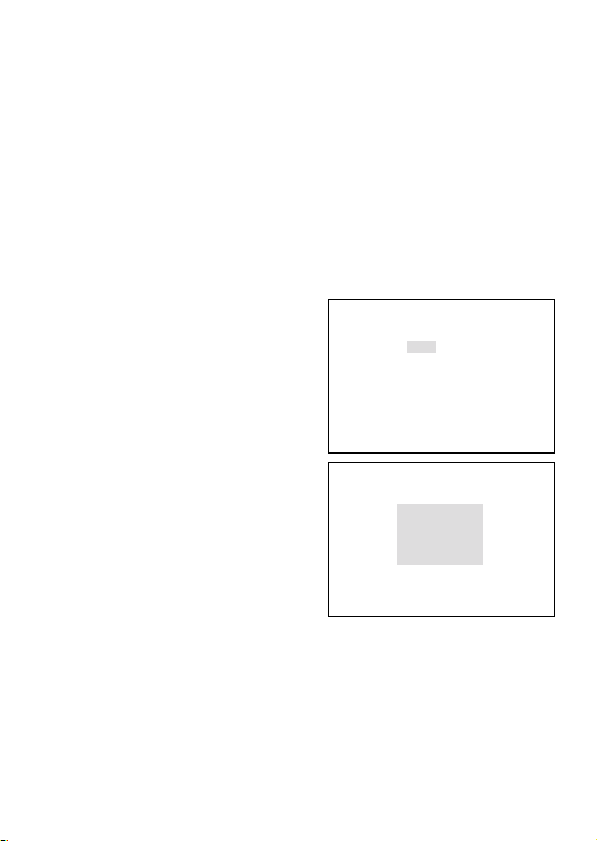
(7) MATRIX
↑
← MOV →
↓
RET DEF DISP
PRIVACY MASK
MASK1 OFF MASK5 OFF
MASK2 OFF MASK6 OFF
MASK3 OFF MASK7 OFF
MASK4 OFF MASK8 OFF
PAINT GRAY
RET EXIT
Seleccione el modo de matriz A o B. En condiciones normales se recomienda
el modo A, pero en casos especiales como, por ejemplo, bajo la luz de lámparas
fluorescentes o en interiores, el modo B resulta posiblemente mejor para obtener
unas imágenes óptimas.
(8) MONITOR
Con el botón L o R se puede seleccionar el modo de reproducción de imagen
del monitor.
① CRT
CRT es para los monitores de tubos de rayos catódicos (tubo Braun).
② LCD
LCD es para los monitores de pantalla plana (FDP) como, por ejemplo, las
pantallas LCD o las de plasma.
(9) P.MASK
Con el botón E se encuentra disponible
el modo de control de enmascaramiento
privado (a partir de ahora P.Mask).
P.MASK se puede establecer para un
máximo de 8 (ocho) puntos.
① Activación (válido) o desactivación.
Utilizando el botón U o D, elija el
número, o números, de
enmascaramiento deseado, y
actívelo o desactívelo con el botón
L para ON (activado) o con el
botón R para OFF (desactivado).
② Selección de la zona de
enmascaramiento
Después de elegir ON con los
botones L y R aparece una pantalla
como la de la derecha utilizando el
botón E.
1) Cambio de tamaño de la zona de enmascaramiento
Mueva el cursor mediante una marca de flecha y utilice el botón U o D
para desplazar la zona hacia arriba o hacia abajo. O utilice el botón L o R
para desplazarla hacia la derecha o hacia la izquierda.
2) Reposición de la zona de enmascaramiento
Mueva el cursor a MOV y pulse el botón E. Con el botón U, D, R o L se
podrá reposicionar toda la zona de enmascaramiento.
Pulse el botón E para establecer una posición y volver a la pantalla de
ajuste de la zona P.MASK.
S-22

3) DEF
Esto es para controlar el tamaño de la máscara o para inicializar una
posición.
4) DISP
Esto muestra la máscara que fue establecida como activada. DISP
significa pantalla.
5) RET
Para volver a la pantalla de ajuste de máscara.
③ PAINT
Con el botón L o R se puede seleccionar el color deseado para P.Mask.
(Negro, blanco o gris)
④ RET
Para volver a la pantalla del menú especial.
⑤ EXIT
Para guardar los parámetros seleccionados y abandonar.
(10) MIRROR
Con los botones L y R se pueden obtener imágenes de espejo-invertidas.
(11) RS-485 ID
Con el botón R o L se puede poner el número de identificación de la cámara,
que puede ser uno cualquiera de entre 1 a 207.
(12) LANGUAGE
Se puede seleccionar el idioma, inglés o francés, para la pantalla de menús.
(13) RET
Para volver a la pantalla del menú principal.
(14) EXIT
Para guardar los parámetros de configuración y abandonar.
S-23

5-4-10. Comunicación con dispositivo de control (RS-485)
La cámara puede ser controlada desde un terminal de control (un PC, por ejemplo)
o con la unidad de control remoto suministrada por Ikegami, a través del enlace
RS-485. RS-485 es la norma recomendada por la EIA para la comunicación de
datos en serie, una clase superior a RS-422 que es para la conexión entre más de
dos dispositivos, pero RS-485 es un tipo de conexión de múltiples puntos. La
velocidad máxima de comunicación es de 10 Mbps sobre una distancia de 1.200
metros (3.600 ft).
Cuando haga la conexión de RS-485, asegúrese de conectar los terminales
correctos, ya que hay polaridades positivas y negativas, y asegúrese también de
terminar en la última unidad que forma el enlace de cadena de margarita.
Para conocer detalles, consulte las Especificaciones de comunicación.
Ejemplo 1: Con una cámara conectada
FOCUS LOCK
Interruptor de terminación
RS-485 en ON
Ejemplo 2: Con cuatro cámaras conectadas
FOCUS LOCK
Interruptor de terminación
RS-485 en OFF
FOCUS LOCK
Interruptor de terminación
RS-485 en OFF
FOCUS LOCK
Interruptor de terminación
RS-485 en OFF
FOCUS LOCK
Interruptor de terminación
RS-485 en ON
S-24
PC
Leyenda
PC
Conmutador automático
Leyenda
Monitor
Cable coaxial
Cable de control de
RS-485
Monitor
Cable coaxial
Cable de control de
RS-485

6. Garantía y servicio postventa
Este producto va acompañado de una garantía. Lea y rellene la tarjeta de garantía
que usted ha recibido en el establecimiento de su concesionario y guárdela en un
lugar seguro.
● Consulte a Ikegami Electronics (U.S.A.) Inc., a Ikegami Electronics (Europe)
GmbH o a su concesionario para obtener una información completa de la
garantía. Su concesionario reparará o reemplazará el producto libre de todo
gasto siempre que no haya vencido el periodo de la garantía y se cumplan con
todas las condiciones de la misma.
● Para hacer reparaciones una vez que haya expirado el periodo de garantía,
consulte a su concesionario o representante de ventas. Éste juzgará primero si
el problema puede solucionarse o no. Los servicios que acarreen gastos serán
realizados una vez obtenido el consentimiento del usuario.
● Antes de solicitar el servicio de reparaciones, lea primero el manual de
instrucciones. Si la unidad sigue fallando, tome nota detallada del número del
modelo, la fecha de compra, el problema, etc. e informe a su concesionario o
representante de ventas.
● Si tiene alguna pregunta relacionada con el servicio postventa, no dude ponerse
en contacto con nuestro concesionario o representante de ventas.
* Le sugerimos que solicite una inspección preventiva con anticipación.
S-25

7. Especificaciones
(1) Sensor de imagen: CCD IT OCML de alta sensibilidad y 1/2 de
(2) Número de píxeles: 380.000 píxeles aproximadamente,
(3) Sistema de exploración: 525 líneas de TV, 60 Hz, entrelazado 2 : 1
(4) Sistema de sincronización: INT/LINE-LOCK (fase ajustable)
(5) Salida de vídeo: VBS 1,0 Vp-p/75 ohmios
(6) Resolución horizontal: 540 líneas de TV en color. 570 líneas en el
(7) Relación señal a ruido: Más de 52 dB/rms (en el modo normal, con
(8) Iluminación mínima del motivo: En el modo de color;
(9) Aumento de sensibilidad Hasta 32 veces
electrónica: Se puede seleccionar automático (S/N,
pulgada
768 (H) x 494 (V) (NTSC)
en NTSC
(El bloqueo de línea no se puede utilizar
donde la frecuencia de la alimentación y la
frecuencia vertical de la cámara son
diferentes entre sí o cuando la cámara se
acciona con CC), bloqueo interno
controlado por cristal o sincronizador de
señales de vídeo
modo de blanco y negro (en el modo de
alta resolución, con la iluminación
estándar)
AGC en OFF, Detail en OFF)
0,11 luxes a F1,2 (50 IRE, Hyper AGC, S-UP desactivado)
0,15 luxes a F1,4 (50 IRE, Hyper AGC, S-UP desactivado)
0,0037 luxes a F1,2 (50 IRE, Hyper AGC, S-UP activado)
0,005 luxes a F1,4 (50 IRE, Hyper AGC, S-UP activado)
En el modo de blanco y negro (B/W);
0,022 luxes a F1,2
0,03 luxes a F1,4
0,011 luxes a F1,2
0,015 luxes a F1,4
0,00074 luxes a F1,2
0,001 luxes a F1,4
0,00037 luxes a F1,2
0,0005 luxes a F1,4
(50 IRE, Hyper AGC, S-UP desactivado)
(50 IRE, Hyper AGC, S-UP desactivado)
(25 IRE, Hyper AGC, S-UP desactivado)
(25 IRE, Hyper AGC, S-UP desactivado)
(50 IRE, Hyper AGC, S-UP activado)
(50 IRE, Hyper AGC, S-UP activado)
(25 IRE, Hyper AGC, S-UP activado)
(25 IRE, Hyper AGC, S-UP activado)
STD, MOVE)/MANUAL
S-26

(10) AGC: ON (AGC, HYPER-AGC)/OFF (LOW, MID,
HIGH) seleccionable
(11) Control AES (obturador Incorporado, activado o desactivado
electrónico automático): seleccionable.
Margen AES de 1 a 1600 máximo
(12) Balance del blanco: AWC, ATW-1, ATW-2 y MANUAL seleccionable
(13) Corrección de gamma: 0,45, 0,75 o 1,0 conmutable
(14) BLC (compensación de luz Incorporado, activado o desactivado
de fondo): seleccionable. Punto de la zona de detección
activado o desactivado seleccionable.
(15) Selección de salida de Provista para los tipos CRT o LCD,
monitor óptima: seleccionable
(16) Cambio de día/noche: Automático/Remoto/Manual seleccionable
(En el modo automático se puede
preestablecer el cambio de día/noche. En
el modo de control remoto se puede
preestablecer el ajuste MAKE/BREAK.)
(17) Función de iris automático: Compatible con el iris VIDEO y el iris DC
(cambiable, con ajustador de nivel del iris DC)
(18)
Función Focus EZ (enfoque fácil)
: Provisto
(19) Identificación de la cámara: 1 línea
Hasta 24 caracteres (alfanuméricos y
símbolos)
(20) Función de espejo: Activación/desactivación de imagen de
espejo/invertida
(21) Ajuste local: Seleccionable y ajustable con la visualización
en pantalla utilizando pulsadores del panel
trasero de la cámara; numeración de
identificación de la cámara, AGC activado/
desactivado, ON/OFF para aumento de
sensibilidad electrónica, selección y ajuste del
balance automático del blanco (ATW-1/ATW-
2/AWC/MANU), selección de sincronización
en el bloqueo de línea de CA, bloqueo
controlado por cristal interno, ajuste de fase
LL, fase ajustable en la señal de sincronización
externa, nivel del iris, ajuste de la zona de
punto, selección óptima de monitor para los
tipos CRT y LCD, administración de corrección
detallada, control de nivel de croma, cambio
del modo de día/noche y umbral
S-27

(22) Ajuste remoto: Provisto (Control mediante RCU-701/RCU-
801 o RS-485)
Los mismos parámetros de control que con
la configuración local realizada en el panel
trasero
(23) Montura del objetivo: Montura CS
(24) Ajuste de distancia focal Provisto. Tipo de bloqueo por tornillo con
de brida: disco giratorio
(25) Alimentación: ① 24 V CA ±10%, 60 Hz, o 12 V CC
(+10,5 V a +28 V)
② 100 V CA (versión japonesa solamente)
(26) Consumo/corriente: 4,3 vatios nominal, 350 mA, para 24 V CA
4,2 vatios nominal, 340 mA, para 12 V CC
4,0 vatios nominal, para la versión
japonesa de 100 V
(27) Temperatura y humedad -10°C a +50°C, +30 a +90% de humedad
relativa de funcionamiento: relativa (sin condensación)
(28) Montura de la cámara: 1/4” - 20UNC (se puede montar en la parte
superior e inferior)
(29) Dimensiones exteriores: 62 (An) x 55 (Al) x 122 (Prof) mm (sin
incluir proyecciones)
(30) Peso: 430 g, versión de 24 V CA y 12 V CC
(31) Conectores de entrada/salida: • VIDEO OUT; BNC
• GENLOCK IN; BNC
• LENS; 4P (tipo E4-191J-150)
• Entrada de 12 V CC/24 V CA;
bloque de terminales de 2 contactos
• Entrada/salida de RS-485 en oposición a
la entrada de cambio de día/noche;
terminal de 5 contactos de conexión a
presión
(32) Accesorios: Manual de instrucciones, 1 copia
S-28
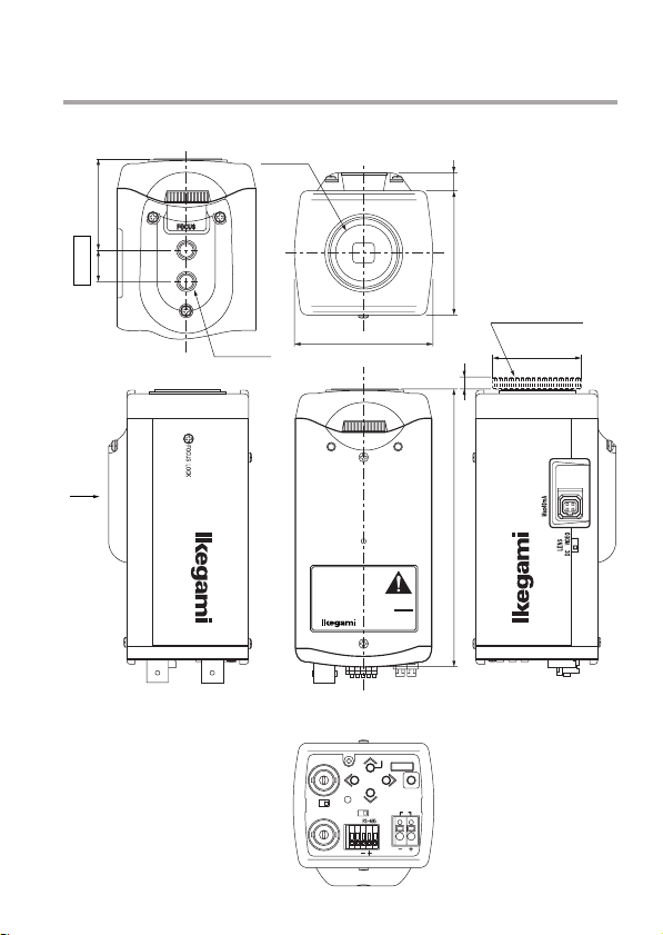
8. External Appearance
A VIEW
A
1"-32UN-2B
8
40 14
55
CMOUNTADAPTOR
2-1/4"-20UNC
62
(ACCESSORY)
ø30
5
122
COLOR CAMERA
MODEL
ICD-879
TYPE
REV.
AC24V 60Hz 4.3W/DC12V 4.2W
SER.NO.
IKEGAMI TSUSHINKI CO., LTD.
MADE IN JAPAN
FOCUS EZ
GENLOCK IN
HIGH
VIDEO OUT
SET UP
U
R
LL
D
D/N
REMOTE/
E
CLASS2
TERM
AC24V60Hz4.3W
ONOFF
〜
12
GND
DC12V 4.2W
POWER
75Ω
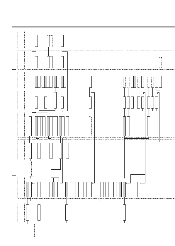
9. Setup Menu
TOP 3RD2ND
LR
U
D
LR
U
D
LR
U
D
LR
U
D
+E
EXIT
+E
RET
*ALPHANUMERIC
*POSITION
+E
ON
CAMERA ID OFF
+E
EXIT
+E
RET
+E +D
AUTO B/W BURST ON
OFFREMOTE
COLOR
SENS UP OFF DAY/NIGHT
DARK
MID
SW LEVEL
+E
B/W
*ADJUST
*ADJUST
B/W →COL
COL →B/W
BRIGHT
MANUAL
+E
AUTO
REMOTE
DAY/NIGHT
+E
S/N
MAKE
CONTROL SIGNAL
+E
COLOR
B/W
STD
MOVE
BREAK
FLICKER LESS OFF
MANUAL
+E
EXIT
+E
RET
+D
OFF
B/W BURST ON
+E
EXIT
ON
+E
RET
SENS UP = OFF
SHUTTER OFF
1/100
1/125
1/250
1/500
1/1000
1/2000
1/4000
1/10000
+E
EXIT
RET
+D
*ADJUST
+E
VARIABLE
+E
1/60~1/100000
SENS UP = S/N·STD·MOVE·MANUAL
x1x2x4x6x8
x12
x16
*Displayed by connecting DC controlled
Auto Iris Lens
*ADJUST
IRIS LEVEL
BACKLIGHT CMPOFF
+E
x24
x32
LIGHT CON. LENS
*Displayed by connecting DC controlled
*ADJUST
*ADJUST
OFF
BLC LEVEL
WIDE BLC ON
IRIS LEVEL
BACKLIGHT CMPON
+E
AES
Auto Iris Lens
+E
EXIT
+E
RET
*ADJUST AREA
*Displayed by connecting DC controlled
Auto Iris Lens
+E
EXIT+ESPOT SET
*ADJUST
*ADJUST
+E
RET
BLC LEVEL
IRIS LEVEL
SPOT
*Not available by connecting Auto iris lens
PUSHEFOR
AWHILE
SETUP MENU
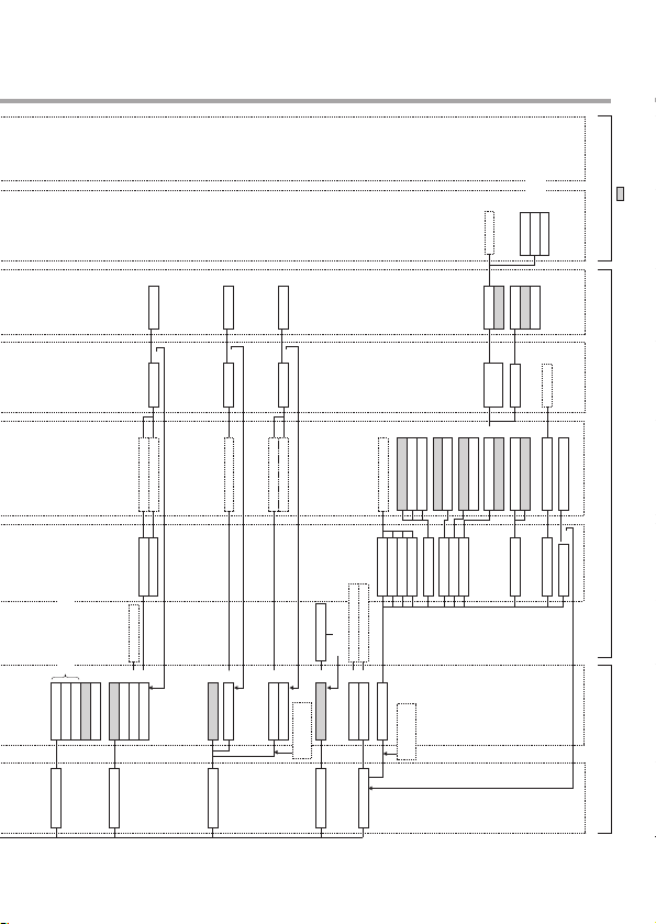
* FACTORY SETTING
Area, Position default set
Mask display
*ADJUST
AREA POSITION
RET
DEF
DISP
+E
+E
+E
Not available by set "AUTO" Mode for
DAY/NIGHT function
MID
HIGH
GAIN LOW
EXIT
+E
RET
*ADJUST
*ADJUST
R GAIN
B GAIN
*Tracking
+E
AGC
HYP-AGC
ATW1
ATW2
MANUAL+EAWC PUSH
WHITE BALANCE
SYNC INT
EXIT
+E
RET
*ADJUST
+E
LL
EXIT
+E
RET
SYNC VBS *ADJUST
SYNC VS *ADJUST
+E
+E
EXT VBS
EXT VS
+E
*Auto-Detection
Sync Signal
MENU LOCK OFF ON
+URDLUDE
*BEFORE SETTING
*DEFAULT
+E
CANCEL+ERESET
EXIT
0.75
0.45
*ADJUST
CHROMA
DETAIL
PEDESTAL
VIDEO LEV.
SPECIAL MENU
PUSH L AND R
AT ONCE
1.00
GAMMA
A MODE
B MODE
MATRIX
ON
OFF
WHITEPAINT
GRAY
BLACK
MASK1~
MASK8
*ADJUST
+E
LCD
CRT
ON
MONITOR
P. MASK
+E
OFF
001~207
EXIT
OFF
ON
*Initial value 001
+E
RS-485 ID
MIRROR
RET
TOP 3RD2ND

■ Ikegami Electronics (U.S.A.), Inc.
37 Brook Avenue, Maywood, N.J. 07607, U.S.A.
Phone: (201) 368-9171, FAX (201) 569-1626
www.Ikegami.com
or
■ Ikegami Electronics (U.S.A.), Inc, West Coast Office
2631 Manhattan Beach Blvd., Redondo Beach, C.A. 90278
Phone: (310) 297-1900, FAX (310) 536-9550
www.Ikegami.com
■ Ikegami Electronics (Europe) GmbH
Ikegami Strasse 1, D-41460 Neuss, Germany
Phone : 02131-123-0, FAX 02131-102820
www.Ikegami.de
■ Ikegami Electronics U.K. Office:
Unit E1, Cologne Court, Brooklands Close,
Windmill Road, Sunbury-on-Thames,
Middlesex, TW16 7EB, U.K.
Phone:01932-769700 FAX 01-92-769710
www.Ikegami.co.uk
Ikegami Tsushinki Co., Ltd.
Printed in Japan.
K40319
 Loading...