


IT-407

Dynamic Balance Tonearm Model: IT-407
Instruction Manual
1. Contents of the carton (Make sure the following contents are included in the carton)
① Arm assembly
② Counterbalance weight
③ Arm base
④ Headshell Contained in the printed
⑤ Wrench for tightening arm base fixing nuts (2 pcs) package
⑥ M2.6 screw (2 types)
⑦ Allen wrench
⑧ Template (used to determine the mounting position)
⑨ Shielded cable Inside upper cover of printed
⑩ Instruction manual (this booklet) package
2. Installation
(1) Locating the mounting position using the template
Use the template to locate the mounting position correctly, using caution not to allow
the counterbalance weight at the rear of the tonearm to come in contact with the
turntable cover. (Make sure the counterbalance weight does not come in contact with
the turntable cover when the cartridge mounted on the tonearm is positioned at the
center of the turntable.)
(2) Locking the arm base
Drill an arm base mounting hole 31 mm in diameter. Remove the nut and washer
from the arm base, and insert the base into the mounting hole in the turntable board,
and securely fasten it from the bottom of the board with the nut and washer. (Use the
arm base nut tightening wrench supplied with the tonearm.)
(3) Mounting the tone arm assembly on the arm base
Insert the arm assembly into the arm base mounted on the turntable board. Leave
the two arm base fixing screws a little loose. Adjust so that the turntable with a
record on it and the arm fitted with a cartridge (cartridge and rotating arm) are
parallel with each other, using the two fixing screws.
(4) Connecting the shielded cable to the arm assembly
Aligning the 5-pin connector guide with the notch inside of the arm shaft, plug the
- 1 -
5-pin connector of the shielded cable (output cable) into the arm shaft that sticks out
from the bottom of the turntable board, firmly all the way into the socket.
(5) Installing the cartridge to the headshell
The headshell comes attached with headshell lead wires (rhodium plated). Fit the
lead wire tips into the connector pins of the cartridge. The lead wires are color coded
according to the standard.
(R+: Red; R-: Green; L+: White; L-: Blue)
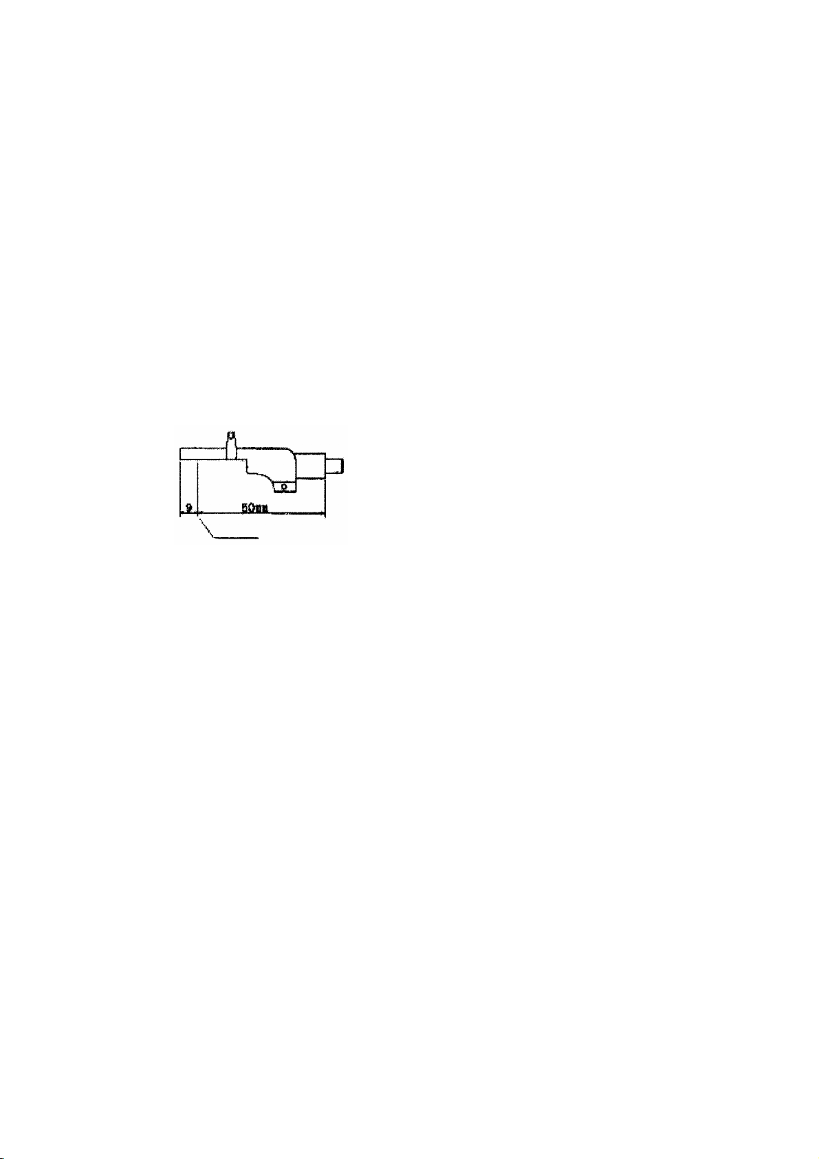
Adjust the headshell mounting position so that the stylus is positioned as shown in
Fig. 1.
[Fig. 1]
When the cartridge is adjusted as shown in
the figure, the effective length will be as
follows.
IT – 345 → 245 mm
Stylus position
IT – 407 → 307 mm
[Note]
Whenever replacing the cartridge with a new one due to a worn stylus, replace the
headshell lead wires as well with new ones. In order to get the most of the
performance of a 3-ohm low-impedance cartridge, it is important to keep the contacts
clean at all times to minimize the contact resistance. (Also keep clean other contacts
between the headshell leads and the shielded cable and between the matching
transformer and the head amplifier.)
(6) Adjusting tonearm fore-and-aft balance
Insert the headshell mounted with the cartridge into the 4-pin cylinder at the front
end of the arm assembly and secure it with the lock nut to ensure that the headshell
does not move. A loose headshell will result in the deterioration of sound quality.
At this time, leave the counterbalance weight fixing screw loosely tightened. Set the
stylus pressure gauge to “0”, and move the counterbalance weight back and forth to
adjust the arm balance, so that the balance tilts slightly towards the cartridge.
Tighten the counterbalance weight screw securely.
- 2 -
 Loading...