

Page 1

|KEA ®
30"(76.2CM) ISLAND-MOUNTCANOPY
RANGE HOOD
I ,_ i_¸ _,_I_ _
For questions about features, operation/performance, parts, accessories orservice, call: 1-866-664-2449.
In Canada,for assistance, installation and service, call: 1-866-664-2449.
CAMPANA DECOCINA PARAISLACON ESCUDETE
DE30"(76,2 CM)
Si tiene preguntas respecto alas caracteristicas, funcJonamJento,rendimJento,partes, accesorJoso servicio t@cnico,Ilameal: 1-866-664-2449.
HOTTEDECUISINIERECONFIGUREEENJLOT
30"(76,2CM)
Au Canada, pourassistance, installation ou service, composez le 1-866-664-2449
Table of Contents//ndice/Table des matieres .................................................................. 2
For warranty concerns, do not take the appliance back to the store. Please contact us in U.S.A. or Canada at 1-866-664-2449.
This product features a Limited Warranty - See the "Warranty" section for complete details. IKEA_ appliances carry a 5-year warranty
(excludes LAGAN family - see warranty for coverage details).
NOTE: Proof of Purchase is required to obtain warranty service.
Si tiene dudas acerca de la garantia, no devuelva el aparato a la tienda. Pongase en contacto con nosotros en los EE.UU. o en Canada
al 1-866-664-2449.
Este producto tiene una garantia limitada - Consulte la seccion "Garantia" para obtener todos los detalles. Los aparatos IKEA®tienen
una garantia de 5 a_os (excluyendo los de la familia LAGAN - consulte la garantia para ver los detalles acerca de la cobertura).
NOTA: Se requiere la prueba de compra para obtener servicio bajo la garantia.
Pour toute question concernant I'application de la garantie, ne pas rapporter I'appareil au magasin. Veuillez nous contacter aux €:.-U.
ou au Canada au 1-866-664-2449.
Ce produit est couvert par une garantie limitee -Voir lasection "Garantie" pour des details complets. Les appareils IKEA_ sont couverts
par une garantie de 5 ans (hormis les appareils de la serie LAGAN - voir la garantie pour des details concernant les modalites de
garantie).
REMARQUE : Une preuve d'achat est obligatoire pour obtenir I'application de la garantie.
iMPORTANT: READ AND SAVETHESE INSTRUCTIONS.
FOR RESIDENTIAL USE ONLY.
JMPORTANTE: LEA Y GUARDE ESTAS JNSTRUCCJONES.
SOLO PARA USO RESIDENClAL.
iMPORTANT : URE ET CONSERVER CES iNSTRUCTiONS.
POUR UTlUSATJON RESJDENTJELLE UNJQUEMENT.
LI302D/W10502581 D
Page 2

TABLEOF CONTENTS
RANGE HOOD SAFETY ................................................................. 3
INSTALLATION REQUIREMENTS ................................................ 4
Tools and Parts ............................................................................ 4
Location Requirements ................................................................ 5
Venting Requirements .................................................................. 6
Electrical Requirements ............................................................... 7
INSTALLATION INSTRUCTIONS .................................................. 7
Prepare Location .......................................................................... 7
Assemble Range Hood ................................................................ 8
Install Range Hood ....................................................................... 8
Make Electrical Connection ......................................................... 9
Install Duct Covers ..................................................................... 10
Complete Installation ................................................................. 10
[NDICE
SEGURIDAD DE LA CAMPANA PARA COCINA ....................... 17
REQUlSITOS DE INSTALACION ................................................. 19
Herramientas y piezas ................................................................ 19
Requisitos de ubicacion ............................................................. 19
Requisitos de ventilacion ........................................................... 20
Requisitos electricos .................................................................. 21
INSTRUCCIONES DE INSTALACION ......................................... 22
Prepare la ubicacion .................................................................. 22
Ensamble la campana para estufa ............................................ 23
Instalacion de la campana para cocina ..................................... 24
Conexion del suministro electrico .............................................. 24
Instalacion de las cubiertas de los ductos ................................ 25
Complete la instalacion .............................................................. 26
RANGE HOOD USE ...................................................................... 11
Range Hood Controls ................................................................. 11
RANGE HOOD CARE ................................................................... 12
Cleaning ...................................................................................... 12
WIRING DIAGRAM ...................................................................... 13
ASSISTANCE OR SERVICE ......................................................... 14
In the U.S.A................................................................................ 14
In Canada ................................................................................... 14
Accessories ................................................................................ 14
WARRANTY .................................................................................. 15
USO DE LA CAMPANA PARA COCINA ..................................... 26
Controles de la campana para cocina ....................................... 26
CUlDADO DE LA CAMPANA PARA COCINA ............................ 27
Limpieza ..................................................................................... 27
DIAGRAMA DE CABLEADO ....................................................... 28
AYUDA O SERVICIO TI_CNICO ................................................... 29
En los EE.UU .............................................................................. 29
Accesorios .................................................................................. 29
GARANTiA ..................................................................................... 30
TABLEDESMATIERES
SI_CURITI_ DE LA Ho'n'E DE CUlSINIi=RE ............................... 32
EXIGENCES D'INSTALLATION ................................................... 34
Outils et pieces ........................................................................... 34
Exigences d'emplacement ......................................................... 34
Exigences concernant I'evacuation ........................................... 35
Specifications electriques .......................................................... 36
INSTRUCTIONS D'INSTALLATION ............................................ 37
Preparation de I'emplacement ................................................... 37
Assemblage de la hotte ............................................................. 38
Installation de la hotte ................................................................ 39
Raccordement electrique ........................................................... 40
Installation des cache-conduits ................................................. 41
Achever I'installation .................................................................. 41
UTILISATION DE LA HOTTE ....................................................... 42
Commandes de la hotte de cuisiniere ....................................... 42
ENTRETIEN DE LA Ho'n'E .......................................................... 42
Nettoyage ................................................................................... 42
SCHI_MA DE C.&,BLAGE............................................................... 44
ASSISTANCE OU SERVICE ......................................................... 45
Au Canada .................................................................................. 45
Accessoires ................................................................................ 45
GARANTIE ..................................................................................... 46
2
Page 3

RANGE HOOD SAFETY
Your safety and the safety of others are very important.
We have provided many important safety messages in this manual and on your appliance. Always read and obey all safety
messages.
This is the safety alert symbol.
This symbol alerts you to potential hazards that can kill or hurt you and others.
All safety messages will follow the safety alert symbol and either the word "DANGER" or "WARNING."
These words mean:
You can be killed or seriously injured if you don't immediately
follow instructions.
You can be killed or seriously injured if you don't follow
instructions.
All safety messages will tell you what the potential hazard is, tell you how to reduce the chance of injury, and tell you what can
happen if the instructions are not followed.
Page 4
iMPORTANT SAFETY iNSTRUCTiONS
WARNING: TO REDUCE THE RISK OF FIRE, ELECTRIC
SHOCK, OR INJURY TO PERSONS, OBSERVE THE
FOLLOWING:
m Use this unit only in the manner intended by the
manufacturer. Ifyou have questions, contact the
manufacturer.
m Before servicing or cleaning the unit, switch power off at
service panel and lock the service disconnecting means to
prevent power from being switched on accidentally. When
the service disconnecting means cannot be locked,
securely fasten a prominent warning device, such as a tag,
to the service panel.
m Installation work and electrical wiring must be done by
qualified person(s) in accordance with all applicable codes
and standards, including fire-rated construction.
m Do not operate any fan with a damaged cord or plug.
Discard fan or return to an authorized service facility for
examination and/or repair.
m Sufficient air is needed for proper combustion and
exhausting of gases through the flue (chimney) of fuel
burning equipment to prevent backdrafting. Follow the
heating equipment manufacturer's guideline and safety
standards such as those published by the National Fire
Protection Association (NFPA), the American Society for
Heating, Refrigeration and Air Conditioning Engineers
(ASHRAE), and the local code authorities.
m When cutting or drilling into wall or ceiling; do not damage
electrical wiring and other utilities.
m Ducted fans must always be vented outdoors.
CAUTION: For general ventilating use only. Do not use
to exhaust hazardous or explosive materials and vapors.
CAUTION: To reduce risk of fire and to properly exhaust
air, be sure to duct air outside - do not vent exhaust air into
spaces within walls or ceilings, attics or into crawl spaces,
or garages.
WARNING: TO REDUCE THE RISK OF FIRE, USE ONLY
METAL DUCTWORK.
WARNING: TO REDUCE THE RISK OF A RANGE TOP
GREASE FIRE:
m Never leave surface units unattended at high settings.
Boilovers cause smoking and greasy spillovers that may
ignite. Heat oils slowly on low or medium settings.
m Always turn hood ON when cooking at high heat or when
flambeing food (i.e. Crepes Suzette, Cherries Jubilee,
Peppercorn Beef Flamb6).
m Clean ventilating fans frequently. Grease should not be
allowed to accumulate on fan or filter.
m Use proper pan size. Always use cookware appropriate for
the size of the surface element.
WARNING: TO REDUCE THE RISK OF INJURY TO
PERSONS IN THE EVENT OF A RANGE TOP GREASE
FIRE, OBSERVE THE FOLLOWING: a
m SMOTHER FLAMES with a close fitting lid, cookie sheet, or
metal tray, then turn off the burner. BE CAREFUL TO
PREVENT BURNS. Ifthe flames do not go out
immediately, EVACUATE AND CALL THE FIRE
DEPARTMENT.
m NEVER PICK UP A FLAMING PAN - you may be burned.
m DO NOT USE WATER, including wet dishcloths or towels -
a violent steam explosion will result.
m Use an extinguisher ONLY if:
- You know you have a class ABC extinguisher, and you
already know how to operate it.
- The fire is small and contained in the area where it
started.
- The fire department is being called.
- You can fight the fire with your back to an exit.
aBased on "Kitchen Fire Safety Tips" published by NFPA.
m WARNING: To reduce the risk of fire or electrical shock,
do not use this fan with any solid-state speed control
device.
READ AND SAVE THESE INSTRUCTIONS
INSTALLATIONREQUIREMENTS
b
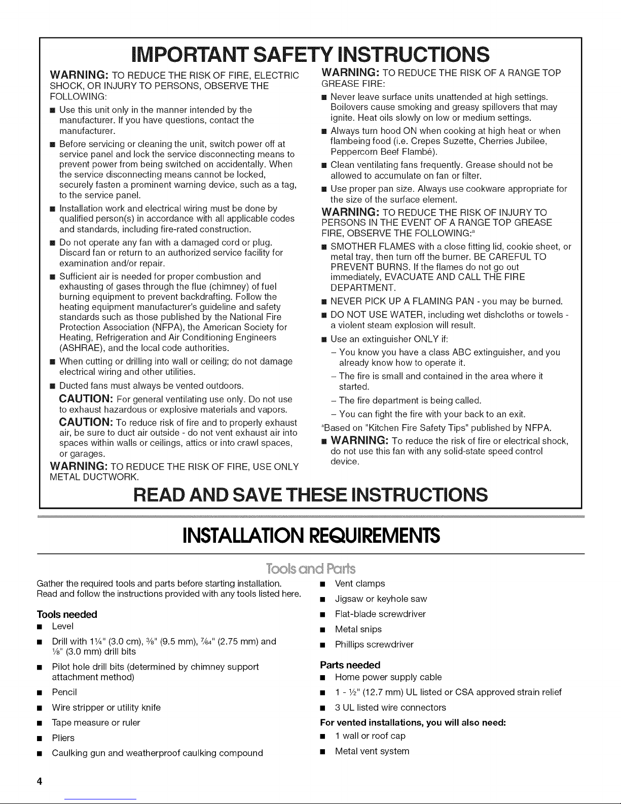
Gather the required tools and parts before starting installation.
Read and follow the instructions provided with any tools listed here.
Tools needed
• Level
• Drill with 11¼"(3.0 cm), 3/8"(9.5 mm), 7/64"(2.75 mm) and
1/8"(3.0 mm) drill bits
• Pilot hole drill bits (determined by chimney support
attachment method)
• Pencil
• Wire stripper or utility knife
• Tape measure or ruler
• Pliers
• Caulking gun and weatherproof caulking compound
• Vent clamps
• Jigsaw or keyhole saw
• Flat-blade screwdriver
• Metal snips
• Phillips screwdriver
Parts needed
• Home power supply cable
• 1 - 1/2"(12.7 mm) UL listed or CSA approved strain relief
• 3 UL listed wire connectors
For vented installations, you will also need:
• 1 wall or roof cap
• Metal vent system
Page 5

For non-vented (recirculating) installations, you will also
need:
• Charcoal Filter Kit Part Number W10412939 for non-vented
(recirculating) installations only. See "Assistance or Service"
section to order.
• 6" (15.2 cm) round metal vent duct. Length required is
determined by ceiling height.
Parts supplied
Remove parts from packages. Check that all parts are included.
• Hood ventilator assembly with vent transition, back draft
damper, canopy glass, retainer brackets, rubber seals, and
light bulb installed.
• Metal grease filter
• 66 - 4.2 x 8 mm screws (T20®tdrive)
• 4 - 5 x 45 mm screws (#2 Phillips drive)
• T10 Torx®tadapter
• T20 ®Torx®adapter
• 4-Vent covers
• 4 - Plastic vent clips
• Mounting template
• Upper horizontal support bracket
• Horizontal support
• 8- Vertical supports
• 2 - Vent cover supports
• Air deflector (for non-vented/recirculating installations)
Product Dimensions
C
D
A. 12_" (31.1cm)
B. 13_/' (33.5 cm)
C. "29_" (75.6 cm)min. 44 _" (113.8 cm) max.
*'29_" (75.6cm) min.491_,, (126.5 cm) max.
D. 3 ½" (8.9 cm)
E.30" (76.2 cm)
F.25_/' (64.0 cm)
*Vented installations only
**Non-vented (recirculating) installations only
Installation Dimensions
IMPORTANT: Observe all governing codes and ordinances.
Have a qualified technician install the range hood. It is the
installer's responsibility to comply with installation clearances
specified on the model/serial rating plate. The model/serial rating
plate is located behind the left filter on the rear wall of the vent
hood.
Canopy hood location should be away from strong draft areas,
such as windows, doors and strong heating vents.
Cabinet opening dimensions that are shown must be used. Given
dimensions provide minimum clearance.
Grounded electrical outlet is required. See "Electrical
Requirements" section.
Because of the size and weight of this island hood, the chimney
support must be securely attached to the ceiling.
• For plaster or drywall ceilings, the chimney support must be
attached to joists. If this is not possible, you must build a
support structure behind the plaster or drywall. The support
structure must be able to support 80 Ibs (36.6 kg).
The range hood is factory set for venting through the roof or wall.
For non-vented (recirculating) Installation see "Non-vented
(recirculating) Installation" in "Install Range Hood" section.
Charcoal Filter Kit Part Number W10412939 is available from
your dealer or an authorized parts distributor.
All openings in ceiling and wall where range hood will be installed
must be sealed.
For Mobile Home Installations
The installation of this range hood must conform to the
Manufactured Home Construction Safety Standards, Title 24
CFR, Part 328 (formerly the Federal Standard for Mobile Home
Construction and Safety, Title 24, HUD, Part 280) or when such
standard is not applicable, the standard for Manufactured Home
Installation 1982 (Manufactured Home Sites, Communities and
Setups) ANSI A225.1/NFPA 501A, or latest edition, or with local
codes.
1-®TORX and T20 are registered trademarks of Saturn Fasteners, Inc.
T
B
1
C
D
!
A
1
A. Countertop height
B. Hood height from ceiling to bottom of the range
hood filter surface: D-A-C=B
C. Hood height: 24" (61.0 cm) min. from electric
cooking surface, 27" (68.6 cm) min. from gas
cooking surface, suggested 36" (91.4 cm) max.
D. Ceiling height
IMPORTANT:
Minimum distance "C": 24" (61.0 cm) from electric cooking
surface, 27" (68.6 cm) from gas cooking surface
Suggested maximum distance "C": 36" (91.4 cm)
Page 6
Thechimneyscanbeadjustedfordifferentceilingheights.See
thefollowingchart.
Vented Installations
Min. ceiling height Max. ceiling height
Electric cooking 7' 8" (2.34 m) 9' 10" (3.0 m)
surface
Gas cooking 7'11" (2.41 m) 9' 10" (3.0 m)
surface
Non-vented (recirculating) Installations
Min. ceiling height Max. ceiling height
Electric cooking 7' 8" (2.34 m) 10' 3" (3.12 m)
surface
Gas cooking 7'11" (2.41 m) 10' 3" (3.12 m)
surface
*NOTE: The range hood chimneys are adjustable and designed
to meet varying ceiling or soffit heights depending on the
distance "C" between the bottom of the range hood and the
cooking surface. For higher ceilings, a Stainless Steel Chimney
Extension Kit Part Number W10272078 is available from your
dealer or an authorized parts distributor. The chimney extension
replaces the chimney shipped with the range hood.
• Vent system must terminate to the outside, except for non-
vented (recirculating) installations.
• Do not terminate the vent system in an attic or other enclosed
area.
• Do not use 4" (10.2 cm) laundry-type wall caps.
• Use metal vent only. Rigid metal vent is recommended. Do
not use plastic or metal foil vent.
• The vent system must have a damper. If the roof or wall cap
has a damper, do not use the damper supplied with the range
hood.
For the most efficient and quiet operation:
• Use a straight run or as few elbows as possible.
• Use no more than three 90 ° elbows.
• Make sure there is a minimum of 24" (61.0 cm) of straight
vent between the elbows if more than 1 elbow is used.
• Do not install 2 elbows together.
• Use vent clamps to seal all joints in the vent system.
• Use caulking to seal exterior wall or roof opening around the
cap.
• The size of the vent should be uniform.
Cold Weather Installations
An additional back draft damper should be installed to minimize
backward cold air flow and a thermal break should be installed to
minimize conduction of outside temperatures as part of the vent
system. The damper should be on the cold air side of the thermal
break.
The break should be as close as possible to where the vent
system enters the heated portion of the house.
Makeup Air
Local building codes may require the use of makeup air systems
when using ventilation systems greater than specified CFM of air
movement. The specified CFM varies from locale to locale.
Consult your HVAC professional for specific requirements inyour
area.
Venting Methods
This island hood is factory set for venting through the roof.
A 6" (15.2 cm) round vent system is needed for installation (not
included). The hood exhaust opening is 6" (15.2 cm) round.
NOTE: Flexible vent is not recommended. Flexible vent creates
back pressure and air turbulence that greatly reduce
performance.
Vent system can terminate either through the roof or wall. To vent
through a wall, a 90° elbow is needed.
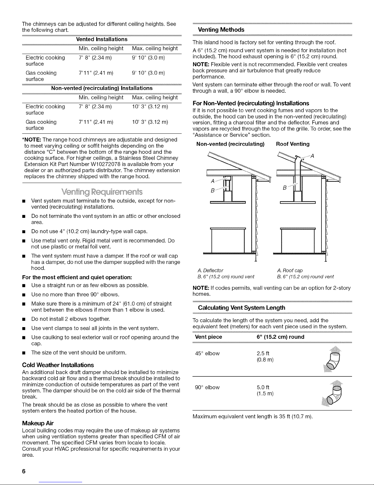
For Non-Vented (recirculating) Installations
If it is not possible to vent cooking fumes and vapors to the
outside, the hood can be used in the non-vented (recirculating)
version, fitting a charcoal filter and the deflector. Fumes and
vapors are recycled through the top of the grille. To order, see the
"Assistance or Service" section.
Non-vented (recirculating) Roof Venting
....; A
A. Deflector
B. 6" (15.2 cm) round vent
NOTE: If codes permits, wall venting can be an option for 2-story
homes.
A. Roof cap
B. 6" (15.2 cm) round vent
Calculating Vent System Length
To calculate the length of the system you need, add the
equivalent feet (meters) for each vent piece used in the system.
Vent piece 6" (15.2 cm) round
45° elbow 2.5 ft
(0.8 m)
90° elbow 5.0 ft
(1.5 m)
Maximum equivalent vent length is 35 ft (10.7 m).
6
Page 7
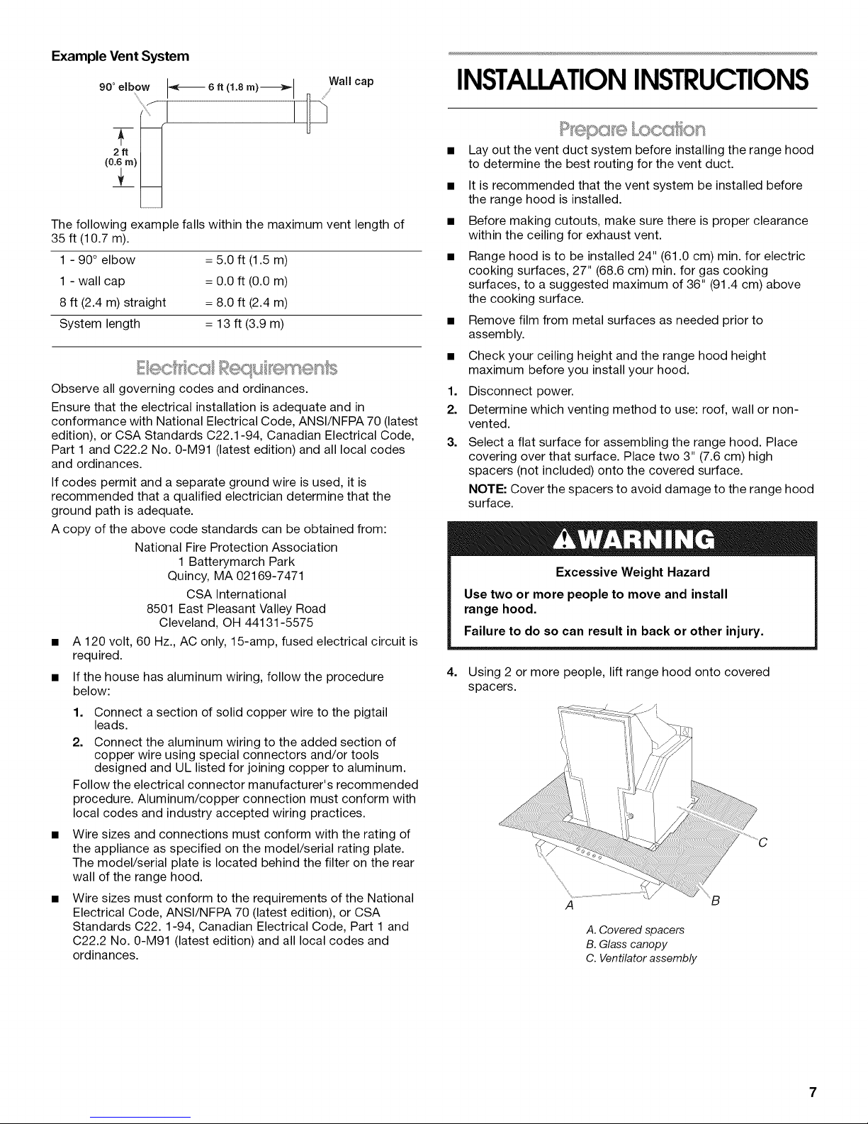
Example Vent System
90°elbow I-,_-_ 6. d.8 m)_l Wall cap
The following example falls within the maximum vent length of
35 ft (10.7 m).
1 - 90° elbow = 5.0 ft (1.5 m)
1 - wall cap = 0.0 ft (0.0 m)
8 ft (2.4 m) straight = 8.0 ft (2.4 m)
System length = 13 ft (3.9 m)
Observe all governing codes and ordinances.
Ensure that the electrical installation is adequate and in
conformance with National Electrical Code, ANSl/NFPA 70 (latest
edition), or CSA Standards C22.1-94, Canadian Electrical Code,
Part 1 and C22.2 No. 0-M91 (latest edition) and all local codes
and ordinances.
If codes permit and a separate ground wire is used, it is
recommended that a qualified electrician determine that the
ground path is adequate.
A copy of the above code standards can be obtained from:
National Fire Protection Association
1 Batterymarch Park
Quincy, MA 02169-7471
CSA International
8501 East Pleasant Valley Road
Cleveland, OH 44131-5575
• A 120 volt, 60 Hz., AC only, 15-amp, fused electrical circuit is
required.
• If the house has aluminum wiring, follow the procedure
below:
1. Connect a section of solid copper wire to the pigtail
leads.
2. Connect the aluminum wiring to the added section of
copper wire using special connectors and/or tools
designed and UL listed for joining copper to aluminum.
Follow the electrical connector manufacturer's recommended
procedure. Aluminum/copper connection must conform with
local codes and industry accepted wiring practices.
Wire sizes and connections must conform with the rating of
the appliance as specified on the model/serial rating plate.
The model/serial plate is located behind the filter on the rear
wall of the range hood.
Wire sizes must conform to the requirements of the National
Electrical Code, ANSI/NFPA 70 (latest edition), or CSA
Standards C22.1-94, Canadian Electrical Code, Part 1 and
C22.2 No. 0-M91 (latest edition) and all local codes and
ordinances.
INSTALLATIONINSTRUCTIONS
• Lay out the vent duct system before installing the range hood
to determine the best routing for the vent duct.
• It is recommended that the vent system be installed before
the range hood is installed.
• Before making cutouts, make sure there is proper clearance
within the ceiling for exhaust vent.
• Range hood is to be installed 24" (61.0 cm) min. for electric
cooking surfaces, 27" (68.6 cm) min. for gas cooking
surfaces, to a suggested maximum of 36" (91.4 cm) above
the cooking surface.
• Remove film from metal surfaces as needed prior to
assembly.
• Check your ceiling height and the range hood height
maximum before you install your hood.
1. Disconnect power.
2. Determine which venting method to use: roof, wall or non-
vented.
3. Select a flat surface for assembling the range hood. Place
covering over that surface. Place two 3" (7.6 cm) high
spacers (not included) onto the covered surface.
NOTE: Cover the spacers to avoid damage to the range hood
surface.
Excessive Weight Hazard
Use two or more people to move and install
range hood.
Failure to do so can result in back or other injury.
4. Using 2 or more people, lift range hood onto covered
spacers.
A
A. Covered spacers
B. Glass canopy
C. Ventilator assembly
Page 8

Range Hood Mounting Screws Installation
1. Determine and mark the centerline on the ceiling where the
range hood will be installed, considering the requirements for
ceiling support structures. See the "Location Requirements"
section. Make sure the range hood is centered over the
cooking surface.
2. Tape template in place on the ceiling at the marked
centerline. The line for the front of the range hood should be
parallel to the front of the cooktop.
1. Position the 4 vertical supports (A) with the notches at the
bottom and attach to the range hood using 16 - 4.2 x 8 mm
T20®screws. Use a T20®Torx®drive (or T20®adapter
provided) to tighten all assembly screws.
2. Attach the horizontal support (B) using 8 - 4.2 x 8 mm T20 ®
screws.
B
im
A
............. _a
A
........ _a
3. Use a pencil to mark the mounting screws, wire access and
duct hole locations on the ceiling.
NOTE: Mounting hole locations should be into a ceiling
support structure capable of holding 80 Ibs (36.6 kg).
Remove the template.
4. Drill 4 - 3/le"(4.8 mm) pilot holes for mounting the upper
horizontal support.
Complete Preparation
1. Determine the required location for the home power supply
cable and drill a 1/2"(1.3 cm) diameter hole for wire access.
2. Run 1/2"(1.3 cm) conduit and wires or home power supply
cable according to the National Electrical Code or CSA
Standards and local codes and ordinances. There must be
enough 1/2"conduit and wires or home power supply cable
from the fused disconnect (or circuit breaker) box to make the
connection in the hood's electrical terminal box.
NOTE: Do not reconnect power until installation is complete.
3. For vented installations only: Using a jigsaw or keyhole
saw, cut a 61/2'' (16.5 cm) diameter hole for the vent duct.
4. Attach the upper horizontal support bracket with 4 - 5 x
45 mm #2 Phillips wood screws.
NOTE: Upper horizontal support screws must be into a
ceiling support structure capable of holding 80 Ibs (36.6 kg).
A. Verficalsuppor_
B. Horizon_l support
C. Notched end
3.
Attach a second set of vertical supports (A) and set the
vertical height (B). See "Installation Dimensions" in the
"Location Requirements" section to help determine the
desired dimension for vertical height "B."
Secure with 16 - 4.2 x 8 mm T20 ®screws.
A
B
I
A. Vertical supports
B. Vertical height
A
A. Upper horizontal support
B. 5 x 45 mm screws (#2 Phillips drive)
8
_B
Non-Vented (recirculating) Installation
1.
Attach the air deflector to the upper horizontal support using
2 - 4.2 x 8 mm T20 ®mounting screws.
B
A. Deflector
B. 2 4.2x8mm ®
- T20 mounting screws
2.
Measure the length of 6" (15.2 cm) duct needed to connect
the transition to the deflector.
NOTE: Vent should fit up inside the deflector 1" (2.5 cm)
minimum.
Page 9
3. Install vent between the transition and the deflector.
NOTE: To make vent installation easier, temporarily remove
the deflector from the chimney support bracket and replace
after vent section is in place.
4. Seal all connections with vent clamps. Continue with "Range
Hood Installation" in this section.
Range Hood Installation
1.
Using 2 or more people, lift the range hood assembly and
attach it by snapping the vertical supports to the spring clips
in the upper horizontal support bracket that is mounted to the
ceiling.
2=
Install 16 - 4.2 x 8 mm T20®screws, and tighten to secure.
A ....
! !
A. Mounting screws
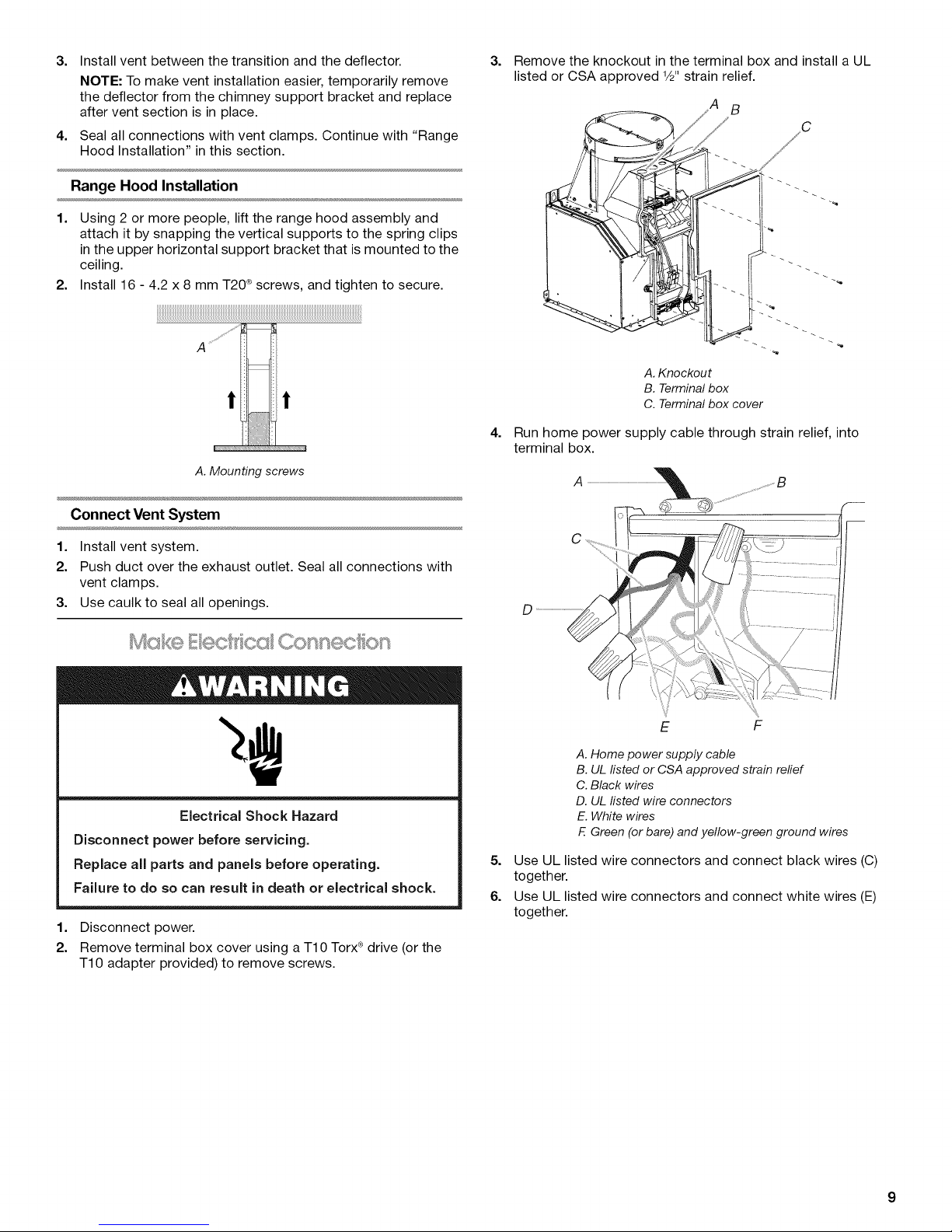
3=
Remove the knockout in the terminal box and install a UL
listed or CSA approved 1/2"strain relief.
A. Knockout
B. Terminal box
C. Terminal box cover
4=
Run home power supply cable through strain relief, into
terminal box.
Connect Vent System
1. Install vent system.
2. Push duct over the exhaust outlet. Seal all connections with
vent clamps.
3. Use caulk to seal all openings.
Electrical Shock Hazard
Disconnect power before servicing.
Replace all parts and panels before operating.
Failure to do so can result in death or electrical shock.
1. Disconnect power.
2. Remove terminal box cover using a TIO Torx ®drive (or the
T10 adapter provided) to remove screws.
E F
A. Home power supply cable
B. UL listed or CSA approved strain relief
C. Black wires
D. UL listed wire connectors
E. White wires
E Green (or bare) and yellow-green ground wires
5. Use UL listed wire connectors and connect black wires (C)
together.
6. Use UL listed wire connectors and connect white wires (E)
together.
Page 10

Electrical Shock Hazard
Electrically ground blower.
Connect ground wire to green and yellow ground wire
in terminal box.
Failure to do so can result in death or electrical shock.
2=
Slide the upper duct covers into place, and insert 3 tabs on
each side of the duct covers into the mating slots of the
vertical duct cover supports. Slide the duct covers up until
the springs "click" and the tabs are locked in place.
______________________________________________________________________________________________________________________________B
7. Connect green (or bare) ground wire from home power supply
to yellow-green ground wire (F) in terminal box using UL listed
wire connectors.
8. Tighten strain relief screw.
9. Install terminal box cover.
10. Check that all light bulbs are secure in their sockets.
11. Reconnect power.
NOTE: Remove the film from the vertical duct cover supports and
the duct covers.
1. Attach the vertical duct cover supports using 8 - 4.2 x 8 mm
T20®screws.
A
A. 4.2 x 8 mm T20®screws
B. Vertical duct cover support
A. Upper duct cover
B. Spring
3=
Slide the lower duct covers over the upper duct covers.
4.
Attach the lower duct covers together using a plastic bracket
at each top and bottom corner of the lower duct covers
(4 places).
A. Upper duct cover
B. Lower duct cover
C. Plastic brackets
1. For non-vented (recirculating) installations only, install
charcoal filters onto the metal filters. See the "Range Hood
Care" section.
2. Install metal filters. See the "Range Hood Care" section.
3. Check the operation of the range hood blower and light. See
the "Range Hood Use" section.
If range hood does not operate, check to see whether a
circuit breaker has tripped or a household fuse has blown.
NOTE: To get the most efficient use from your new range hood,
read the "Range Hood Use" section.
10
Page 11
RANGE HOOD USE
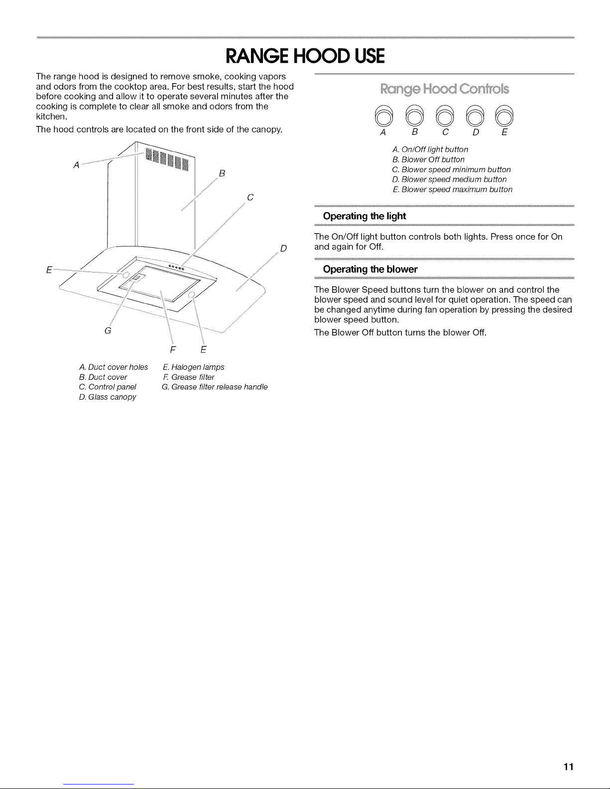
The range hood is designed to remove smoke, cooking vapors
and odors from the cooktop area. For best results, start the hood
before cooking and allow it to operate several minutes after the
cooking is complete to clear all smoke and odors from the
kitchen.
The hood controls are located on the front side of the canopy.
B
C
D
F E
A. Duct cover holes
B. Duct cover
C. Control panel
D. Glass canopy
E. Halogen lamps
F. Grease filter
G. Grease filter release handle
©©©©©
A B C D E
A. On/Off light button
B. Blower Off button
C. Blower speed minimum button
D. Blower speed medium button
E.Blower speed maximum button
Operating the light
The On/Off light button controls both lights. Press once for On
and again for Off.
Operating the blower
The Blower Speed buttons turn the blower on and control the
blower speed and sound level for quiet operation. The speed can
be changed anytime during fan operation by pressing the desired
blower speed button.
The Blower Off button turns the blower Off.
11
Page 12
RANGEHOOD CARE
IMPORTANT: Clean the hood and grease filters frequently
according to the following instructions. Replace grease filters
before operating hood.
Exterior Surfaces:
To avoid damage to the exterior surface, do not use steel wool or
soap-filled scouring pads.
Always wipe dry to avoid water marks.
Cleaning Method:
• Liquid detergent soap and water, or all-purpose cleanser
• Wipe with damp soft cloth or nonabrasive sponge, then rinse
with clean water and wipe dry.
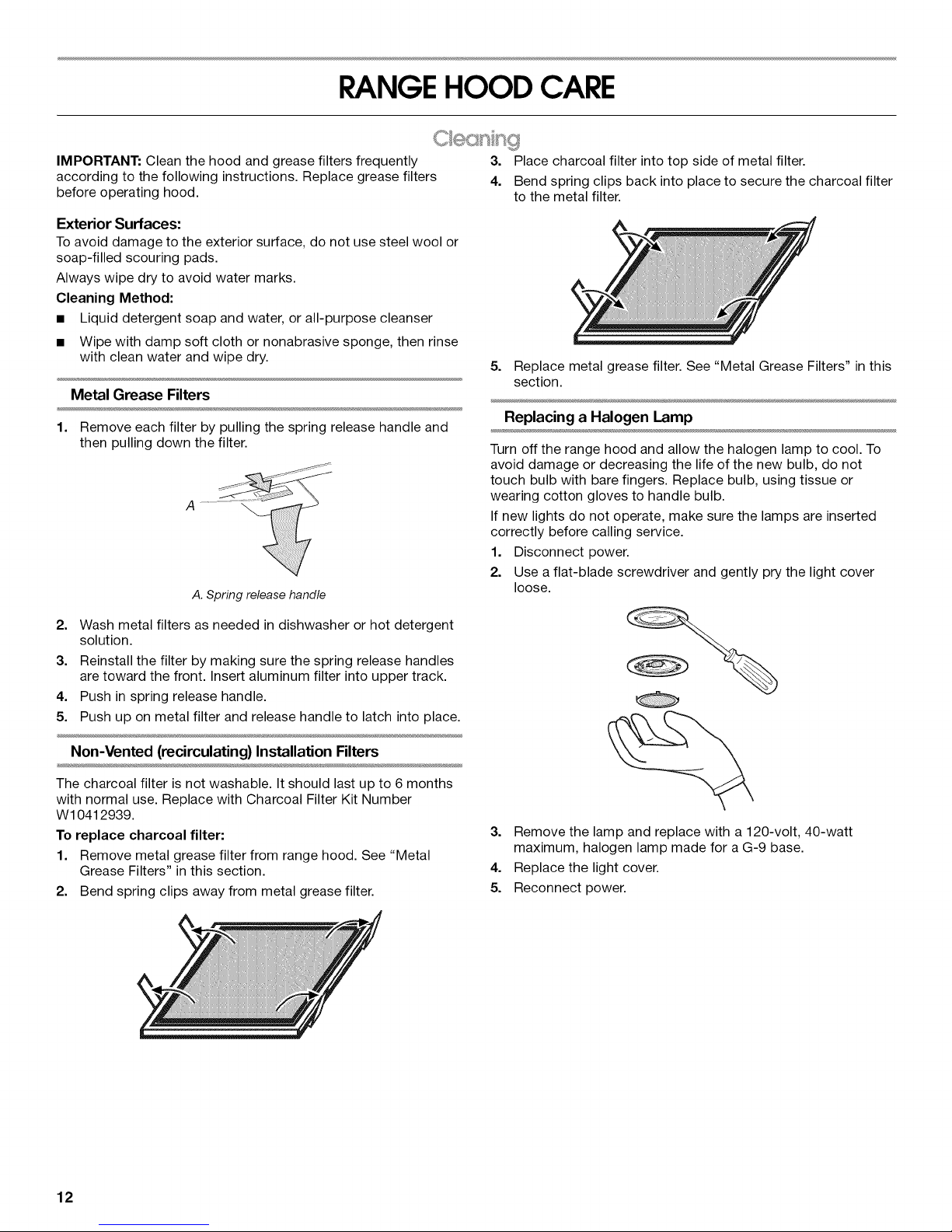
Metal Grease Filters
1. Remove each filter by pulling the spring release handle and
then pulling down the filter.
A .........................
A.Spring releasehandle
3. Place charcoal filter into top side of metal filter.
4. Bend spring clips back into place to secure the charcoal filter
to the metal filter.
5. Replace metal grease filter. See "Metal Grease Filters" in this
section.
Replacing a Halogen Lamp
Turn off the range hood and allow the halogen lamp to cool. To
avoid damage or decreasing the life of the new bulb, do not
touch bulb with bare fingers. Replace bulb, using tissue or
wearing cotton gloves to handle bulb.
If new lights do not operate, make sure the lamps are inserted
correctly before calling service.
1. Disconnect power.
2. Use a flat-blade screwdriver and gently pry the light cover
loose.
2. Wash metal filters as needed in dishwasher or hot detergent
solution.
3. Reinstall the filter by making sure the spring release handles
are toward the front. Insert aluminum filter into upper track.
4. Push in spring release handle.
5. Push up on metal filter and release handle to latch into place.
Non-Vented (recirculating) Installation Filters
The charcoal filter is not washable. It should last up to 6 months
with normal use. Replace with Charcoal Filter Kit Number
W10412939.
To replace charcoal filter:
1. Remove metal grease filter from range hood. See "Metal
Grease Filters" in this section.
2. Bend spring clips away from metal grease filter.
3. Remove the lamp and replace with a 120-volt, 40-watt
maximum, halogen lamp made for a G-9 base.
4. Replace the light cover.
5. Reconnect power.
12
Page 13

_ Neu Gnd
WIRING DIAGRAM
R
O_
w 0,- ._
BR
0 -J
BK _
0 n m
BR _
O..J a_
Y
03
03
r-
W
@
BK
Y
Y
Switch Operation
Position
Off
Lamps
LowSpeed
MedSpeed
HighSpeed
Function
Noconnection
Brown-Yellow
(L- hA)
Brown-White
(L-1 /
Brown-Red
(L-2)
Brown-Black
(h-3)
MotorCharacteristics
PowerSupply 120VAC
Frequency 60Hz
Y
PowerAbsorption 240Watts
MotorResistance
(Ohms)
Blue- Black 28.8
SE123A
Blue- Gray 30.3
Blue- Red 37.7
Blue- White 45.1
RoomTemp. 73.4°F(23°C'
13
Page 14
ASSISTANCEOR SERVICE
Before calling for assistance or service, please check to see
whether a circuit breaker has tripped or a household fuse has
blown. It may save you the cost of a service call. If you still need
help, follow the instructions below.
When calling, please know the purchase date and the complete
model and serial number of your appliance. This information will
help us to better respond to your request.
If you need replacement parts
If you need to order replacement parts, we recommend that you
use only factory specified parts. Factory specified parts will fit
right and work right because they are made with the same
precision used to build every new IKEA® appliance.
To locate factory specified parts in your area, call us or your
nearest designated service center.
Call the Whirlpool Customer eXperience Center
toll free: 1-866-664-2449,
Our consultants provide assistance with:
• Features and specifications on our full line of appliances.
• Installation information.
• Use and maintenance procedures.
• Accessory and repair parts sales.
• Specialized customer assistance (Spanish speaking, hearing
impaired, limited vision, etc.).
• Referrals to local dealers, repair parts distributors, and
service companies. Whirlpool designated service technicians
are trained to fulfill the product warranty and provide after-
warranty service, anywhere in the United States.
To locate the Whirlpool designated service company in your
area, you can also look in your telephone directory Yellow
Pages.
For further assistance
If you need further assistance, you can write to Whirlpool
Corporation with any questions or concerns at:
IKEA Brand Home Appliances
Customer eXperience Center
553 Benson Road
Benton Harbor, MI 49022-2692
Please include a daytime phone number in your correspondence.
Call the Whirlpool Canada LP Customer eXperience Centre toll
free: 1-866-664-2449.
Our consultants provide assistance with:
• Features and specifications on our full line of appliances.
• Use and maintenance procedures.
• Accessory and repair parts sales.
• Referrals to local dealers, repair parts distributors, and
service companies. Whirlpool Canada LP designated service
technicians are trained to fulfill the product warranty and
provide after-warranty service, anywhere in Canada.
For further assistance
If you need further assistance, you can write to Whirlpool
Canada LP with any questions or concerns at:
Customer eXperience Centre
Whirlpool Canada LP
200 - 6750 Century Ave.
Mississauga, Ontario L5N 0B7
Please include a daytime phone number in your correspondence.
Charcoal Filter Kit
(for non-vented installations only)
Order Part Number W10412939
Chimney Extension Kit
Order Part Number W10272078
6" (15.2 cm) Makeup Air Kit
(consult local building codes)
Order Part Number W10446915
14
Page 15
IKEAMAJOR APPLIANCEWARRANTY
How long is the IKEA limited warranty valid?
This limited warranty is valid for five years from the date of purchase, when this major appliance is operated and maintained according
to instructions attached to or furnished with the product, unless the appliance is named LAGAN in which case this limited warranty is
valid for one year from the date of purchase. This limited warranty is valid only in the United States or Canada and applies only when the
major appliance is used in the country in which it was purchased. Proof of original purchase date is required to obtain service under this
limited warranty.
Which appliances are not covered by the IKEA five (5) year limited warranty?
For major appliances named "LAGAN," this limited warranty is valid for one year from the date of purchase.
Who will execute the service?
This limited warranty is provided by Whirlpool Corporation or Whirlpool Canada LP (hereafter "Whirlpool"). Service must be provided by
a Whirlpool designated service company.
What does this limited warranty cover?
The limited warranty will pay for factory specified parts and repair labor to correct defects in materials or workmanship that existed
when the major appliance was purchased. The exceptions are specified under the headline "What is not covered under this limited
warranty?".
What will be done to correct the problem?
The designated service company will examine the product and decide, at its sole discretion, if it is covered under this limited warranty.
If considered covered, the designated service company will then repair the defect. Your sole and exclusive remedy under this limited
warranty shall be product repair as provided herein.
What is not covered under this limited warranty?
• Service calls to correct the installation of your major appliance, to instruct you on how to use your major appliance, to replace or
repair house fuses, or to correct house wiring or plumbing.
• Service calls to repair or replace appliance light bulbs, air filters or water filters. Consumable parts are excluded from warranty
coverage.
• Replacement parts or repair labor if this major appliance is used for other than normal, single-family household use or when it is used
in a manner that is inconsistent to published user or operator instructions and/or installation instructions.
• Damage resulting from accident, alteration, misuse, abuse, fire, flood, acts of God, improper installation, installation not in
accordance with electrical or plumbing codes, or use of consumables or cleaning products not approved for use.
• Cosmetic damage, including scratches, dents, chips or other damage to the finish of your major appliance, unless such damage
results from defects in materials or workmanship and is reported within 30 days from the date of purchase.
• Any food loss or medicine loss due to refrigerator or freezer product failures.
• Pick up and delivery. This major appliance is intended to be repaired in your home.
• Repairs to parts or systems resulting from unauthorized modifications made to the appliance.
• Expenses for travel and transportation for product service if your major appliance is located in a remote area where service by an
authorized servicer is not available.
• The removal and reinstallation of your major appliance if it is installed in an inaccessible location or is not installed in accordance with
published installation instructions.
• Replacement parts or repair labor on major appliances with original model/serial numbers that have been removed, altered or cannot
be easily determined.
The cost of repair or replacement under these excluded circumstances shall be borne by the customer.
Disclaimer of Implied Warranties
IMPLIED WARRANTIES, INCLUDING ANY IMPLIED WARRANTY OF MERCHANTABILITY OR IMPLIED WARRANTY OF FITNESS FOR
A PARTICULAR PURPOSE, ARE LIMITED TO FIVE YEARS (ONE YEAR FOR MAJOR APPLIANCES NAMED "LAGAN") OR THE
SHORTEST PERIOD ALLOWED BY LAW. Some states and provinces do not allow limitations on the duration of implied warranties of
merchantability or fitness, so this limitation may not apply to you. This warranty gives you specific legal rights, and you also may have
other rights that vary from state to state or province to province.
Limitation of Remedies; Exclusion of Incidental and Consequential Damages
YOUR SOLE AND EXCLUSIVE REMEDY UNDER THIS LIMITED WARRANTY SHALL BE PRODUCT REPAIR AS PROVIDED HEREIN.
WHIRLPOOL SHALL NOT BE LIABLE FOR INCIDENTAL OR CONSEQUENTIAL DAMAGES. Some states and provinces do not allow
the exclusion or limitation of incidental or consequential damages, so these limitations and exclusions may not apply to you. This
warranty gives you specific legal rights, and you also may have other rights that vary from state to state or province to province.
How to reach us if you need our service
If outside the 50 United States and Canada, contact your authorized IKEA retailer to determine if another warranty applies.
If you need service, please read the Installation Instructions and/or the "Troubleshooting" section of the Use & Care Guide before
contacting us. If you need additional help, do not hesitate to contact us in the U.S.A. and Canada at 1-866-664-2449.
2/09
15
Page 16

Keep this book and your sales slip together for future
reference. You must provide proof of purchase or installation
date for in-warranty service.
Write down the following information about your major appliance
to better help you obtain assistance or service if you ever need it.
You will need to know your complete model number and serial
number. You can find this information on the model and serial
number label located on the product.
Dealer name
Address
Phone number
Model number
Serial number
Purchase date
16
Page 17
SEGURIDADDELACAMPANA PARACOCINA
Su seguridad y la seguridad de los demos es muy importante.
Hemos incluido muchos mensajes importantes de seguridad en este manual yen su electrodomestico. Lea y obedezca siempre
todos los mensajes de seguridad.
Este es el simbolo de advertencia de seguridad.
Este simbolo le llama la atenci6n sobre peligros potenciales que pueden ocasionar la muerte o una lesi6n a
usted y a los demas.
Todos los mensajes de seguridad iran a continuaci6n del simbolo de advertencia de seguridad y de la palabra
"PELIGRO" o "ADVERTENCIA". Estas palabras significan:
Si no sigue las instrucciones de inmediato, usted puede
morir o sufrir una lesibn grave.
Si no sigue las instrucciones, usted puede morir o sufrir
una lesibn grave.
Todos los mensajes de seguridad le diran el peligro potencial, le diran c6mo reducir las posibilidades de sufrir una lesi6n y Io que
puede suceder si no se siguen las instrucciones.
17
Page 18
INSTRUCCIONES IMPORTANTES DE SEGURIDAD
ADVERTENCIA: PARA REDUCIR EL RIESGO DE
INCENDIOS, CHOQUE EL¢:CTRICO O LESIONES A
PERSONAS, OBSERVE LO SIGUIENTE:
m Use esta unidad solo de la manera para la que fue
diseSada por el fabricante. Si tiene preguntas, pOngase en
contacto con el fabricante.
m Antes de dar servicio o limpiar esta unidad, apague el
suministro de energia en el panel de servicio, y bloquee los
medios de desconexiOn del servicio para evitar que se
encienda accidentalmente el suministro de energfa.
Cuando el medio de desconexiOn del servicio no se pueda
bloquear, sujete de manera segura un dispositivo de
advertencia prominente, como podria ser una etiqueta, al
panel de servicio.
m Eltrabajo de instalaciOn y cableado se debe Ilevar a cabo
por una persona(s) calificada(s), en conformidad con todos
los cOdigos y est#tndares aplicables, incluyendo
construcciones clasificadas como resistentes al fuego.
m No opere ning0n ventilador que tenga un cable o enchufe
daSado. Deshagase del ventilador o devuOIvalo a un lugar
de servicio autorizado para que sea examinado y/o
reparado.
m Es necesario que haya suficiente aire para la adecuada
combustion y ventilaciOn de gases a trav_s del conducto (la
chimenea) del equipo que consume combustible, para
evitar que ocurra contratiro. Siga la gufa y los estb,ndares
de seguridad del fabricante del equipo de calefacciOn,
como serian aqu_llos publicados por National Fire
Protection Association (NFPA) (AsociaciOn nacional de
protecciOn contra incendios), American Society for Heating,
Refrigeration and Air Conditioning Engineers (ASHRAE)
(Sociedad estadounidense para ingenieros de calefacciOn,
refrigeraciOn y acondicionamiento de aire) y las autoridades
de cOdigos locales.
m Cuando corte o taladre en una pared o techo, no daSe el
cableado ni otros servicios pt_blicos.
m Los ventiladores con conductos siempre deben dar salida al
aire hacia el exterior.
CUIDADO: Para usarse solamente en ventilaciOn
comOn. No Io utilice para ventilar materiales y vapores
peligrosos o explosivos.
CUIDADO: Para reducir el riesgo de incendio y para
ventilar el aire adecuadamente, asegOrese de dirigir el
conducto de ventilaciOn hacia el exterior - noventile el aire
de salida a espacios dentro de paredes o techos, aticos,
espacios angostos o garajes.
ADVERTENClA: PARA REDUCIR EL RIESGO DE
INCENDIO, SOLO USE CONDUCTOS MET,&.LICOS.
ADVERTENCIA: PARA REDUCIR EL RIESGO DE
INCENDIO PROVOCADO POR GRASA EN LA SUPERFICIE
DE LA ESTUFA:
m Nunca deje las unidades de superficie sin vigilancia cuando
estOn en ajustes altos. Los derrames por hervor causan
salpicaduras grasosas y humeantes, las cuales pueden
encenderse. Caliente los aceites lentamente y con ajustes
bajos o medios.
m Siempre ENCIENDA la campana cuando cocine con calor
alto o cuando flamee alimentos (por ejemplo, crepes
Suzette, cerezas Jubileo y flameado de came de res con
pimienta).
m Limpie los ventiladores con frecuencia. No permita que se
acumule la grasa en el ventilador o en el filtro.
m Use cacerolas del tamaSo adecuado. Siempre use
utensilios de cocciOn que sean los adecuados para el
tamaSo del elemento de la superficie.
ADVERTENClA: PARA REDUCIR EL RIESGO DE
LESIONES A PERSONAS SI SE PRENDE FUEGO EN LA
SUPERFICIE DE LA ESTUFA OCASIONADO POR GRASA,
OBSERVE LO SIGUIENTE: a
m EXTINGA LAS LLAMAS con una tapa que encaje muy
bien, una bandeja para galletas o una bandeja metb,lica, y
luego apague el quemador. TENGA CUIDADO PARA
EVITAR QUEMADURAS. Si las llamas no se extinguen de
inmediato, EVACUE Y LLAME AL DEPARTAMENTO DE
BOMBEROS.
m NUNCA AGARRE UNA CACEROLA QUE ESTE
ARDIENDO - podria quemarse.
m NO UTILICE AGUA ni artfculos de limpieza con agua,
incluyendo paSos para vajilla o toallas mojadas - podria
ocurrir una explosion de vapor violenta.
m SOLO use un extinguidor si:
- Sabe a ciencia cierta que tiene un extinguidor de clase
ABC y ya sabe cOmo utilizarlo.
- El incendio es pequeSo y se encuentra contenido en el
lugar en donde se iniciO.
- Ha Ilamado al departamento de bomberos.
- Puede apagar el fuego con su espalda mirando hacia
una salida.
aBasado en "Consejos de seguridad para fuegos de cocina",
publicado por el NFPA (AsociaciOn nacional de protecciOn
contra incendios).
m ADVERTENClA: A fin de reducir el riesgo de incendio
o de choque elOctrico, no use este ventilador con ningOn
dispositivo semiconductor para el control de la velocidad.
LEA Y GUARDE ESTAS INSTRUCCIONES
18
Page 19

REQUISITOSDEINSTALACION
ReQna las herramientas y piezas necesarias antes de comenzar
la instalaci6n. Lea y siga las instrucciones provistas con
cualquiera de las herramientas detalladas aquL
Herramientas necesarias
• Nivel
• Taladro con brocas de 1W' (3,0 cm), %" (9,5 mm), %/'
(2,75 mm) y V8"(3,0 mm)
• Brocas para el orificio piloto (elegidas segQn el metodo de
sujecion del soporte de la chimenea)
• Lapiz
• Pelacables o cuchillo de uso general
• Cinta de medir o regla
• Pinzas
• Pistola para calafateo y masilla para calafateo a prueba de
agua
• Abrazaderas para ducto
• Sierra de vaiven o sierra caladora
• Destornillador de hoja plana
• Tijeras de hojalatero
• Destornillador Phillips
Piezas necesarias
• Cable de suministro electrico domestico
• 1 protector de cables de _/2"(12,7 mm) que esten en la lista
de UL o aprobados por CSA
• 3 conectores para hilos que esten en la lista de UL
Para las instalaciones con ducto de escape, tambi6n
necesitara:
• 1 cubierta para pared o techo
• Sistema de ventilacion metalico
Para las instalaciones sin ducto de escape (con
recirculacibn), tambi6n necesitara:
• Juego de filtro de carbon, pieza nQmero W10412939,
solamente para las instalaciones sin ducto de escape (con
recirculacion). Vea la seccion "Ayuda o servicio tecnico" para
hacer pedidos.
• Sistema de ventilacion redondo de metal de 6" (15,2 cm). La
Iongitud necesaria esta determinada por la altura del techo.
Piezas suministradas
Saque las piezas de los paquetes. Verifique que esten todas las
piezas.
• Ensamblaje del ventilador de la campana con pieza de
transicion del ducto, compuerta de contratiro, escudete de
vidrio, soportes de retencion, sellos de goma y foco de luz
instalados.
• Filtro de metal para grasa
• 66 tornillos de 4,2 x 8 mm (destornillador T20 ®t)
• 4 tornillos de 5 x 45 mm (destornillador Phillips N° 2)
t®TORX y T20 son marcas registradas de Saturn Fasteners, Inc.
• Adaptador Torx®tT10
• Adaptador Torx®T20®
• 4 cubiertas para ducto
• 4 sujetadores de plastico para ducto
• Plantilla de montaje
• Soporte horizontal superior de apoyo
• Soporte horizontal
• 8 soportes verticales
• 2 soportes para la cubierta del ducto
• Desviador de aire (para las instalaciones sin ducto de escape/
con recirculacion)
_C_ ,¸_i'_ _ I/_Q_/_
IMPORTANTE: Observe todos los codigos y ordenanzas
aplicables.
Haga que un tecnico capacitado instale la campana para cocina.
Es la responsabilidad del instalador cumplir con los espacios de
instalacion especificados en la placa con la clasificacion de
modelo/serie. La placa con clasificacion de modelo/serie esta
ubicada detras del filtro izquierdo, en la pared posterior de la
campana para cocina.
La ubicacion de la campana con escudete deberA estar lejos de
zonas con corrientes fuertes de aire, tales como ventanas,
puertas u orificios de calefaccion con un flujo intenso.
Deben usarse las dimensiones de la abertura del armario que se
muestran. Las dimensiones proporcionadas proveen los
espacios minimos.
Se requiere un enchufe electrico con conexion a tierra. Vea la
seccion "Requisitos electricos".
Debido al tamafio y al peso de esta campana para isla, el soporte
de la chimenea deberA sujetarse firmemente al techo.
• Para techos de yeso o muro en seco, el soporte de la
chimenea debera estar sujeto alas vigas. Si esto no es
posible, debera construir una estructura de soporte detrAs de
la pared de yeso o muro en seco. La estructura de soporte
debera tener capacidad para soportar un peso de 80 Ib
(36,6 kg).
La campana para estufa se ha ajustado de fabrica para tener una
ventilacion a traves del techo o de la pared.
Para ver la instalacion sin ducto de escape (con recirculacion),
consulte "lnstalacion sin ducto de escape (con recirculacion)" en
la seccion "lnstalacion de la campana para cocina". El filtro de
carbon, pieza nOmero W10412939, esta disponible con su
distribuidor o un distribuidor de piezas autorizado.
Se deben sellar todas las aberturas en el techo y la pared en
donde se va a instalar la campana para cocina.
Para la instalaci6n en casas rodantes
La instalacion de esta campana para cocina debe ajustarse a los
Manufactured Home Construction Safety Standards (Estandares
de seguridad y construccion de casas fabricadas), Titulo 24 CFR,
Parte 328 (anteriormente conocidos como Federal Standard for
Mobile Home Construction and Safety [Estandar federal para la
seguridad y construccion de casas rodantes], Titulo 24, HUD
Parte 280), o cuando dicho estandar no sea aplicable, el
estandar Manufactured Home Installation (Estandar para
instalacion en casas fabricadas) de 1982 (Manufactured Home
Sites, Communities and Setups [Obras, comunidades y
proyectos de casas fabricadas]), ANSI A225.1/NFPA 501A, o la
Oltima edicion o con los codigos locales.
19
Page 20

Medidas del producto
_J ".... _i}-_.-. !
Las chimeneas pueden regularse para las diferentes alturas del
techo. Vea el cuadro siguiente.
Instalaciones con ventilacibn
Altura minima del Altura maxima del
techo techo
Superficie de 7' 8" (2,34 m) 9' 10" (3,0 m)
coccion electrica
Superficie de 7'11" (2,41 m) 9' 10" (3,0 m)
C
D
coccion a gas
Instalaciones sin ducto de escape (con recirculacibn)
Altura minima del Altura maxima del
techo techo
Superficie de 7' 8" (2,34 m) 10' 3" (3,12 m)
coccion electrica
Superficie de 7'11" (2,41 m) 10' 3" (3,12 m)
coccion a gas
A. 12_" (31,1 cm)
B. 13_" (33,5 cm)
C. *29_" (75,6 cm)como mfnimo, 441_,, (113,8cm)como m&ximo
*'29_" (75,6cm) como mfnimo, 49 _" (126,5 cm) como m&ximo
O.3½" (8,9 cm)
E. 30" (76,2 cm)
F.25 _" (64,0 cm)
*lnstalaciones con ducto de escape solamente
**lnstalaciones sin ducto de escape (con recirculacion)
solamente
Dimensiones de instalaci6n
1
B
1
C
A
D
J
A. Altura del mostrador
B. Altura de la campana desde el techo hasta la parte inferior de la
superficie del filtro de la campana para cocina: D-A-C = B
C. Altura de la campana: 24" (61,0 cm) como mfnimo desde la
superficie de cocci6n el_ctrica, 27" (68,6 cm) como mfnimo desde
la superficie de cocci6n a gas, 36" (91,4 cm) como m_ximo
sugerido
D. Altura del techo
IMPORTANTE:
Distancia minima "C": 24" (61,0 cm) desde la superficie de
coccion electrica, 27" (68,6 cm) desde la superficie de
coccion a gas
Distancia maxima sugerida "C": 36" (91,4 cm)
*NOTA: Las chimeneas de la campana para cocina son
ajustables y se han disefiado para varias alturas de techos o
sofitos, dependiendo de la distancia "C" entre la parte inferior
de la campana de cocina y la superficie de coccion. Para techos
m_s altos, un Juego de extension para chimenea de acero
inoxidable, pieza nOmero W10272078, se encuentra disponible
con su distribuidor o un distribuidor de piezas autorizado. La
extension para chimenea reemplaza la chimenea que se envio
con la campana para cocina.
cS®qus os4@ "0 '
• El sistema de ventilaci6n debe terminar en el exterior,
excepto para las instalaciones sin ducto de escape (con
recirculaci6n).
• No dirija la salida del sistema de ventilaci6n hacia el desvan u
otra area cerrada.
• No utilice cubiertas de pared de tipo para lavanderia de 4"
(10,2 cm).
• Utilice ducto de escape de metal Qnicamente. Se recomienda
un ducto de escape de metal rigido. No utilice un ducto de
escape de plastico ni de aluminio.
• El sistema de ventilaci6n debe tener una compuerta. Si la
cubierta del techo o la pared tiene una compuerta, no use la
compuerta provista con la campana de cocina.
Para obtener el funcionamiento mas eficaz y silencioso:
• Use un tendido recto o con la menor cantidad de codos
posible.
• No use mas de 3 codos de 90°.
• AsegQrese de que haya un minimo de 24" (61,0 cm) de ducto
de escape recto entre los codos, si se utiliza m_s de 1 codo.
• No instale 2 codos lado a lado.
• Use abrazaderas para ducto para sellar todas las juntas en el
sistema de ventilaci6n.
• Utilice masilla de calafateo para sellar la abertura exterior de
la pared o el techo alrededor de la cubierta.
• El tamafio del ducto de escape debe ser uniforme.
Instalaciones en climas frios
Como parte del sistema de ventilacion, se debera instalar una
compuerta de contratiro adicional para minimizar el flujo de aire
frio hacia atrAs, y un dispositivo de interrupcion termico para
reducir la conduccion de las temperaturas exteriores. La
compuerta deberA estar en el lado del aire frio del dispositivo de
interrupcion termico.
20
Page 21

El dispositivo de interrupcion debera estar Io mas cerca posible
del lugar donde el sistema de ventilacion entra a la parte con
calefaccion de la casa.
Aire de complemento
Los codigos locales de construccion podrian requerir el uso de
sistemas de aire de complemento, en el caso de que se usen
sistemas de ventilacion con un movimiento de aire mayor a los
CFM (pies cQbicos por minuto) especificados. Los pies cQbicos
por minuto especificados varian entre Iocalidades. Consulte a su
profesional de Calefaccion, Ventilacion y Acondicionamiento de
Aire (HVAC) para obtener informacion sobre los requisitos
particulares en su zona.
M_todos de ventilacibn
Esta campana para isla se ha ajustado de fabrica para tener una
ventilacion a traves del techo.
Se requiere un sistema de ventilacion redondo de 6" (15,2 cm)
para la instalacion (no incluido). La abertura de ventilacion de la
campana es redonda, de 6" (15,2 cm).
NOTA" No se recomienda el uso de ductos de escape flexibles.
Los ductos de escape flexibles crean contrapresion y turbulencia
de aire, Io cual reduce el desempe_o en gran medida.
El sistema de ventilacion debe terminar a traves del techo o la
pared. Para colocar el ducto a traves de la pared, se necesita un
codo de 90 °.
C6mo calcular el largo del sistema de ventilaci6n
Para calcular el largo del sistema que necesita, sume los pies
(metros) equivalentes para cada porcion de ducto de escape que
se utilice en el sistema.
Porcibn de ducto de Redondo de 6"
escape (15,2 cm)
Codo de 45° 2,5 pies
(0,8 m)
Codo de 90° 5,0 pies
(1,5 m)
El largo maximo equivalente del ducto es 35 pies (10,7 m).
Ejemplo de sistema de ventilaci6n
cododeoo°i_ o (,,.m> CubiertadeJapared
Para las instalaciones sin ducto de escape (con
recirculaci6n)
Si no es posible ventilar el humo y los vapores de la coccion al
exterior, la campana puede usarse en la version sin ducto de
escape (con recirculacion), colocando un filtro de carbon y el
desviador. El humo y los vapores son reciclados a traves de la
parte superior de la rejilla. Para hacer pedidos, consulte la
seccion "Ayuda o servicio tecnico".
Sin ducto de escape (con Ventilacibn a trav_s del
recirculacibn) techo
A. Desviador
B. Ducto de escape redondo de
6" (15,2 cm)
NOTA: Si los codigos Io permiten, la ventilacion a traves de la
pared puede ser una opcion para los hogares de 2 pisos.
A. Cubierta del techo
B. Ducto de escape redondo de
6" (15,2 cm)
El siguiente ejemplo se encuentra dentro del largo mfiximo de
35 pies (10,7 m).
1 codo de 90° = 5,0 pies (1,5 m)
1 cubierta de pared = 0,0 pies (0,0 m)
Porcion recta de 8 pies (2,4 m) = 8,0 pies (2,4 m)
Largo del sistema = 13 pies (3,9 m)
Observe todos los c6digos y reglamentos aplicables.
AsegQrese de que la instalacion electrica sea adecuada y en
conformidad con el National Electrical Code (Codigo Nacional
Electrico), ANSl/NFPA 70 (Qltima edicion) o las normas de CSA
C22.1-94, Canadian Electrical Code (Codigo Canadiense de
Electricidad), Parte 1 y C22.2 N° 0-M91 (Qltima edicion), y todos
los codigos y ordenanzas locales.
Si los codigos Io permiten y se emplea un alambre de conexion a
tierra separado, es recomendable que un electricista calificado
determine si la trayectoria de conexion a tierra es adecuada.
Usted puede obtener una copia de las normas de los codigos
arriba indicadas en:
National Fire Protection Association
1 Batterymarch Park
Quincy, MA 02169-7471
CSA International
8501 East Pleasant Valley Road
Cleveland, OH 44131-5575
• Se necesita un circuito electrico de 120 voltios, 60 hertzios,
CA solamente, de 15 amperios y protegido con fusibles.
21
Page 22
Si la casa tiene cableado de aluminio, siga el procedimiento a
continuacion:
1. Conecte una seccion de alambre de cobre solido a los
conductores flexibles.
2. Conecte el cableado de aluminio a la seccion a_adida de
alambre de cobre usando conectores especiales y/o
herramientas dise_adas y de la lista de UL para unir el
cobre al aluminio.
Siga el procedimiento recomendado por el fabricante del
conector electrico. La conexion de cobre/aluminio deberA
hacerse en conformidad con los codigos locales y las
prActicas de cableado aceptadas por la industria.
INSTRUCCIONESDEINSTALACION
• Los tama_os de los cables y las conexiones deben hacerse
de acuerdo con la clasificacion del electrodomestico, como
se especifica en la placa de clasificacion del modelo/de la
serie. La placa del modelo/de la serie esta ubicada destras
del filtro, en la pared posterior de la campana para cocina.
• El calibre de los cables debe hacerse de acuerdo a los
requisitos del National Electrical Code (Codigo Nacional
Electrico), ANSI/NFPA 70 (Oltima edicion) o las normas de
CSA C22.1-94 Canadian Electrical Code (Codigo
Canadiense de Electricidad), Parte 1 y C22.2 N° 0-M91
(Oltima edicion), y todos los codigos y ordenanzas locales.
Arregle el sistema del ducto de escape antes de instalar la 3.
campana para cocina, para determinar el mejor tendido para
el ducto de escape.
Se recomienda que el sistema de ventilacion sea instalado
antes de que se instale la campana para cocina.
Antes de hacer los recortes, asegOrese que haya suficiente
espacio libre dentro del techo para el ducto de escape.
La campana para cocina deberA instalarse a 24" (61,0 cm)
como minimo para las superficies de coccion electricas, 27"
(68,6 cm) como minimo para las superficies de coccion a
gas, hasta un maximo sugerido de 36" (91,4 cm) por encima
de la superficie de coccion.
Quite la pelicula de las superficies de metal, ya que es
necesario hacerlo antes del ensamblaje.
Revise la altura del techo y la altura maxima de la campana
para cocina antes de instalar su campana.
1.
Desconecte el suministro de energia.
2.
Decida qu6 metodo de ventilacion usar: a traves del techo,
de la pared o sin ducto.
Seleccione una superficie plana para ensamblar la campana
para cocina. Cubra dicha superficie. Coloque dos
espaciadores de 3" (7,6 cm) de alto (no incluidos) sobre la
superficie cubierta.
NOTA: Cubra los espaciadores para evitar da_os en la
superficie de la campana para cocina.
Peligro de Peso Excesivo
Use dos o mas personas para mover e instalar
la campana de cocina.
No seguir esta instrucci6n puede ocasionar una lesi6n
en la espalda u otro tipo de lesiones.
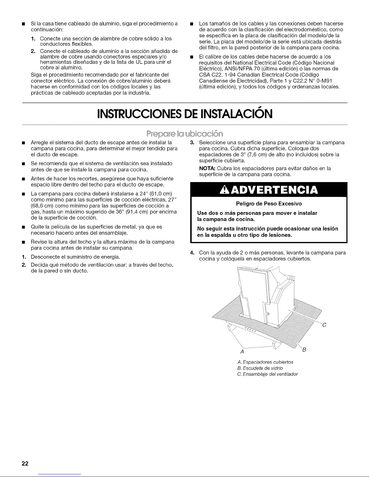
4. Con la ayuda de 2 o mas personas, levante la campana para
cocina y coloquela en espaciadores cubiertos.
22
A
A. Espaciadores cubiertos
B. Escudete de vidrio
C. Ensamblaje del ventilador
Page 23

Instalaci6n de los tornillos de montaje de la campana
para cocina
1. Determine y marque la linea central sobre el techo en donde
se va a instalar la campana para cocina, teniendo en cuenta
los requisitos para las estructuras de soporte del techo. Vea
la seccion "Requisitos de ubicacion". Cerciorese de que la
campana para cocina este centrada sobre la superficie de
coccion.
2.
Pegue con cinta adhesiva la plantilla en su lugar en el techo,
en la linea central marcada. La linea para la parte frontal de la
campana para cocina deber_ ser paralela a la parte frontal de
la superficie de coccion.
3. Marque con un lapiz las ubicaciones de los tornillos de
montaje, el acceso al cableado y el orificio del ducto en el
techo.
NOTA: Las ubicaciones de los orificios de montaje deberAn
estar en una estructura de apoyo con capacidad para
sostener 80 Ib (36,6 kg).
Retire la plantilla.
4. Taladre 4 orificios piloto de 3/ld' (4,8 mm) para montar el
soporte horizontal superior.
4.
Sujete el soporte de apoyo horizontal superior con 4 tornillos
Phillips N° 2 para madera de 5 x 45 mm.
NOTA: Los tornillos del soporte horizontal superior deberAn
estar en una estructura de apoyo con capacidad para
sostener 80 Ib (36,6 kg).
A. Soporte horizontal superior
B. Tornillos de 5 x 45 mm (destornillador Phillips N °2)
1. Coloque los 4 soportes verticales (A) con las muescas en la
base y suj@telos a la campana para estufa con 16 tornillos
T20®de 4,2 x 8 mm. Use un destornillador Torx®T20 ®(o el
adaptador T20®provisto) para apretar todos los tornillos de
ensamblaje.
2. Sujete el soporte horizontal (B) con 8 tornillos T20 ®de 4,2 x
8 mm.
Complete la preparacibn
1. Determine la ubicacion necesaria para el cable de suministro
electrico del hogar y taladre un orificio con un diametro de 1/2"
(1,3 cm) para obtener acceso a los cables.
2. Haga pasar el conducto y los cables de 1/2"(1,3 cm) o el cable
de suministro electrico del hogar de acuerdo al National
Electrical Code (Codigo electrico nacional) o las normas de
CSA (Asociacion de normalizacion canadiense) y los codigos
y ordenanzas locales. Debe haber suficiente conducto y
alambres de 1/2"o de cable de suministro electrico del hogar
de la caja de desconexion con fusible (o cortacircuitos) para
hacer la conexion en la caja electrica de terminales de la
campana.
NOTA: No reconecte la electricidad hasta que se haya
completado la instalacion.
3. Solamente para las instalaciones con ducto de escape:
Haga un orificio de 61/2"(16,5 cm) de diametro para el ducto
de escape con una sierra de vaiven o sierra caladora.
A. Soportes verticales
B. Soporte horizontal
C. Extreme con muesca
3.
Sujete el segundo conjunto de soportes verticales (A) y fije la
altura vertical (B). Vea "Dimensiones de instalacion" en la
seccion "Requisitos de ubicacion" para que le ayude a
determinar la dimension deseada para la altura vertical "B".
Asegure con 16 tornillos T20 ®de 4,2 x 8 mm.
A
A
B
i
L
A.Soportes verticales
B.Altura vertical
J
±
23
Page 24

Inslalaci6nsinduclo de escape (con recirculaci6n)
1. Sujete el desviador de aireal soporte horizontal superior con
2 tornillos de montajeT20®de 4,2 x 8 mm.
B
A. Desviador
B. 2 tornillos de montaje T20®de 4,2 x 8 mm
2. Mida la Iongitud del ducto de 6" (15,2 cm) necesaria para
conectar la pieza de transicion al desviador.
NOTA" El ducto deberA encajar dentro del desviador 1"
(2,5 cm) como minimo.
3. Instale el ducto entre la pieza de transicion y el desviador.
NOTA" Para hacer mas facil la instalacion del ducto, quite
provisoriamente el desviador del soporte de apoyo para la
chimenea y vuelva a colocarlo despu6s de que este en su
lugar la seccion del ducto.
4. Selle todas las conexiones con las abrazaderas para ducto.
ContinOe con "lnstalacion de la campana para cocina" en
esta seccion.
Instalacibn de la campana para cocina
Peligro de Choque EI6ctrico
Desconecte el suministro de energia antes de darle
mantenimiento.
Vuelva a colocar todos los componentes y paneles
antes de hacerlo funcionar.
No seguir estas instrucciones puede ocasionar
la muerte o choque el_ctrico.
1. Desconecte el suministro de energia.
2. Quite la cubierta de la caja de terminales con un
destornillador Torx®T10 (o el adaptador T10 provisto) para
quitar los tornillos.
3. Quite el disco removible que esta en la caja de terminales e
instale un protector de cables de 1/2"que este en la lista de
UL o este aprobado por CSA.
J_/ !A ,B C
/ /
/,_ / ¢
1. Con la ayuda de dos o mas personas, levante el ensamblaje
de la campana para cocina y sujetelo encajando los soportes
verticales a los sujetadores de resorte en elsoporte de apoyo
horizontal superior que esta montado en el techo.
2. Instale 16 tornillos T20 ®de 4,2 x 8 mm y aprietelos para
asegurarlos.
A .........
!
I
A. Tornillos de montaje
Conexi6n del sistema de ventilaci6n
1. Instale el sistema de ventilacion.
2. Empuje el ducto sobre la salida de escape. Selle todas las
conexiones con las abrazaderas para ducto.
3. Use masilla de calafateo para sellar todas las aberturas.
!
A. Disco removible
B. Caja de terminales
C. Cubierta de la caja de terminales
24
Page 25
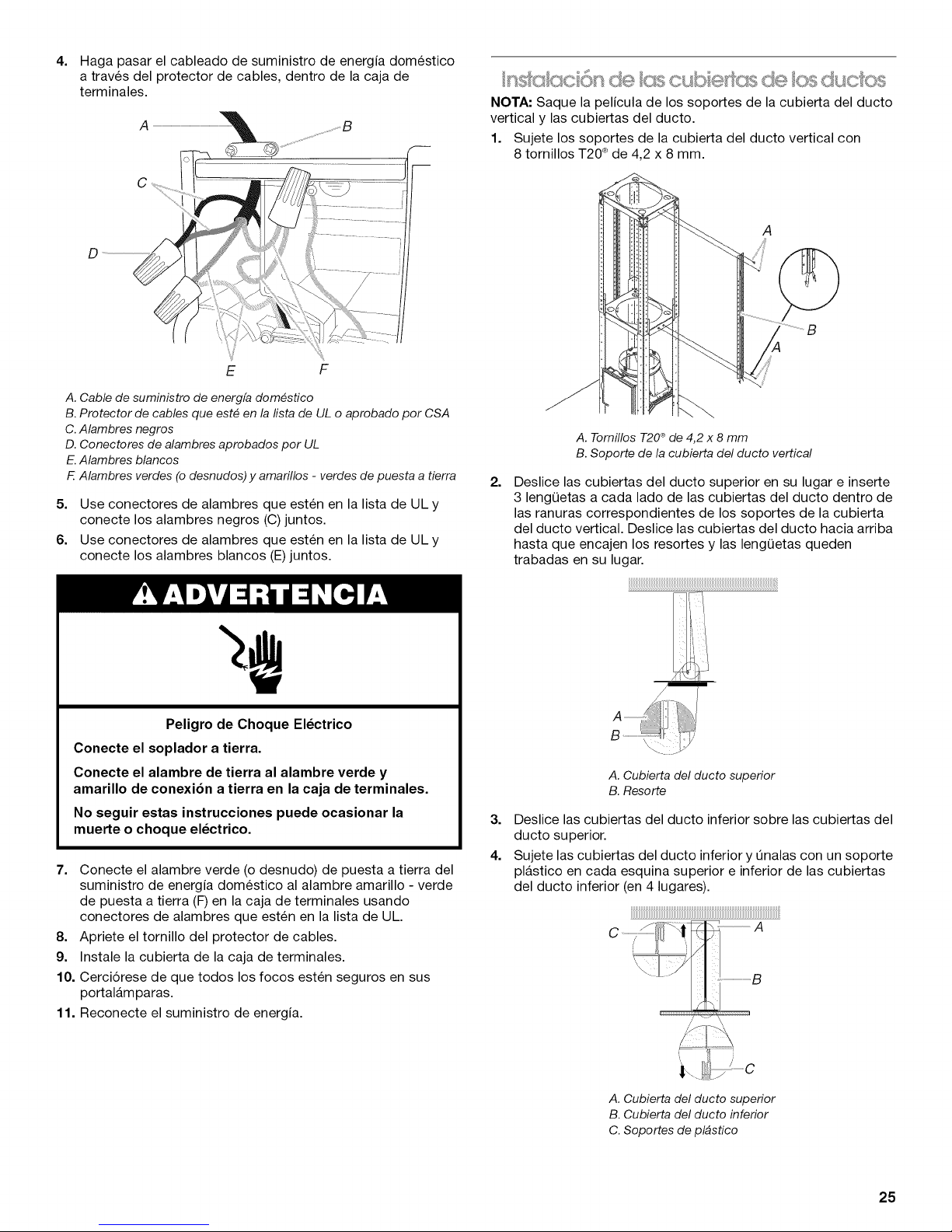
4=
Haga pasar el cableado de suministro de energia domestico
a traves del protector de cables, dentro de la caja de
terminales.
A
E F
A. Cable de suministro de energfa dom#stico
B. Protector de cables que est# en la fista de UL o aprobado per CSA
C.Alambres negros
D. Conectores de alambres aprobados per UL
E.Alambres blancos
F.Alambres verdes (o desnudos) y amarillos - verdes de puesta a tierra
5. Use conectores de alambres que esten en la lista de UL y
conecte los alambres negros (C) juntos.
6. Use conectores de alambres que esten en la lista de UL y
conecte los alambres blancos (E)juntos.
IOTA: Saque la pelicula de los soportes de la cubierta del ducto
vertical y las cubiertas del ducto.
1. Sujete los soportes de la cubierta del ducto vertical con
8 tornillos T20 ®de 4,2 x 8 mm.
A
A. Tornillos T20®de 4,2 x 8 mm
B. Soporte de la cubierta del ducto vertical
2=
Deslice las cubiertas del ducto superior en su lugar e inserte
3 lengQetas a cada lado de las cubiertas del ducto dentro de
las ranuras correspondientes de los soportes de la cubierta
del ducto vertical. Deslice las cubiertas del ducto hacia arriba
hasta que encajen los resortes y las lengQetas queden
trabadas en su lugar.
Peligro de Choque El_ctrico
Conecte el soplador a tierra.
Conecte el alambre de tierra al alambre verde y
amarillo de conexi6n a tierra en la caja de terminales.
No seguir estas instrucciones puede ocasionar la
muerte o choque el_ctrico.
7. Conecte el alambre verde (o desnudo) de puesta a tierra del
suministro de energia domestico al alambre amarillo - verde
de puesta a tierra (F) en la caja de terminales usando
conectores de alambres que esten en la lista de UL.
8. Apriete el tornillo del protector de cables.
9. Instale la cubierta de la caja de terminales.
10. Cerciorese de que todos los focos esten seguros en sus
portalamparas.
11. Reconecte el suministro de energia.
A. Cubierta del ducto superior
B. Resorte
3=
Deslice las cubiertas del ducto inferior sobre las cubiertas del
ducto superior.
4.
Sujete las cubiertas del ducto inferior y Onalas con un soporte
plastico en cada esquina superior e inferior de las cubiertas
del ducto inferior (en 4 lugares).
_t_ A
.................1 rl
B
A. Cubierta del ducto superior
B. Cubierta del ducto inferior
C. Soportes de pl#stico
25
Page 26
1. Solamente para las instalaciones sin ventilacion (con
recirculacion), instale los filtros de carbon sobre los filtros de
metal. Consulte la seccion "Cuidado de la campana para
cocina".
2. Instale los filtros de metal. Consulte la seccion "Cuidado de la
campana para cocina".
USODELA CAMPANA PARACOCINA
La campana para cocina se ha disefiado para remover humo,
vapores provenientes de la coccion y olores del Area de la
superficie de coccion. Para obtener mejores resultados,
encienda la campana antes de cocinar y permita que funcione
por varios minutos despues de haber cocinado, para que quite
todo el humo y los olores de la cocina.
Los controles de la campana estan ubicados en el lado frontal
del escudete.
B
ji'
C
csn csc6n
3.
Verifique el funcionamiento del soplador de la campana para
cocina y la luz. Consulte la seccion "Uso de la campana para
cocina".
Si la campana de cocina no funciona, revise si se ha
disparado un cortacircuitos o si se ha quemado un fusible
domestico.
NOTA: Para obtener un uso mas eficaz de su nueva campana de
cocina, lea la seccion "Uso de la campana para cocina".
COC _%@
@@(909@
A B C D E
A. BotSn de encendido/apagado de la luz
B. BotSn de apagado del soplador
C. Bot6n de velocidad mfnima del soplador
D. Bot6n de velocidad media del soplador
E.Bot6n de velocidad m_xima del soplador
C6mo utilizar la luz
A. Orificios de la cubierta del ducto
B. Cubierta del ducto
C. Panel de control
D. Escudete de vidrio
F E
E.Luces de hal6geno
F. Filtro para grasa
G. Manija para liberar el filtro
para grasa
El boton de Encendido/Apagado controla ambas luces. Presione
una vez paraEncendido y nuevamente paraApagado.
D
,/¢'
C6mo utilizar el soplador
Los botones de velocidad del soplador encienden el soplador y
controlan la velocidad y el nivel de sonido de este para un
funcionamiento silencioso. La velocidad se puede cambiar en
cualquier momento mientras el ventilador este funcionando,
presionando el boton de la velocidad deseada del soplador.
El soplador se apaga con el boton de apagado.
26
Page 27

CUIDADO DELA CAMPANA PAPACOCINA
IMPORTANTE: Limpie con frecuencia la campana y los filtros
para grasa de acuerdo alas instrucciones a continuacion. Vuelva
a colocar los filtros para grasa antes de poner a funcionar la
campana.
Superficies exteriores:
Para evitar dafios a la superficie exterior, no use estropajos de
acero ni jabonosos.
Siempre sequela con un patio para evitar manchas de agua.
M6todo de limpieza:
• Detergente liquido y agua o producto de limpieza general
• Limpielo con un patio suave hOmedo o una esponja no
abrasiva, enju_guelo con agua limpia y sequelo con un patio.
Filtros de metal para grasa
1.
Quite cada filtro jalando la manija de liberacion con resorte y
luego jalando el filtro hacia abajo.
A .................
A.Manija de liberacidn con resorte
2. Lave los filtros de metal cuando sea necesario en la
lavavajillas o con una solucion caliente de detergente.
3. Vuelva a instalar el filtro asegurandose de que las manijas de
liberacion con resorte esten mirando hacia el frente. Inserte el
filtro de ahminio dentro de la guia superior.
4. Empuje hacia dentro la manija de liberacion con resorte.
5. Empuje el filtro de metal hacia arriba y suelte la manija para
que se trabe en su hgar.
3. Coloque el filtro de carbon en el lado superior del filtro de
metal.
4. Doble los sujetadores con resorte nuevamente hacia dentro
en su hgar para asegurar el filtro de carbon al filtro de metal.
5. Vuelva a colocar el filtro metalico para grasa. Consulte "Filtro
metalico para grasa" en esta seccion.
C6mo reemplazar una luz de hal6geno
Apage la campana para cocina y espere a que se enfrie la hz de
halogeno. Para evitar dafiar o disminuir la vida Qtil del nuevo
foco, no Io toque con los dedos descubiertos. Reemplace el foco
usando un pafiuelo de papel o guantes de algodon para
manipular el foco.
Si los nuevos focos no funcionan, cerciorese de que se hayan
insertado correctamente antes de Ilamar para solicitar servicio.
1. Desconecte el suministro de energia.
2. Use un destornillador de hoja plana y haga palanca
cuidadosamente para quitar la cubierta del foco.
Filtros para las instalaciones sin ducto de escape (con
recirculaci6n)
El filtro de carbon no se puede lavar. Debera durar hasta 6 meses
con el uso normal. Reemplacelo con el Juego de filtro de carbon
nOmero W10412939.
Para reemplazar el filtro de carbbn:
1. Quite el filtro metalico para grasa de la campana para cocina.
Consulte "Filtro metalico para grasa" en esta seccion.
2. Doble los sujetadores con resorte para separarlos del filtro de
metal para grasa.
3. Quite el foco y reemplacelo con un foco de halogeno de
120 voltios, 40 vatios como maximo, fabricado para una base
G-9.
4. Vuelva a colocar la cubierta del foco.
5. Reconecte el suministro de energia.
27
Page 28
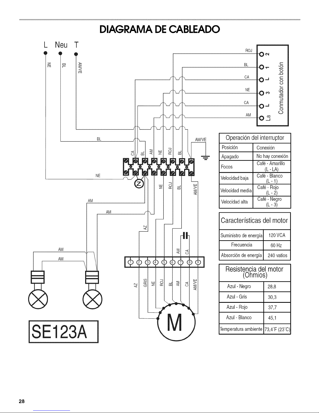
_ Neu T
DIAGRAMA DECABLEADO
ROJ
AM
NE
BL
AM
BL 0_- "o
CA O. J g
NE _
0
0
0 _, -_
CA O..i
AM
03
AMNE
@
Operaci6n del interruptor
Posici6n
Apagado
Focos
Velocidadbaja
Velocidadmedia
Velocidadalta
Conexi6n
Nohayconexi6n
Oaf@-Amarillo
Oaf_- Blanoo
Oaf@-Rojo
Oaf@-Negro
(L- LA)
(L-l)
(h- 2)
(h-3)
O
o
Caracterfsticasdel motor
AM
SE123A
Suministrodeenergia 120VCA
Frecuencia 60 Hz
Absorci6ndeenergia 240vatios
Resistenciadel motor
(Ohmios)
Azul- Negro 28,8
Azul- Gris 30,3
Azul- Rojo 37,7
Azul- Blanco 45,1
Ternperaturaarnbiente73,4°F(23°0)
28
Page 29
AYUDA O SERVlCIOTECNI¢O
Antes de solicitar ayuda o servicio tecnico, por favor revise si se
ha disparado un cortacircuitos o si se ha quemado un fusible
domestico. Esto le podrA ahorrar el costo de una visita de
servicio tecnico. Si considera que aOn necesita ayuda, siga las
instrucciones que aparecen a continuacion.
Cuando Ilame, tenga a mano la fecha de compra y el nOmero
completo del modelo y de la serie de su electrodomestico. Esta
informacion nos ayudarA a atender mejor a su pedido.
Si necesita piezas de repuesto
Si necesita pedir piezas de repuesto, recomendamos que use
Onicamente piezas especificadas de fabrica. Las piezas
especificadas de fabrica encajaran bien y funcionaran bien ya
que estan confeccionadas con la misma precision empleada en
la fabricacion de cada electrodomestico nuevo de IKEA®.
Para encontrar piezas especificadas de fabrica en su Iocalidad,
Ilamenos o Ilame al centro de servicio tecnico designado mAs
cercano a su Iocalidad.
Llame al centro para la eXperiencia del cliente de Whirlpool
sin costo alguno al: 1-866-664-2449.
Nuestros consultores ofrecen ayuda para"
• Caracteristicas y especificaciones de nuestra linea completa
de electrodomesticos.
• Informacion sobre la instalacion.
• Procedimiento para el uso y mantenimiento.
• Venta de accesorios y partes para reparacion.
• Asistencia especializada para el consumidor (habla hispana,
problemas de audicion, vision limitada, etc.).
Recomendaciones con distribuidores locales, compa_ias que
dan servicio y distribuidores de partes para reparacion. Los
tecnicos de servicio designados por Whirlpool estan
capacitados para cumplir con la garantia del producto y
ofrecer servicio una vez que la garantia termine, en cualquier
lugar de los Estados Unidos.
Para Iocalizar a una compa_ia de servicio designada por
Whirlpool en su Area, tambien puede consultar la seccion
amarilla de su guia telefonica.
Para obtener asistencia adicional
Si necesita asistencia adicional, puede escribir a Whirlpool
Corporation con sus preguntas o dudas a:
IKEA Brand Home Appliances
Customer eXperience Center
553 Benson Road
Benton Harbor, MI 49022-2692
Por favor incluya en su correspondencia un nOmero de telefono
en el que se le pueda Iocalizar durante el dia.
Juego de filtro de carb6n
(solamente para instalaciones sin ducto de escape)
Pida la pieza nQmero W10412939
Juego de extensi6n para chimenea
Pida la pieza nQmeroW10272078
Juego de aire de complemento de 6" (15,2 cm)
(consulte el codigo de construccion local)
Pida la pieza nOmero W10446915
29
Page 30

GARANTIA DELOSELECTRODOMESTICOSPRINCIPALESDEIKEA
&Durante cu&nto tiempo es v&lida la garantia limitada de IKEA?
Esta garantia limitada es valida durante cinco a_os a partir de la fecha de compra, siempre y cuando este electrodomestico principal
haya sido operado y mantenido segOn las instrucciones adjuntas o provistas con el producto, a menos que sea un aparato de nombre
LAGAN, en cuyo caso la garantia limitada serA valida durante un a_o a partir de la fecha de compra. Esta garantia limitada es valida
solamente en Estados Unidos o en Canada y se aplica solamente cuando el electrodomestico principal se use en el pals en el que se
ha comprado. Se requiere una prueba de la fecha de compra original para obtener servicio bajo esta garantia limitada.
&Qud electrodomdsticos no est&n cubiertos bajo la garantia limitada de IKEA de cinco (5)
ahos?
Para los electrodomesticos principales cuyo nombre sea "LAGAN", esta garantia serA valida durante un a_o a partir de la fecha de
compra.
&Qui_n estar& a cargo de Ilevar a cabo el servicio?
Esta garantia limitada es provista por Whirlpool Corporation o Whirlpool Canada LP (en Io sucesivo denominada "Whirlpool"). El
servicio deberA ser suministrado por una compa_ia de servicio designada por Whirlpool.
&Qud es Io que cubre esta garantia limitada?
La garantia limitada pagara por piezas especificadas de fabrica y trabajo de reparacion, para corregir defectos en los materiales o en la
mano de obra existentes en el momento de la compra del electrodomestico principal. Las excepciones se especifican bajo el titulo
"6Qu6 es Io que no esta cubierto bajo esta garantia limitada?".
&Qud se har& para corregir el problema?
La compa_ia designada de servicio examinara el producto y decidira, a su exclusiva discrecion, siesta cubierto bajo esta garantia
limitada. Si considera que esta cubierto, la compa_ia designada de servicio reparara el defecto. Su Onico y exclusivo recurso segOn los
terminos de esta garantia limitada serA el de reparar el producto segOn se estipula en la presente.
&Qud es Io que no est& cubierto bajo esta garantia limitada?
• Visitas de servicio tecnico para corregir la instalacion de su electrodomestico principal, para ense_arle a usar su electrodomestico
principal, para cambiar o reparar fusibles domesticos o para corregir la instalacion electrica o de la tuberia de la casa.
• Visitas de servicio tecnico para reparar o reemplazar focos para electrodomesticos, filtros de aire o filtros de agua. Las piezas de
consumo estan excluidas de la cobertura de la garantia.
• Piezas de repuesto o mano de obra si este electrodomestico principal se usa de un modo diferente al domestico normal de una
familia, o cuando se use de un modo contrario alas instrucciones publicadas para el usuario u operador y/o las instrucciones de
instalacion.
Da_os causados por accidente, alteracion, uso indebido, abuso, incendio, inundacion, actos fortuitos, instalacion incorrecta,
instalacion que no este de acuerdo con los codigos electricos o de plomeria, o el empleo de articulos de consumo o productos de
limpieza no aprobados para ser usados.
Da_os esteticos, incluyendo rayaduras, abolladuras, desportilladuras u otro da_o al acabado de su electrodomestico principal, a
menos que el mismo sea debido a defectos en los materiales o la mano de obra y se informe en un lapso de 30 dias a partir de la
fecha de compra.
Cualquier perdida de comida o de medicamentos debida a fallas del refrigerador o del congelador.
Recogida y entrega. Este electrodomestico principal se ha destinado para ser reparado en su hogar.
Reparaciones de piezas o sistemas como resultado de modificaciones no autorizadas que se hayan efectuado en el
electrodomestico.
Gastos de viaje ytransporte para obtener servicio para el producto, si su electrodomestico principal esta ubicado en un lugar remoto
en el cual no haya disponible un tecnico de servicio autorizado.
La remocion y reinstalacion de su electrodomestico principal, si estuviera instalado en un lugar inaccesible o si no estuviera instalado
de conformidad con las instrucciones de instalacion publicadas.
Piezas de repuesto o mano de obra en electrodomesticos principales con nQmeros de modelo/serie originales que se hayan
removido, alterado o que no puedan ser identificados con facilidad.
El costo de la reparacibn o el reemplazo bajo estas circunstancias excluidas correra por cuenta del cliente.
Exclusibn de garantias implicitas
LAS GARANT[AS IM PL[CITAS,, INCLUYEN DO CUALQUIE,R GARANT[A IMPL[CITA DE COM ERCIABI LIDAD O GARANT[A IMPL[CITA DE
CAPACIDAD PARA UN PROPOSITO PARTICULAR, SERAN LIMITADAS A CINCO ANOS (UN ANO PARA LOS ELECTRODOMC:STICOS
PRINCIPALES DE NOMBRE "LAGAN") O AL PERIODO MAS CORTO PERMITIDO POR LEY.Algunos estados y provincias no permiten
la limitacion de la duracion de garantias implicitas de comerciabilidad o capacidad, de modo que la limitacion arriba indicada quizas no
le corresponda. Esta garantia le otorga derechos legales especificos, yes posible que usted tenga tambien otros derechos que varian
de un estado a otro o de una provincia a otra.
30
Page 31
Limitacibn de recursos; exclusibn de dahos incidentales y consecuentes
SU ONICO Y EXCLUSIVO RECURSO SEGON LOS TI2RMINOS DE ESTA GARANT[A LIMITADA SERA EL DE REPARAR EL PRODUCTO
SEGUN SE ESTIPULA EN LA PRESENTE. WHIRLPOOL NO SE RESPONSABILIZARA POR DANOS INCIDENTALES 0
CONSECUENTES. Algunos estados y provincias no permiten la exclusion o limitacion de dafios incidentales o consecuentes, de modo
que estas limitaciones y exclusiones quizas no le correspondan. Esta garantia le otorga derechos legales especificos, yes posible que
usted tenga tambien otros derechos que varian de un estado a otro o de una provincia a otra.
Cbmo puede ponerse en contacto con nosotros si necesita nuestro servicio
Si usted se encuentra fuera de los cincuenta Estados Unidos y CanadA, pongase en contacto con su vendedor autorizado de IKEA
para determinar si corresponde otra garantia.
Si necesita servicio tecnico, sirvase leer las Instrucciones de instalacion y/o la seccion "Solucion de problemas" del Manual de uso y
cuidado antes de ponerse en contacto con nosotros. Si necesita ayuda adicional, no dude en contactarnos en EE.UU. y Canada al
1-866-664-2449. 2/09
Guarde este libro y su comprobante de compra juntos para
referencia futura. Usted debera proporcionar el comprobante
de la compra o una fecha de instalacibn para obtener
servicio bajo la garantia.
Escriba la siguiente informacion acerca de su electrodomestico
principal para ayudarle mejor a obtener asistencia o servicio
tecnico si alguna vez Ilegara a necesitarlo. Debera tener a mano
el nOmero completo del modelo y de la serie. Usted puede
encontrar esta informacion en la etiqueta con el nOmero de
modelo y de serie ubicada en el producto.
Nombre del distribuidor
Direccibn
Nt_mero de tel_fono
Nt_mero de modelo
Nt_mero de serie
Fecha de compra
31
Page 32

SECURITEDELA HOTTEDECUISINIERE
Votre securite et celle des autres est tres importante.
Nous donnons de nombreux messages de s_curit_ importants dans ce manuel et sur votre appareil m_nager. Assurez-vous de
toujours lire tousles messages de s_curit_ et de vous y conformer.
Ce symbole d'alerte de s_curit_ vous signale les dangers potentiels de d_c_s et de blessures graves & vous
et &d'autres.
Voici le symbole d'alerte de s_curit&
Tousles messages de s_curit_ suivront le symbole d'alerte de s_curit_ et le mot "DANGER" ou
"AVERTISSEMENT". Ces mots signifient •
Risque possible de d_cbs ou de blessure grave si vous ne
suivez pas imm_diatement les instructions.
Risque possible de d_cbs ou de blessure grave si vous
ne suivez pas les instructions.
Tousles messages de s_curit_ vous diront quel est le danger potentiel et vous disent comment r_duire le risque de blessure et
ce qui peut se produire en cas de non-respect des instructions.
32
Page 33

llVIPORTANTES iNSTRUCTiONS DE Sl CURITl
AVERTISSEMENT : POUR REDUIRE LE RISQUE
D'INCENDIE, CHOC ¢:LECTRIQUE OU DOMMAGES
CORPORELS, RESPECTER LES INSTRUCTIONS
SUIVANTES :
m Utiliser cet appareil uniquement dans les applications
envisag6es par le fabricant. Pour toute question, contacter
le fabricant.
m Avant d'entreprendre un travail d'entretien ou de nettoyage,
interrompre I'alimentation de la hotte au niveau du tableau
de disjoncteurs, et verrouiller le tableau de disjoncteurs
pour emp6cher tout r6tablissement accidentel de
I'alimentation du circuit. Lorsqu'il n'est pas possible de
verrouiller le tableau de disjoncteurs, placer sur le tableau
de disjoncteurs une 6tiquette d'avertissement pro6minente
interdisant le r6tablissement de I'alimentation.
m Tout travail d'installation ou c&blage 61ectrique doit 6tre
r6alis6 par une personne qualifi6e, dans le respect des
prescriptions de tousles codes et normes applicables, y
compris les codes du b&timent et de protection contre les
incendies.
m Ne pas faire fonctionner un ventilateur dont le cordon ou la
fiche est endommag6(e). Jeter le ventilateur ou le retourner
& un centre de service agr66 pour examen et/ou r6paration.
m Une source d'air de d6bit suffisant est n6cessaire pour le
fonctionnement correct de tout appareil a gaz (combustion
et 6vacuation des gaz & combustion par la chemin6e), pour
qu'il n'y ait pas de reflux des gaz de combustion. Respecter
les directives du fabricant de 1'6quipement de chauffage et
les prescriptions des normes de s6curit6 - comme celles
publi6es par la National Fire Protection Association (NFPA)
et I'American Society for Heating, Refrigeration and Air
Conditioning Engineers (ASHRAE), et les prescriptions des
autorit6s r6glementaires locales.
m Lors d'op6rations de d6coupage et de per£age dans un mur
ou un plafond, veiller a ne pas endommager les c&blages
61ectriques ou canalisations qui peuvent s'y trouver.
m Les ventilateurs d'6vacuation doivent toujours d6charger
I'air a I'ext6rieur.
MISE EN GARDE : Cet appareil est con£_uuniquement
pour la ventilation g6n6rale. Ne pas I'utiliser pour I'extraction
de mati_res ou vapeurs dangereuses ou explosives.
MISE EN GARDE : Pour minimiser le risque d'incendie
et 6vacuer ad6quatement les gaz, veiller & acheminer I'air
aspir6 par un conduit jusqu'& I'ext6rieur - ne pas d6charger
I'air aspir6 dans un espace vide du b&timent comme une
cavit6 murale, un plafond, un grenier, un vide sanitaire ou
un garage.
AVERTISSEMENT : POUR R}_DUIRE LE RISQUE
D'INCENDIE, UTILISER UNIQUEMENT DES CONDUITS
MC:TALLIQUES.
LIRE ET CONSERVER CES INSTRUCTIONS
AVERTISSEMENT : POUR MINIMISER LE RISQUE
D'UN FEU DE GRAISSE SUR LA CUISINI_:RE :
=1Ne jamais laisser un 616ment de surface fonctionner &
puissance de chauffage maximale sans surveillance. Un
renversement/d6bordement de mati_re graisseuse pourrait
provoquer une inflammation et la g6n6ration de fum6e.
Utiliser une puissance de chauffage moyenne ou basse
pour le chauffage d'huile.
=1Veiller & toujours faire fonctionner le ventilateur de la hotte
Iors de la cuisson avec une puissance de chauffage 61ev6e
ou Iors de la cuisson d'un mets &flamber (& savoir cr6pes
Suzette, cerise jubil6e, steak au poivre flamb6).
=1Nettoyer fr6quemment les ventilateurs d'extraction. Veiller &
ne pas laisser la graisse s'accumuler sur les surfaces du
ventilateur ou des filtres.
=1Utiliser toujours un ustensile de taille appropri6e. Utiliser
toujours un ustensile adapt6 & la taille de 1'616ment
chauffant.
AVERTISSEMENT : POUR RC:DUIRE LE RISQUE DE
DOMMAGES CORPORELS APR_:S LE DECLENCHEMENT
D'UN FEU DE GRAISSE SUR LA CUISINI_:RE, APPLIQUER
LES RECOMMANDATIONS SUIVANTES :a
=1Placer sur le r6cipient un couvercle bien ajust6, une t61e&
biscuits ou un plateau m6tallique POUR ETOUFFER LES
FLAMMES, puis 6teindre le brOleur. VEILLER ,&.¢:VITER
LES BRULURES. Si les flammes ne s'6teignent pas
imm6diatement, CVACUER LA PIECE ET APPELER LES
POMPIERS.
=1NE JAMAIS PRENDRE EN MAIN UN R¢:CIPIENT
ENFLAMMI 2 - vous risquez de vous brOler.
=1NE PAS UTILISER D'EAU, ni un torchon humide - ceci
pourrait provoquer une explosion de vapeur brOlante.
=1Utiliser un extincteur SEULEMENT si :
- II s'agit d'un extincteur de classe ABC, dont on connaft le
fonctionnement.
- II s'agit d'un petit feu encore limit6 & I'endroit oQ il s'est
d6clar6.
- Les pompiers ont 6t6 contact6s.
- II est possible de garder le dos orient6 vers une sortie
pendant I'op6ration de lutte contre lefeu.
aRecommandations tir6es des conseils de s6curit6 en cas
d'incendie de cuisine publi6s par la NFPA.
m AVERTISSEMENT : Pour r6duire le risque d'incendie
ou de choc 61ectrique, ne pas utiliser ce ventilateur avec un
quelconque dispositif de r6glage de la vitesse & semi-
conducteurs.
33
Page 34

EXIGENCESD'INSTALLATION
Rassembler les outils et pieces necessaires avant d'entreprendre
I'installation. Lire et observer les instructions fournies avec
chacun des outils de la liste ci-dessous.
Outils n_cessaires
• Niveau
• Perceuse avec forets de 11¼"(3 cm), 3/8"(9,5 mm), %4"
(2,75 mm) et 1/8"(3 mm)
• Foret a avant-trou (selon la methode de fixation du support
de cheminee)
• Crayon
• Pince & denuder ou couteau utilitaire
• Metre-ruban ou regle
• Pince
• Pistolet & calfeutrage et compose de calfeutrage resistant
aux intemperies
• Brides de conduit
• Scie sauteuse ou scie & guichet
• Tournevis & lame plate
• Cisaille de ferblantier
• Tournevis Phillips
Pi_ces n_cessaires
• C&ble d'alimentation electrique du domicile
• 1 serre-c&ble de 1/2"(12,7 mm) (homologation UL ou CSA)
• 3 connecteurs de ills homologues UL
Pour les installations avec d_charge a I'ext_rieur, il vous
faudra aussi :
• 1 bouche de decharge (decharge a travers lemur ou &travers
le toit)
• Circuit d'evacuation metallique
Pour les installations sans d_charge a I'ext_rieur (recyclage),
il faudra aussi :
• Ensemble de recyclage, piece numero W10412939 pour les
installations sans decharge & I'exterieur (recyclage)
uniquement. Voir la section "Assistance ou service" pour
commander.
• Conduit metallique did. 6" (15,2 cm). La Iongueur necessaire
est fonction de la hauteur sous plafond.
• 4 cache-conduits
• 4 attaches de conduit en plastique
• Gabarit de montage
• Bride de support horizontal superieur
• Support horizontal
• 8 supports verticaux
• 2 supports pour cache-conduits
• Deflecteur (seulement pour les installations sans decharge/
avec recyclage)
IMPORTANT : Observer les dispositions de tousles codes et
reglements en vigueur.
Oonfier I'installation de la hotte & un technicien qualifi& O'est
I'installateur qu'inoombe la responsabilite de respecter les
distances de separation specifiees sur la plaque signaletique de
I'appareil. La plaque signaletique de I'appareil est situee derriere
le filtre de gauche, sur la paroi arriere de la hotte.
On doit toujours installer la hotte & distance des sources de
courant d'air fort (fen_tres, portes et bouches de chauffage & fort
debit).
Respecter les dimensions indiquees pour les ouvertures &
decouper dans les placards. Ces dimensions tiennent compte
des valeurs minimales des degagements de separation.
On doit disposer d'une prise de courant electrique reliee & la
terre. Voir la section "Specifications electriques".
Du fait du poids et de la taille de cette hotte d'extraction en riot, il
faut que le support de cheminee soit solidement fixe au plafond.
• Pour un plafond en pl&tre ou en panneaux de gypse, le
support de cheminee doit _tre fixe aux solives. Si ceci n'est
pas possible, on doit construire une structure de support
appropriee derriere le plafond en pl&tre ou les panneaux de
gypse. Le support doit _tre capable de soutenir une charge
de 36,6 kg (80 Ib).
La hotte est configuree & I'usine pour la decharge &travers le toit
ou un mur.
Pour une installation sans decharge a I'exterieur (recyclage), voir
"Installations sans decharge & I'exterieur (recyclage)" & la section
"Installation de la hotte". L'ensemble de recyclage (piece numero
W10412939) est disponible chez votre marchand ou chez un
distributeur de pieces autoris&
Assurer I'etancheite au niveau de chaque ouverture decoupee
dans le plafond ou lemur pour I'installation de la hotte de
CUlSlnlere.
Pi_ces fournies
Retirer les pieces de leur emballage. Verifier que toutes les
pieces sont presentes.
• Assemblage du ventilateur de hotte avec raccord de
transition pour conduit, clapet anti-reflux, verre de I'auvent,
brides de retenue, joints de caoutchouc et ampoule installes.
• Filtre a graisse metallique
• 66 vis de 4,2 x 8 mm (embout T20 ®t)
• 4 vis de 5 x 45 mm (embout Phillips n°2)
• Adaptateur Torx®q-10
• Adaptateur Torx®T20®
I"®TORX et T20 sont des marques d6pos&es de Saturn Fasteners, Inc.
34
Installation dans une r_sidence mobile
L'installation de cette hotte doit satisfaire aux exigences de la
norme Manufactured Home Construction Safety Standards, Titre
24 CFR, partie 328 (anciennement Federal Standard for Mobile
Home Construction and Safety, titre 24, HUD, partie 280); Iorsque
cette norme n'est pas applicable, I'installation doit satisfaire aux
criteres de la plus recente edition de la norme Manufactured
Home Installation 1982 (Manufactured Home Sites, Communities
and Setups)ANSI A225.1/NFPA 501A, ou des codes Iocaux.
Page 35

Les cache-conduits peuvent etre adaptes a differentes hauteurs
de plafond. Voir le tableau suivant.
Installations avec d_charge a I'ext_rieur
Hauteur min. sous Hauteur max.
plafond sous plafond
Surface de 7' 8" (2,34 m) 9' 10" (3,0 m)
cuisson electrique
Surface de 7'11" (2,41 m) 9' 10" (3,0 m)
cuisson au gaz
Installations sans d_charge a I'ext_rieur (recyclage)
Hauteur min. sous Hauteur max.
plafond sous plafond
Surface de 7' 8" (2,34 m) 10' 3" (3,12 m)
cuisson electrique
Surface de 7'11" (2,41 m) 10' 3" (3,12 m)
cuisson au gaz
*REMARQUE : Les cache-conduits de hotte sont reglables; on
peut les ajuster en fonction de la hauteur disponible sous
plafond ou soffite, selon la distance "C" entre le bas de la hotte
et la surface de cuisson. Pour des plafonds de hauteur
superieure, un ensemble d'extension de cache-conduit en acier
inoxydable, piece numero W10272078 est disponible chez votre
marchand ou chez un distributeur de pieces autoris&
L'extension de cache-conduit remplace la section de cheminee
fournie avec la hotte.
Dimensions d'installation
C
D
!
A
A. Hauteur du comptoir
B. Hauteur sous hotte entre le plafond et la surface
du filtre de la hotte : D-A-C=B
C. Hauteur de hotte : 24" (61 cm) min. a partir de la
surface de cuisson #lectrique, 27" (68,6 cm)
min. a partir de la surface de cuisson au gaz;
distance max. sugg#r#e de 36" (91,4 cm)
D. Hauteur sous plafond
IMPORTANT :
Valeur minimale de la distance "C": 24" (61 cm) a partir de la
surface de cuisson electrique, 27" (68,6 cm) a partir de la
surface de cuisson au gaz
Valeur maximale sugger6e pour la distance "C" : 36" (91,4 cm)
• Le systeme d'evacuation doit decharger I'air a I'exterieur,
excepte pour les installations sans decharge a I'exterieur
(recyclage).
• Ne pas terminer le conduit d'evacuation dans un grenier
ou dans un autre espace ferm&
• Ne pas utiliser une bouche de decharge murale de
4" (10,2 cm) normalement utilisee pour un equipement
de buanderie.
• Utiliser un conduit metallique uniquement. Un conduit en
metal rigide est recommand& Ne pas utiliser de conduit de
plastique ou en aluminium tres mince.
• Le systeme d'evacuation doit comporter un clapet. Si la
bouche de decharge murale ou par le toit comporte un
clapet, ne pas utiliser le clapet fourni avec la hotte de
cuisiniere.
Pour un fonctionnement efficace et silencieux :
• Utiliser autant que possible des sections droites et minimiser
le nombre de coudes.
• Ne pas utiliser plus de trois coudes a 90°.
• Veiller ace qu'il y ait une section droite de conduit de
24" (61 cm) ou plus entre les coudes, si on doit utiliser
plus d'un raccord coud&
• Ne pas installer 2 coudes ensemble.
• Au niveau de chaque jointure du conduit de decharge,
assurer I'etancheite avec les brides de serrage pour conduit.
• Autour de la bouche de decharge a I'exterieur par le toit ou
par un mur, assurer I'etancheite avec un produit de
calfeutrage.
• La taille du conduit doit etre uniforme.
35
Page 36

Installations dans une r_gion & climat froid
Dans le circuit d'evacuation, on devrait installer un clapet anti-
reflux additionnel pour minimiser le reflux d'air froid, ainsi qu'un
el6ment d'isolation thermique pour minimiser letransfert de
chaleur par conduction vers I'exterieur. Le clapet anti-reflux doit
_tre place du c6te air froid par rapport & I'el6ment d'isolation
thermique.
L'el6ment d'isolation thermique doit _tre aussi proche que
possible de I'endroit oQ le systeme d'evacuation s'introduit dans
la partie chauffee de la maison.
Air d'appoint
Le code du b&timent local peut exiger I'emploi d'un systeme de
renouvellement de I'air/introduction d'air d'appoint, Iors de
I'utilisation d'un systeme d'aspiration de debit superieur & une
valeur (pieds cubes par minute) specifiee. Le debit specifiC, en
pieds cubes par minute, est variable d'une juridiction &une autre.
Consulter un professionnel des installations de chauffage
ventilation/climatisation au sujet des exigences specifiques
applicables dans lajuridiction locale.
Calcul de la Iongueur effective du circuit d'_vacuation
Pour calculer la Iongueur effective du circuit d'evacuation
necessaire, additionner les Iongueurs equivalentes (pieds/metres)
de tousles composants utilises dans le systeme.
Composant Conduit dia. 6" (15,2 cm)
Coude a 45° 2,5 pi (0,8 m)
Coude a 90° 5 pi (1,5 m)
La Iongueur equivalente maximum est de 35 pi (10,7 m).
M_thodes d'_vacuation
Cette hotte en _lot a ete configuree a I'usine pour la decharge
travers le toit.
Un circuit d'evacuation en conduit rond de 6" (15,2 cm) est
necessaire pour I'installation (non fourni). La hotte comporte une
ouverture de sortie de diametre 6" (15,2 cm).
REMARQUE • On deconseille I'emploi d'un conduit flexible. Un
conduit flexible peut causer une retropression et des turbulences
de I'air, ce qui reduit considerablement la performance.
La sortie a I'exterieur du circuit d'evacuation peut se faire &
travers le toit ou & travers un mur. Pour la sortie a travers un mur,
on doit employer un raccord coude de 90°.
Installation sans d_charge & I'ext_rieur (recyclage)
S'il n'est pas possible d'evacuer les fumees et vapeurs de
cuisson &I'exterieur, on peut employer I'installation sans
decharge & I'exterieur (recyclage) de la hotte, dotee d'un filtre
charbon actif et du deflecteur. Les fumees et vapeurs sont
recyclees & travers la grille superieure. Pour commander, voir la
section "Assistance ou service".
Pas de d_charge
D_charge a travers le toit
I'ext_rieur (recyclage)
n i
A. D#flecteur A. Bouche de d#charge sur toit
B. Conduit rond, dia. 6" (15,2 cm) B. Conduit rond, dia. 6" (15,2 cm)
REMARQUE : Pour les maisons a deux etages, I'evacuation
murale est possible.
Exemple de syst_me de d_charge
Bouche de
Coude _ 90° _6 pi(18 m)-_- decharge murale
Dans I'exemple suivant, la Iongueur theorique du circuit est
inferieure au maximum de 35 pi (10,7 m).
1-coudea90 ° =5pi(1,5m)
1 - bouche de decharge murale = 0 pi (0,0 m)
section droite de 8 pi (2,4 m) = 8 pi (2,4 m)
Longueur equivalente totale du circuit = 13 pi (3,9 m)
Observer les dispositions de tous les codes et reglements en
vigueur.
Verifier que I'installation electrique a ete correctement effectuee
et qu'elle est conforme aux specifications de la plus recente
edition des normes National Electrical Code, ANSI/NFPA 70, ou
de la norme CSA C22.1-94, Code canadien de I'electricite, partie
1 et C22.2 N° 0-M91 (derniere edition) et de tous les codes et
reglements en vigueur Iocaux.
8i les codes le permettent et si on utilise un conducteur distinct
de liaison a la terre, il est recommande qu'un electricien qualifie
verifie la qualite de la liaison & la terre.
Pour obtenir un exemplaire de la norme des codes ci-dessus,
contacter :
National Fire Protection Association
1 Batterymarch Park
Quincy, MA 02169-7471
CSA International
8501 East Pleasant Valley Road
Cleveland, OH 44131-5575
• L'appareil doit _tre alimente par un circuit de 120 VCA
seulement, 60 Hz, 15 A, protege par fusible.
36
Page 37

Si le domicile est equip6 d'un c&blage en aluminium, suivre
les instructions suivantes :
1. Connecter une section de c&ble en cuivre massif aux
conducteurs en queue de cochon.
2. Connecter le c&blage en aluminium & la section ajoutee
de c&blage en cuivre en utilisant des connecteurs et/ou
des outils specialement con(;us et homologu6s UL pour
fixer le cuivre a I'aluminium.
Appliquer la procedure recommandee par le fabricant des
connecteurs electriques. La connexion aluminium/cuivre dolt
_tre conforme aux codes Iocaux et aux pratiques de c&blage
acceptees par I'industrie.
INSTRUCTIONSD'INSTALLATION
Le calibre des conducteurs et les connexions doivent _tre
compatibles avec la demande de courant de I'appareil
specifi6e sur la plaque signaletique. La plaque signaletique
de I'appareil est situ6e derriere le filtre, sur la paroi arriere de
la hotte.
Le calibre des conducteurs dolt satisfaire aux exigences de la
plus recente edition de la norme National Electrical Code,
ANSI/NFPA 70, ou de la norme CSA C22.1-94, Code
canadien de I'electricite, partie 1 et C22.2 n° 0-M91 (derniere
edition) et de tous les codes et reglements en vigueur.
• Installer le systeme d'evacuation avant la hotte pour
determiner le meilleur passage pour le circuit d'evacuation.
• II est recommande que I'installation du circuit d'evacuation
soit realisee avant celle de la hotte.
Avant d'executer les decoupages, verifier qu'il existe un
degagement suffisant dans le plafond pour le conduit
d'evacuation.
La hotte dolt _tre installee a 24" (61 cm) min. des surfaces de
cuisson electriques, 27" (68,6 cm) min. des surfaces de
cuisson au gaz, et & un maximum suggere de 36" (91,4 cm)
au-dessus de la surface de cuisson.
• Retirer le film protecteur des surfaces metalliques au besoin
avant d'assembler le produit.
• Avant d'installer la hotte, verifier que la hauteur libre sous
plafond et la hauteur maximum disponible sous la hotte est
suffisante.
1. Deconnecter la source de courant electrique.
2. Determiner la methode d'evacuation & utiliser : decharge
travers lemur ou le toit, ou recyclage.
3.
Choisir une surface plane pour I'assemblage de la hotte.
Placer le materiau de protection sur cette surface. Placer
deux cales de 3" (7,6 cm) (non fournies) sur la surface
couverte.
REMARQUE • Recouvrir les cales pour eviter d'endommager
la surface de la hotte de cuisiniere.
Risque du poids excessif
Utiiiser deux ou plus de personnes pour d_placer et
installer Ja hotte de la cuisinibre.
Le non=respect de cette instruction peut causer
une blessure au dos ou d'autre blessure.
4. A I'aide d'au moins deux personnes, soulever la hotte et la
poser sur les cales couvertes.
A. Cales couvertes
B. Auvent de verre
C. Ventilateur
37
Page 38

Installation des vis de montage de la hotte
1. Determiner I'emplacement d'installation de la hotte et en
marquer I'axe central sur le plafond, en prenant en compte
les normes relatives aux structures de soutien des plafonds.
Voir la section "Exigences d'emplacement". S'assurer que la
hotte est bien centree par-dessus la surface de cuisson.
2. Fixer le gabarit au plafond avec du ruban adhesif au niveau
de I'axe central. Le bord avant de la hotte de cuisiniere doit
_tre parallele au bord avant du plan de travail.
4=
Fixer le support horizontal superieur a I'aide des 4 vis Phillips
n°2 & bois de 5 x 45 mm.
REMARQUE • Les vis du support horizontal superieur
doivent _tre vissees dans une structure de soutien du plafond
capable de soutenir une charge de 80 Ib (36,6 kg).
3. A I'aide d'un crayon, marquer au plafond I'emplacement des
vis de montage, du point d'acces au c&blage et du trou de
passage du conduit.
REMARQUE • Le montage de I'emplacement des trous doit
se faire dans une structure de soutien du plafond capable de
soutenir une charge de 80 Ib (36,6 kg).
Retirer le gabarit.
4. Percer 4 avant-trous de 3/le"(4,8 mm) pour le montage du
support horizontal superieur.
Achever la preparation
1.
Determiner I'emplacement necessaire pour le c&ble
d'alimentation du domicile et percer un trou de 1/2"(1,3 cm)
de diam_tre pour I'acces au c&blage.
2. Acheminer le conduit de 1/2' (1,3 cm), le c&blage ou le c&ble
d'alimentation du domicile conformement aux prescriptions
du Code national de I'electricit6, ou & celles des normes CSA
et des codes et r_glements Iocaux. La Iongueur du conduit
de 1/2'et du c&blage ou du c&ble d'alimentation du domicile
doit _tre suffisante depuis le tableau de distribution (avec
fusibles ou disjoncteurs) pour permettre le raccordement
dans le boitier de connexion de la hotte.
REMARQUE • Ne pas remettre le systeme sous tension avant
d'avoir completement termine I'installation.
3. Pour les installations avec d_charge a I'ext_rieur
uniquement : A I'aide d'une scie sauteuse ou scie & guichet,
decouper un trou de 61/2"(16,5 cm) de diam_tre pour le
conduit d'evacuation.
A. Support horizontal sup#rieur
B. Vis de 5 x 45 mm (embout Phillips n°2)
1. Positionner les 4 supports verticaux (A) de fa£_on&ce que les
encoches soient orientees vers le bas et les fixer & la hotte
I'aide des 16 vis T20®de 4,2 x 8 mm. Utiliser un embout de
tournevis Torx®T20 ®(ou I'adaptateur T20 ®fourni) pour serrer
toutes les vis de montage.
2. Fixer le support horizontal (B) a I'aide des 8 vis T20®de 4,2 x
8mm.
A. Supports verticaux
B. Support horizontal
C. Extr#mit# biseaut#e
3=
Fixer un deuxieme ensemble de supports verticaux (A) et
regler la hauteur verticale (B). Voir "Degagements pour
I'installation" dans la section "Exigences d'emplacement"
pour determiner la dimension souhaitee pour la hauteur
verticale "B".
Fixer avec des 16 vis T20 ®de 4,2 x 8 mm.
38
m !
A.Supports verticaux
B.Hauteur verticale
Page 39
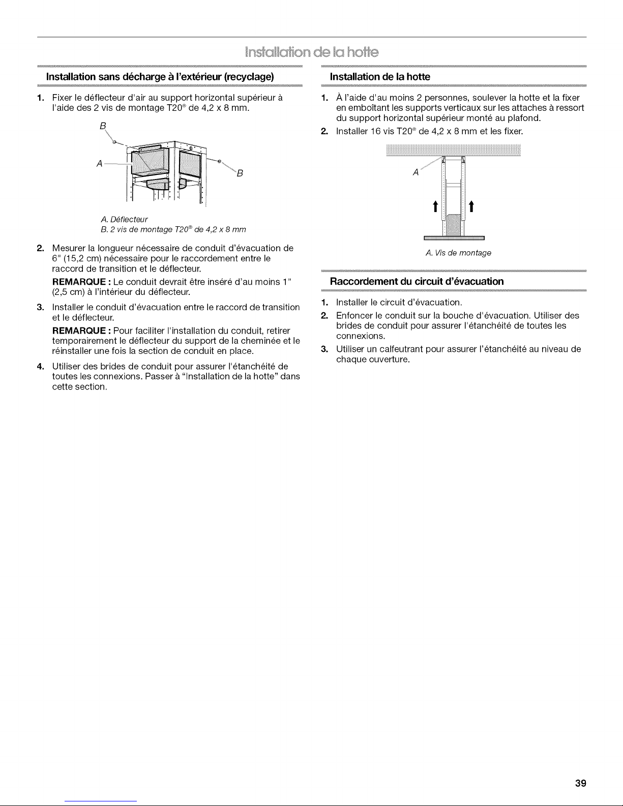
Installation sans d_charge & I'ext_rieur (recyclage)
Installation de la hotte
1. Fixer le deflecteur d'air au support horizontal superieur
I'aide des 2 vis de montage T20 ®de 4,2 x 8 mm.
B
A. D#flecteur
B. 2 vis de montage T20®de 4,2 x 8 mm
2. Mesurer la Iongueur necessaire de conduit d'evacuation de
6" (15,2 cm) necessaire pour le raccordement entre le
raccord de transition et le deflecteur.
REMARQUE : Le conduit devrait _tre inser6 d'au moins 1"
(2,5 cm) & I'interieur du deflecteur.
3. Installer le conduit d'evacuation entre le raccord de transition
et le deflecteur.
REMARQUE : Pour faciliter I'installation du conduit, retirer
temporairement le deflecteur du support de la cheminee et le
reinstaller une fois la section de conduit en place.
4. Utiliser des brides de conduit pour assurer I'etanch6it6 de
toutes les connexions. Passer & "Installation de la hotte" dans
cette section.
1. /_,I'aide d'au moins 2 personnes, soulever la hotte et la fixer
en emboitant les supports verticaux sur les attaches &ressort
du support horizontal superieur monte au plafond.
2. Installer 16 vis T20 ®de 4,2 x 8 mm et les fixer.
A
! !
A. Vis de montage
Raccordement du circuit d'_vacuation
1. Installer le circuit d'evacuation.
2. Enfoncer le conduit sur la bouche d'evacuation. Utiliser des
brides de conduit pour assurer I'etancheite de toutes les
connexions.
3. Utiliser un calfeutrant pour assurer I'etancheite au niveau de
chaque ouverture.
39
Page 40
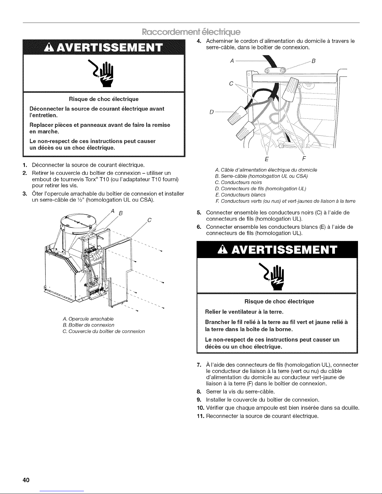
CCO t} seme :f elect/" que
Risque de choc _lectrique
D_connecter la source de courant _lectrique avant
rentretien.
Replacer pi_ces et panneaux avant de faire la remise
en marche.
Le non=respect de ces instructions peut causer
un d_c_s ou un choc _lectrique.
1. Deconnecter la source de courant electrique.
2. Retirer le couvercle du boitier de connexion - utiliser un
embout de tournevis Torx®T10 (ou I'adaptateur T10 fourni)
pour retirer les vis.
3. Oter I'opercule arrachable du boitier de connexion et installer
un serre-c&ble de 1/2"(homologation UL ou CSA).
4. Acheminer le cordon d'alimentation du domicile & travers le
serre-c&ble, dans le boitier de connexion.
i
E F
A. Cbble d'alimentation #lectrique du domicile
B. Serre-cbble (homologation UL ou CSA)
C. Conducteurs noirs
D. Connecteurs de ills (homologation UL)
E. Conducteurs blancs
F. Conducteurs verts (ou nus) et vert-jaunes de fiaison a la terre
_'_' ,,/A B
// / C
l "
A. Opercule arrachable
B. BoTtier de connexion
C. Couvercle du boTtier de connexion
5. Connecter ensemble les conducteurs noirs (C) & I'aide de
connecteurs de fils (homologation UL).
6. Connecter ensemble les conducteurs blancs (E)& I'aide de
connecteurs de fils (homologation UL).
Risque de choc _lectrique
Relier le ventilateur a la terre.
Brancher le fil reli_ a la terre au fil vertet jaune reli_
la terre darts la boite de la borne.
Le non=respect de ces instructions peut causer un
d_c_s ou un choc 61ectrique.
7. A I'aide des connecteurs de fils (homologation UL), connecter
le conducteur de liaison & la terre (vert ou nu) du c&ble
d'alimentation du domicile au conducteur vert-jaune de
liaison & la terre (F) dans le boitier de connexion.
8. Serrer la vis du serre-c&ble.
9. Installer le couvercle du boitier de connexion.
10. Verifier que chaque ampoule est bien inser6e dans sa douille.
11. Reconnecter la source de courant electrique.
40
Page 41
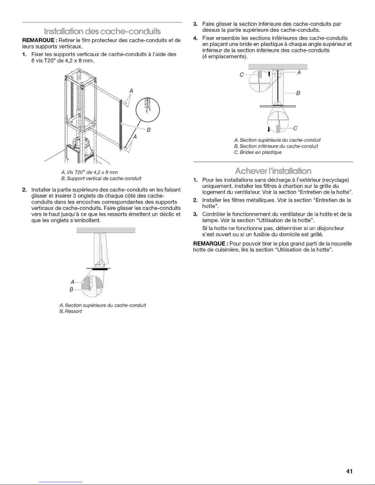
REMARQUE : Retirer le film protecteur des cache-conduits et de
leurs supports verticaux.
1. Fixer les supports verticaux de cache-conduits & I'aide des
8 vis T20®de 4,2 x 8 mm.
A
A. Vis T20 ®de 4,2 x 8 mm
B. Support vertical de cache-conduit
2.
Installer lapartie superieure des cache-conduits en les faisant
glisser et inserer 3 onglets de chaque c6te des cache-
conduits dans les encoches correspondantes des supports
verticaux de cache-conduits. Faire glisser les cache-conduits
vers le haut jusqu'& ce que les ressorts emettent un declic et
que les onglets s'emboftent.
"I
3.
Faire glisser la section inferieure des cache-conduits par
dessus la partie superieure des cache-conduits.
4.
Fixer ensemble les sections inferieures des cache-conduits
en plagant une bride en plastique &chaque angle superieur et
inferieur de la section inferieure des cache-conduits
(4 emplacements).
A. Section sup#rieure du cache-conduit
B. Section inf#rieure du cache-conduit
C. Brides en plastique
1. Pour les installations sans d@charge a I"ext@rieur (recyclage)
uniquement, installer les filtres a charbon sur la grille du
Iogement du ventilateur. Voir la section "Entretien de la hotte".
2. Installer les filtres metalliques. Voir la section "Entretien de la
hotte".
3. Contr61er le fonctionnement du ventilateur de la hotte et de la
lampe. Voir la section "Utilisation de la hotte".
Si la hotte ne fonctionne pas, determiner si un disjoncteur
s'est ouvert ou si un fusible du domicile est grill&
REMARQUE : Pour pouvoir tirer le plus grand parti de la nouvelle
hotte de cuisiniere, lire la section "Utilisation de la hotte".
A. Section sup#rieure du cache-conduit
B. Ressort
41
Page 42
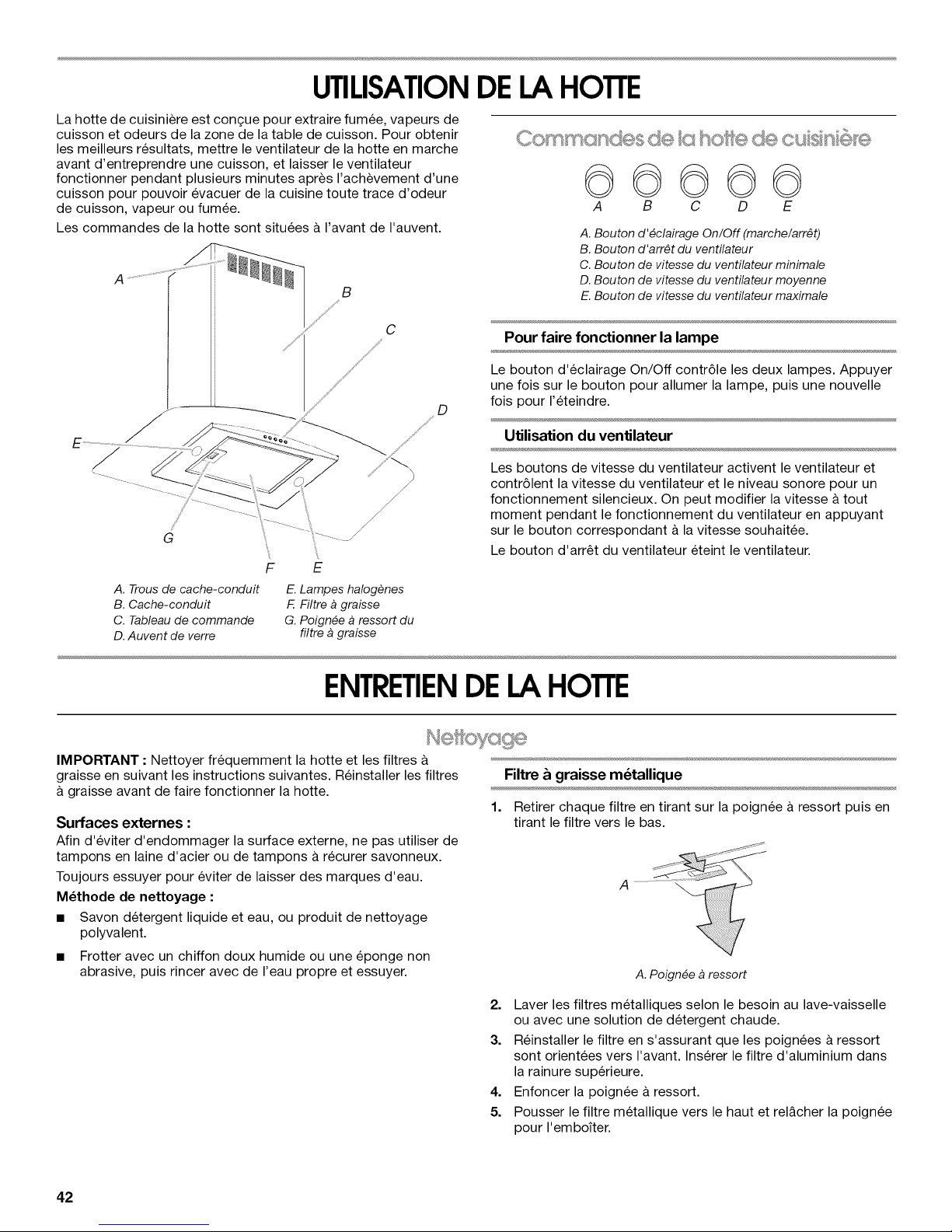
UTILISATIONDELAHOTTE
La hotte de cuisiniere est congue pour extraire fumee, vapeurs de
cuisson et odeurs de la zone de la table de cuisson. Pour obtenir
les meilleurs resultats, mettre le ventilateur de la hotte en marche
avant d'entreprendre une cuisson, et laisser le ventilateur
fonctionner pendant plusieurs minutes apres I'achevement d'une
cuisson pour pouvoir evacuer de la cuisine toute trace d'odeur
de cuisson, vapeur ou fumee.
Les commandes de la hotte sont situees a I'avant de I'auvent.
E
A. Trous de cache-conduit
B. Cache-conduit
C. Tableau de commande
D.Auvent de verre
E.Lampes halogenes
F. Filtre a graisse
G. Poign#e a ressort du
filtre a graisse
©©©©©
A B C D E
A. Bouton d'#clairage On/Off (marche/arr#t)
B. Bouton d'arr#t du ventilateur
C. Bouton de vitesse du ventilateur minimale
D.Bouton de vitesse du ventilateur moyenne
E.Bouton de vitesse du ventilateur maximale
Pour faire fonctionner la lampe
Le bouton d'eclairage On/Off contr61e les deux lampes. Appuyer
une fois sur le bouton pour allumer la lampe, puis une nouvelle
fois pour I'eteindre.
Utilisation du ventilateur
Les boutons de vitesse du ventilateur activent le ventilateur et
contr61ent la vitesse du ventilateur et le niveau sonore pour un
fonctionnement silencieux. On peut modifier la vitesse & tout
moment pendant le fonctionnement du ventilateur en appuyant
sur le bouton correspondant & la vitesse souhaitee.
Le bouton d'arr_t du ventilateur eteint le ventilateur.
ENTRETIENDELAHOTTE
IMPORTANT : Nettoyer frequemment la hotte et les filtres &
graisse en suivant les instructions suivantes. Reinstaller les filtres
&graisse avant de faire fonctionner la hotte.
Surfaces externes :
Afin d'eviter d'endommager la surface externe, ne pas utiliser de
tampons en laine d'acier ou de tampons & recurer savonneux.
Toujours essuyer pour eviter de laisser des marques d'eau.
M_thode de nettoyage :
• Savon detergent liquide et eau, ou produit de nettoyage
polyvalent.
• Frotter avec un chiffon doux humide ou une eponge non
abrasive, puis rincer avec de I'eau propre et essuyer.
Filtre & graisse m_tallique
1.
Retirer chaque filtre en tirant sur la poignee & ressort puis en
tirant le filtre vers le bas.
2. Laver les filtres metalliques selon le besoin au lave-vaisselle
ou avec une solution de detergent chaude.
3. Reinstaller le filtre en s'assurant que les poignees & ressort
sont orientees vers I'avant. Inserer le filtre d'aluminium dans
la rainure superieure.
4. Enfoncer la poignee &ressort.
5. Pousser le filtre metallique vers le haut et rel&cher la poignee
pour I'emboiter.
42
Page 43

Filtresd'installationsansd_charge&I'ext_rieur
(recyclage)
Le filtre & charbon n'est pas lavable. Celui-ci devrait durer
pendant 6 mois dans des conditions d'utilisation normales.
Remplacer par I'ensemble de filtre a charbon numero
W10412939.
Remplacement du filtre a charbon :
1. Retirer le filtre & graisse metallique de la hotte. Voir "Filtre
graisse metallique" dans cette section.
2. Deplier les attaches a ressort pour les ecarter du filtre
graisse metallique.
3. Placer le filtre a charbon dans la partie superieure du filtre
metallique.
4. Replier les attaches & ressort pour les remettre en place afin
de fixer lefiltre a charbon au filtre metallique.
Remplacement d'une lampe & halog_ne
Interrompre I'alimentation de la hotte; attendre le refroidissement
de la lampe & halogene. Pour eviter d'endommager ou de reduire
la Iongevite de I'ampoule neuve, ne pas toucher I'ampoule avec
les doigts nus. Remplacer I'ampoule en la manipulant avec un
mouchoir de papier ou des gants de coton.
Si les nouvelles lampes ne fonctionnent pas, verifier que chaque
lampe est correctement inseree dans sa douille avant de
demander I'intervention d'un depanneur.
1. Deconnecter la source de courant electrique.
2. A I'aide d'un tournevis & lame plate, degager le protege-
ampoule avec precaution.
3. Enlever la lampe. Installer une lampe & halogene neuve de
120 V/40 W maximum, & culot de type G-9.
4. Reinstaller le protege-ampoule.
5. Reconnecter la source de courant electrique.
5. Reinstaller le filtre a graisse metallique. Voir "Filtre a graisse
metallique" dans cette section.
43
Page 44
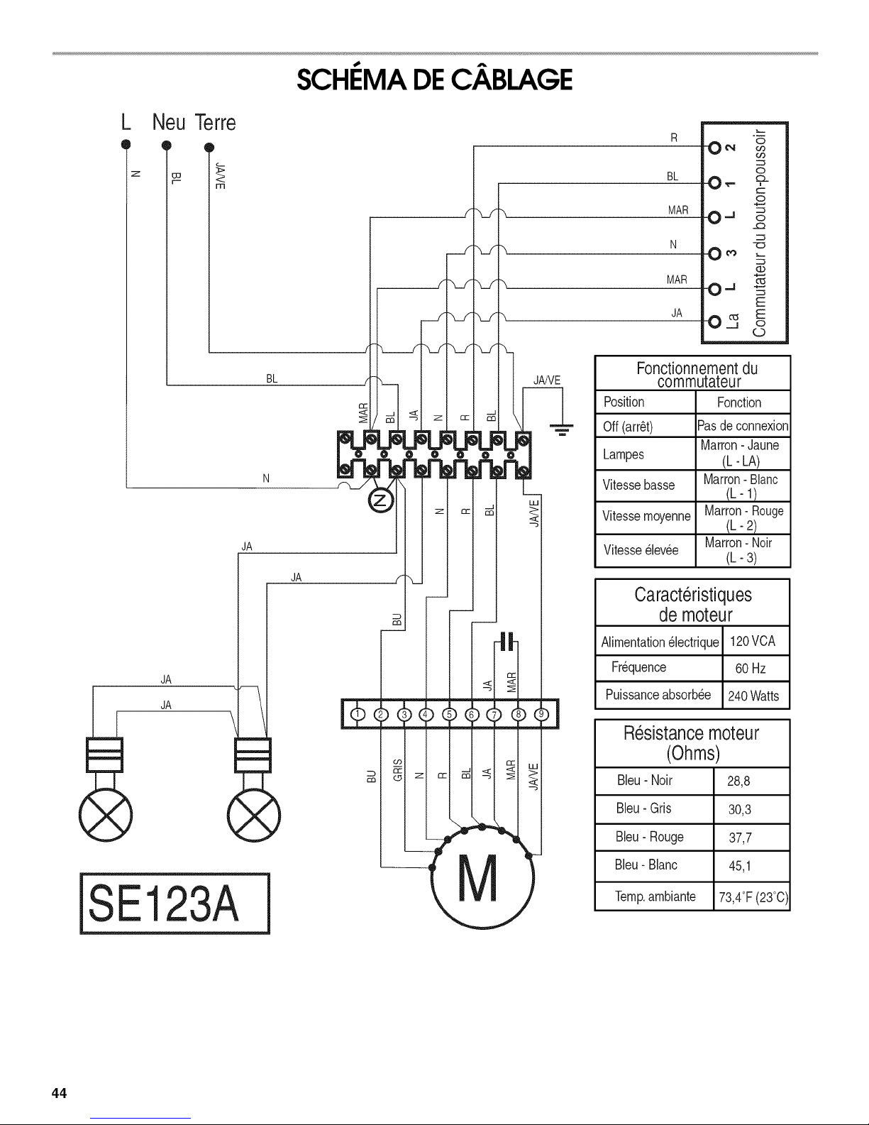
SCHI MA DEC ,BLAGE
L Neu Terre
_tc_ -
z _
3>
m
JA
BL
JA
x_.f
x_f
"x._f
co
V
JANE
[
R ON _
BL O_
MARO. J
N -o
MAR
JA O_ Eo
Fonctionnementdu
commutateur
Position
Off(arr_t)
Lampes
Vitessebasse
Vitessemoyenne
Vitesse_levee
Caracteristiques
de moteur
.m
0
t.-
0 _ _-
0-_ _
E
o
Fonction
Pasdeconnexion
Marron-Jaune
(h- LA)
Marron- Blanc
¢-1)
Marron-Rouge
¢-2)
Marron- Noir
(h-3)
JA
JA
SE123A
Alimentation_lectrique 120VCA
Fr_quence 60Hz
Puissanceabsorbee 240Watts
Resistancemoteur
(Ohms)
Bleu- Noir 28,8
Bleu- Gris 30,3
)
Bleu- Rouge 37,7
Bleu- Blanc 45,1
Temp.ambiante 73,4°F(23°0)
44
Page 45
ASSISTANCEOU SERVICE
Avant de faire un appel pour assistance ou service, determiner si
un disjoncteur s'est ouvert ou si un fusible du domicile est grill&
Ce guide peut vous faire economiser le coQt d'une visite de
service. Si vous avez encore besoin d'aide, suivre les instructions
ci-dessous.
Lors d'un appel, veuillez connaitre la date d'achat, le numero de
modele et le numero de serie au complet de I'appareil. Ces
renseignements nous aideront & mieux repondre a votre
demande.
Si vous avez besoin de pi_ces de rechange
Si vous avez besoin de commander des pieces de rechange,
nous vous recommandons d'employer uniquement des pieces
specifiees par I'usine. Les pieces specifiees par I'usine
conviendront et fonctionneront bien parce qu'elles sont
fabriquees avec la m_me precision utilisee dans la fabrication de
chaque nouvel appareil IKEA®.
Pour Iocaliser des pieces specifiees par I'usine dans votre region,
nous appeler ou telephoner au centre de service designe le plus
proche.
Veuillez appelersansfraisleCentrepourrexp6r_encede la
clientele de WhirlpoolCanadaLPau: 1-866-664-2449.
Nos consultants vous renseigneront sur les sujets suivants :
• Caracteristiques et specifications sur toute notre gamme
d'appareils electromenagers.
• Consignes d'utilisation et d'entretien.
• Vente d'accessoires et de pieces de rechange.
References aux marchands Iocaux, aux distributeurs de
pieces de rechange et aux compagnies de service. Les
techniciens de service designes par Whirlpool Canada LP
sont formes pour remplir la garantie des produits et fournir un
service apres la garantie, partout au Canada.
Pour plus d'assistance
Si vous avez besoin de plus d'assistance, vous pouvez
soumettre par ecrit toute question ou preoccupation & Whirlpool
Canada LP a I'adresse suivante :
Centre pour I'eXperience de la clientele
Whirlpool Canada LP
200 - 6750 Century Ave.
Mississauga, Ontario L5N 0B7
Veuillez inclure dans votre correspondance un numero de
telephone oQ on peut vous joindre dans la journee.
Ensemble Filtre & charbon
(pour installations sans decharge a I'exterieur uniquement)
Commander la piece numero W10412939
Ensemble d'extension de chemin_e
Commander lapiece numero W10272078
Ensemble d'air de compensation de 6" (15,2 cm)
(consulter le code du b&timent local)
Commander la piece numero W10446915
45
Page 46
GARANTIEDESGROS APPAREILSMENAGERSIKEA
Pendant combien de temps la garantie limitde IKEA est-elle valide?
Cette garantie limitee est valide pendant cinq ans a compter de la date d'achat Iorsque ce gros appareil menager a et6 utilise et
entretenu conformement aux instructions jointes au produit ou fournies avec celui-ci, sauf si I'appareil porte le nom LAGAN, auquel cas
cette garantie limitee est valide pendant un an & compter de la date d'achat. Cette garantie limitee est valide uniquement aux Etats-
Unis ou au Canada et s'applique exclusivement Iorsque le gros appareil menager est utilise dans le pays oQ il a et6 achet& Une preuve
de la date d'achat d'origine est exigee pour obtenir un service dans le cadre de la presente garantie limitee.
Quels sont les appareils mdnagers non couverts par la garantie limitde IKEA de cinq (5) ans?
Pour les gros appareils menagers portant le nom "LAGAN", cette garantie limitee est valide pendant un an &compter de la date
d'achat.
Qui effectuera I'intervention d'entretien ou de rdparation?
Cette garantie limitee est fournie par Whirlpool Corporation ou Whirlpool Canada LP (ci-apres designees "Whirlpool"). Le service doit
etre fourni par une compagnie de service designee par Whirlpool.
Que couvre cette garantie limitde?
La garantie limitee paiera pour les pieces specifiees par I'usine et la main-d'ceuvre pour corriger les vices de materiaux ou de
fabrication qui existaient dej& Iorsque ce gros appareil menager a ete achet& Les exceptions figurent sous le titre "Quels sont les
elements non couverts par cette garantie limitee?".
Quelles mesures seront prises pour corriger le probl_me?
La compagnie de service designee examinera le produit et decidera, & sa seule discretion, si ce produit est couvert par cette garantie
limitee. S'il est considere comme couvert, la compagnie de service designee corrigera le defaut. Le seul et exclusif recours du client
dans le cadre de la presente garantie limitee consiste en la reparation du produit telle que mentionne dans la presente.
Quels sont les dldments non couverts par cette garantie limitde?
• Les visites de service pour rectifier I'installation du gros appareil menager, montrer a I'utilisateur comment utiliser le gros appareil
menager, remplacer ou reparer des fusibles du domicile ou rectifier le c&blage ou la plomberie du domicile.
• Les visites de service pour reparer ou remplacer les ampoules electriques, les filtres & air ou les filtres & eau de I'appareil. Les pieces
consomptibles ne sont pas couvertes par la garantie.
• Les pieces de rechange ou la main-d'ceuvre Iorsque ce gros appareil menager est utilise & des fins autres que I'usage domestique
unifamilial normal ou Iorsque les instructions d'installation et/ou les instructions de I'operateur ou de I'utilisateur fournies ne sont pas
respectees.
• Les dommages imputables & : accident, modification, usage impropre ou abusif, incendie, inondation, actes de Dieu, installation
fautive ou installation non conforme aux codes d'electricite ou de plomberie ou I'utilisation de pieces consomptibles ou de produits
de nettoyage dont I'utilisation n'est pas approuvee.
• Les defauts d'apparence, notamment les eraflures, traces de choc, fissures ou tout autre dommage subi par le fini du gros appareil
menager, &moins que ces dommages ne resultent de vices de materiaux ou de fabrication et ne soient signales dans les 30 jours qui
suivent la date d'achat.
• Toute perte d'aliments ou de medicaments due &une defaillance du refrigerateur ou du congelateur.
• L'enlevement et la livraison. Ce gros appareil menager est con£_upour etre repare & domicile.
• Les reparations aux pieces ou systemes resultant d'une modification non autorisee faite &I'appareil.
• Les frais de deplacement et de transport pour une intervention sur un produit si le gros appareil menager est situe dans une region
eloignee oQ un service d'entretien autorise n'est pas disponible.
• L'enlevement et la reinstallation du gros appareil menager si celui-ci est installe dans un endroit inaccessible ou n'est pas installe
conformement aux instructions d'installation fournies.
• Les pieces de rechange ou la main-d'ceuvre pour les gros appareils menagers dont les numeros de modele/de serie ont ete enleves,
modifies ou ne peuvent pas etre facilement identifies.
Le coQt d'une r_paration ou de pi_ces de rechange dans le cadre de ces circonstances exclues est a la charge du client.
Clause d'exondration de responsabilit_ au titre des garanties imPlicites
LES GARANTIES IMPLICITES, Y COMPRIS LES GARANTIES APPLICABLES DE QUALITE MARCHANDE OU D'APTITUDE A UN
USAGE PARTIC.ULIER, SONT LIMIT¢:ES A CINQ ANS (U.NAN POUR LES GROS APPAREILS M¢:NAGERS PORTANT LE NOM
"LAGAN") OU A LA PLUS COURTE P¢:RIODE AUTORISEE PAR LA LOI. Certains €:tats et provinces ne permettent pas de limitation sur
la duree de garanties implicites de qualite marchande ou d'aptitude &un usage particulier, de sorte que la limitation ci-dessus peut ne
pas etre applicable dans votre cas. Cette garantie vous confere des droits juridiques specifiques et vous pouvez egalement jouir
d'autres droits qui peuvent varier d'une juridiction & I'autre.
Limitation des recours; exclusion des dommages fortuits et indirects
LE SEUL ET EXCLUSIF RECOURS DU CLIENT DANS LE CADRE DE LA PR¢:SENTE GARANTIE LIMIT¢:E CONSISTE EN LA
R¢:PARATION PR¢:VUE CI-DESSUS. WHIRLPOOL N'ASSUME AUCUNE RESPONSABILIT¢: POUR LES DOMMAGES FORTUITS OU
INDIRECTS. Certains €:tats et certaines provinces ne permettent pas I'exclusion ou la limitation des dommages fortuits ou indirects de
sorte que ces limitations et exclusions peuvent ne pas etre applicables dans votre cas. Cette garantie vous confere des droits juridiques
specifiques et vous pouvez egalement jouir d'autres droits qui peuvent varier d'une juridiction & I'autre.
46
Page 47
Comment nous contacter si vous avez besoin d'une intervention d'entretien ou de rdparation
Si vous residez & I'exterieur des 50 12tatsdes 12tats-Unis et du Canada, contactez votre marchand IKEA autorise pour determiner si une
autre garantie s'applique.
Si vous avez besoin d'une intervention d'entretien ou de reparation, veuillez lire les Instructions d'installation et/ou la section
"Depannage" dans le Guide d'utilisation et d'entretien avant de nous contacter. Si vous avez besoin d'aide supplementaire, n'hesitez
pas a nous contacter aux 12tats-Unis et au Canada au 1-866-664-2449. 3/09
Conservez ce manuel et votre re£u de vente ensemble pour
r_f_rence ult_rieure. Pour le service sous garantie, vous
devez presenter un document prouvant la date d'achat ou
d'installation.
Inscrivez les renseignements suivants au sujet de votre gros
appareil menager pour mieux vous aider a obtenir assistance ou
service en cas de besoin. Vous devrez connaitre le numero de
modele et le numero de serie au complet. Vous trouverez ces
renseignements sur la plaque signaletique situ6e sur le produit.
Nom du marchand
Adresse
Num_ro de t_l_phone
Num_ro de module
Num_ro de s_rie
Date d'achat
47
Page 48

W10502581D
© 2012.
All rights reserved.
Todos los derechos reservados.
Tous droits reserves.
® IKEA is a registered trademark of Inter-lkea Systems B.V.
® IKEA es una marca registrada de Inter-lkea Systems B.V.
® IKEA est une marque deposee de Inter-lkea Systems B.V.
Printed in Mexico
Impreso en Mexico
Imprime au Mexique
12/12
 Loading...