

Page 1
|KEA ®
30" (76.2 CM) VENTEDRANGE HOOD
HOTTED'ASPIRATIONDE30" (76,2 CM)
Table of Contents/Table des matieres ............................................................................. 2
iMPORTANT: READ AND SAVETHESE iNSTRUCTiONS.
FOR RESiDENTiAL USE ONLY.
iMPORTANT : LIRE ET CONSERVER CES iNSTRUCTiONS.
POUR UTJUSATJON RESIDENTIELLE UNIQUEMENT.
99044501 A/W10258591A
Page 2
TABLEOF CONTENTS
TABLEDESMATIERES
RANGE HOOD SAFETY ................................................................. 2
INSTALLATION REQUIREMENTS ................................................ 4
Tools and Parts ............................................................................ 4
Location Requirements ................................................................ 4
Venting Requirements .................................................................. 5
Electrical Requirements ............................................................... 6
INSTALLATION INSTRUCTIONS .................................................. 7
Prepare Location .......................................................................... 7
Install Range Hood ....................................................................... 8
Make Electrical Connection ......................................................... 9
Complete Installation ................................................................... 9
RANGE HOOD USE ...................................................................... 10
Range Hood Controls ................................................................ 10
RANGE HOOD CARE ................................................................... 10
Cleaning ...................................................................................... 10
ASSISTANCE OR SERVICE ......................................................... 11
In the U.S.A................................................................................ 11
In Canada ................................................................................... 11
WARRANTY .................................................................................. 11
SECURITE DE LA HOTTE DE CUlSINIERE ............................... 13
EXIGENCES D'INSTALLATION ................................................... 15
Outillage et pieces ...................................................................... 15
Exigences d'emplacement ......................................................... 15
Exigences concernant I'evacuation ........................................... 16
Specifications electriques .......................................................... 17
INSTRUCTIONS D'INSTALLATION ............................................. 18
Preparation de I'emplacement ................................................... 18
Installation de la hotte ................................................................ 19
Raccordement electrique ........................................................... 20
Achever I'installation .................................................................. 20
UTILISATION DE LA HOTTE DE CUlSINIF:RE ........................... 21
Commandes de la hotte de cuisiniere ....................................... 21
ENTRETIEN DE LA Ho'n'E .......................................................... 21
Nettoyage ................................................................................... 21
ASSISTANCE OU SERVICE ......................................................... 22
GARANTIE ..................................................................................... 23
RANGE HOOD SAFETY
Your safety and the safety of others are very important.
We have provided many important safety messages in this manual and on your appliance. Always read and obey all safety
messages.
This is the safety alert symbol.
This symbol alerts you to potential hazards that can kill or hurt you and others.
All safety messages will follow the safety alert symbol and either the word "DANGER" or "WARNING."
These words mean:
You can be killed or seriously injured if you don't immediately
follow instructions.
You can be killed or seriously injured if you don't follow
instructions.
All safety messages will tell you what the potential hazard is, tell you how to reduce the chance of injury, and tell you what can
happen if the instructions are not followed.
2
Page 3
iMPORTANT SAFETY iNSTRUCTiONS
WARNING: TO REDUCE THE RISK OF FIRE, ELECTRIC
SHOCK, OR INJURY TO PERSONS, OBSERVE THE
FOLLOWING:
[] Use this unit only in the manner intended by the
manufacturer. If you have questions, contact the
manufacturer.
[] Before servicing or cleaning the unit, switch power off at
service panel and lock the service disconnecting means to
prevent power from being switched on accidentally. When
the service disconnecting means cannot be locked,
securely fasten a prominent warning device, such as a tag,
to the service panel.
[] Installation work and electrical wiring must be done by
qualified person(s) in accordance with all applicable codes
and standards, including fire-rated construction.
[] Sufficient air is needed for proper combustion and
exhausting of gases through the flue (chimney) of fuel
burning equipment to prevent backdrafting. Follow the
heating equipment manufacturer's guideline and safety
standards such as those published by the National Fire
Protection Association (NFPA), the American Society for
Heating, Refrigeration and Air Conditioning Engineers
(ASHRAE), and the local code authorities.
[] When cutting or drilling into wall or ceiling; do not damage
electrical wiring and other utilities.
[] Ducted fans must always be vented outdoors.
CAUTION: For general ventilating use only. Do not use
to exhaust hazardous or explosive materials and vapors.
CAUTION: To reduce risk of fire and to properly exhaust
air, be sure to duct air outside - do not vent exhaust air into
spaces within walls or ceilings, attics or into crawl spaces,
or garages.
WARNING: TO REDUCE THE RISK OF FIRE, USE ONLY
METAL DUCTWORK.
WARNING: TO REDUCE THE RISK OF A RANGE TOP
GREASE FIRE:
[] Never leave surface units unattended at high settings.
Boilovers cause smoking and greasy spillovers that may
ignite. Heat oils slowly on low or medium settings.
[] Always turn hood ON when cooking at high heat or when
flambeing food (i.e. Crepes Suzette, Cherries Jubilee,
Peppercorn Beef Flamb6).
[] Clean ventilating fans frequently. Grease should not be
allowed to accumulate on fan or filter.
[] Use proper pan size. Always use cookware appropriate for
the size of the surface element.
WARNING: TO REDUCE THE RISK OF INJURY TO
PERSONS IN THE EVENT OF A RANGE TOP GREASE
FIRE, OBSERVE THE FOLLOWING: a
[] SMOTHER FLAMES with a close fitting lid, cookie sheet, or
metal tray, then turn off the burner. BE CAREFUL TO
PREVENT BURNS. If the flames do not go out
immediately, EVACUATE AND CALL THE FIRE
DEPARTMENT.
[] NEVER PICK UP A FLAMING PAN - you may be burned.
[] DO NOT USE WATER, including wet dishcloths or towels -
a violent steam explosion will result.
[] Use an extinguisher ONLY if:
- You know you have a class ABC extinguisher, and you
already know how to operate it.
- The fire is small and contained in the area where it
started.
- The fire department is being called.
- You can fight the fire with your back to an exit.
aBased on "Kitchen Fire Safety Tips" published by NFPA.
[] WARNING: To reduce the risk of fire or electrical shock,
do not use this fan with any solid-state speed control
device.
SAVE THESE iNSTRUCTiONS
Page 4
INSTALLATIONREQUIREMENTS
Gather the required tools and parts before starting installation.
Read and follow the instructions provided with any tools listed
here.
Tools needed
• Level
• Drill
• 1V4"drill bit
• 1/8"(3 ram) drill bit for pilot holes
• Pencil
• Pliers
• Wire stripper or utility knife
• Tape measure or ruler
• Caulking gun and weatherproof caulking compound
• Phillips screwdriver
• Saber or keyhole saw
• Vent clamps
• Metal snips
• Compass or 7" (17.8 cm) circle template
Parts supplied
Check that all parts are included.
• Literature package (1)
• Hardware package (1)
• 7" (17.8 cm) round damper
IMPORTANT." Observe all governing codes and ordinances.
• It is the installer's responsibility to comply with installation
clearances specified on the model/serial rating plate. The
model/serial rating plate is located inside the range hood on
the rear wall.
• Range hood location should be away from strong draft areas,
such as windows, doors and strong heating vents.
• Cabinet opening dimensions that are shown must be used.
Given dimensions provide minimum clearance. Consult the
cooktop/range manufacturer installation instructions before
making any cutouts.
• Grounded electrical outlet is required. See "Electrical
Requirements" section.
• The range hood is factory set for venting through the roof or
wall.
• All openings in ceiling and wall where range hood will be
installed must be sealed.
For Mobile Home Installations
The installation of this range hood must conform to the
Manufactured Home Construction Safety Standards, Title 24
CFR, Part 328 (formerly the Federal Standard for Mobile Home
Construction and Safety, Title 24, HUD, Part 280) or when such
standard is not applicable, the standard for Manufactured Home
Installation 1982 (Manufactured Home Sites, Communities and
Setups) ANSI A225.1/NFPA 501A*, or latest edition, or with local
codes.
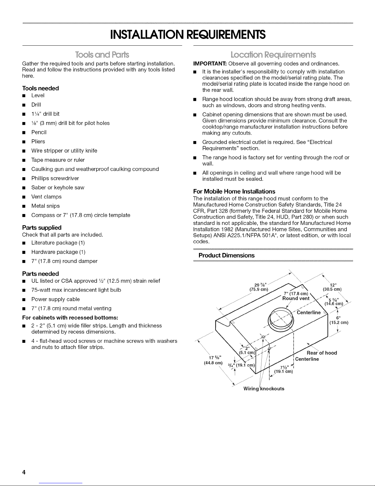
Product Dimensions
Parts needed
• UL listed or CSA approved 1/2"(12.5 mm) strain relief
• 75-watt max incandescent light bulb
• Power supply cable
• 7" (17.8 cm) round metal venting
For cabinets with recessed bottoms:
• 2 - 2" (5.1 cm) wide filler strips. Length and thickness
determined by recess dimensions.
• 4 - flat-head wood screws or machine screws with washers
and nuts to attach filler strips.
29 7/8" _ 12"
(75.9 crn) (30.5 cm)
4
(15.2 cm)
Centerline
7W' _ii
i (19.1 cm)
:nockouts
Page 5
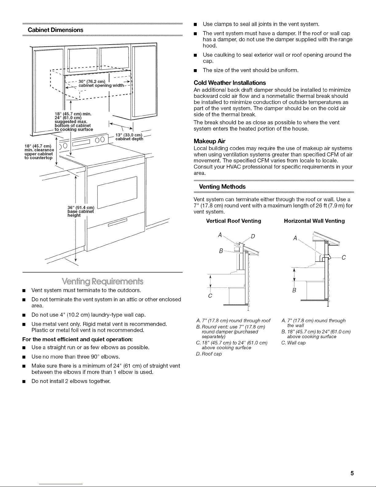
Cabinet Dimensions
I
I
t
18" (45.7 cra) rain.
24" (61.0 era)
suggested max.
bottom of cabinet
cooking surface
Use clamps to seal all joints in the vent system.
The vent system must have a damper. If the roof or wall cap
has a damper, do not use the damper supplied with the range
hood.
• Use caulking to seal exterior wall or roof opening around the
cap.
• The size of the vent should be uniform.
Cold Weather Installations
An additional back draft damper should be installed to minimize
backward cold air flow and a nonmetallic thermal break should
be installed to minimize conduction of outside temperatures as
part of the vent system. The damper should be on the cold air
side of the thermal break.
The break should be as close as possible to where the vent
system enters the heated portion of the house.
18" (45.7 era)
rain. cJearanse
upper cabinet
to countertop
36" (91.4 era)
base cabinet
height
• Vent system must terminate to the outdoors.
• Do not terminate the vent system in an attic or other enclosed
area.
• Do not use 4" (10.2 cm) laundry-type wall cap.
• Use metal vent only. Rigid metal vent is recommended.
Plastic or metal foil vent is not recommended.
For the most efficient and quiet operation:
• Use a straight run or as few elbows as possible.
• Use no more than three 90 ° elbows.
• Make sure there is a minimum of 24" (61 cm) of straight vent
between the elbows if more than 1 elbow is used.
• Do not install 2 elbows together.
Makeup Air
Local building codes may require the use of makeup air systems
when using ventilation systems greater than specified CFM of air
movement. The specified CFM varies from locale to locale.
Consult your HVAC professional for specific requirements in your
area.
Venting Methods
Vent system can terminate either through the roof or wall. Use a
7" (17.8 cm) round vent with a maximum length of 26 ft (7.9 m) for
vent system.
Vertical Roof Venting Horizontal Wall Venting
A D A
_ ..................................C
.............:::::....................
i
B
C
A. 7" (17.8 cm) round through roof
B. Round vent: use 7" (17.8 cm)
round damper (purchased
separately)
C. 18" (45.7cm) to 24" (61.0 cm)
above cooking surface
D. Roof cap
A. 7" (17.8 cm) round through
the wall
B. 18" (45. Tcm) to 24" (61.0 cm)
above cooking surface
C. Waft cap
Page 6
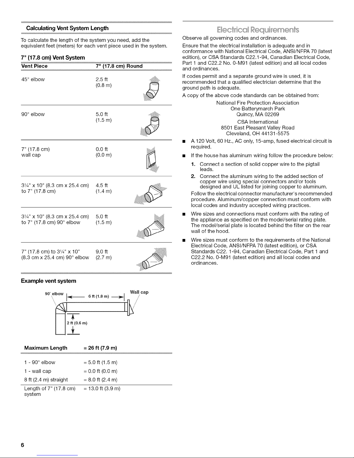
Calculating Vent System Length
Tocalculate the length of the system you need, addthe
equivalent feet (meters)for each vent piece used in the system.
7" (17.8 cm) Vent System
Vent Piece 7"(17.8 cm) Round
45° elbow 2.5 ft
(0.8m)
90° elbow 5.0 ft
(1.5m)
7" (17.8 cm) 0.0 ft
wall cap (0.0 m)
31/4"x 10" (8.3 cm x 25.4 cm) 4.5 ft
to 7" (17.8 cm) (1.4 m)
31/4"x 10" (8.3 cm x 25.4 cm) 5.0 ft
to 7" (17.8 cm) 90° elbow (1.5 m)
7" (17.8 cm) to 31/4"x 10" 9.0 ft
(8.3 cm x 25.4 cm) 90 ° elbow (2.7 m)
& equ s
Observe all governing codes and ordinances.
Ensure that the electrical installation is adequate and in
conformance with National Electrical Code, ANSl/NFPA 70 (latest
edition), or CSA Standards C22.1-94, Canadian Electrical Code,
Part 1 and C22.2 No. 0-M91 (latest edition) and all local codes
and ordinances.
If codes permit and a separate ground wire is used, it is
recommended that a qualified electrician determine that the
ground path is adequate.
A copy of the above code standards can be obtained from:
National Fire Protection Association
One Batterymarch Park
Quincy, MA 02269
CSA International
8501 East Pleasant Valley Road
Cleveland, OH 44131-5575
• A 120 Volt, 60 Hz., AC only, 15-amp, fused electrical circuit is
required.
• If the house has aluminum wiring follow the procedure below:
1. Connect a section of solid copper wire to the pigtail
leads.
2. Connect the aluminum wiring to the added section of
copper wire using special connectors and/or tools
designed and UL listed for joining copper to aluminum.
Follow the electrical connector manufacturer's recommended
procedure. Aluminum/copper connection must conform with
local codes and industry accepted wiring practices.
• Wire sizes and connections must conform with the rating of
the appliance as specified on the model/serial rating plate.
The model/serial plate is located behind the filter on the rear
wall of the hood.
Wire sizes must conform to the requirements of the National
Electrical Code, ANSl/NFPA 70 (latest edition), or CSA
Standards C22.1-94, Canadian Electrical Code, Part 1 and
C22.2 No. 0-M91 (latest edition) and all local codes and
ordinances.
Example vent system
90° elbow
6 ft (1.8 m) "''''"-_1
-T
Maximum Length = 26 ft (7.9 m)
1 - 90° elbow
1 - wall cap
8 ft (2.4 m) straight
Length of 7" (17.8 cm)
system
6
= 5.0 ft (1.5 m)
= 0.0 ft (0.0 m)
= 8.0 ft (2.4 m)
= 13.0 ft (3.9 m)
Wall cap
Page 7
INSTALLATIONINSTRUCTIONS
It is recommended that the vent system be installed before
hood is installed. Determine Wiring Hole Location
• Before making cutouts, make sure there is proper clearance
within the ceiling or wall for exhaust vent.
• Check your ceiling height and the hood height maximum
before you select your hood.
• To avoid damage or dirt, place a thick, heavy covering over
countertop, cooktop, or range.
1. Disconnect power.
2. Determine which venting method to use: roof or wall.
3. Select a flat surface for assembling the range hood. Place
covering over that surface.
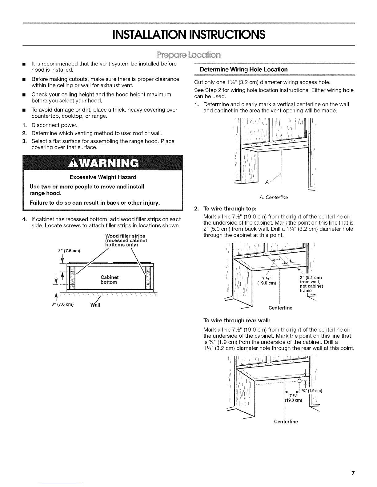
Cut only one 1V4" (3.2 cm) diameter wiring access hole.
See Step 2 for wiring hole location instructions. Either wiring hole
can be used.
1. Determine and clearly mark a vertical centerline on the wall
and cabinet in the area the vent opening will be made.
'/!11
Excessive Weight Hazard
Use two or more people to move and install
range hood.
Failure to do so can result in back or other injury.
4. If cabinet has recessed bottom, add wood filler strips on each
side. Locate screws to attach filler strips in locations shown.
Wood filler strips
(recessed cabinet
bottoms only)
(7.6 cm)
3" (7.6 cm) Wall
L_
A. Centerline
2,
To wire through top:
Mark a line 71/2'' (19.0 cm) from the right of the centerline on
the underside of the cabinet. Mark the point on this line that is
2" (5.0 cm) from back wall. Drill a 1V4"(3.2 cm) diameter hole
through the cabinet at this point.
7 1/2it
(19.0 cm) I
i
i
i
Centerline
To wire through rear wall:
Mark a line 71/2'' (19.0 cm) from the right of the centerline on
the underside of the cabinet. Mark the point on this line that
is 3/4"(1.9 cm) from the underside of the cabinet. Drill a
1V4" (3.2 cm) diameter hole through the rear wall at this point.
2" (5.1cm)
from wall,
not cabinet
frame
i(19.0cm)
i
I 71/2'' [_
i
i
Centerline
HII
3/4"(1.9 ore)
Page 8
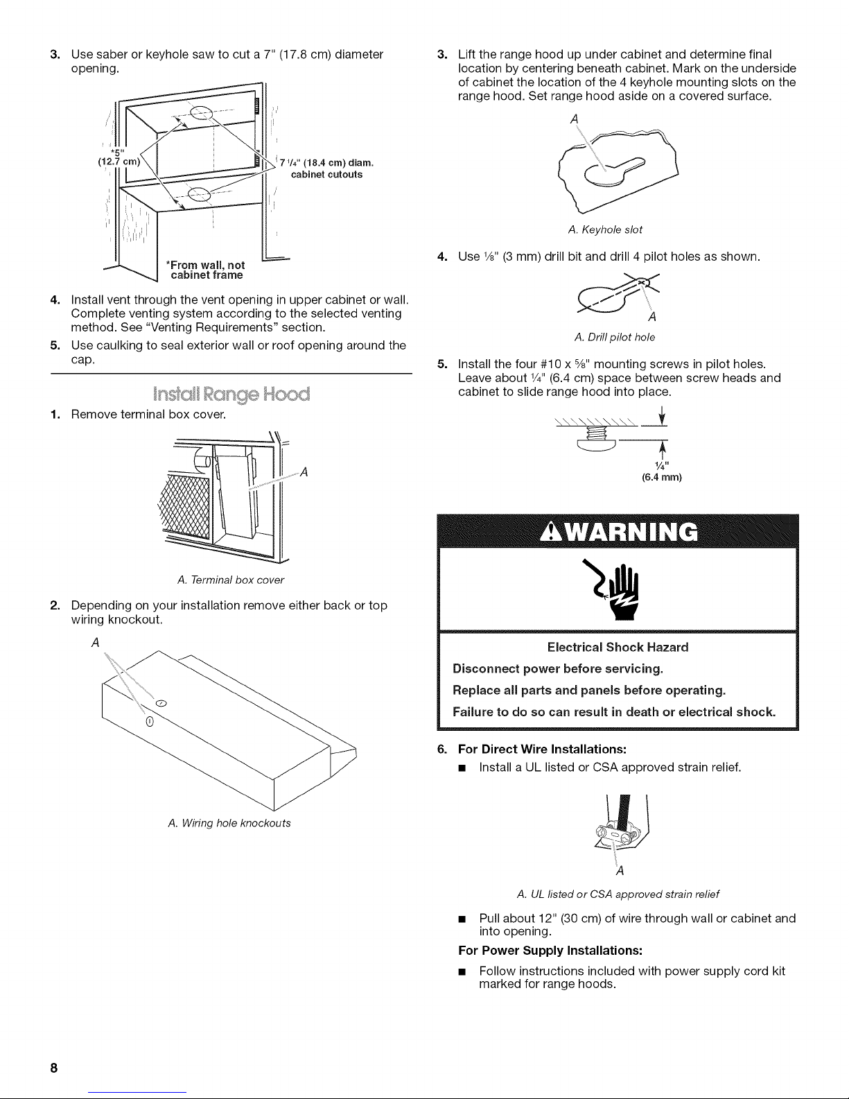
3.
Use saber or keyhole saw to cut a 7" (17.8 cm) diameter
opening.
71/4" (18.4 cm) diam.
cabinet cutouts
*From wall, not
cabinet frame
4. Install vent through the vent opening in upper cabinet or wall.
Complete venting system according to the selected venting
method. See "Venting Requirements" section.
5. Use caulking to seal exterior wall or roof opening around the
cap.
c tsge blo
1.
Remove terminal box cover.
3.
Lift the range hood up under cabinet and determine final
location by centering beneath cabinet. Mark on the underside
of cabinet the location of the 4 keyhole mounting slots on the
range hood. Set range hood aside on a covered surface.
A
A. Keyhole slot
4.
Use V8"(3 mm) drill bit and drill 4 pilot holes as shown.
A
A.Drill pilot hole
5.
Install the four #10 x 5/8"mounting screws in pilot holes.
Leave about V4"(6.4 cm) space between screw heads and
cabinet to slide range hood into place.
\\\\\\\\\\ _f
A. Terminal box cover
2.
Depending on your installation remove either back or top
wiring knockout.
A. Wiring hole knockouts
1/'4"
(6.4 mm)
Electrical Shock Hazard
Disconnect power before servicing.
Replace all parts and panels before operating.
Failure to do so can result in death or electrical shock.
6. For Direct Wire Installations:
• Install a UL listed or CSA approved strain relief.
8
A
A. UL listed or CSA approved strain relief
• Pull about 12" (30 cm) of wire through wall or cabinet and
into opening.
For Power Supply Installations:
• Follow instructions included with power supply cord kit
marked for range hoods.
Page 9

7. Using 2 people, lift range hood into final position, feeding
electrical wire through wiring opening. Position the range
hood so that the large end of the keyhole slots are over the
screws. Then push the hood toward the wall so that the
screws are in the neck of the slots. Tighten mounting screws
to cabinet, making sure mounting screws are in narrow neck
of slots.
8. Check that the damper, if used, rotates up and down freely.
9. Connect ventwork to hood. Seal joints with clamps to make
secure and airtight.
_,.,.,,_£S(,,_.,0t'
Install 75-watt (max.) Incandescent Light Bulb
1. Squeeze the plastic lens cover and remove it from the hood.
B
A
/
A. Light bulb socket
B. Lens cover
2. Screw light bulb into socket.
3. Replace lens cover by squeezing cover and inserting tabs
into slots.
Fire Hazard
Electrically ground the blower.
Use copper wire.
Connect ground wire to green ground screw in
terminaJ box.
Failure to do so can result in death, fire, or
electrical shock.
Direct Wire Installation
1=
Connect the white wire of the home power supply with the
white wire in the range hood using a UL listed twist-on
connector.
............i................. i
E
A. White wires
B. Black wires
C. Green ground screw
D. Ground wire
E.UL fisted or CSA approved strain relief
Check Range Hood Operation
1. Check light operation only by pressing light button.
2. Check operation of fan by pressing button to Hi and Lo
positions.
3. If the range hood does not operate, check to see whether a
circuit breaker has tripped or a house fuse has blown.
NOTE: To get the most efficient use from your new range hood,
read the "Range Hood Use" section.
2. Connect the black wire of the home power supply with the
black wire in the range hood using a UL listed twist-on
connector.
3. Connect ground wire (green or bare) of home power supply to
the green ground screw in the terminal box.
4=
Tighten strain relief screws.
5.
Install the terminal box cover.
6.
Reconnect power.
Page 10
RANGE HOOD USE
The range hood is designed to remove smoke, cooking vapors
and odors from the cooktop area. For best results, start the hood
before cooking and allow it to operate several minutes after the
cooking is complete to clear all smoke and odors from the
kitchen.
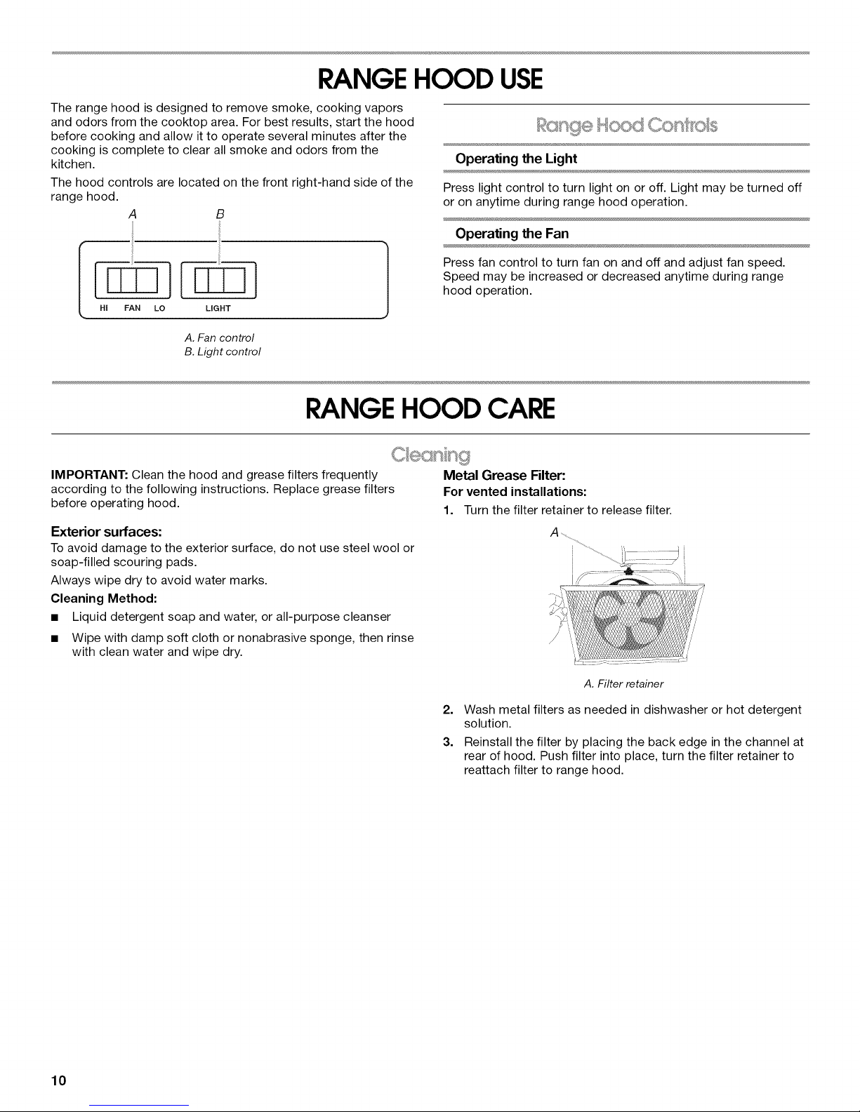
The hood controls are located on the front right-hand side of the
range hood.
A B
HI FAN LO LIGHT
A. Fan control
B. Light control
RANGE HOOD CARE
%oe .......,,S _,,,,,;,_:_
Operating the Light
Press light control to turn light on or off. Light may be turned off
or on anytime during range hood operation.
Operating the Fan
Press fan control to turn fan on and off and adjust fan speed.
Speed may be increased or decreased anytime during range
hood operation.
IMPORTANT: Clean the hood and grease filters frequently
according to the following instructions. Replace grease filters
before operating hood.
Exterior surfaces;
To avoid damage to the exterior surface, do not use steel wool or
soap-filled scouring pads.
Always wipe dry to avoid water marks.
Cleaning Method:
• Liquid detergent soap and water, or all-purpose cleanser
• Wipe with damp soft cloth or nonabrasive sponge, then rinse
with clean water and wipe dry.
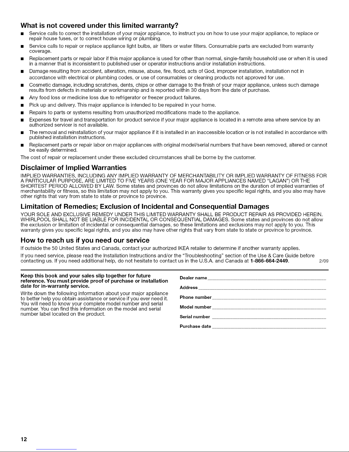
Metal Grease Filter:
For vented installations:
1. Turn the filter retainer to release filter.
A. Filter retainer
2. Wash metal filters as needed in dishwasher or hot detergent
solution.
3. Reinstall the filter by placing the back edge in the channel at
rear of hood. Push filter into place, turn the filter retainer to
reattach filter to range hood.
10
Page 11

ASSISTANCEOR SERVICE
When calling for assistance or service, please know the purchase
date and the complete model and serial number of your
appliance. This information will help us to better respond to your
request.
If you need replacement parts
If you need to order replacement parts, we recommend that you
use only factory specified parts. Factory specified parts will fit
right and work right because they are made with the same
precision used to build every new IKEA® appliance.
To locate factory specified parts in your area, call us or your
nearest designated service center.
n _s,eUSA
Call the Whirlpool Customer eXperience Center
toll free: 1-866-664-2449.
Our consultants provide assistance with:
• Features and specifications on our full line of appliances.
• Installation information.
Use and maintenance procedures.
Accessory and repair parts sales.
Specialized customer assistance (Spanish speaking, hearing
impaired, limited vision, etc.).
Referrals to local dealers, repair parts distributors and service
companies. Whirlpool designated service technicians are
trained to fulfill the product warranty and provide after-
warranty service, anywhere in the United States.
To locate the Whirlpool designated service company inyour
area, you can also look in your telephone directory Yellow
Pages.
For further assistance
If you need further assistance, you can write to Whirlpool
Corporation with any questions or concerns at:
IKEA Brand Home Appliances
Customer eXperience Center
553 Benson Road
Benton Harbor, MI 49022-2692
Please include a daytime phone number in your correspondence.
Call the Whirlpool Canada LP Customer eXperience Centre toll
free: 1-866-664-2449.
Our consultants provide assistance with:
• Features and specifications on our full line of appliances.
• Use and maintenance procedures.
• Accessory and repair parts sales.
• Referrals to local dealers, repair parts distributors, and
service companies. Whirlpool Canada LP designated service
technicians are trained to fulfill the product warranty and
provide after-warranty service, anywhere in Canada.
For further assistance
If you need further assistance, you can write to Whirlpool
Canada LP with any questions or concerns at:
Customer eXperience Centre
Whirlpool Canada LP
1901 Minnesota Court
Mississauga, Ontario L5N 3A7
Please include a daytime phone number inyour correspondence.
IKEAMAJOR APPLIANCEWARRANTY
How long is the IKEA limited warranty valid?
This limited warranty is valid for five years from the date of purchase, when this major appliance is operated and maintained according
to instructions attached to or furnished with the product, unless the appliance is named LAGAN in which case this limited warranty is
valid for one year from the date of purchase. This limited warranty is valid only in the United States or Canada and applies only when the
major appliance is used in the country inwhich it was purchased. Proof of original purchase date is required to obtain service under this
limited warranty.
Which appliances are not covered by the IKEA five (5) year limited warranty?
For major appliances named "LAGAN", this limited warranty is valid for one year from the date of purchase.
Who will execute the service?
This limited warranty is provided by Whirlpool Corporation or Whirlpool Canada LP (hereafter "Whirlpool"). Service must be provided by
a Whirlpool designated service company.
What does this limited warranty cover?
The limited warranty will pay for factory specified parts and repair labor to correct defects in materials or workmanship that existed
when the major appliance was purchased. The exceptions are specified under the headline "What is not covered under this limited
warranty?".
What will be done to correct the problem?
The designated service company will examine the product and decide, at its sole discretion, if it is covered under this limited warranty.
If considered covered, the designated service company will then repair the defect. Your sole and exclusive remedy under this limited
warranty shall be product repair as provided herein.
11
Page 12
What is not covered under this limited warranty?
• Service calls to correct the installation of your major appliance, to instruct you on how to use your major appliance, to replace or
repair house fuses, or to correct house wiring or plumbing.
• Service calls to repair or replace appliance light bulbs, air filters or water filters. Consumable parts are excluded from warranty
coverage.
• Replacement parts or repair labor if this major appliance is used for other than normal, single-family household use or when it is used
in a manner that is inconsistent to published user or operator instructions and/or installation instructions.
• Damage resulting from accident, alteration, misuse, abuse, fire, flood, acts of God, improper installation, installation not in
accordance with electrical or plumbing codes, or use of consumables or cleaning products not approved for use.
• Cosmetic damage, including scratches, dents, chips or other damage to the finish of your major appliance, unless such damage
results from defects in materials or workmanship and is reported within 30 days from the date of purchase.
• Any food loss or medicine loss due to refrigerator or freezer product failures.
• Pick up and delivery. This major appliance is intended to be repaired in your home.
• Repairs to parts or systems resulting from unauthorized modifications made to the appliance.
• Expenses for travel and transportation for product service if your major appliance is located in a remote area where service by an
authorized servicer is not available.
• The removal and reinstallation of your major appliance if it is installed in an inaccessible location or is not installed in accordance with
published installation instructions.
• Replacement parts or repair labor on major appliances with original model/serial numbers that have been removed, altered or cannot
be easily determined.
The cost of repair or replacement under these excluded circumstances shall be borne by the customer.
Disclaimer of Implied Warranties
IMPLIED WARRANTIES, INCLUDING ANY IMPLIED WARRANTY OF MERCHANTABILITY OR IMPLIED WARRANTY OF FITNESS FOR
A PARTICULAR PURPOSE, ARE LIMITED TO FIVE YEARS (ONE YEAR FOR MAJOR APPLIANCES NAMED "LAGAN") OR THE
SHORTEST PERIOD ALLOWED BY LAW. Some states and provinces do not allow limitations on the duration of implied warranties of
merchantability or fitness, so this limitation may not apply to you. This warranty gives you specific legal rights, and you also may have
other rights that vary from state to state or province to province.
Limitation of Remedies; Exclusion of Incidental and Consequential Damages
YOUR SOLE AND EXCLUSIVE REMEDY UNDER THIS LIMITED WARRANTY SHALL BE PRODUCT REPAIR AS PROVIDED HEREIN.
WHIRLPOOL SHALL NOT BE LIABLE FOR INCIDENTAL OR CONSEQUENTIAL DAMAGES. Some states and provinces do not allow
the exclusion or limitation of incidental or consequential damages, so these limitations and exclusions may not apply to you. This
warranty gives you specific legal rights, and you also may have other rights that vary from state to state or province to province.
How to reach us if you need our service
If outside the 50 United States and Canada, contact your authorized IKEA retailer to determine if another warranty applies.
If you need service, please read the Installation Instructions and/or the "Troubleshooting" section of the Use & Care Guide before
contacting us. If you need additional help, do not hesitate to contact us in the U.S.A. and Canada at 1-866-664-2449. 2/09
Keep this book and your sales slip together for future
reference. You must provide proof of purchase or installation
date for in-warranty service.
Write down the following information about your major appliance
to better help you obtain assistance or service if you ever need it.
You will need to know your complete model number and serial
number. You can find this information on the model and serial
number label located on the product.
Dealer name
Address
Phone number
Model number
Serial number
Purchase date
12
Page 13
SECURITEDELA HOTTEDECUlSlNIERE
Votre securite et celle des autres est tres importante.
Nous donnons de nombreux messages de s_curit_ importants dans ce manuel et sur votre appareil m_nager. Assurez-vous de
toujours lire tousles messages de s_curit_ et de vous y conformer.
Ce symbole d'alerte de s_curit_ vous signale les dangers potentiels de d_c_s et de blessures graves &vous
et & d'autres.
Voici le symbole d'alerte de s_curit&
Tousles messages de s_curit_ suivront le symbole d'alerte de s_curit_ et le mot "DANGER" ou
"AVERTISSEMENT". Ces mots signifient •
Risque possible de d_cbs ou de blessure grave si vous ne
suivez pas imm_diatement les instructions.
Risque possible de d_cbs ou de blessure grave si vous
ne suivez pas les instructions.
Tous les messages de s_curit_ vous diront quel est le danger potentiel et vous disent comment r_duire le risque de blessure et
ce qui peut se produire en cas de non-respect des instructions.
13
Page 14

IMPORTANTES iNSTRUCTiONS DE SECURITE
AVERTISSEIVIENT : POUR REDUIRE LE RISQUE
D'INCENDIE, CHOC ¢:LECTRIQUE OU DOMMAGES
CORPORELS, RESPECTER LES INSTRUCTIONS
SUIVANTES :
m Utiliser cet appareil uniquement dans les applications
envisag6es par le fabricant. Pour toute question, contacter
le fabricant.
m Avant d'entreprendre un travail d'entretien ou de nettoyage,
interrompre I'alimentation de la hotte au niveau du tableau
de disjoncteurs, et verrouiller le tableau de disjoncteurs
pour emp6cher tout r@ablissement accidentel de
I'alimentation du circuit. Lorsqu'il n'est pas possible de
verrouiller le tableau de disjoncteurs, placer sur le tableau
de disjoncteurs une @iquette d'avertissement pro6minente
interdisant le r@ablissement de I'alimentation.
m Tout travail d'installation ou c&blage 61ectrique doit 6tre
r6alis6 par une personne qualifi6e, dans le respect des
prescriptions de tousles codes et normes applicables, y
compris les codes du b&timent et de protection contre les
incendies.
m Une source d'air de d6bit suffisant est n6cessaire pour le
fonctionnement correct de tout appareil & gaz (combustion
et 6vacuation des gaz &combustion par la chemin6e), pour
qu'il n'y ait pas de reflux des gaz de combustion. Respecter
les directives du fabricant de 1'6quipement de chauffage et
les prescriptions des normes de s6curit6 - comme celles
publi6es par la National Fire Protection Association (NFPA)
et I'American Society for Heating, Refrigeration and Air
Conditioning Engineers (ASHRAE), et les prescriptions des
autorit6s r6glementaires locales.
m Lors d'op@ations de d6coupage et de perqage dans un mur
ou un plafond, veiller & ne pas endommager les c&blages
61ectriques ou canalisations qui peuvent s'y trouver.
m Les ventilateurs d'6vacuation doivent toujours d6charger
I'air & I'ext@ieur.
IVilSE EN GARDE : Cet appareil est con_:u uniquement
pour la ventilation g6n@ale. Ne pas I'utiliser pour I'extraction
de mati_res ou vapeurs dangereuses ou explosives.
MISE EN GARDE : Pour minimiser le risque d'incendie
et 6vacuer ad6quatement les gaz, veiller &acheminer I'air
aspir6 par un conduit jusqu'b, I'ext@ieur - ne pas d6charger
I'air aspir6 dans un espace vide du b&timent comme une
cavit6 murale, un plafond, un grenier, un vide sanitaire ou
un garage.
AVERTISSEMENT : POUR R¢:DUIRE LE RISQUE
D'INCENDIE, UTILISER UNIQUEMENT DES CONDUITS
MI2TALLIQUES.
AVERTISSEIVIENT : POUR MINIMISER LE RISQUE
D'UN FEU DE GRAISSE SUR LA CUISINIF:RE :
[] Ne jamais laisser un 616ment de surface fonctionner &
puissance de chauffage maximale sans surveillance. Un
renversement/d6bordement de mati_re graisseuse pourrait
provoquer une inflammation et la g6n@ation de fum6e.
Utiliser une puissance de chauffage moyenne ou basse
pour le chauffage d'huile.
[] Veiller & toujours faire fonctionner le ventilateur de la hotte
Iors de la cuisson avec une puissance de chauffage 61ev6e
ou Iors de la cuisson d'un mets & flamber (& savoir cr6pes
Suzette, cerise jubil6e, steak au poivre flamb6).
[] Nettoyer fr6quemment les ventilateurs d'extraction. Veiller &
ne pas laisser la graisse s'accumuler sur les surfaces du
ventilateur ou des filtres.
[] Utiliser toujours un ustensile de taille appropri6e. Utiliser
toujours un ustensile adapt6 & la taille de 1'616ment
chauffant.
AVERTISSEMENT : POUR RE_DUIRE LE RISQUE DE
DOMMAGES CORPORELS APRF:S LE DECLENCHEMENT
D'UN FEU DE GRAISSE SUR LA CUISINI_:RE, APPLIQUER
LES RECOMMANDATIONS SUIVANTES :a
[] Placer sur le r6cipient un couvercle bien ajust6, une t61e &
biscuits ou un plateau m6tallique POUR ETOUFFER LES
FLAMMES, puis 6teindre le brt_leur. VEILLER ,&.¢:VITER
LES BRULURES. Si les flammes ne s'@eignent pas
imm6diatement, ¢:VACUER LA PIECE ET APPELER LES
POMPIERS.
[] NE JAMAIS PRENDRE EN MAIN UN RECIPIENT
ENFLAMME - vous risquez de vous brQler.
[] NE PAS UTILISER D'EAU, ni un torchon humide - ceci
pourrait provoquer une explosion de vapeur brQlante.
[] Utiliser un extincteur SEULEMENT si:
- II s'agit d'un extincteur de classe ABC, dont on connaft le
fonctionnement.
- II s'agit d'un petit feu encore limit6 & I'endroit oQ il s'est
d6clar&
- Les pompiers ont 6t6 contact6s.
- II est possible de garder le dos orient6 vers une sortie
pendant I'op@ation de lutte contre le feu.
aRecommandations tir6es des conseils de s6curit6 en cas
d'incendie de cuisine publi6s par la NFPA.
[] AVERTISSEMENT : Pour r6duire le risque d'incendie
ou de choc 61ectrique, ne pas utiliser ce ventilateur avec un
quelconque dispositif de r6glage de la vitesse & semi-
conducteurs.
CONSERVEZ CES iNSTRUCTiONS
14
Page 15

EXIGENCESD'INSTALLATION
(o}u csg®®
Rassembler les outils et pieces necessaires avant de commencer
I'installation. Lire et suivre les instructions fournies avec les outils
indiques ici.
Outils n_cessaires
• Niveau
• Foret
• Foret de 11¼"
• Foret de 1/8"(3 mm) pour avant-trous
• Crayon
• Pince
• Pince & denuder ou couteau utilitaire
• Metre-ruban ou regle
• Pistolet &calfeutrage et compose de calfeutrage resistant
aux intemperies
• Tournevis Phillips
• Scie sauteuse ou scie & guichet
• Brides de serrage pour conduit d'evacuation
• Cisaille de ferblantier
• Compas ou gabarit de diametre 7" (17,8 cm)
Pi_ces fournies
Verifier que toutes les pieces sont presentes.
• Sachet de documents (1)
• Sachet de pieces de quincaillerie (1)
• Clapet anti-reflux rond de 7" (17,8 cm)
Pi_ces n_cessaires
• Serre-c&ble de 1/2"(12,5 mm) (homologation UL ou CSA)
• Lampe & incandescence - 75 watts maximum
• C&ble d'alimentation electrique
• Conduit d'evacuation metallique, dia. 7" (17,8 cm)
Pour placards avec cavit_ au fond :
• Deux tringles d'appui de largeur 2" (5,1 cm). Longueur et
epaisseur selon les dimensions du placard.
• Quatre vis A bois & t_te plate ou vis A metaux avec rondelle et
ecrou, pour la fixation des tringles d'appui.
IMPORTANT : Observer les dispositions de tousles codes et
reglements en vigueur.
• C'est a I'installateur qulncombe la responsabilite de
respecter les distances de separation specifiees sur la plaque
signaletique de I'appareil. La plaque signaletique est situee
I'interieur de la hotte, sur la paroi arriere.
• Insta(ler la hotte de cuisiniere a distance de toute zone
exposee a des courants d'air, comme fen_tres, portes et
bouches de chauffage.
• Respecter les dimensions indiquees pour les ouvertures
decouper dans les placards; ces dimensions tiennent compte
des valeurs minimales des degagements de separation.
Avant d'effectuer des decoupages, consulter les instructions
d'installation fournies par le fabricant de la table de cuisson/
cuisiniere.
• On doit disposer d'une prise de courant electrique reliee a la
terre. Voir la section "Specifications electriques".
• La hotte est configuree a I'usine pour la decharge a travers le
toit ou un mur.
• Assurer I'etancheite au niveau de chaque ouverture
decoupee dans le plafond ou lemur pour I'installation de la
hotte de cuisiniere.
Installation dans une r_sidence mobile
L'installation de cette hotte doit satisfaire aux exigences de la
norme Manufactured Home Construction Safety Standards, Titre
24 CFR, partie 328 (anciennement Federal Standard for Mobile
Home Construction and Safety, titre 24, HUD, partie 280); Iorsque
cette norme n'est pas applicable, I'installation doit satisfaire aux
criteres de la plus recente edition de la norme Manufactured
Home Installation 1982 (Manufactured Home Sites, Communities
and Setups)ANSI A225.1/NFPA 501A*, ou des codes et
reglements Iocaux.
Dimensions du produit
(75,9 crn) (30,5 crn)
(15,2 crn)
\
\\
\\
17%" J, _._<" Axe central
(44,8 cn_) 3/4,,_19,_ cm ) 7V2"
) (19,1crn)
Xw
Opercuies arrachabies
hotte
15
Page 16

D_gagements de s_paration & respecter
Le systeme d'evacuation doit comporter un clapet. Si la
bouche de decharge murale ou par le toit comporte un
clapet, ne pas utiliser le clapet fourni avec la hotte de
cuisiniere.
• Autour de la bouche de decharge a I'exterieur, assurer
I'etanch6it6 avec un produit de calfeutrage.
• La taille du conduit doit _tre uniforme.
distance suqg_ree
du bas du placard
la surface de cuisson
45,7 cm) rain.
61,0 cra) max.
sup_
plande travail
18" (45,7 cra) rain.
hauteur
_Jacarddu bas
6"(91,4
largeur I
d'ouverture
du placard
30" (76,2
_rofondeur
_lacard
Installations pour r_gions & climat froid
Dans le circuit d'evacuation, on devrait installer un clapet anti-
reflux additionnel pour minimiser le reflux d'air froid, ainsi qu'un
element d'isolation thermique non metallique pour minimiser le
transfert de chaleur par conduction vers I'exterieur. Le clapet
anti-reflux doit _tre place du c6te air froid par rapport & I'element
d'isolation thermique.
L'element d'isolation thermique doit _tre aussi proche que
possible de I'endroit oQ le systeme d'evacuation s'introduit dans
la partie chauffee de la maison.
Air d'appoint
Le code du b&timent local peut exiger I'emploi d'un systeme de
renouvellement de I'air/introduction d'air d'appoint, Iors de
I'utilisation d'un systeme d'aspiration de debit superieur &une
valeur (pieds cubes par minute) specifiee. Le debit specifie, en
pieds cubes par minute, est variable d'une juridiction &une autre.
Consulter un professionnel des installations de chauffage
ventilation/climatisation au sujet des exigences specifiques
applicables dans la juridiction locale.
M_thodes d'_vacuation
La sortie & I'exterieur du circuit d'evacuation peut se faire &
travers le toit ou & travers un mur. Pour la realisation du circuit
d'evacuation, utiliser du conduit de dia. 7" (17,8 cm) avec une
Iongueur maximum de 26 pi (7,9 m).
Sortie verticale a travers Sortie horizontale a travers
le toit le tour
,,_.._._......... CO O_:sl_C£_ ..................._,.._,.,,.......
• Le syst@me doit d@charger I'air a I'ext@rieur.
• Ne pas terminer le conduit d'@vacuation dans un grenier ou
dans un autre espace ferm&
• Ne pas utiliser une bouche de decharge murale de
4" (10,2 cm) normalement utilisee pour un equipement
de buanderie.
• Utiliser un conduit metallique uniquement. Un conduit en
metal rigide est recommande. Ne pas utiliser un conduit de
plastique ou en feuille metallique.
Pour un fonctionnement efficace et silencieux •
• Utiliser autant que possible des sections droites et minimiser
le nombre de coudes.
Ne pas utiliser plus de trois coudes a 90°.
Veiller & ce qu'il y ait une section droite de conduit de 24"
(61 cm) ou plus entre deux coudes, si on doit utiliser plus
d'un raccord coud&
• Ne pas installer 2 coudes ensemble.
• Au niveau de chaque jointure du conduit de decharge,
assurer I'etanch6it6 avec les brides de serrage pour conduit.
C
A. Conduit de 7" (17,8 cm)
travers le toit
B. Conduit rond : utiliser un clapet
de dia. 7" (17,8 cm) (acquisition
s_par_e)
C. 18" (45,7 cm) _ 24" (61,0 cm)
au-dessus de la surface de
cuisson
D. Bouche de d_charge _ travers
le toit
A ....
....... ,:/=
B
A. Conduit de 7" (17,8 cm) a
travers le mur
B. 18" (45,7 cm) a 24" (61,0 cm)
au-dessus de la surface de
cuisson
C. Bouche de d_charge murale
16
Page 17
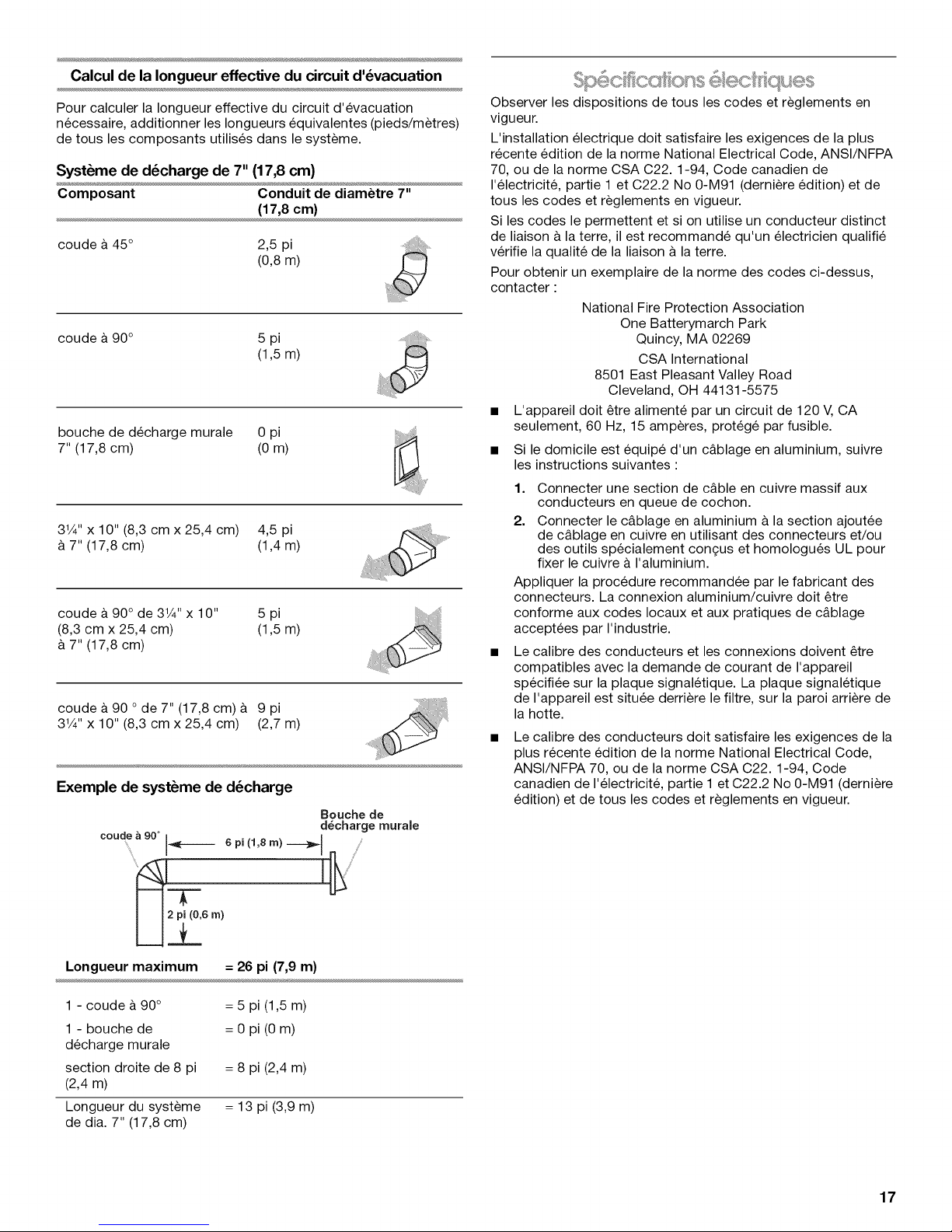
Calcul de la Iongueur effective du circuit d'_vacuation
Pour calculer la Iongueur effective du circuit d'evacuation
necessaire, additionner les Iongueurs equivalentes (pieds/metres)
de tousles composants utilises dans le systeme.
Syst_me de d_charge de 7" (17,8 cm)
Composant Conduit de diam_tre 7"
(17,8cm)
coude & 45° 2,5 pi
(0,8m)
coude & 90° 5 pi
(1,5m)
bouche de decharge murale 0 pi
7" (17,8 cm) (0 m)
31/4'' x 10" (8,3 cm x 25,4 cm) 4,5 pi
&7" (17,8 cm) (1,4 m)
coude a 90° de 31/4"x 10" 5 pi
(8,3 cm x 25,4 cm) (1,5 m)
7" (17,8 cm)
coude a 90 ode 7" (17,8 cm) & 9 pi
31/4"x 10" (8,3 cm x 25,4 cm) (2,7 m)
_H_j
Exemple de syst_me de d_charge
Bouche de
d_charge rnurale
c°ud,ea9°° i_----_ 6pi(1,sm)-----}B_ I ....
Observer les dispositions de tousles codes et reglements en
vigueur.
L'installation electrique doit satisfaire les exigences de la plus
recente edition de la norme National Electrical Code, ANSl/NFPA
70, ou de la norme CSA C22.1-94, Code canadien de
I'electricite, partie 1 et C22.2 No 0-M91 (derniere edition) et de
tousles codes et reglements en vigueur.
Si les codes le permettent et si on utilise un conducteur distinct
de liaison a la terre, il est recommande qu'un electricien qualifie
verifie la qualite de la liaison & la terre.
Pour obtenir un exemplaire de la norme des codes ci-dessus,
contacter :
National Fire Protection Association
One Batterymarch Park
Quincy, MA 02269
CSA International
8501 East Pleasant Valley Road
Cleveland, OH 44131-5575
• L'appareil doit _tre alimente par un circuit de 120 V, CA
seulement, 60 Hz, 15 amperes, protege par fusible.
• Si le domicile est equipe d'un c&blage en aluminium, suivre
les instructions suivantes :
1. Connecter une section de c&ble en cuivre massif aux
conducteurs en queue de cochon.
2. Connecter le c&blage en aluminium a la section ajoutee
de c&blage en cuivre en utilisant des connecteurs et/ou
des outils specialement con(_us et homologues UL pour
fixer le cuivre a I'aluminium.
Appliquer la procedure recommandee par le fabricant des
connecteurs. La connexion aluminium/cuivre doit _tre
conforme aux codes Iocaux et aux pratiques de c&blage
acceptees par I'industrie.
Le calibre des conducteurs et les connexions doivent _tre
compatibles avec la demande de courant de I'appareil
specifiee sur la plaque signaletique. La plaque signaletique
de I'appareil est situee derriere le filtre, sur la paroi arriere de
la hotte.
Le calibre des conducteurs doit satisfaire les exigences de la
plus recente edition de la norme National Electrical Code,
ANSl/NFPA 70, ou de la norme CSA C22.1-94, Code
canadien de I'electricite, partie 1 et C22.2 No 0-M91 (derniere
edition) et de tousles codes et reglements en vigueur.
Longueur maximum = 26 pi (7,9 m)
1 - coude & 90°
1 - bouche de
decharge murale
section droite de 8 pi
(2,4 m)
Longueur du systeme
de dia. 7" (17,8 cm)
= 5 pi (1,5 m)
= 0 pi (0 m)
= 8 pi (2,4 m)
= 13 pi (3,9 m)
17
Page 18

INSTRUCTIONSD'INSTALLATION
• II est recommande d'installer le conduit de decharge avant de
proceder a I'installation de la hotte.
• Avant d'executer les decoupages, verifier la disponibilite d'un
espace de passage suffisant dans le plafond ou lemur pour
le conduit d'evacuation.
Avant de selectionner la hotte & installer, mesurer la hauteur
libre sous plafond et la hauteur maximum disponible sous la
hotte.
Pour eviter des deteriorations et pour la proprete, placer un
epais materiau de recouvrement sur le plan de travail, la table
de cuisson ou la cuisiniere.
1. Deconnecter la source de courant electrique.
2. Determiner la methode d'extraction & utiliser •& travers le toit
ou & travers lemur.
3.
Selectionner une surface plane pour I'assemblage de la
hotte. Placer le materiau de protection sur cette surface.
Risque du poJds excessif
Utiiiser deux ou plus de personnes pour d_placer et
installer la hotte de la cuisini_re.
Le non=respect de cette instruction peut causer
une blessure au dos ou d'autre blessure.
1.
Sur le mur et le placard dans la zone oQ le passage du
conduit d'evacuation va _tre realis6, determiner et tracer I'axe
central vertical.
A. Axe central vertical
2.
C_blage a travers le sommet du placard :
Tracer une ligne & 71/2"(19,0 cm) & droite de I'axe central, sur
la face inferieure du placard. Sur cette ligne, marquer le point
situe & 2" (5,0 cm) du mur arriere. Percer en ce point un trou
de 11¼"(3,2 cm) de diametre a travers le placard.
4.
Si le fond du placard forme une cavite, ajouter des tringles
d'appui en bois de chaque c6t& Trouver les vis pour fixer les
tringles d'appui aux emplacements indiqu6s.
Tringles d'appui en bois
3" placard avec cavitY)
(7,6 ore) _
3" Mur
(7,6 crn)
(seu]ement pourfond de
/
D_terminer I'emplacement du trou de passage du c&ble
Percer seulement un trou de passage de 11¼"(3,2 cm) de
diametre pour le c&ble d'alimentation.
Voir I'etape 2 pour des instructions sur I'emplacement du trou de
passage du c&ble. On peut utiliser I'un ou I'autre des
emplacements indiqu_s pour le trou de passage du c&ble.
7½" I
(19,0cm) j
Axe central
2" (5,1 crn) a partir
du rnur, et non du
cadre du placard
C&blage a travers le tour arri_re :
Tracer une ligne & 71/2'' (19,0 cm) & droite de I'axe central, sur
la face inferieure du placard. Sur cette ligne, marquer le point
situe & %" (1,9 cm) de la face inferieure du placard. Percer en
ce point un trou de 1W' (3,2 cm) de diametre & travers le mur
arriere.
18
Page 19

3.
Utiliser une scie sauteuse ou une scie a guichet pour
decouper une ouverture de 7" (17,8 cm) de diam_tre.
'*5" 71/4" (18,4 cm) diam.
(12,7 ouvertures
i,
'i
*A partir du rnur,
et non du cadre
du placard
d6coup6es
darts le placard
/
3.
Soulever la hotte sous le placard et determiner sa position
d'installation finale en la centrant sous le placard. Sur la face
inferieure du placard, marquer I'emplacement des 4 trous de
montage sur la hotte. Placer la hotte a part sur une surface
proteg6e.
A
A. Trou pour vis de montage
4=
Avec un foret de V8"(3,0 mm), percer 4 avant-trous - voir
I'illustration.
4. Installer le conduit d'evacuation &travers les ouvertures
d6coupees dans le placard mural ou le mur. Achever
I'installation du systeme d'evacuation conformement & la
methode d'evacuation s61ectionnee. Voir la section
"Exigences concernant I'evacuation".
5. Autour de la bouche de decharge a I'exterieur, assurer
I'etanch6it6 avec un produit de calfeutrage.
1=
Oter le couvercle du boitier de connexion.
A. Couvercle du bottler de connexion
2.
Selon la configuration d'installation, enlever un opercule
arrachable a I'arriere ou au sommet.
A
A. Pergage des avant-trous
5=
Installer les quatre vis de montage n° 10 de 5/8"dans les
avant-trous. Laisser un espace d'environ 1¼.(6,4 cm) entre
les t6tes des vis et le placard pour glisser la hotte en place.
\\\\\\\\\\\
1/4"
(6,4 ram)
Risque de choc 61ectrique
D6connecter la source de courant 61ectrique avant
rentretien.
Replacer pi6ces et panneaux avant de faire la remise
en marche.
Le non=respect de ces instructions peut causer
un d6c6s ou un choc 61ectrique.
A. Opercules arrachables
6. Pour les installations a raccordement direct :
• Installer un serre-cAble (homologation UL ou CSA).
A
A. Serre-c_ble (homologation UL ou CSA)
• Tirer environ 12" (30 cm) de cfible a travers lemur ou le
placard et dans I'ouverture.
19
Page 20

Pour les installations avec cordon d'alimentation
_lectrique :
• Suivre les instructions fournies avec I'ensemble du
cordon d'alimentation electrique pour hottes de
cuisiniere.
7. A deux personnes, soulever la hotte jusqu'& sa position
finale, tout en inserant le c&ble electrique & travers le trou de
passage du c&ble. Positionner les trous allonges de la hotte
par-dessus la t_te des vis. Puis pousser la hotte vers le mur
pour engager la partie etroite des trous sur les vis de fixation.
Serrer les vis de montage sur le placard, en veillant ace que
chaque vis reste dans la partie etroite du trou de la hotte.
8. Le cas ech6ant, verifier que le clapet anti-reflux peut
manceuvrer librement vers le haut et vers le bas.
9. Raccorder le circuit d'evacuation a la hotte. Assurer
I'etanch6it6 des jointures avec des brides pour conduits.
Risque d'incendie
Relier le ventilateur a la terre.
Utiliser du fil en cuivre.
Brancher le fil reli_ a la terre a la vis verte reli_e a la
terre darts la boite de la borne.
Le non=respect de ces instructions peut causer un
d_c_s, un incendie ou un choc _lectrique.
Raccordement par c&blage direct
1. Connecter ensemble le conducteur blanc du c&ble
d'alimentation et le conducteur blanc de la hotte, avec un
connecteur de ills (homologation UL).
2. Connecter ensemble le conducteur noir du c&ble
d'alimentation et le conducteur noir de la hotte, avec un
connecteur de fils (homologation UL).
3. Connecter le conducteur (vert ou nu) de liaison a la terre du
c&ble d'alimentation &la vis verte de liaison & la terre dans le
boitier de connexion.
4. Serrer les vis du serre-c&ble.
5. Reinstaller le couvercle du boitier de connexion.
6. Reconnecter la source de courant electrique.
_'_A_¸s_ _s_ _ _@_[_ o_ _
Installer une lampe _ incandescence de 75watts
(maximum).
1. Exercer une pression sur le cabochon de plastique pour
pouvoir le separer de la hotte.
B
A
/
A. Douille de la lampe
B. Cabochon
2=
Visser la lampe dans la douille.
3.
Reinstaller le cabochon : exercer une pression sur le
cabochon pour pouvoir inserer les pattes dans les ouvertures
d'insertion.
V6rifier le fonctionnement de la hotte
1. Verifier le fonctionnement de la lampe uniquement en
appuyant sur I'interrupteur de la lampe.
2. Verifier le fonctionnement du ventilateur en appuyant sur le
bouton (positions Hi [haut] et Lo [bas]).
3. Si la hotte ne fonctionne pas, determiner si le circuit est
correctement alimente (disjoncteur ouvert ou fusible grille?).
REMARQUE : Pour pouvoir tirer le plus grand parti de la hotte de
cuisiniere, lire la section "Utilisation de la hotte de cuisiniere".
E
A. Conducteurs blancs
B. Conducteurs noirs
C. Vis verte de liaison _ la terre
D. Conducteur de liaison _ la terre
E. Serre-c_ble (homologation UL ou CSA)
20
Page 21

UTILISATIONDELA HOTTEDECUlSlNIERE
La hotte de cuisiniere est con£;ue pour extraire fumee, vapeurs de
cuisson et odeurs au-dessus de la table de cuisson. Pour obtenir
les meilleurs resultats, mettre le ventilateur de la hotte en marche
avant d'entreprendre une cuisson, et laisser le ventilateur
fonctionner pendant plusieurs minutes apres la fin d'une cuisson
pour pouvoir evacuer de la cuisine toute trace d'odeur de
cuisson, vapeur ou fumee.
Les commandes de la hotte sont situ6es sur la droite du panneau
de fagade de la hotte.
A B
HI FAN LO LIGHT
A. Commande du ventilateur
B. Commande d'_clairage
ENTRETIENDELA HOTTE
Fonctionnement de I'_clairage
Appuyer sur le bouton de commande d'eclairage pour
commander I'allumage ou I'extinction. On peut commander
I'allumage ou I'extinction de la lampe a tout moment pendant le
fonctionnement de la hotte.
Fonctionnement du ventilateur
Appuyer sur le bouton de commande du ventilateur pour
commander la mise en marche et I'arr_t du ventilateur et pour
regler la vitesse. On peut commander I'augmentation ou la
diminution de la vitesse a tout moment durant le fonctionnement
de la hotte.
IMPORTANT : Nettoyer frequemment la hotte et les filtres &
graisse en suivant les instructions suivantes. Reinstaller les filtres
&graisse avant de faire fonctionner la hotte.
Surfaces externes :
Pour eviter d'endommager la surface externe, ne pas utiliser un
produit de nettoyage abrasif ou un tampon de laine d'acier.
Toujours essuyer pour eviter de laisser des marques d'eau.
M6thode de nettoyage :
• Savon detergent liquide et eau, ou produit de nettoyage
polyvalent.
• Frotter avec un chiffon doux humide ou une eponge non
abrasive, puis rincer avec de I'eau propre et essuyer.
Filtre _ graisse m6tallique :
1. Fairepivoter la patte de retenue pour libererlefiltre.
A. Patte de retenue du filtre
2. Laver le filtre metallique selon le besoin au lave-vaisselle ou
avec une solution de detergent chaude.
3. Reinstaller le filtre en pla(_ant le bord arriere dans la rainure &
I'arriere de la hotte. Pousser le filtre en place; faire pivoter la
patte de retenue du filtre pour le fixer sur la hotte.
21
Page 22

ASSISTANCEOU SERVICE
Lors d'un appel pour assistance ou service, veuillez connaYtre la
date d'achat, le numero de modele et le numero de serie au
complet de I'appareil. Ces renseignements nous aideront & mieux
repondre a votre demande.
Si vous avez besoin de pieces de rechange
Si vous avez besoin de commander des pieces de rechange,
nous vous recommandons d'employer uniquement des pieces
specifiees par I'usine. Les pieces specifiees par I'usine
conviendront et fonctionneront bien parce qu'elles sont
fabriquees avec la m_me precision utilisee dans la fabrication de
chaque nouvel appareil IKEA®.
Pour Iocaliser des pieces specifiees par I'usine dans votre region,
nous appeler ou telephoner au centre de service designe le plus
proche.
Veuillez appeler sans frais le Centre d'eXperience a la clientele de
Whirlpool Canada LP au : 1-866-664-2449.
Nos consultants vous renseigneront sur les sujets suivants :
• Caracteristiques et specifications sur toute notre gamme
d'appareils electromenagers.
• Consignes d'utilisation et d'entretien.
• Ventes d'accessoires et de pieces de rechange.
• References aux marchands Iocaux, aux distributeurs de
pieces de rechange et aux compagnies de service. Les
techniciens de service designes par Whirlpool Canada LP
sont formes pour remplir la garantie des produits et fournir un
service apres la garantie, partout au Canada.
Pour plus d'assistance
Si vous avez besoin de plus d'assistance, vous pouvez
soumettre par ecrit toute question ou preoccupation & Whirlpool
Canada LP & I'adresse suivante :
Customer eXperience Center
Whirlpool Canada LP
1901 Minnesota Court
Mississauga, Ontario L5N 3A7
Veuillez inclure dans votre correspondance un numero de
telephone oQ on peut vous joindre dans la journee.
22
Page 23

GARANTIEDESGROSAPPAREILSMENAGERSIKEA
Pendant combien de temps la garantie limitde IKEA est-elle valide?
Cette garantie limitee est valide pendant cinq ans a compter de la date d'achat Iorsque ce gros appareil menager a et6 utilise et
entretenu conformement aux instructions jointes au produit ou fournies avec celui-ci, sauf si I'appareil porte le nom LAGAN, auquel cas
cette garantie limitee est valide pendant un an & compter de la date d'achat. Cette garantie limitee est valide uniquement aux Etats-
Unis ou au Canada et s'applique exclusivement Iorsque le gros appareil menager est utilise dans le pays oQ il a et6 achet& Une preuve
de la date d'achat d'origine est exigee pour obtenir un service dans le cadre de la presente garantie limitee.
Quels sont les appareils mdnagers non couverts par la garantie limitde IKEA de cinq (5) ans?
Pour les gros appareils menagers portant le nom "LAGAN", cette garantie limitee est valide pendant un an & compter de la date
d'achat.
Qui effectuera I'intervention d'entretien ou de rdparation?
Cette garantie limitee est fournie par Whirlpool Corporation ou Whirlpool Canada LP (ci-apres designees "Whirlpool"). Le service doit
etre fourni par une compagnie de service designee par Whirlpool.
Que couvre cette garantie limitde?
La garantie limitee paiera pour les pieces specifiees par I'usine et la main-d'ceuvre pour corriger les vices de materiaux ou de
fabrication qui existaient dej& Iorsque ce gros appareil menager a ete achet& Les exceptions figurent sous le titre "Quels sont les
elements non couverts par cette garantie limitee?".
Quelles mesures seront prises pour corriger le probl_me?
La compagnie de service designee examinera le produit et decidera, & sa seule discretion, si ce produit est couvert par cette garantie
limitee ou non. S'il est considere comme couvert, la compagnie de service designee corrigera le defaut. Le seul et exclusif recours du
client dans le cadre de la presente garantie limitee consiste en la reparation du produit telle que mentionne dans la presente.
Quels sont les dldments non couverts par cette garantie limitde?
• Les visites de service pour rectifier I'installation du gros appareil menager, montrer a I'utilisateur comment utiliser le gros appareil
menager, remplacer ou reparer des fusibles du domicile ou rectifier le c&blage ou la plomberie du domicile.
• Les visites de service pour reparer ou remplacer les ampoules electriques, les filtres & air ou les filtres & eau de I'appareil. Les pieces
consomptibles ne sont pas couvertes par la garantie.
• Les pieces de rechange ou la main-d'ceuvre Iorsque ce gros appareil menager est utilise &des fins autres que I'usage domestique
unifamilial normal ou Iorsque les instructions d'installation et/ou les instructions de I'operateur ou de I'utilisateur fournies ne sont pas
respectees.
• Les dommages imputables & : accident, modification, usage impropre ou abusif, incendie, inondation, actes de Dieu, installation
fautive ou installation non conforme aux codes d'electricite ou de plomberie ou I'utilisation de pieces consomptibles ou de produits
de nettoyage dont I'utilisation n'est pas approuvee.
• Les defauts d'apparence, notamment les eraflures, traces de choc, fissures ou tout autre dommage subi par le fini du gros appareil
menager, & moins que ces dommages ne resultent de vices de materiaux ou de fabrication et ne soient signales dans les 30 jours qui
suivent la date d'achat.
• Toute perte d'aliments ou de medicaments due & une defaillance du refrigerateur ou du congelateur.
• Uenlevement et la livraison. Ce gros appareil menager est con£_upour etre repare & domicile.
• Les reparations aux pieces ou systemes resultant d'une modification non autorisee faite & I'appareil.
• Les frais de deplacement et de transport pour une intervention sur un produit si le gros appareil menager est situe dans une region
eloignee oQ un service d'entretien autorise n'est pas disponible.
• Uenlevement et la reinstallation du gros appareil menager si celui-ci est installe dans un endroit inaccessible ou n'est pas installe
conformement aux instructions d'installation fournies.
• Les pieces de rechange ou la main-d'ceuvre pour les gros appareils menagers dont les numeros de modele/de serie ont ete enleves,
modifies ou ne peuvent pas etre facilement identifies.
Le coQt d'une reparation ou de pieces de rechange dans le cadre de ces circonstances exclues est &la charge du client.
Clause d'exondration de responsabilitd au titre des garanties imPlicites
LES GARANTIES IMPLICITES, Y COMPRIS LES GARANTIES APPLICABLES DE QUALITE MARCHANDE OU D'APTITUDE A UN
USAGE PARTI.CULLER,SONT LIMIT¢:ES A CINQ ANS (U.NAN POUR LES GROS APPAREILS M¢:NAGERS PORTANT LE NOM
"LAGAN") OU A LA PLUS COURTE P¢:RIODE AUTORISEE PAR LA LOI. Certains €:tats et provinces ne permettent pas de limitation sur
la duree de garanties implicites de qualite marchande ou d'aptitude &un usage particulier, de sorte que la limitation ci-dessus peut ne
pas etre applicable dans votre cas. Cette garantie vous confere des droits juridiques specifiques et vous pouvez egalement jouir
d'autres droits qui peuvent varier d'une juridiction & I'autre.
Limitation des recours; exclusion des dommages fortuits et indirects
LE SEUL ET EXCLUSIF RECOURS DU CLIENT DANS LE CADRE DE LA PR¢:SENTE GARANTIE LIMIT¢:E CONSISTE EN LA
R¢:PARATION PR¢:VUE CI-DESSUS. WHIRLPOOL N'ASSUME AUCUNE RESPONSABILIT¢: POUR LES DOMMAGES FORTUITS OU
INDIRECTS. Certains €:tats et certaines provinces ne permettent pas I'exclusion ou la limitation des dommages fortuits ou indirects de
sorte que ces limitations et exclusions peuvent ne pas etre applicables dans votre cas. Cette garantie vous confere des droits juridiques
specifiques et vous pouvez egalement jouir d'autres droits qui peuvent varier d'une juridiction & I'autre.
Comment nous contacter si vous avez besoin d'une intervention d'entretien ou de rdparation
Si vous residez & I'exterieur des 50 €:tats des €:tats-Unis et du Canada, contactez votre marchand IKEA autorise pour determiner si une
autre garantie s'applique.
Si vous avez besoin d'une intervention d'entretien ou de reparation, veuillez lire les Instructions d'installation et/ou la section
"Depannage" dans le Guide d'utilisation et d'entretien avant de nous contacter. Si vous avez besoin d'aide supplementaire, n'hesitez
pas a nous contacter aux €:tats-Unis et au Canda au 1-866-664-2449. 2/o9
23
Page 24

W10258591A
© 2009.
All rights reserved.
Tous droits reserves.
® IKEA is a registered trademark of Inter-lkea Systems B.V.
® IKEA est une marque deposee de Inter-lkea Systems B.V.
Printed in U.S.A.
Imprime aux E.-U.
3/09
 Loading...