

Ikea IH8432WS0 Installation Guide
| KEA ®
ISLANDCANOPYRANGEHOOD
HOT D'ASPIRATIONPOUR CUISINE
A
EN ILOT
Table of Contents/Table des matieres ............................................................................. 2
P
CONFIGUREE
IMPORTANT: READ AND SAVE THESE INSTRUCTIONS.
FOR RESIDENTIAL USE ONLY.
IMPORTANT : URE ET CONSERVER CES INSTRUCTIONS.
POUR UTlUSATION RleSIDENTIELLE UNIQUEMENT.
IMPORTANT:
Installer: Leave installation instructions with the homeowner.
Homeowner: Keep installation instructions for future reference.
Save installation instructions for local inspector's use.
iMPORTANT :
Installateur : Remettre les instructions d'installation au proprietaire.
Propri_taire : Conserver les instructions d'installation pour consultation ulterieure.
Conserver les instructions d'installation pour consultation par I'inspecteur local.
9763378A
TABLEOF CONTENTS
TABLEDESMATIERES
RANGE HOOD SAFETY ............................... 2
iNSTALLATiON REQUIREMENTS ....................... 4
Tools and Parts ..................................... 4
Location Requirements ............................. 4
Venting Requirements .............................. 5
Electrical Requirements ............................. 6
INSTALLATION INSTRUCTIONS ........................ 6
Hood Height Calculations ........................... 6
Prepare Location .................................. 7
Hood Frame Assembly ............................. 7
Install Range Hood ................................ 8
Install Vent (for vented installations only) ............... 8
Make Electrical Connection .......................... 8
Complete Installation ............................... 9
RANGE HOOD USE .................................. 11
Operation ....................................... 11
RANGE HOOD CARE ................................ 12
Cleaning ........................................ 12
Accessories ..................................... 13
ASSISTANCE OR SERVICE .......................... 13
RANGE HOOD WARRANTY ........................... 13
WIRING DIAGRAM .................................. 15
SLeCURIT_: DE LA HOTTE DE CUISINI_=RE .............. 16
EXIGENCES D'INSTALLATION ........................ 18
Outitlage et pieces .................................. 18
Exigences d'emplacement .......................... 18
Exigences concernant l'evacuation ................... 19
Specifications electriques .......................... 20
iNSTRUCTiONS D'INSTALLATION ..................... 21
Caloul de la hauteur sous hotte ...................... 21
Preparation de I'emplacement ....................... 21
Assemblage de I'armature de la hotte ................. 22
installation de la hotte ............................ 22
Installation du conduit d'evacuation .................. 22
Raccordement electrique ........................... 23
Achever I'installation .............................. 23
UTlUSATION DE LA HOTTE DE CUISINIERE ............ 26
Fonctionnement .................................. 26
ENTRETIEN DE LA HOTTE DE CUISINIERE ............. 26
Nettoyage ....................................... 26
Accessoires ..................................... 27
ASSISTANCE OU SERVICE ........................... 28
GARANTIE DE LA HOTTE DE CUISINIERE .............. 29
SCH_:MA DE CABLAGE .............................. 31
RANGEHOODSAFETY
Your safety and the safety of others are very important.
We have provided many important safety messages in this manual and on your appliance. Always read and obey all safety
messages.
This isthe safety alert symbol.
This symbol alerts you to potential hazards that can kill or hurt you and others.
All safety messages will follow the safety alert symbol and either the word "DANGER" or "WARNING."
These words mean:
You can be killed or seriously injured if you don't immediately
follow instructions.
You can be killed or seriously injured if you don't follow
instructions.
All safety messages will tell you what the potential hazard is, tell you how to reduce the chance of injury, and tell you what can
happen if the instructions are not followed.
iMPORTANT SAFETY iNSTRUCTiONS
WARNING: TO REDUCE THE RISK OF FIRE, ELECTRIC
SHOCK, OR INJURY TO PERSONS, OBSERVE THE
FOLLOWING:
[] Use this unit only in the manner intended by the
manufacturer. If you have questions, contact the
manufacturer.
[] Before servicing or cleaning the unit, switch the power off at
the service panel disconnecting means to prevent power
from being switched on accidentally. When the service
disconnecting means cannot be locked, securely fasten a
prominent warning device, such as a tag, to the service
panel.
[] Installation work and electrical wiring must be done by
qualified person(s) in accordance with all applicable codes
& standards, including fire-rated construction.
[] Sufficient air is needed for proper combustion and
exhausting of gases through the flue (chimney) of fuel
burning equipment to prevent backdrafting. Follow the
heating equipment manufacturer's guideline and safety
standards such as those published by the National Fire
Protection Association (NFPA), the American Society for
Heating, Refrigeration and Air Conditioning Engineers
(ASHRAE), and the local code authorities.
[] When cutting or drilling into walt or ceiling; do not damage
electrical wiring and other utilities.
[] Ducted systems must always be vented outdoors.
CAUTION: For general ventilating use only. Do not use
to exhaust hazardous or explosive materials and vapors.
CAUTION: To reduce risk of fire and to properly exhaust
air, be sure to duct air outside - do not vent exhaust air into
spaces within walls ceilings, attics, crawl spaces, or
garages.
WARNING: TO REDUCE THE RISK OF FIRE, USE ONLY
METAL DUCTWORK.
WARNING: TO REDUCE THE RISK OF A RANGE TOP
GREASE FIRE:
[] Never leave the surface units unattended at high settings.
Boitovers cause smoking and greasy spittovers that may
ignite. Heat oils slowly on tow or medium settings.
[] Always turn hood ON when cooking at high heat or when
fiameing food (i.e. Crepes Suzette, Cherries Jubilee,
Peppercorn Beef Flambe).
[] Clean ventilating fans frequently. Grease should not be
allowed to accumulate on fan or filter.
[] Use proper pan size. Always use cookware appropriate for
the size of the surface element.
WARNING: TO REDUCE THE RISK OF INJURY TO
PERSONS IN THE EVENT OF A RANGE TOP GREASE
FIRE, OBSERVE THE FOLLOWING: a
[] SMOTHER FLAMES with a close fitting tid, cookie sheet, or
other metal tray, then turn off the gas burner or electric
element. BE CAREFUL TO PREVENT BURNS. If the
flames do not go out immediately, EVACUATE AND CALL
THE FIRE DEPARTMENT.
[] NEVER PICK UP A FLAMING PAN - you may be burned.
[] DO NOT USE WATER, including wet dishcloths or towels -
a violent steam explosion wilt result.
[] Use an extinguisher ONLY if:
- You know you have a class ABC extinguisher, and you
already know how to operate it.
- The fire is small and contained in the area where it
started.
- The fire department is being called.
- You can fight the fire with your back to an exit.
%ased on "Kitchen Fire Safety Tips" published by NFPA.
[] WARNING: To reduce the risk of fire or electrical shock,
do not use this fan with any solid-state speed control
device.
SAVE THESE iNSTRUCTiONS
INSTALLATIONREQUIREMENTS
Gather the required tools and parts before starting installation.
Read and follow the safety instructions provided with any tools
listed here.
Tools needed:
i level
m drill with 11A" (3.2 cm), %" (9.5 mm), 7A4"(2.75 mm) and
1/8"(3 mm) drill bits
m pencil
m wire stripper or utility knife
m measuring tape or ruler
m pliers
m caulking gun and weatherproof caulking compound
m duct tape
m jig saw or keyhole saw
m flat blade screwdriver
m metal snips
m Phillips screwdriver
Parts needed:
m 1 x W' conduit
m 1 roof cap
m metal vent system
m charcoal filter- for non-vented (recirculating)
installations only
Parts supplied:
Remove parts from packages.Check that all parts were included.
m hood canopy assembly with ventilator, light bulbs and
transition with back draft dampers installed
m deflector for non-vented (recirculating) installations
m installation instructions and Use & Care Guide
m filter- installed in hood canopy
m screws and drywall anchors
m mounting template
m 4 vent covers with 4 trim pieces
¸3!¸¸¸?i:ii_::i!__iii_;i::_ii_:_¸¸iili J!!!iiiii,:i:Xili_ii;iiili;i__,iii!!_;__:ii_i!:!!,_:ii_'i_!!_;
IMPORTANT: Observe all governing codes and ordinances.
Canopy hood location should be away from strong draft areas,
such as windows, doors and strong heating vents.
Grounded electrical outlet is required. See "Electrical
Requirements" section.
The hood must be fastened to solid wood.
The island hood is factory set for venting through the roof or wall.
For non-vented (recirculating) installations see "Non-vented
(recirculating) installations" in "Hood Frame Assembly" section.
All openings in ceiling where canopy hood will be installed must
be sealed.
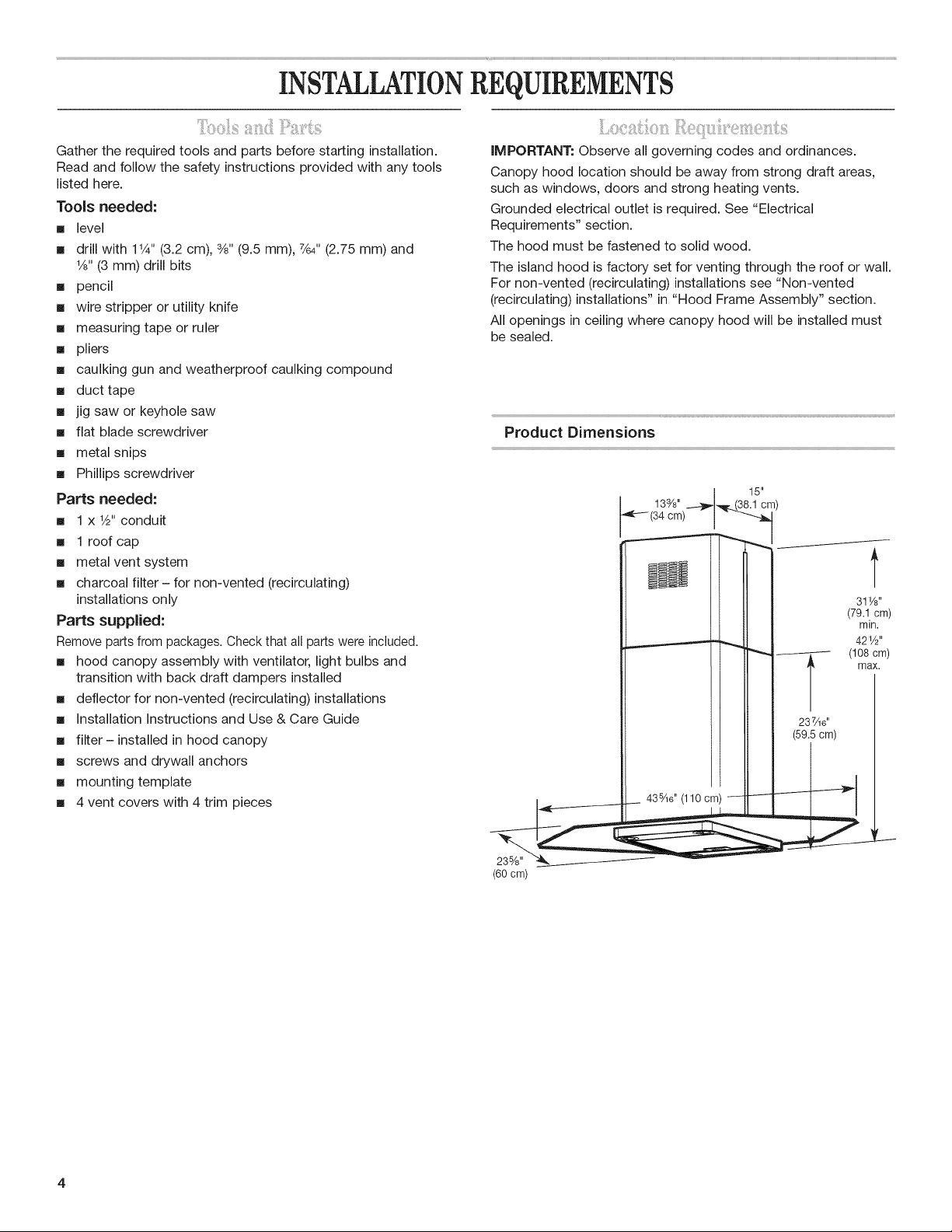
Product Dimensions
133/8' ---4_-_r.._(38.1 cm)
34cm) "
15"
_ii_i_i_;_;!!!_:f_:iit{i;;:::ii_ii!!!ill¸¸iii!!_i:!,',:i!!_,qi_i:i__:_ii_i'¸'{;!!{_;_i_:i_!!_:f_:iiii;_i!i;
Vent system must terminate to the outside.
Do not terminate the vent system in an attic or other enclosed
area.
Do not use 4" (10.2 cm) laundry-type wall caps.
Use metal vent only. Rigid metal vent is recommended. Do not
use plastic or metal foil vent.
For the most efficient and quiet operation:
m Use a straight run or as few elbows as possible.
m Use no more than three 90 ° elbows.
m Make sure there is a minimum of 24" (61 cm) of straight vent
between the elbows if more than one elbow is used.
m Do not install two elbows together.
m Use duct tape to seal all joints in the vent system.
m Use caulking to seal exterior wall or roof opening around
the cap.
Cold weather installations
An additional backdraft damper should be installed to minimize
backward cold air flow and a nonmetallic thermal break to
minimize conduction of outside temperatures as part of the vent
system. The damper should be on the cold air side of the thermal
break.
The break should be as close as possible to where the vent
system enters the heated portion of the house.
Make-up air
Local building codes may require the use of make-up air systems
when using ventilation systems greater than specified CFM of air
movement. The specified CFM varies from locale to locale.
Consult your HVAC professional for specific requirements in your
area.
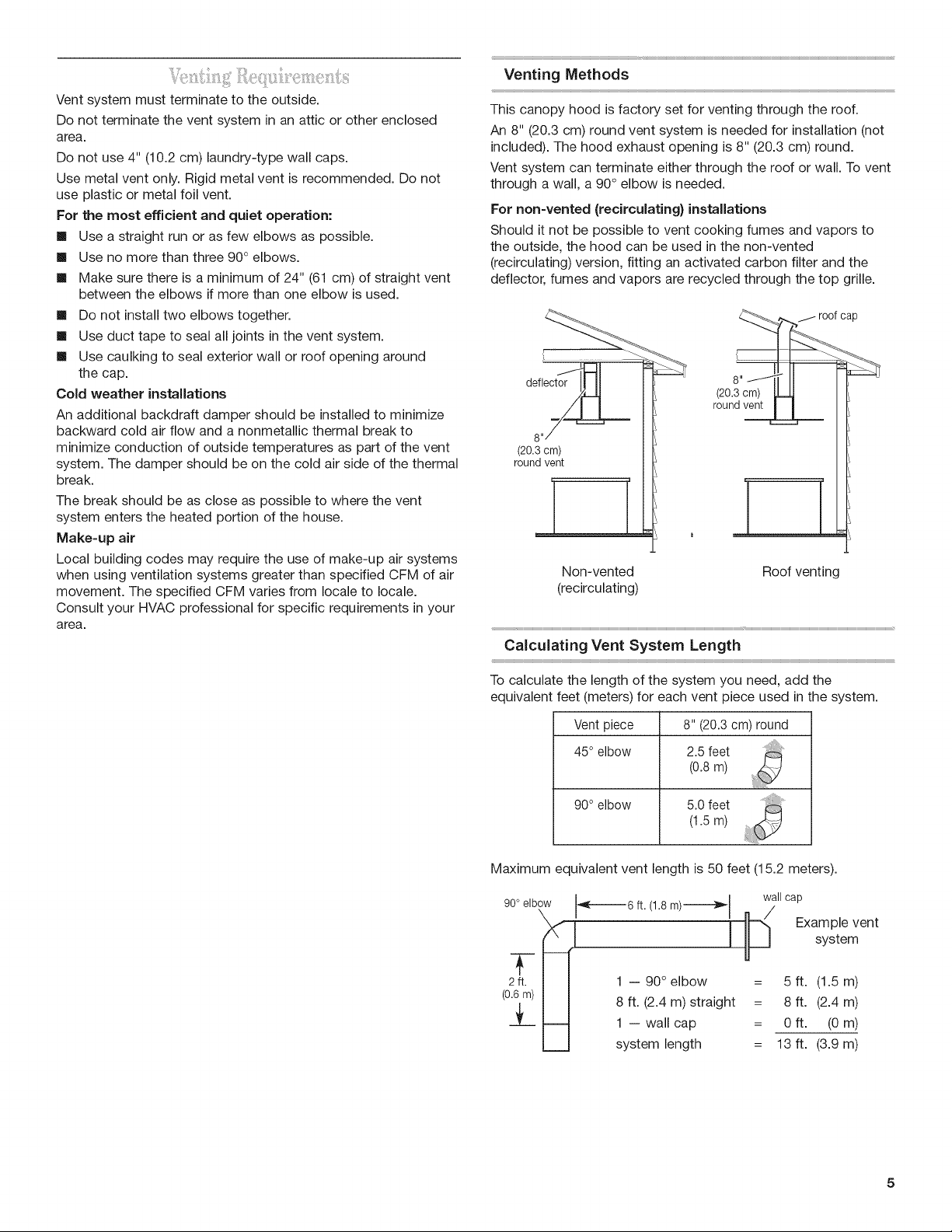
Venting Methods
This canopy hood is factory set for venting through the roof.
An 8" (20.3 cm) round vent system is needed for installation (not
included). The hood exhaust opening is 8" (20.3 cm) round.
Vent system can terminate either through the roof or wall. To vent
through a wall, a 90° elbow is needed.
For non-vented (recirculating) installations
Should it not be possible to vent cooking fumes and vapors to
the outside, the hood can be used in the non-vented
(recirculating) version, fitting an activated carbon filter and the
deflector, fumes and vapors are recycled through the top grille.
(20.3 cm)
round vent
Non-vented Roof venting
(recirculating)
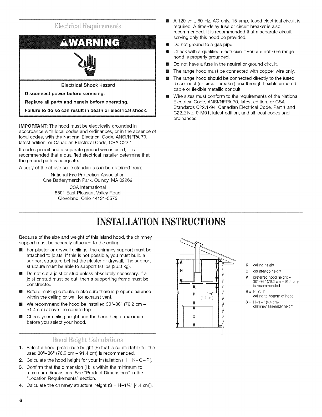
Calculating Vent System Length
To calculate the length of the system you need, add the
equivalent feet (meters) for each vent piece used in the system.
Vent piece 8" (20.3 cm) round
45° elbow 2.5 feet
(0.8 m)
90° elbow 5.0 feet
(1.5m)
Maximum equivalent vent length is 50 feet (15.2 meters).
90° elbow _(-_6 ft. (1.8 m)------_l wall cap
X I Ii--_ Example vent
__[l _ __J system
2ft. I I 1 -- 90° elbow = 5 ft. (1.5 m)
(u°.1."_-'' 'I I 8 ft. (2.4 m)straight = 8 ft. (2.4 m)
_Y__
L_J system length = 13 ft. (3.9 m)
1 --wallcap = Aft. (0m)
!iii!!iiilliil_ii:!!i__i:::_i::l_ii!:¸'il_i:i_i_i!iiiJ_:!!_i!il_i:!!!__i_:iii¸u:__ii_'eiiil:_iiiie_::ii_i::;_:i!ii
Electrical Shock Hazard
Disconnect power before servicing.
Replace all parts and panels before operating.
Failure to do so can result in death or electrical shock.
iMPORTANT: The hood must be electrically grounded in
accordance with local codes and ordinances, or in the absence of
local codes, with the National Electrical Code, ANSI/NFPA 70,
latest edition, or Canadian Electrical Code, CSA C22.1.
If codes permit and a separate ground wire is used, it is
recommended that a qualified electrical installer determine that
the ground path is adequate.
A copy of the above code standards can be obtained from:
National Fire Protection Association
One Batterymarch Park, Quincy, MA 02269
CSA International
8501 East Pleasant Valley Road
Cleveland, Ohio 44131-5575
m A 120-volt, 60-Hz, AC-only, 15-amp, fused electrical circuit is
required. A time-delay fuse or circuit breaker is also
recommended. It is recommended that a separate circuit
serving only this hood be provided.
m Do not ground to a gas pipe.
m Check with a qualified electrician if you are not sure range
hood is properly grounded.
m Do not have a fuse in the neutral or ground circuit.
m The range hood must be connected with copper wire only.
m The range hood should be connected directly to the fused
disconnect (or circuit breaker) box through flexible armored
cable or flexible metallic conduit.
m Wire sizes must conform to the requirements of the National
Electrical Code, ANSI/NFPA 70, latest edition, or CSA
Standards C22.1-94, Canadian Electrical Code, Part 1 and
C22.2 No. 0-M91, latest edition, and all local codes and
ordinances.
INSTALLATIONINSTRUCTIONS
Because of the size and weight of this island hood, the chimney
support must be securely attached to the ceiling.
m For plaster or drywall ceilings, the chimney support must be
attached to joists. If this is not possible, you must build a
support structure behind the plaster or drywall. The support
structure must be able to support 80 Ibs (36.3 kg).
m Do not cut a joist or stud unless absolutely necessary. If a
joist or stud must be cut, then a supporting frame must be
constructed.
m Before making cutouts, make sure there is proper clearance
within the ceiling or wall for exhaust vent.
m We recommend the hood be installed 30"-36" (76.2 cm -
91.4 cm) above the countertop.
m Check your ceiling height and the hood height maximum
before you select your hood.
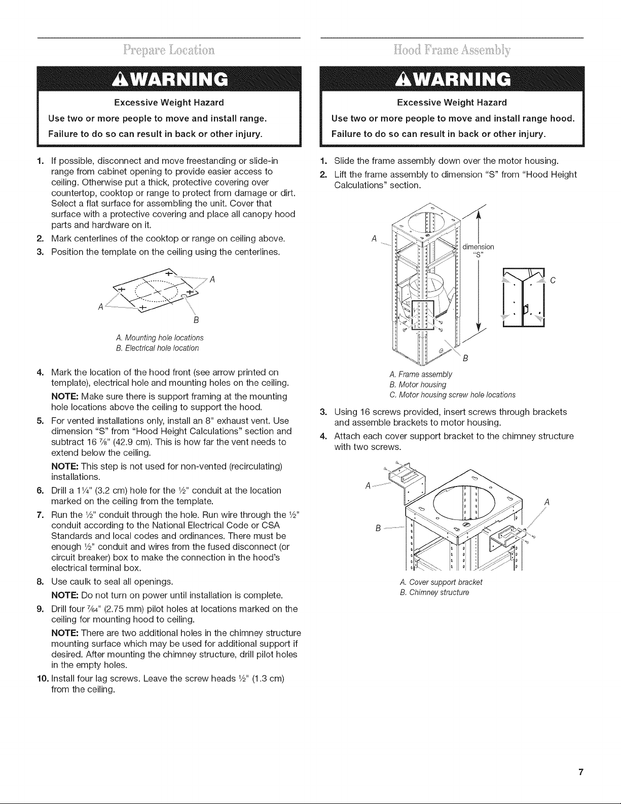
1. Select a hood preference height (P) that is comfortable for the
user. 30"-36" (76.2 cm - 91.4 cm) is recommended.
2. Calculate the hood height for your installation (H = K-C-P).
3. Confirm that the dimension (H) is within the minimum to
maximum dimensions. See "Product Dimensions" in the
"Location Requirements" section.
4. Calculate the chimney structure height (S = H-13/4'' [4.4 cm]).
K = ceiling height
C = countertop height
P = preferred hood height -
30"-36" (76.2 cm - 91.4 cm)
is recommended
H = K-C-P
ceiling to bottom of hood
S = H-13/4 '' (4.4 cm)
chimney assembly height
iiii!!i_::<_:!ii_!!i'l_i_i!!i_l_:!_:i_!!__!!i!i_!i!i;_!!_4!_i_:ii:i_iii:?¸
Excessive Weight Hazard
Use two or more people to move and install range.
Failure to do so can result in back or other injury.
1. If possible, disconnect and move freestanding or slide-in
range from cabinet opening to provide easier access to
ceiling. Otherwise put a thick, protective covering over
countertop, cooktop or range to protect from damage or dirt.
Select a flat surface for assembling the unit. Cover that
surface with a protective covering and place all canopy hood
parts and hardware on it.
2. Mark centerlines of the cooktop or range on ceiling above.
3. Position the template on the ceiling using the centerlines.
A
B
A. Mounting hole locations
B, Electrical hole location
4. Mark the location of the hood front (see arrow printed on
template), electrical hole and mounting holes on the ceiling.
NOTE: Make sure there is support framing at the mounting
hole locations above the ceiling to support the hood.
5. For vented installations only, install an 8" exhaust vent. Use
dimension "S" from "Hood Height Calculations" section and
subtract 16 7/8"(42.9 cm). This is how far the vent needs to
extend below the ceiling.
NOTE: This step is not used for non-vented (recirculating)
installations.
6. Drill a 11/4"(3.2 cm) hole for the 1/8"conduit at the location
marked on the ceiling from the template.
7. Run the 1/2"conduit through the hole. Run wire through the 1/8"
conduit according to the National Electrical Code or CSA
Standards and local codes and ordinances. There must be
enough 1/2"conduit and wires from the fused disconnect (or
circuit breaker) box to make the connection in the hood's
electrical terminal box.
8. Use caulk to seal all openings.
NOTE: Do not turn on power until installation is complete.
9. Drill four %4" (2.75 mm) pilot holes at locations marked on the
ceiling for mounting hood to ceiling.
NOTE: There are two additional holes in the chimney structure
mounting surface which may be used for additional support if
desired. After mounting the chimney structure, drill pilot holes
in the empty holes.
10. Install four lag screws. Leave the screw heads 1/8"(1.3 cm)
from the ceiling.
Excessive Weight Hazard
Use two or more people to move and install range hood.
Failure to do so can result in back or other injury.
1. Slide the frame assembly down over the motor housing.
2. Lift the frame assembly to dimension "S" from "Hood Height
Calculations" section.
A
dimension
"S"
=
C
Lo J_
_ B
A.Frameassembly
B.Motorhousing
C.Motorhousingscrewholelocations
3. Using 16 screws provided, insert screws through brackets
and assemble brackets to motor housing.
4. Attach each cover support bracket to the chimney structure
with two screws.
A
s _
B
A. Cover support bracket
B, Chimney structure
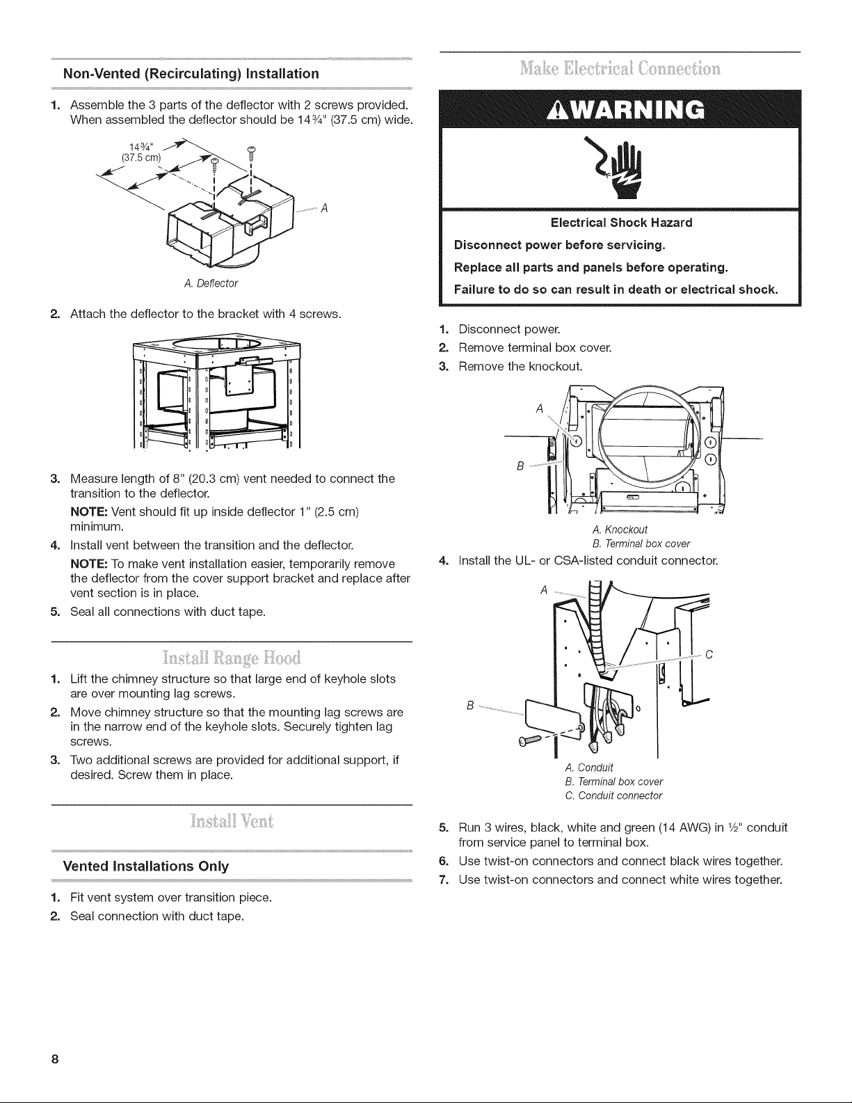
Non-Vented (Recirculating) installation
1. Assemble the 3 parts of the deflector with 2 screws provided.
When assembled the deflector should be 143/4'' (37.5 cm) wide.
143/4'' _ @
(37.5 cm) _o--_..
...............
A.Deflector
2= Attach the deflector to the bracket with 4 screws.
Electrical Shock Hazard
Disconnect power before servicing.
Replace all parts and panels before operating.
Failure to do so can result in death or electrical shock.
1. Disconnect power.
2. Remove terminal box cover.
3. Remove the knockout.
3. Measure length of 8" (20.3 cm) vent needed to connect the
transition to the deflector.
NOTE: Vent should fit up inside deflector 1" (2.5 cm)
minimum.
4. Install vent between the transition and the deflector.
NOTE: To make vent installation easier, temporarily remove
the deflector from the cover support bracket and replace after
vent section is in place.
5. Seal all connections with duct tape.
1. Lift the chimney structure so that large end of keyhole slots
are over mounting lag screws.
2. Move chimney structure so that the mounting lag screws are
in the narrow end of the keyhole slots. Securely tighten lag
screws.
3. Two additional screws are provided for additional support, if
desired. Screw them in place.
Vented Installations Only
1. Fit vent system over transition piece.
2. Seal connection with duct tape.
A, Knockout
B, Terminalbox cover
4=
Install the UL- or CSA-listed conduit connector.
B
A, Conduit
B, Terminal box cover
C, Conduit connector
5. Run 3 wires, black, white and green (14 AWG) in l&. conduit
from service panel to terminal box.
6. Use twist-on connectors and connect black wires together.
7. Use twist-on connectors and connect white wires together.

Electrical Shock Hazard
Electrically ground blower.
Connect ground wire to green and yellow ground wire
in terminal box.
Failure to do so can result in death or electrical shock.
5=
Connect lamp and control panels cable connectors to the
blower motor connectors.
A
8. Use twist-on connectors and connect green or bare wire with
yellow-green wire.
9o Replace terminal box cover.
10. Check all light bulbs to make sure they are secure intheir
sockets.
11. Reconnect power.
1=
Insert 3 screws on the bottom of the chimney structure (in
corresponding position to the keyhole slots on the hood
canopy).
A
A, Three screws
2. Lift hood canopy so that the large end of the keyhole slots are
over the 3 screws on the bottom of the chimney structure.
3. Push the hood canopy so that the 3 screws are in the narrow
end of the keyhole slots. Securely tighten the screws.
4. Install the remaining 9 screws and securely tighten.
A. Control panel connection
B. Lamp connection
6. Check lights and blower operation. See "Use and Care Guide"
section.
If hood does not operate:
m Check that the circuit breaker is not tripped or house fuse
blown.
m Disconnect power. Check that wiring is correct.
7. For non-vented (recirculating) installations, install the charcoal
filter. See "Use and Care Guide" section.
Install Vent Covers
1. Insert captive nuts on the inside of the vent covers at all 14
rectangular hole locations.
2. Place the upper vent covers around the chimney structure so
that the vent slots on the front cover face the same direction
as the control panel.
.°. _,, ....... "%%°%
° _ o
Front
A. Upperventcovers
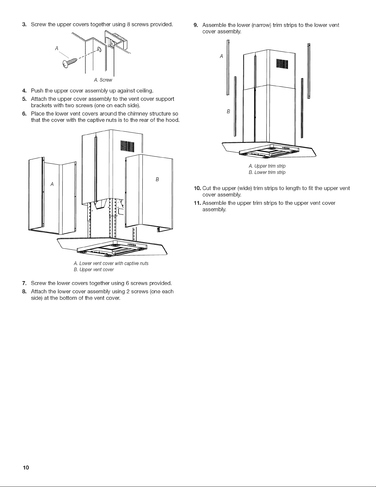
3. Screwtheuppercoverstogetherusing8screwsprovided. 9. Assemblethelower(narrow)trimstripstothelowervent
coverassembly.
A
A f I
A. Screw
4. Push the upper cover assembly up against ceiling.
5. Attach the upper cover assembly to the vent cover support
brackets with two screws (one on each side).
6. Place the lower vent covers around the chimney structure so
that the cover with the captive nuts is to the rear of the hood.
A. Upper trim strip
B. Lower trim strip
10. Cut the upper (wide) trim strips to length to fit the upper vent
cover assembly.
11. Assemble the upper trim strips to the upper vent cover
assembly.
A. Lower vent cover with captive nuts
B. Upper vent cover
7. Screw the lower covers together using 6 screws provided.
8. Attach the lower cover assembly using 2 screws (one each
side) at the bottom of the vent cover.
10
 Loading...