

Page 1
INSTALLATIONINSTRUCTIONS
30" (76.2 CM) GAS BUILT-INCOOKTOP
INSTRUCTIONS D'INSTALLATION .
DE LATABLEDE CUISSON A GAZ ENCASTREEDE
30" (76,2 CM)
Table of Contents/Table des mati_res
COOKTOP SAFETY ..................................................................................... 1
INSTALLATION REQUIREMENTS ............................................................. 2
Tools and Parts ......................................................................................... 2
Location Requirements ............................................................................. 3
Electrical Requirements ............................................................................ 4
Gas Supply Requirements ........................................................................ 4
INSTALLATION INSTRUCTIONS ............................................................... 5
Prepare Cooktop ...................................................................................... 5
Install Cooktop .......................................................................................... 5
Make Gas Connection .............................................................................. 6
Complete Installation ................................................................................ 7
WIRING DIAGRAM ...................................................................................... 8
SI_CURITI_ DE LA TABLE DE CUISSON ................................................... 9
EXIGENCES D'INSTALLATION ................................................................ 10
Outillage et pieces .................................................................................. 10
Exigences d 'emplacement ..................................................................... 10
Sp6cifications 61ectriques ....................................................................... 11
Specifications de I'alimentation en gaz .................................................. 12
INSTRUCTIONS D'INSTALLATION ......................................................... 13
Pr6paration de la table de cuisson ......................................................... 13
Installation de la table de cuisson .......................................................... 13
Raccordement au gaz ............................................................................ 14
Achever I'installation ............................................................................... 15
SCHleMAS DE CABLAGE ......................................................................... 16
COOKTOP SAFETY
Your safety and the safety of others are very important.
We have provided many important safety messages in this manual and on your appliance. Always read and obey all safety
messages.
This is the safety alert symbol.
This symbol alerts you to potential hazards that can kill or hurt you and others.
All safety messages will follow the safety alert symbol and either the word "DANGER" or "WARNING."
These words mean:
You can be killed or seriously injured if you don't immediately
follow instructions.
You can be killed or seriously injured if you don't follow
instructions.
All safety messages will tell you what the potential hazard is, tell you how to reduce the chance of injury, and tell you what can
happen if the instructions are not followed.
iMPORTANT:
installer: Leave installation instructions with the homeowner.
Homeowner: Keep installation instructions for future reference.
iMPORTANT :
Jnstallateur : Remettre les instructions d'installation au propri6taire.
Propri6taire : Conserver les instructions d'installation pour r6f6rence ult6rieure.
501910200427
Page 2
WARNING: If the information in this manual is not followed exactly, a fire or explosion
may result causing property damage, personal injury or death.
- Do not store or use gasoline or other flammable vapors and liquids in the vicinity of this
or any other appliance.
- WHAT TO DO IF YOU SMELL GAS:
• Do not try to light any appliance.
• Do not touch any electrical switch.
• Do not use any phone in your building.
• Immediately call your gas supplier from a neighbor's phone. Follow the gas supplier's
instructions.
• If you cannot reach your gas supplier, call the fire department.
- Installation and service must be performed by a qualified installer, service agency or
the gas supplier,
WARNING: Gas leaks cannot always be detected by smell.
Gas suppliers recommend that you use a gas detector approved by UL or CSA.
For more information, contact your gas supplier.
If a gas leak is detected, follow the "What to do if you smell gas" instructions.
In the State of Massachusetts, the following installation instructions apply:
• Installations and repairs must be performed by a qualified or licensed contractor, plumber, or gasfitter qualified or licensed by
the State of Massachusetts.
• If using a ball valve, it shall be a T-handle type.
• A flexible gas connector, when used, must not exceed 3 feet.
INSTALLATIONREQUIREMENTS
t'OOSc_...........
Gatherthe required tools and parts before starting installation.
Tools needed
• Tape measure • Phillips screwdriver
• Flat-blade screwdriver • Marker or pencil
• 15/le"combination wrench • Pipe-joint compound
• Pipe wrench
• Pliers • Noncorrosive leak-detection
• Level
resistant to LP gas
solution
Parts supplied
• Gas pressure regulator
• Burner grates (3)
• Burner caps (4)
• Clamping brackets (4)
• 1" (2.5 cm) clamping screws (4)
• Foam strip
Parts needed
Check local codes and consult gas supplier. Check existing gas
supply and electrical supply. See "Electrical Requirements" and
"Gas Supply Requirements" sections.
2
Page 3
IMPORTANT: Observe all governing codes and ordinances. Do
not obstruct flow of combustion and ventilation air.
It is the installer's responsibility to comply with installation
clearances specified on the model/serial rating plate. The
model/serial rating plate is located on the underside of the
cooktop burner box.
f ........................................................................................
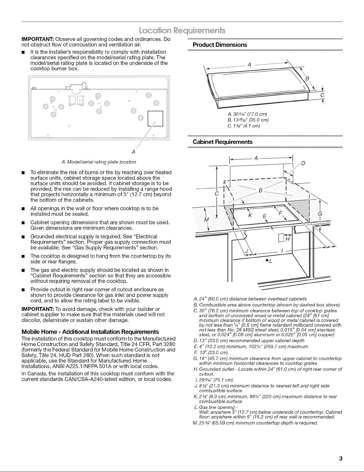
Product Dimensions
A
o
o
o ,,,/_
/
/
A
A. Model/serial rating plate location
To eliminate the risk of burns or fire by reaching over heated
surface units, cabinet storage space located above the
surface units should be avoided. If cabinet storage is to be
provided, the risk can be reduced by installing a range hood
that projects horizontally a minimum of 5" (12.7 cm) beyond
the bottom of the cabinets.
All openings in the wall or floor where cooktop is to be
installed must be sealed.
Cabinet opening dimensions that are shown must be used.
Given dimensions are minimum clearances.
Grounded electrical supply is required. See "Electrical
Requirements" section. Proper gas supply connection must
be available. See "Gas Supply Requirements" section.
The cooktop is designed to hang from the countertop by its
side or rear flanges.
The gas and electric supply should be located as shown in
"Cabinet Requirements" section so that they are accessible
without requiring removal of the cooktop.
Provide cutout in right rear corner of cutout enclosure as
shown to provide clearance for gas inlet and power supply
cord, and to allow the rating label to be visible.
IMPORTANT: To avoid damage, check with your builder or
cabinet supplier to make sure that the materials used will not
discolor, delaminate or sustain other damage.
Mobile Home - Additional Installation Requirements
The installation of this cooktop must conform to the Manufactured
Home Construction and Safety Standard, Title 24 CFR, Part 3280
(formerly the Federal Standard for Mobile Home Construction and
Safety, Title 24, HUD Part 280). When such standard is not
applicable, use the Standard for Manufactured Home
Installations, ANSI A225.1/NFPA 501A or with local codes.
In Canada, the installation of this cooktop must conform with the
current standards CAN/CSA-A240-1atest edition, or local codes.
C
A. 30_" (77.0 cm)
B. 132_2 '' (35.0 cm)
C. 1_" (4.1cm)
Cabinet Requirements
C
G
M
A. 24" (60.0 cm) distance between overhead cabinets
B. Combustible area above countertop (shown by dashed box above)
C. 30" (76.2 cm) minimum clearance between top of cooktop grates
and bottom of uncovered wood or metal cabinet (24" [61 cm]
minimum clearance if bottom of wood or metal cabinet is covered
by not less than 1/4"[0.6 cm] flame retardant millboard covered with
not less than No. 28 MSG sheet steel, 0.015" [0.04 cm] stainless
steel, or 0.024" [0.06 cm] aluminum or 0.020" [0.05 cm] copper)
D. 13" (33.0 cm) recommended upper cabinet depth
E.4" (10.2 cm) minimum, 102¼" (259.7 cm) maximum
F. 13" (33.0 cm)
G. 18" (45.7 cm) minimum clearance from upper cabinet to countertop
within minimum horizontal clearances to cooktop grates
H. Grounded outlet - Locate within 24" (61.0 cm) of right rear corner of
cutout.
I.29 _" (75.1 cm)
J. 8_" (21.3 cm) minimum distance to nearest left and right side
combustible surface
K. 2_" (6.0 cm) minimum, 86¼" (220 cm) maximum distance to rear
combustible surface
L. Gas line opening -
Waft: anywhere 5" (12. 7 cm) below underside of countertop. Cabinet
floor: anywhere within 6" (15.2 cm) of rear wall is recommended.
M. 25 _" (65.09 cm) minimum countertop depth is required.
Page 4
NOTES: After making the countertop cutout, some installations
may require notching down the base cabinet side walls to clear
the burner box. Toavoid this modification, use a base cabinet with
sidewalls wider than the cutout.
If cabinet has a drawer, a 4" (10.2 cm) depth clearance from the
countertop to the top of the drawer (or other obstruction) in base
cabinet is required. The drawer depth may need to be shortened
to avoid interfering with the regulator.
IMPORTANT: If installing a range hood or microwave hood
combination above the range, follow the range hood or
microwave hood combination installation instructions for
dimensional clearances above the cooktop surface.
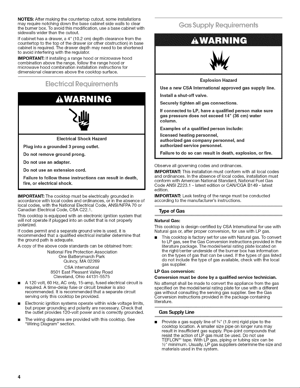
Electrical Shock Hazard
Plug into a grounded 3 prong outlet.
Do not remove ground prong.
Do not use an adapter.
Do not use an extension cord.
Failure to follow these instructions can result in death,
fire, or electrical shock.
IMPORTANT: The cooktop must be electrically grounded in
accordance with local codes and ordinances, or in the absence of
local codes, with the National Electrical Code, ANSI/NFPA 70 or
Canadian Electrical Code, CSA C22.1.
This cooktop is equipped with an electronic ignition system that
will not operate if plugged into an outlet that is not properly
polarized.
If codes permit and a separate ground wire is used, it is
recommended that a qualified electrical installer determine that
the ground path is adequate.
A copy of the above code standards can be obtained from:
National Fire Protection Association
One Batterymarch Park
Quincy, MA 02269
CSA International
8501 East Pleasant Valley Road
Cleveland, Ohio 44131-5575
• A 120 volt, 60 Hz, AC only, 15-amp, fused electrical circuit is
required. A time-delay fuse or circuit breaker is also
recommended. It is recommended that a separate circuit
serving only this cooktop be provided.
• Electronic ignition systems operate within wide voltage limits,
but proper grounding and polarity are necessary. Check that
the outlet provides 120-volt power and is correctly grounded.
• The wiring diagrams are provided with this cooktop. See
"Wiring Diagram" section.
Explosion Hazard
Use a new CSA International approved gas supply line.
Install a shut-off valve.
Securely tighten all gas connections.
if connected to LP, have a qualified person make sure
gas pressure does not exceed 14" (36 cm) water
column.
Examples of a qualified person include:
licensed heating personnel,
authorized gas company personnel, and
authorized service personnel.
Failure to do so can result in death, explosion, or fire.
Observe all governing codes and ordinances.
IMPORTANT: This installation must conform with all local codes
and ordinances. In the absence of local codes, installation must
conform with American National Standard, National Fuel Gas
Code ANSI Z223.1 - latest edition or CAN/CGA B149 - latest
edition.
IMPORTANT: Leak testing of the range must be conducted
according to the manufacturer's instructions.
Type of Gas
Natural Gas:
This cooktop is design-certified by CSA International for use with
Natural gas or, after proper conversion, for use with LP gas.
• This cooktop is factory set for use with Natural gas. To convert
to LP gas, see the Gas Conversion instructions provided inthe
literature package. The model/serial rating plate located on
the right/center underside of the burner box has information
on the types of gas that can be used. If the types of gas listed
do not include the type of gas available, check with the local
gas supplier.
LP Gas conversion:
Conversion must be done by a qualified service technician.
No attempt shall be made to convert the appliance from the gas
specified on the model/serial rating plate for use with a different
gas without consulting the serving gas supplier. See the Gas
Conversion instructions provided in the package containing
literature.
Gas Supply Line
Provide a gas supply line of 3/4"(1.9 cm) rigid pipe to the
cooktop location. A smaller size pipe on longer runs may
result in insufficient gas supply. Pipe-joint compounds that
resist the action of LP gas must be used. Do not use
TEFLON ®ttape. With LP gas, piping or tubing size can be
1/2"minimum. Usually, LP gas suppliers determine the size and
materials used in the system.
Page 5
Flexible metal appliance connector:
• If local codes permit, use a 1/2"or 3/4"I.D. flexible stainless
steel tubing gas connector, designed by CSA to connect
the cooktop to the rigid gas supply line.
• A 3/8"male pipe thread is needed for connection to the
female pipe threads of the inlet to the appliance pressure
regulator.
• Do not kink or damage the flexible metal tubing when
moving the cooktop.
Rigid pipe connection:
The rigid pipe connection requires a combination of pipe
fittings to obtain an in-line connection to the cooktop. The
rigid pipe must be level with the cooktop connection. All
strains must be removed from the supply and fuel lines so
cooktop will be level and in line.
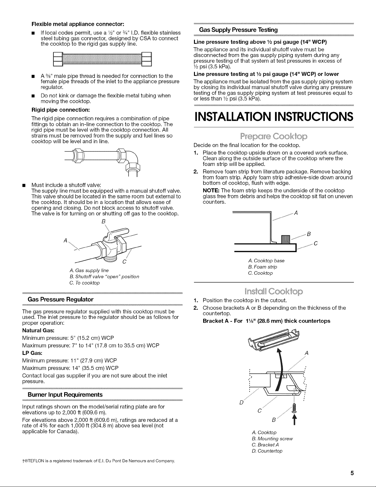
Must include a shutoff valve:
The supply line must be equipped with a manual shutoff valve.
This valve should be located in the same room but external to
the cooktop. It should be in a location that allows ease of
opening and closing. Do not block access to shutoff valve.
The valve is for turning on or shutting off gas to the cooktop.
B
Gas Supply Pressure Testing
Line pressure testing above 1/2psi gauge (14" WCP)
The appliance and its individual shutoff valve must be
disconnected from the gas supply piping system during any
pressure testing of that system at test pressures in excess of
1/2psi (3.5 kPa).
Line pressure testing at 1/2psi gauge (14" WOP) or lower
The appliance must be isolated from the gas supply piping system
by closing its individual manual shutoff valve during any pressure
testing of the gas supply piping system at test pressures equal to
or less than 1/2psi (3.5 kPa).
INSTALLATIONINSTRUCTIONS
,....,,.,,......,,..,,,_JO0/{ O©
Decide on the final location for the cooktop.
1. Place the cooktop upside down on a covered work surface.
Glean along the outside surface of the cooktop where the
foam strip will be applied.
2. Remove foam strip from literature package. Remove backing
from foam strip. Apply foam strip adhesive-side down around
bottom of cooktop, flush with edge.
NOTE: The foam strip keeps the underside of the cooktop
glass free from debris and helps the cooktop sit flat on uneven
counters.
"%" 7
A. Gas supply line
B. Shutoff valve "open" position
C. To cooktop
Gas Pressure Regulator
The gas pressure regulator supplied with this cooktop must be
used. The inlet pressure to the regulator should be as follows for
proper operation:
Natural Gas:
Minimum pressure: 5" (15.2 cm) WCP
Maximum pressure: 7" to 14" (17.8 cm to 35.5 cm) WCP
LP Gas:
Minimum pressure: 11" (27.9 cm) WCP
Maximum pressure: 14" (35.5 cm) WCP
Contact local gas supplier if you are not sure about the inlet
pressure.
Burner Input Requirements
Input ratings shown on the model/serial rating plate are for
elevations up to 2,000 ft (609.6 m).
For elevations above 2,000 ff (609.6 m), ratings are reduced at a
rate of 4% for each 1,000 ft (304.8 m) above sea level (not
applicable for Canada).
1-®TEFLON is a registered trademark of E.I. Du Pont De Nemours and Company.
A. Cooktop base
B. Foam strip
C. Cooktop
nsI s Coo < o
1.
Position the cooktop in the cutout.
2.
Choose brackets A or B depending on the thickness of the
countertop.
Bracket A - For 1%" (28.6 ram) thick countertops
D / .......
C ....//'/_
t
A. Cooktop
B. Mounting screw
C. Bracket A
D. Countertop
Page 6

Bracket B - For 11/2'' (38.0 mm) thick countertops
_A
D iS _ii#,!Y_ .... _///,
g '/id_
A. Cooktop
B. Mounting screw
C. Bracket B
D. Countertop
3.
Secure the cooktop. Attach mounting brackets at the hole
locations (A)using the screws supplied.
View of underside of cooktop
A A
Explosion Hazard
Use a new CSA International approved gas supply line.
install a shut=off valve.
Securely tighten all gas connections.
if connected to LP, have a qualified person make sure
gas pressure does not exceed 14" (36 cm) water
column.
Examples of a qualified person include:
licensed heating personnel,
authorized gas company personnel, and
authorized service personnel.
Failure to do so can result in death, explosion, or fire.
To Assemble Pressure Regulator:
1. Using 2 or more people, stand the cooktop on its side or back.
2. Connect the flexible stainless steel connector to the pressure
regulator using a _/2"male pipe thread adapter and nipple.
A combination of pipe fittings must be used to connect the
cooktop to the existing gas line. Shown following is a typical
connection. Your connection may be different, according to
the supply line type, size and location.
A
B
3. Install the pressure regulator with the arrow pointing up
toward the bottom of the cooktop base and in a position
A. Mounting hole locations
B. Front of cooktop
where you can reach the regulator cap.
A
A. Access cap
B. Rear of cooktop
C. Gas pressure regulator
D. Up arrow. Regulator must be installed with
arrow pointing up to cooktop bottom.
IMPORTANT: All connections must be wrench-tightened. Do
not make connections to the gas regulator too tight. Making
the connections too tight may crack the regulator and cause a
gas leak. Do not allow the regulator to turn on the pipe when
tightening fittings.
Use only pipe-joint compound made for use with Natural and LP
gas.
Do not use TEFLON ®tape. You will need to determine the fittings
required depending on your installation.
6
Page 7

Typical flexible connection
1. Apply pipe-joint compound made for use with LP gas to the
smaller thread ends of the flexible connector adapters (see G
in the following illustration).
2. Attach 1 adapter and nipple to the gas pressure regulator and
the other adapter and nipple to the gas shutoff valve. Tighten
both adapters and nipples.
3. Use a 1%e"combination wrench and pliers to attach the
flexible connector to the adapters. Check that connector is
not kinked.
A. %" nipple
B. %" adapter
C. Flexible connector
D. Y2"nipple
E. Gas pressure regulator
F 7/2"adapter
G. Use pipe-joint compound.
H. Manual gas shutoff valve
Complete Connection
1. Open the manual shutoff valve in the gas supply line. The
valve is open when the handle is parallel to the gas pipe.
A. Closed valve
B. Open valve
2.
Test all connections by brushing on an approved noncorrosive
leak-detection solution. Bubbles will show a leak. Correct any
leak found.
3.
Remove surface burner caps and grates from parts package.
Align notches in burner caps with pins in burner base. Burner
caps should be level when properly positioned. If burner caps
are not properly positioned, surface burners will not light.
Place burner grates over burners and caps.
B C
Electrical Shock Hazard
Plug into a grounded 3 prong outlet.
Do not remove ground prong.
Do not use an adapter.
Do not use an extension cord.
Failure to follow these instructions can result in death,
fire, or electrical shock.
4. Plug into a grounded 3 prong outlet.
Electronic Ignition System
Initial lighting and gas flame adjustments
Surface burners use electronic igniters in place of standing pilots.
When the cooktop control knob is turned to the "LITE" position,
the system creates a spark to light the burner. This sparking
continues, as long as the control knob is pushed in.
Check Operation of Surface Burners
1. Push in and turn the surface burners control knobs to the
"LITE" position.
The surface burner flame should light within 10 seconds. The
first time a surface burner is lit it may take longer than
10 seconds to light because of air in the gas line.
2. Check the flame on "HI" for a blue color. It should be clean
and soft in character. No yellow tip, blowing or lifting of flame
should occur. Occasional orange flashes are normal and
reflect different elements in the air or gas.
3. Repeat at "LO" position.
4. After verifying the proper burner operation, turn the control
knobs to "OFR"
If burners do not light properly:
• Turn surface burner control knob to the "OFF" position.
Check that the power supply cord is plugged in and the circuit
breaker has not tripped or the fuse blown.
Check that the gas shutoff valves are set to the "open"
position.
Check that burner caps are properly positioned on burner
bases.
Recheck operation of surface burners. If a burner does not light at
this point, turn control knobs to "Off" and contact your dealer or
authorized service company for assistance.
A. Igniter electrode
B. Burner cap
C. Burner base
Page 8

Adjust Flame Height
The surface burner "low" flame should be a steady blue flame
approximately 1¼.(0.64 cm) high.
A
A. Low flame
B.High flame
If the "low" flame needs to be adjusted:
The flame can be adjusted using the adjustment screws
underneath the control knob.
1. Set the burner flame to "LO."
2. Remove the control knob.
3. Tighten screw to reduce flame height. Loosen screw to
increase flame height.
4. Replace the control knob.
5. Test the flame by turning the control from "LO" to "HI,"
checking the flame at each setting.
A.Adjustment screw
WIRING DIAGRAM
The power cord on this cooktop is equipped with a 3 prong (grounding) plug which mates with standard 3 prong (grounding) wall
receptacles.
Caution: Label all wires prior to disconnection when servicing controls. Wiring errors can cause improper and
dangerous operation. Verify proper operation after servicing.
120 VAC 60Hz
Plug
Line Neutral
1/4"Wide Blade sA6"WideBlade
Ground
RoundBlade
1 Phase
15 or 20 Amp
W
G or G/Y
BK
: Power Supply
Valve
Spark Module
Switches
BK
/
BK
/__
J__
G
(1)PLCS
SwitchesOnValves
Electriccircuit closed when
knobis rotated550to 950
counterclockwisefromOff
BR
(3) PLCS
YOR ___
igniter
E,ectrodes ___ _
8
Page 9

SECURITEDELA TABLEDECUlSSON
Votre securite et celle des autres est tres importante.
Nous donnons de nombreux messages de s_curit_ importants dans ce manuel et sur votre appareil m_nager. Assurez-vous de
toujours lire tousles messages de s_curit_ et de vous y conformer.
Ce symbole d'alerte de s_curit_ vous signale les dangers potentiels de d_c_s et de blessures graves &vous
et & d'autres.
Voici le symbole d'alerte de s_curit&
Tousles messages de s_curit_ suivront le symbole d'alerte de s_curit_ et le mot "DANGER" ou
"AVERTISSEMENT". Ces mots signifient •
Risque possible de d_cbs ou de blessure grave si vous ne
suivez pas imm_diatement les instructions.
Risque possible de d_cbs ou de blessure grave si vous
ne suivez pas les instructions.
Tousles messages de s_curit_ vous diront quel est le danger potentiel et vous disent comment r_duire le risque de blessure et
ce qui peut se produire en cas de non-respect des instructions.
AVERTISSEMENT •Si les renseignements dans ce manuel ne sont pas exactement
observes, un incendie ou une explosion peut survenir, causant des dommages au
produit, des blessures ou un deces.
- Ne pas entreposer ni utiliser de I'essence ou d'autres vapeurs ou liquides inflammables
proximite de cet appareil ou de tout autre appareil electromenager.
-QUE FAIRE DANS LE CAS D'UNE ODEUR DE GAZ :
• Ne pas tenter d'allumer un appareil.
• Ne pas toucher a un commutateur electrique.
• Ne pas utiliser le telephone se trouvant sur les lieux.
• Appeler immediatement le fournisseur de gaz a partir du telephone d'un voisin. Suivre
ses instructions.
• .&.defaut de joindre votre fournisseur de gaz, appeler les pompiers.
- L'installation et I'entretien doivent _tre effectues par un installateur qualifie, une agence
de service ou le fournisseur de gaz.
AVERTISSEMENT : L'odorat ne permet pas toujours la detection d'une fuite de gaz.
Les distributeurs de gaz recommandent I'emploi d'un detecteur de gaz (homologation UL ou CSA).
Pour d'autre information, contacter le fournisseur de gaz local.
En cas de detection d'une fuite de gaz, executer les instructions "Que faire dans le cas d'une odeur de gaz".
Dans 1'12tatdu Massachusetts, les instructions d'installation suivantes sont applicables :
[] Les travaux d'installation et r_paration doivent 6tre executes par un plombier ou tuyauteur qualifi_ ou licenci_, ou par le
personnel qualifi_ d'une entreprise licenci_e par 1'12tatdu Massachusetts.
[] Si une vanne & boisseau sph_rique est utilis_e, elle doit comporter une manette "T".
[] Si un conduit de raccordement flexible est utilis_, sa Iongueur ne doit pas d_passer 3 pi.
Page 10

EXIGENCESD'INSTALLATION
Rassembler les outils et pi@ces n@cessaires avant de commencer
I'installation.
Outillage n_cessaire
• M_tre-ruban • Tournevis Phillips
• Tournevis a lame plate • Marqueur ou crayon
• Cle mixte de _5/le" • Compose d'etanch6it6 des
• Cle a tube
• Pince
• Niveau detection des fuites
Pi_ces fournies
• Detendeur
• Grilles de brQleur (3)
• Chapeaux de brQleur (4)
• Brides de fixation (4)
• Vis de fixation de 1" (2,5 cm) (4)
• Bande de mousse
Pi_ces n_cessaires
Verifier les codes Iocaux et consulter le fournisseur de gaz.
Verifier I'alimentation en gaz et I'alimentation electrique
existantes. Voir les sections "Specifications electriques" et
"Specifications de I'alimentation en gaz".
IMPORTANT : Observer les dispositions de tousles codes et
r_glements en vigueur. Ne pas obstruer le flux de combustion et la
ventilation.
C'est & I'installateur qu'incombe la responsabilite de respecter
les distances de separation specifi6es sur la plaque
signaletique de I'appareil. La plaque signaletique des numeros
de modele et de serie est situ6e sur la face inferieure de la
boite de brQleur de la table de cuisson.
/ ...........................................................................................
raccords filetes - resistant
au propane
• Solution non corrosive de
Respecter les dimensions indiqu6es pour la cavite
d'installation entre les placards. Ces dimensions tiennent
compte des valeurs minimales des degagements de
separation.
Une source d'electricit6 avec liaison & la terre est necessaire.
Voir la section "Specifications electriques". Une source de gaz
adequate doit _tre disponible. Voir la section "Specifications
de I'alimentation en gaz".
De par sa conception, la table de cuisson est suspendue sur
le plan de travail, par les rebords des c6tes ou de I'arriere.
Veiller & placer les sources de gaz et d'electricit6 selon les
indications de la section "Dimensions du placard", pour
qu'elles soient accessibles sans depose de la table de
cuisson.
Prevoir une ouverture dans I'angle arriere droit de I'enceinte
(voir I'illustration) pour le passage de la canalisation de gaz et
du c&ble d'alimentation electrique et pour que I'etiquette
signaletique soit visible.
IMPORTANT : Pour eviter tout dommage, consulter le
constructeur de la maison ou le fabricant des placards pour
determiner si les materiaux utilises peuvent subir un changement
de couleur, une destratification ou d'autres dommages.
R_sidence mobile - Sp6cifications additionnelles
respecter Iors de I'installation
L'installation de cette table de cuisson doit _tre conforme aux
dispositions de la norme Manufactured Home Construction and
Safety Standard, Title 24 CFR, Part 3280 (anciennement Federal
Standard for Mobile Home Construction and Safety, Title 24, HUD
Part 280). Lorsque cette norme n'est pas applicable, I'installation
doit satisfaire aux criteres de la norme Standard for Manufactured
Home Installations, ANSI A225.1/NFPA 501A ou aux dispositions
des codes Iocaux.
Au Canada, I'installation de cette table de cuisson doit satisfaire
aux stipulations de la version la plus recente de la norme CAN/
CSA-A240, ou des codes Iocaux en vigueur.
Dimensions du produit
¸ o
©°o ©
: __
A
A. Emplacement de la plaque signal_tique
Afin de supprimer le risque de brQlures ou d'incendie en se
penchant au-dessus des unites de surface chauffees, le
rangement en armoire doit _tre evit& Si le rangement en
armoire est envisage, le risque peut _tre reduit par
I'installation d'une hotte de cuisine operant horizontalement
sur un minimum de 5" (12,7 cm) au-del& du bas des armoires.
Toutes les ouvertures dans lemur ou le plancher de
I'emplacement d'installation de la table de cuisson doivent
_tre scellees.
10
A. 30_" (77,0 cm)
B. 132_ '' (35,0 cm)
C. 1_" (4,1 cm)
Page 11

Dimensions du placard
C
A. Distance de s_paration de 24" (60,0 cm) entre les placards muraux
B. Zone de matiere combustible au-dessus du plan de travail (espace
d_limit_ par des lignes pointill_es ci-dessus)
C. Distance de s_paration de 30" (76,2 cm) ou plus entre les grilles de
la table de cuisson et le fond d'un placard m_taflique ou de bois
non prot_g_ (distance de s_paration de 24" [61,0 cm] ou plus si le
fond du placard de m#tal ou de bois est prot_g# par une plaque de
¼" (0,6 cm) ou plus de mat_riau r_sistant aux flammes recouvert
d'une feuifle m_tallique d'_paisseur #gale ou sup_rieure _ calibre 28
pour I'acier, 0,015" [0,04 cm] pour I'acier inoxydable, ou 0,024"
[0,06 cm] pour I'aluminium ou 0,020" [0,05 cm] pour le cuivre)
D. Profondeur recommand_e des placards muraux 13" (33,0 cm)
E. 4" (10,2 cm) minimum, 102¼" (259, 7 cm) maximum)
F. 13" (33 cm)
G. Distance de s_paration de 18" (45, 7 cm) ou plus entre placards
muraux et plan de travail avec distance minimale de s_paration
horizontale pour les grifles de la table de cuisson
H. Prise de courant reli_e _ la terre - La situer _ moins de 24" (61,0 cm)
de I'angle arriere droit de I'ouverture d_coup_e.
I. 29 _" (75,1 cm)
J. Distance de s_paration de 8_" (21,3 cm) ou plus par rapport _ la
plus proche surface de mat_riau combustible _ gauche ou _ droite
K. Distance de s_paration de 86¼" (220 cm) maximum et de 2_"
(6 cm) minimum par rapport _ une surface de mat_riau combustible
I'arriere
L. Ouverture pour canafisation de gaz - mur : n'importe oh,
5" (12, 7 cm) au-dessous de la face inf_rieure du plan de travail.
Plancher du placard : n'importe oh, _ moins de 6" (15,2 cm) du mur
arriere (recommandation.)
M. Un plan de travail de profondeur de 25_" (65,09 cm) ou plus est
n_cessaire.
REMARQUES : Apr_s le decoupage de I'ouverture dans le plan
de travail, dans certaines configurations d'installation il sera
necessaire d'entailler les parois laterales du placard inferieur pour
le passage de la boite des brQleurs. Pour eviter cette modification,
utiliser un placard inferieur dont la largeur des parois laterales est
superieure a celle de I'ouverture decoupee.
Si le placard comporte un tiroir, on devra menager une distance
de separation de 4" (10,2 cm) entre le plan de travail et le sommet
du tiroir (ou autre obstruction) dans le placard inferieur. II pourra
etre necessaire de reduire la profondeur du tiroir pour eviter une
interference avec le detendeur.
IMPORTANT: En cas d'installation d'une hotte ou d'un ensemble
hotte/micro-ondes au-dessus de la cuisiniere, suivre les
instructions fournies avec la hotte concernant les dimensions de
degagement & respecter au-dessus de la surface de la table de
cuisson.
Risque de choc _lectrique
Brancher sur une prise a 3 alv_oles reli_e a la terre.
hie pas enlever la broche de liaison a la terre.
hie pas utiliser un adaptateur.
hie pas utiliser un c&ble de rallonge.
Le non=respect de ces instructions peut causer
un d_cbs, un incendie ou un choc _lectrique.
IMPORTANT : La table de cuisson doit etre correctement reliee
la terre en conformite avec les codes et reglements Iocaux en
vigueur, ou en I'absence de tels codes, avec le National Electrical
Code, ANSI/NFPA 70 ou le Code canadien des installations
electriques, CSA C22.1.
Cette table de cuisson est dotee d'un systeme d'allumage
electronique qui ne fonctionnera pas en cas de branchement dans
une prise qui n'est pas correctement polarisee.
Si les codes le permettent et si on utilise un conducteur distinct
de liaison & la terre, il est recommande qu'un electricien qualifie
verifie la qualite de la liaison & la terre.
Pour obtenir un exemplaire de la norme des codes ci-dessus,
contacter :
National Fire Protection Association
One Batterymarch Park
Quincy, MA 02269
CSA International
8501 East Pleasant Valley Road
Cleveland, OH 44131-5575
L'appareil doit etre alimente par un circuit de 120 V, CA
seulement, 60 Hz, 15 amperes, protege par fusible. On
recommande egalement d'utiliser un fusible ou un disjoncteur
temporis& II est recommande de raccorder la table de
cuisson sur un circuit distinct exclusif & cet appareil.
Les systemes d'allumage electronique fonctionnent avec des
limites de tension etendues, mais une liaison &la terre
correcte et une polarite appropriee sont necessaires. Verifier
que la prise fournit une alimentation de 120 V et qu'elle est
correctement reliee a la terre.
• Les schemas de c&blage sont fournis avec cette table de
cuisson. Voir la section "Schemas de c&blage".
11
Page 12

Risque d'explosion
Utiliser une canalisation neuve d'arriv_e de gaz
approuv_e par la CSA international.
Installer un robinet d'arr_t.
Bien setter chaque organe de connexion de la
canalisation de gaz.
En cas de connexion au gaz propane, demander a une
personne qualifi_e de s'assurer que la pression de gaz
ne d_passe pas 36 cm (14 po) de la colonne d'eau.
Par personne qualifi_e, on comprend :
le personnel autoris_ de chauffage,
le personnel autoris_ d'une compagnie de gaz, et
le personnel d'entretien autoris&
Le non=respect de ces instructions peut causer
un d_c_s, une explosion ou un incendie.
Observer les dispositions de tous les codes et r_glements en
vigueur.
IMPORTANT • L'installation doit satisfaire aux criteres de tousles
codes et r_glements Iocaux. En I'absence de code local,
I'installation doit satisfaire aux prescriptions de la plus recente
edition du code national en vigueur : National Fuel Gas Code
ANSI Z223.1 ou CAN/CGA B149.
IMPORTANT : Les tests de fuite de la table de cuisson doivent
_tre effectu6s selon les instructions du fabricant.
Canalisation de gaz
Installer une canalisation de gaz rigide de 34,,(1,9 cm) jusqu'&
I'emplacement d'installation de la table de cuisson. L'emploi
d'une canalisation de plus petit diam_tre ou plus Iongue peut
causer une deficience du debit d'alimentation. On doit utiliser
un compose d'etancheite des tuyauteries resistant a I'action
du gaz propane. Ne pas utiliser de ruban TEFLON% Pour
I'alimentation au propane, le diam_tre des canalisations doit
_tre de _/_"ou plus. Usuellement, le fournisseur de gaz
propane determine les materiaux & utiliser et le diam_tre
appropri&
Raccord m_tallique flexible :
Si les codes Iocaux le permettent, utiliser un connecteur
gaz flexible en acier inoxydable de _/_"ou %" de diam_tre
interne, con£supar CSA pour raccorder la table de cuisson
la canalisation rigide d'alimentation en gaz.
• Un raccord avec filetage m&le de 3/8"est necessaire pour
la connexion sur le raccord & filetage femelle & I'entree du
detendeur de la table de cuisson.
• Ne pas deformer/ecraser/endommager le tube metallique
flexible Iors d'un deplacement de la table de cuisson.
Raccordement par un ensemble rigide :
On doit utiliser une combinaison de raccords pour realiser un
raccordement rigide entre la table de cuisson et la
canalisation de gaz. Le tuyau rigide doit se trouver au m_me
niveau que le raccord de connexion de la table de cuisson. On
doit veiller & ne soumettre les sections de canalisation
d'alimentation &aucun effort de traction ou flexion pour que la
table de cuisson soit d'aplomb et correctement alignee.
Type de gaz
Gaz naturel :
La conception de cette table de cuisson a et6 homologuee par
CSA International pour I'alimentation au gaz naturel, ou pour
I'alimentation au propane apr_s conversion adequate.
• Cette table de cuisson a et6 configuree a I'usine pour
I'alimentation au gaz naturel. Pour effectuer la conversion
pour une alimentation au propane, voir les instructions de
conversion de gaz fournies dans le sachet de documentation.
La plaque signaletique des numeros de modele et de serie
situee sur la face inferieure (adroite/au centre) de la boite de
brQleur indique les types de gaz utilisables. Si le type de gaz
disponible n'est pas mentionne sur la plaque signaletique,
consulter le fournisseur local.
Conversion pour I'alimentation au propane :
L'op_ration de conversion dolt _tre ex_cut_e par un
technicien de r_paration qualifi&
Ne pas entreprendre de convertir la table de cuisson pour
I'utilisation d'un gaz different de celui indiqu_ sur la plaque
signaletique sans d'abord consulter le fournisseur de gaz. Voir les
instructions de conversion de gaz fournies dans le sachet de
documentation.
Robinet d'arr_t necessaire :
La canalisation d'alimentation doit comporter un robinet
d'arr_t manuel. Le robinet d'arr_t manuel doit _tre separe de
la table de cuisson, mais doit se trouver dans la m_me piece.
La canalisation doit se trouver en un endroit facilement
accessible pour les manceuvres d'ouverture/fermeture. Ne
pas entraver I'acces au robinet d'arr_t manuel. Le robinet
d'arr_t manuel est prevu pour ouvrir ou fermer I'alimentation
en gaz de la table de cuisson.
B
A. Canalisation de gaz
B. Robinet d'arr_t manuel - position d'ouverture
C. Vers table de cuisson
1-®TEFLON est une marque d_pos&e de E.I. Du Pont De Nemours et Compagnie
12
Page 13

D_tendeur
Le detendeur fourni avec cette table de cuisson doit _tre utilis& La
pression d'alimentation du detendeur doit _tre comme suit pour un
fonctionnement correct •
Gaz naturel :
Pression minimum • 5" (15,2 cm) (colonne d'eau)
Pression maximum •7" a 14" (17,8 cm & 35,5 cm) (colonne d'eau)
Gaz propane :
Pression minimum • 11" (27,9 cm) (colonne d'eau)
Pression maximum • 14" (35,5 cm) (colonne d'eau)
En cas d'incertitude quant & la pression d'alimentation & etablir,
contacter le fournisseur de gaz local.
Caract_ristiques d'alimentation du br_leur
Les debits thermiques indiques sur la plaque signaletique
correspondent & une altitude d'utilisation inferieure
2000 pi (609,6 m).
Lorsque I'appareil est utilise & une altitude superieure &
2000 pi (609,6 m), on doit reduire le debit thermique indique
de 4 % pour chaque tranche de 1000 pi (304,8 m) au-dessus
du niveau de lamer (non applicable au Canada).
Test de pressurisation de la canalisation de gaz
Pressurisation a une pression sup_rieure a 1/2Ib/po 2
(14" - colonne d'eau)
Lors de tout test de pressurisation de ce systeme a une pression
superieure &1/2Ib/po 2(3,5 kPa), on doit deconnecter la table de
cuisson et son robinet d'arr_t individuel de la canalisation de gaz.
Pressurisation a une pression de 1/2Ib/po 2
(14" - colonne d'eau) ou moins
Lors de tout test de pressurisation de la canalisation de gaz & une
pression egale ou inferieure & 1/2Ib/po2(3,5 kPa), on doit isoler la
table de cuisson de la canalisation de gaz par fermeture de son
robinet d'arr_t manuel individuel.
1=
Placer la table de cuisson dans I'ouverture.
2.
Choisir les supports A ou Ben fonction de I'epaisseur du plan
de travail.
Support A - Pour plans de travail de 1%" (28,6 mm)
d'_paisseur
D ............. ................ [ ':
C
t
A. Tablede cuisson
B. Visde montage
C.Bride A
D. Plan de travail
Support B - Pour plans de travail de 1W' (38,0 mm)
d'_paisseur
INSTRUCTIONS
D'INSTALLATION
Determiner I'emplacement final de la table de cuisson.
1. Placer la table de cuisson & I'envers sur une surface de travail
couverte. Nettoyer le long de la surface exterieure de la table
de cuisson &I'endroit oQ la bande de mousse doit _tre
appliquee.
2. Enlever la bande de mousse du sachet de documentation.
Retirer I'endos de la bande de mousse. Appliquer le c6te
adhesif de la bande de mousse autour du fond de la table de
cuisson, en affleurement avec le rebord.
REMARQUE : La bande de mousse protege la face inferieure
du verre de la table de cuisson des debris et I'aide & reposer &
plat sur des plans de travail irreguliers.
Ih@.......................
A. Base de la table de cuisson
B.Bande de mousse
C. Tablede cuisson
D" ""
A. Tablede cuisson
B. Visde montage
C.Support B
D.Plan de travail
3=
Immobiliser la table de cuisson. Fixer les supports de
montage a I'emplacement des trous (A) des brQleurs a I'aide
des vis fournies.
Vue de la face inf_rieure de la table de cuisson
A A
o
A B A
A. Emplacements des trous de montage
B. Avant de la table de cuisson
13
Page 14

Risque d'e×plosion
Utiiiser une canalisation neuve d'arriv_e de gaz
approuv_e par la CSA International.
installer un robinet d'arr_t.
Bien serrer chaque organe de conne×Jon de la
canalisation de gaz.
En cas de connexion au gaz propane, demander a une
personne qualifi_e de s'assurer que la pression de gaz
ne d_passe pas 36 cm (14 po) de la colonne d'eau.
Par personne qualJfi_e, on comprend :
le personnel autoris_ de chauffage,
le personnel autoris_ d'une compagnie de gaz, et
le personnel d'entretien autoris&
Le non=respect de ces instructions peut causer
un d_c_s, une explosion ou un incendie.
Assemblage du d_tendeur :
1. Placer la table de cuisson en appui sur le c6te ou la face
arriere; avec I'aide de deux personnes ou plus.
2. Connecter le raccord flexible d'acier inoxydable au detendeur
- utiliser un raccord droit et un raccord d'adaptation
comportant un filetage male de 1/2"(NPT).
On doit utiliser une combinaison de raccords de tuyauterie
pour raccorder la table de cuisson & I'alimentation en gaz
existante. On voit ci-dessous une illustration d'un
raccordement typique. Le raccordement peut varier, selon le
type, la dimension et I'emplacement du conduit
d'alimentation.
3. Orienter la fleche du detendeur vers le haut, vers le fond de la
base de la table de cuisson et orienter le detendeur de telle
maniere que le chapeau du detendeur soit accessible.
.............................................g
IMPORTANT : Tous lesraccords doivent @trebien serres
I'aide d'une cl& Ne pas serrerexcessivement lesconnexions
au detendeur. Un serrageexcessif pourrait provoquer une
fissuration du detendeur et une fuite de gaz. Lorsdu serrage
d'un raccord, emp@cherle detendeur de tourner sur letuyau.
Utiliser uniquement un compose d'etancheite des tuyauteries
congu pour I'utilisation avec le gaz naturel ou le propane.
Ne pas utiliser de ruban TEFLON ®.IIsera necessaire de choisir les
raccords a utiliser en fonction de la configuration d'installation.
Raccordement typique par raccord flexible
1. Appliquer sur le filetage le plus petit des raccords de
connexion (voir G sur I'illustration qui suit) un compose
d'etancheite des tuyauteries compatible avec le propane.
2. Connecter un raccord d'adaptation et un raccord droit sur le
detendeur, et un raccord d'adaptation et un raccord droit sur
le robinet d'arr_t. Serrer les connexions.
3=
Utiliser une cle mixte de _sAd'et une pince pour fixer le raccord
flexible sur les raccords d'adaptation. Veiller a ne pas
deformer/ecraser le raccord flexible.
A. Raccord droit de _"
B. Raccord d'adaptation de _"
C. Raccord flexible
D. Raccord droit de Y2"
Completer le raccordement
1. Ouvrir le robinet d'arr_t manuel sur la canalisation de gaz. Le
robinet est ouvert Iorsque la manette est parallele a la
canalisation.
A. Robinet ferm_
B. Robinet ouvert
2=
Verifier tousles raccordements en les badigeonnant d'une
solution de detection des fuites non corrosive approuvee.
L'apparition de bulles indique une fuite. Reparer toute fuite
eventuelle.
E. D_tendeur
F. Raccord d'adaptation de Y2"
G. Appliquer un compos_
d '_tanch_it&
H. Robinet d'arr#t manuel
14
A
'%% •................................C
'%'_.... ====" D
A. Chapeau de I'ouverture d'acces
B. Arriere de la table de cuisson
C. D_tendeur
D. Fleche vers le haut. Le d_tendeur doit _tre
install_ avec la fleche pointant vers le haut
(vers le fond de la table de cuisson).
Page 15

3,
Oter les chapeaux de brQleur de surface et les grilles du
sachet de pieces. Aligner les encoches des chapeaux de
brQleur avec les broches dans la base de chaque brQleur. Un
chapeau de brQleur correctement place dolt _tre horizontal. Si
le chapeau de brQleur n'est pas correctement place, le brQleur
ne peut s'allumer. Placer les grilles de brQleur sur les brQleurs
et les chapeaux.
B
A. Electrode d'allumage
B. Chapeau de brOleur
C. Base du brOleur
C B C
A
Risque de choc _lectrique
Brancher sur une prise a 3 alv_oles reli_e a Jaterre.
Ne pas enlever la broche de liaison a la terre.
Ne pas utiliser un adaptateur.
Ne pas utiliser un c&ble de rallonge.
Le non=respect de ces instructions peut causer
un d_c_s, un incendie ou un choc _lectrique.
4. Brancher sur une prise a 3 alveoles reliee a la terre.
Acheve * nstc:sc£on
Syst_me d'allumage _lectronique
Allumage initial et r_glage des flammes
A la place de flammes de veille, les brQleurs de surface sont dotes
d'allumeurs 61ectroniques. Lorsqu'on place le bouton de
commande d'un brQleur de la table de cuisson & la position "LITE"
(allumage), lesysteme genere des etincelles pour I'allumage du
brQleur. La generation d'etincelles se poursuit aussi Iongtemps
que le bouton de commande est laisse enfonc&
Contr61e du fonctionnement des br_leurs de surface
1. Enfoncer et tourner les boutons de commande des brQleurs
de surface & la position "LITE".
Le gaz dolt s'enflammer sur le brQleur de surface en moins de
10 secondes. Lors de I'allumage initial du brQleur de surface,
le delai d'allumage peut _tre superieur & 10 secondes du fait
de la presence d'air dans la canalisation de gaz.
2. Verifier que la flamme est bleue &la position "HI" (elevee). Elle
dolt _tre nette et douce. On ne dolt pas observer de pointe
jaune, ni d'effet de soufflage ou de separation entre les
flammes et le brQleur. II est normal d'observer parfois des
eclairs orange; ceci est dQ & differents elements dans I'air ou
le gaz.
3. Repeter & la position "LO" (basse).
4. Apres avoir verifie le bon fonctionnement du brQleur, tourner le
bouton de commande & "OFF" (arr_t).
Si le brQleur ne s'allume pas correctement :
• Ramener le bouton de commande du brQleur de surface a la
position "OFF".
• Verifier que le cordon d'alimentation est branche et
correctement alimente (fusible grille? disjoncteur ouvert?)
• Verifier que chaque robinet d'arr_t est ouvert.
• Verifier que le chapeau de brQleur est correctement place sur
la base du brQleur.
S'assurer & nouveau du bon fonctionnement des brQleurs. Si & ce
stade un brQleur ne s'allume pas, tourner les boutons de
commande & "Off" (arr_t) et contacter le revendeur ou un
depanneur agree.
V_rification de la taille des flammes
Pour le reglage au debit thermique minimum, on dolt observer des
flammes stables bleues d'environ 1¼.(0,64 cm).
A Lrd Lrd Lrd Lrd Lrd Lrd
Z
B
Lrd Lrd Lrd Lrd Lrd Lrd
A. D_bit thermique minimum
B. D_bit thermique maximum
15
Page 16

S'il est n_cessaire de r_gler la taille des flammes pour le d_bit
thermique minimum :
La taille des flammes peut _tre regl6e a I'aide des vis de reglage
situ6es sous le bouton de commande.
/
\
\ /
A. Vis de r_glage
1=
Regler la flamme du brQleur a "LO" (basse).
2.
Oter le bouton de commande.
3.
Serrer la vis pour reduire la hauteur de la flamme. Desserrer la
vis pour augmenter la hauteur de la flamme.
4=
Reinstaller le bouton de commande.
5.
Tester le fonctionnement du brQleur •faire passer le bouton de
commande de la position "LO" (basse) & la position "HI"
(elev6e) et observer les flammes pour chaque reglage.
SCHI MA DECh,BLAGE
Le cordon d'alimentation de cette table de cuisson est equip6 d'une fiche de liaison & la terre & 3 broches, qui convient aux prises
murales de liaison &la terre standard &3 broches.
MISE EN GARDE : Lors de route intervention sur les circuits, _tiqueter chaque conducteur avant de le d_connecter.
Une erreur lots du rebranchernent pourrait susciter une situation dangereuse ou un fonctionnernent incorrect.
V@ifierle bon fonctionnernent de I'appareil apres I'intervention.
Fiche
Phase
_Te Neutre
brochede¼"
rrberOChede 5/16"
,, brocheronde
BL
VEou VE/JA |
Commutateurs
des electrovannes
N I
sur les electrovannes JAOU
Lecircuit electriqueseferme lots d'une (3) endroit
rotationdu bouton de 55° &95° dans le sens
Commutateurs __<h
antihoraire(a partir de la position d'arr_t)
MAR
l_lectrodes
d'allumage
120 VCA 60Hz
1 Phase
15 0u 20 A
, J_
= N L
B
Alirnentation
generateur d'etincelles
/
VE
(1)endroit
J
501910200427
© 2008.
All rights reserved.
Tous droits reserves.
6/O8
Printed in Italy
Imprime en Italie
 Loading...