

ikan VX7 User Manual
QUICK START GUIDE /
VX7 LCD MONITOR
INTRODUCTION
Thank you for purchasing the ikan VX7 LCD monitor We know that you will be satisfied with our “V” series monitors.
Please visit www.ikancorp.com for more information on our current and future products including our award-winning
fluorescent studio lights and light accessories.
PACKAGE INCLUDES
VX7 HD-SDI Monitor
AC Power Adapter
Camera Shoe Mount
DV Battery Plate (Check One)
MONITO R DI A G R A M S
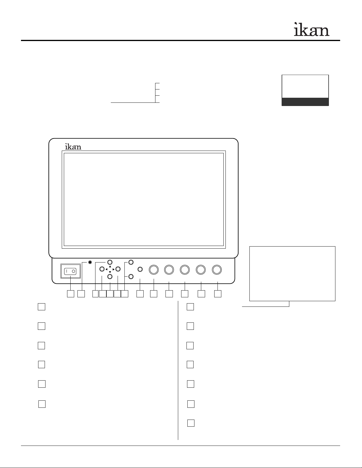
Front view
BP2-S Sony "L" Series
BP2-SU Sony "BP-U" Series
BP2-C Canon "900" Series
BP2-P Panasonic "D54" Series
VX7
Checked by
VIDEO
F1
YPbPr
SDI
Power Switch
1
ON OFF
1
HDMI
2 3 4 5 6
F2
7
Power ON / OFF
Power Indicator Light
2
When the power is ON, the LED green lights up.
VIDEO Selection Switch
3
Video input
4
SDI Selection Switch
Serial digital interface input (HD/SD compatible)
5
HDMI Selection Switch
High-Definition Multimedia Interface input
YPbPr Selection Switch
6
Analog component or RGB input
ASPECT/
MENU
EXIT
BRIGHT/
R
CONTRAST/
G
CHROMA/
B
8 9 10 11 12 13
F1 and F2 Buttons
7
Function key actions are selected in the menu.
ASPECT/EXIT Selection Button
8
Aspect: 16:9, 4:3, Full
In MENU, it is to exit the menu.
MENU Knob
9
It is to display menu, select settings, and adjustments.
(Push the knob to select, turn the knob to adjust settings.)
10
BRIGHT/R Knob
1: Adjust brightness 0 - 60 (30)
2: Adjust red channel
11
CONTRAST/G Knob
1: Adjust contrast 0 - 60 (30)
2: Adjust green channel
CHROMA/B Knob
12
1: Adjust chroma 0 - 60 (30)
2: Adjust blue channe
13
TINT/SHARPNESS Knob
1: Adjust tint 0 - 60 (30)
2: Adjust sharpness 0 - 60 (30)
TINT/
SHARPNESS
User programmable function buttons.
For quick access, the user may program
the F1 and F2 buttons to enable frequently
accessed monitor features. Via the main
monitor configuration menu, either button
may be assigned to perform the following
functions: Window 1, Window 2, HV
delay, Blue Gun, and Pixel to Pixel, .
3903 Stoney Brook Dr. Houston TX 77063. 1-713-272-8822. support@ikancorp.com © 2010 ikan Corporation. All right reserved. www.ikancorp.com
QUICK START GUIDE / VX7 LCD MONITOR
MONITOR DIAGRAMS
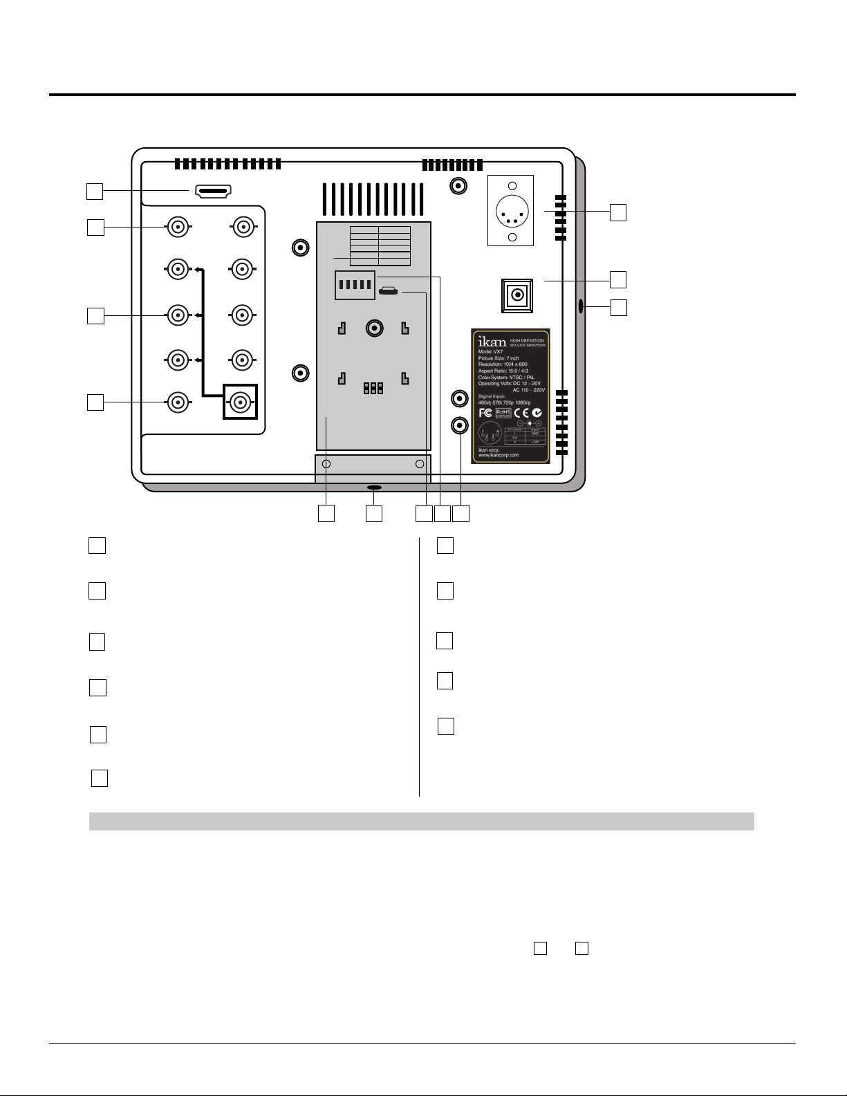
Rear view
1
2
3
4
OUT
OUT
HDMI
HDMI
VIDEO
VIDEO
Y/C
Y
Y
Pb
Pb
Pr
Pr
SDI
SDI
IN
On
Switch
50p
1
30p
2
720p
1080p
ON
Switch
1
1 2 3 4 5
2
720p
3
4
1080p
5
ON
OFF
1 2 3 4 5
CAUTION: TURN OFF POWER
BEFORE ADJUSTING
SWITCHES
CAUTION: TURN OFF POWER
IN
BEFORE ADJUSTING
+ +
3
4
5
OFF
On
50p
30p
25p
24p
24psf
SWITCHES
25p
24p
24psf
+ +
Illustration of the VX9 model
+
+
DC 12V - 20V
DC 12V
DC 12V - 20V
6
5
10
DC 12V
+
+
0
HDMI terminal
1
HDMI input only
11
1
9 8
7
Vesa 100mm Mount Holes
7
Threaded for
M4x.07 screws. Use to attach pro battery
plate adapter or for mounting third party vesa mounts.
VIDEO terminal (BNC)
2
IN : Composite signal input terminal
OUT: : Input signal through-out terminal
3
YPbPr terminal (BNC)
IN : Component signal input terminal
OUT: : Input signal through-out terminal
4
SDI (HD/SD) terminal (BNC)
IN : SDI input terminal - 1.5G
OUT: : Input signal through-out terminal (Reclock)
DC 12V power terminal
5
Standard DC Connection
DC 12V-20V power terminal
6
8
DIP Switch
Enable special 720p modes. For the monitor to correctly display
certain 720p signals, it is necessary to configure the DIP switches.
9
USB terminal
For factory service use only
10
¼-20 Threaded insert (on four sides of monitor)
Mounting Monitor
11
DV Battery Plate Slot
Mounting ikan DV battery plate
XLR DC Connection
**NOTE – The user must turn the monitor off before making changes to the DIP switches. Failure to do so may damage the monitor or make the monitor unusable.
DIGITAL TO ANALOG CONVERSION [SDI > YUV]
The monitor can convert digital SDI signals to Analog YUV. A signal from the SDI will be displayed on the YPbPr analog
outputs. This is a straight digital to analog conversion only. There is no up converting, down converting or standards
conversion available in this feature. This feature works in one direction SDI to analog. It will not work in reverse.
POWERING THE MONITOR
1. Plug the AC power adapter into the power input jack (See rear view diagram or above).
6 7
2. Attach the DV battery plate on the slot, and connect DV battery to the plate.
3. Connect a pro battery using the optional pro battery plate and then plugging that plate with the power tap cable into
the DC-In connector. The pro battery plate kits (PBK17-S or PBK17-A) allow you to go into the field using standard
V-Mount or Gold-Mount batteries.
3903 Stoney Brook Dr. Houston TX 77063. 1-713-272-8822. support@ikancorp.com © 2010 ikan Corporation. All right reserved. www.ikancorp.com
 Loading...