

Page 1
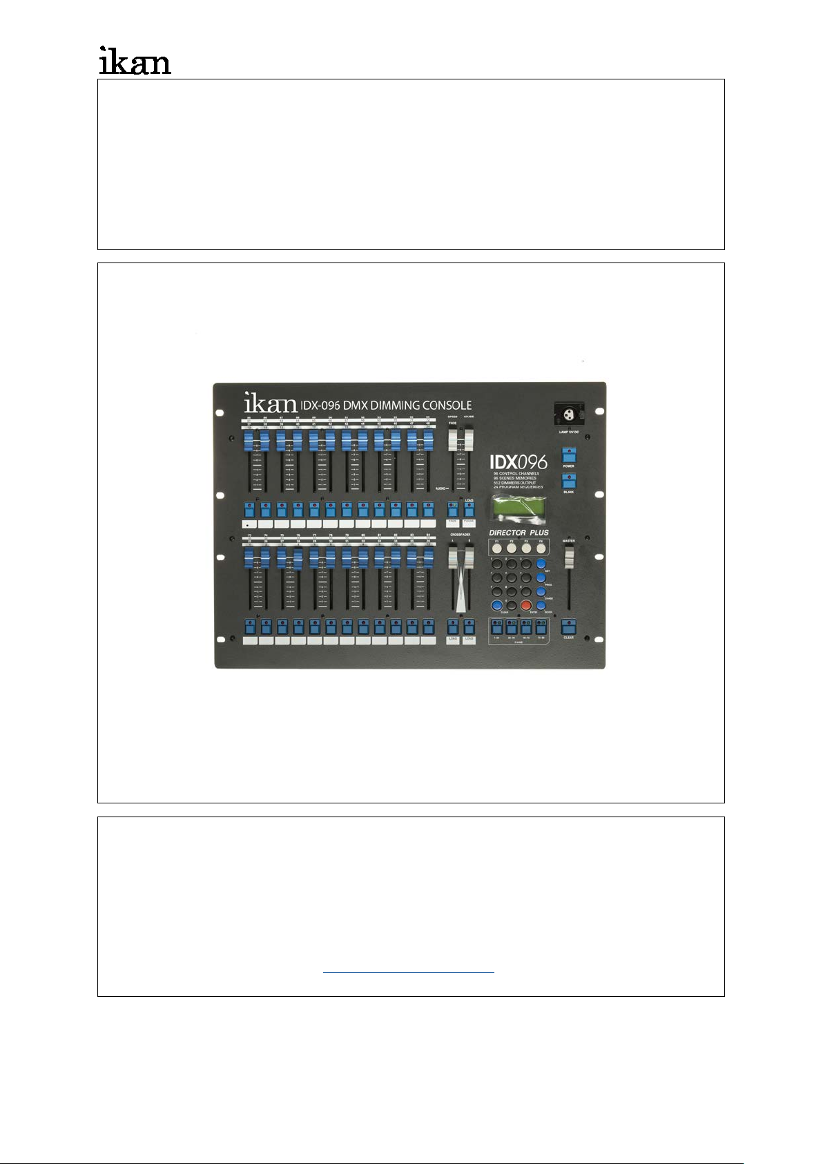
IDX-096
【
ikancorp.com
DMX 96 Control Channel Dimming Con troller
User Manual】
Ikan International Corporation
11500 S. Sam Houston Pkwy West, Houston, TX 77031
1.713.272.8822
For all general support
IDX-096
Page 2

ikancorp.com
1
Introduction
CHAPTER 1. FEATURES & FUNCTIONS
1-1 Features ................................................................................................................... 2
1-2 Specifications ......................................................................................................... 2
1-3 Dimensions ............................................................................................................. 3
CHAPTER 2. SPECIFICATIONS
2-1 Control panel features & functions ....................................................................... 4
2-2 Rear panel features & functions ............................................................................ 5
CHAPTER 3. POWER SWITCH .............................................................................. 6
CHAPTER 4. CHANNEL
4-1 Brightness value ..................................................................................................... 7
4-2 Brightness modification ......................................................................................... 8
4-3 Delete brightness setting ................................................................................... 8
CHAPTER 5. SCENE
5-1 SCENE setting ......................................................................................................... 9
5-2 SCENE 1… SCENE 96 loading ............................................................................. 10
CHAPTER 6. SEQUENCE
6-1 SEQUENCE Editing ............................................................................................... 12
6-2 SEQUENCE Modification ...................................................................................... 13
6-3 CHASE Loading .................................................................................................... 13
6-4 CHASE Fade On/Off Setting ................................................................................. 14
6-5 Stop CHASE execution ......................................................................................... 15
CHAPTER 7. A/B CROSS FADERS SWITCHING
7-1 Save SEQUENCE into A/B CROSS FADER ......................................................... 16
7-2 Load A/B CROSS FADER .................................................................................... 16
7-3 Pause A/B CROSS FADER ................................................................................... 16
CHAPTER 8. SET FUNCTION
8-1 LCD display / system default setting ................................................................. 17
8-2 Output memory card loading / saving ............................................................... 18
8-3 Channel patch setting / warm-up setting .......................................................... 19
8-4 Lock / Unlock setting ........................................................................................ 21
IDX-096
Page 3
ikancorp.com
2
Power supply
AC 90-240V, 45-63Hz
Digital control signal input / output
DMX512 / 1990
CH 97 – CH 512
Digital control connector
XLR 5-pin, XLR 3-pin, RJ11
max. value :AC 100mV
Gooseneck connector stand
XLR 3 -pin, DC +12V 250mA
Memory card
64k*2
482(w) x 352(h)x125(d)mm
Weight
5 Kg
Chapter 1. IDX-096 Features & Functions
1-1 Features
Digital signal output
96 control channels, and able to control up to CH97 – CH512 by patch
4 sets of PATCH editing functions
96 sets of scenes pre-set
( 24 sets of scenes able to save on every single page function )
24 sets of chase presets
Up to 64 scenes on each chase setting
2 sets of individual control sticks for scenes changes (CROSS FADE)
Audio controls available
Output external memory card saving / loading (options )
1-2 Specifications
Digital control channel 512channel by PATCH able to control
Audio input
Internal microphone MAX 120dB, output
Dimension 19” 8U standard rack
Warning!
1. Recharge the battery at least 24 hours on before start running. (Power
switch turned to ON, located on rear pa nel).
2. After first use, recharge th e battery within seven(7) days to avoid losing
saved data!
IDX-096
Page 4
ikancorp.com
3
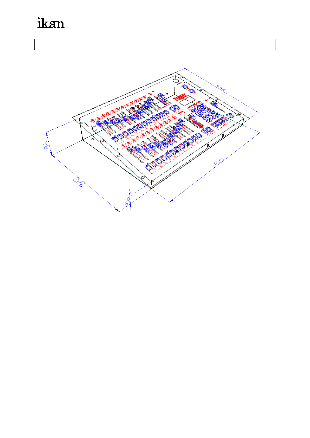
1-3 Dimensions
IDX-096
Page 5
ikancorp.com
4
11
12
1
2 8 3
9
10
16
18
CHAPTER 2. IDX-096 SPECIFICATION
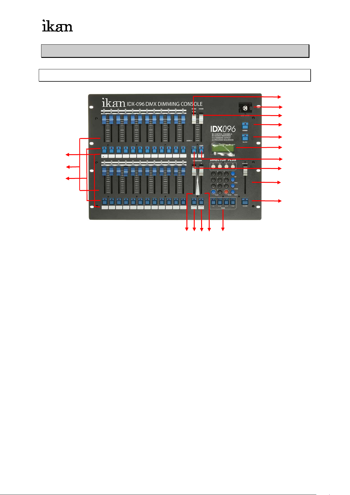
2-1 Introduction of control panel
(1.) VR1 ~ VR24 VR ....................... VR1 ~ VR24
(2.) P1 ~ P24 hot key ...................... P1 ~ P24
function 1 :The LED on function key display the channel status ( In channel
mode )
function 2:In SCENE mode, for SCENE selection
function 3:FLASH
function 4:LOAD + P1 - P24 hot key for chase function
(3.) Blank .....................................indication / memo for user
(4.) SPEED / FADE VR ...............Adjustment of chase speeding / CROSS FADE
speeding
(5.) FADE save key ....................CROSS FADE mode use
(6.) CHASER VR .........................chase brightness value adjustment
(7.) LOAD / PAUSE .....................Load / Pause:auto chase mode use
(8.) A-CROSSFADER VR ............Manual chase A execution mode
(9.) LOAD ....................................Load / Switch:Manual chase A mode use
(10.)B-CROSSFADER VR ........... Manual chase B execution mode use
(11.)LOAD ....................................Load / Switch:Manual chase B mode use
(12.)PAGE ....................................PAGE 1~PAGE 4
IDX-096
Page 6
ikancorp.com
5
29
CLR
7
1
4
F1
2728
ENTER0
8 9
SC/CH
CHASE
26
25
3 SET2
5 6 PROG
F2 F3 F4
24
23
2019
21 22
1 2 3
4
5
6
(13.)Gooseneck ............................ C+12V 250 Ma
(14.)POWER ................................power switch
(15.)BLANK ..................................Pause
(16.)LCD .......................................LCD display
(17.)MASTER VR .........................Master VR
(18.)CLEAR ................................output clear
(19.)F1 ..........................................function key
(20.)F2 ..........................................function key
(21.)F3 ..........................................function key
(22.)F4 ..........................................function key
(23.)SET .......................................function key
(24.)PROGRAM ...........................function key
(25.)CHASE .................................Chase execution
(26.)SC/CH ...................................scene/channel switch
(27.)ENTER ..................................enter key
(28.)0 ~ 9 ......................................0 ~ 9
(29.)CLR .......................................Clear
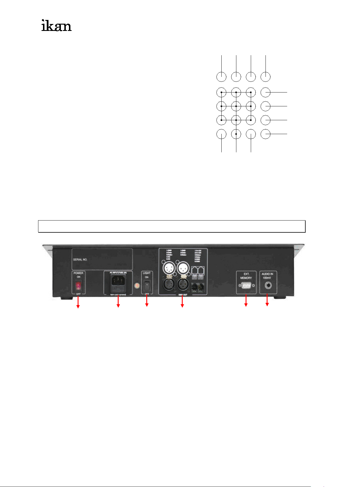
2-2 REAR PANEL
( 1) Power switch
( 2) Power In + Fuse
( 3) Goosenecks power switch
( 4) DMX 512 output
( 5) Memory card
( 6) Audio input
IDX-096
Page 7

ikancorp.com
6
CHAPTER 3 Switch
Switc h on
(1.) Plug into power source, and turn the power switch on rear panel
(2.) Turn the power switch on front panel, and check the LCD display status
(3.) Be sure that the LED on BLANK is off
Switch off
(1.) Turn off the power switch on front panel
★ Battery recharging mode
(2.) Turn off the power switch on rear panel
★ Battery un-recharge, 7 days duration of save data maintains only
Remark:User status will remain on afte r powered off
IDX-096
Page 8
ikancorp.com
7
PAGE START CH01
PAGE START CH25
PAGE START CH49
PAGE START CH73
Chapter 4. CHANNEL
4-1 Brightness value
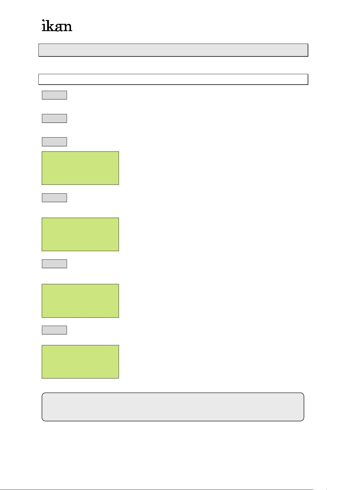
STEP-1 Adjust the【MASTER VR】to the top (MASTER VR adjust all control channel
brightness value)
STEP-2 press【SC/CH】key, to select the control channel mode (LED show green
light on page key)
STEP-3 press【PAGE 1】,adjust【VR 1 ~ VR 24】,to set CH. 01 ~ 24brightness value.
CHASE FADE ON
F1/2:FADE ON/OFF
STEP-4 press【PAGE 2】,adjust【VR 1 ~ VR 24】to 0 value, and adjust【VR 1 ~ VR
24】to set CH. 25 ~ 48 of brightness value.
CHASE FADE ON
F1/2:FADE ON/OFF
STEP-5 press【PAGE 3】,adjust【VR 1 ~ VR 24】to 0 value, and adjust 【VR 1 ~ VR
24】to set CH. 49 ~ 72 of brightness value.
CHASE FADE ON
F1/2:FADE ON/OFF
STEP-6 press【PAGE 4】,adjust【VR 1 ~ VR 24】to 0 value, and adjust【VR 1 ~ VR
24】to set CH. 73 ~ 96 of brightness value.
CHASE FADE ON
F1/2:FADE ON/OFF
P.S. When on page function, the VR should be adjusted to 0 value, and
move the VR key to get the new dimming value
IDX-096
Page 9
ikancorp.com
8
PAGE START CH01
4-2 Brightness Modification
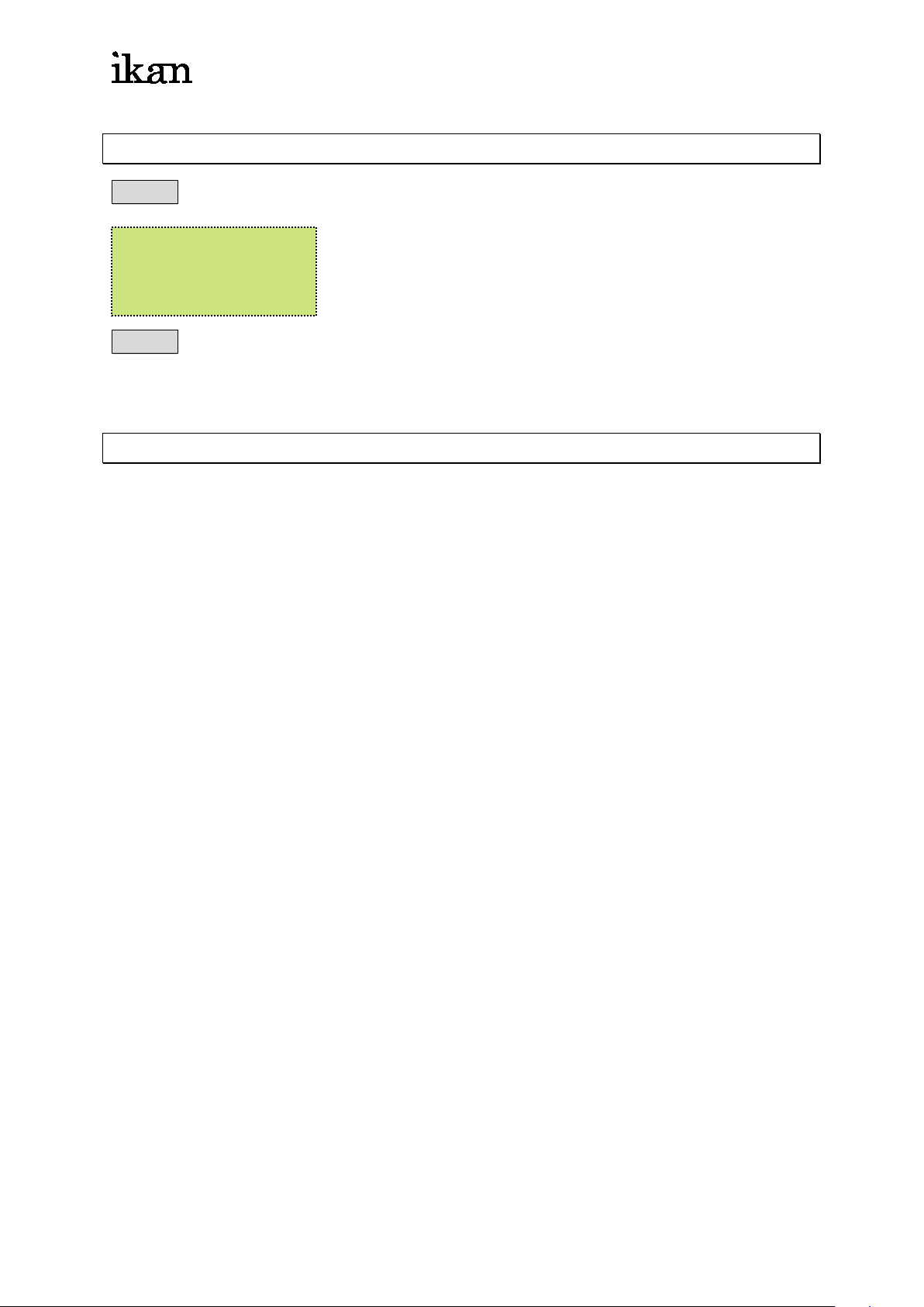
STEP-1 press【PAGE 1】(ch1-24)
CHASE FADE ON
F1/2:FADE ON/OFF
STEP-2 adjust【VR 1】key to CH01=00 value, and adjust VR key to top CH01=FL,
then adjust the【VR 1】key to CH01=50 to change the setting.
4-3 Setting Delete
adjust 【VR 1 ~ VR 24】and【MASTER VR】key to the bottoms “0”, and press the
CLEAR key on below of ”MASTER VR” key to delete.
IDX-096
Page 10
ikancorp.com
9
Chapter 5 SCENE
5-1 SCENE Setting
STEP-1 please refer to the chapter 4, adjust the dimming value on the control
channel.
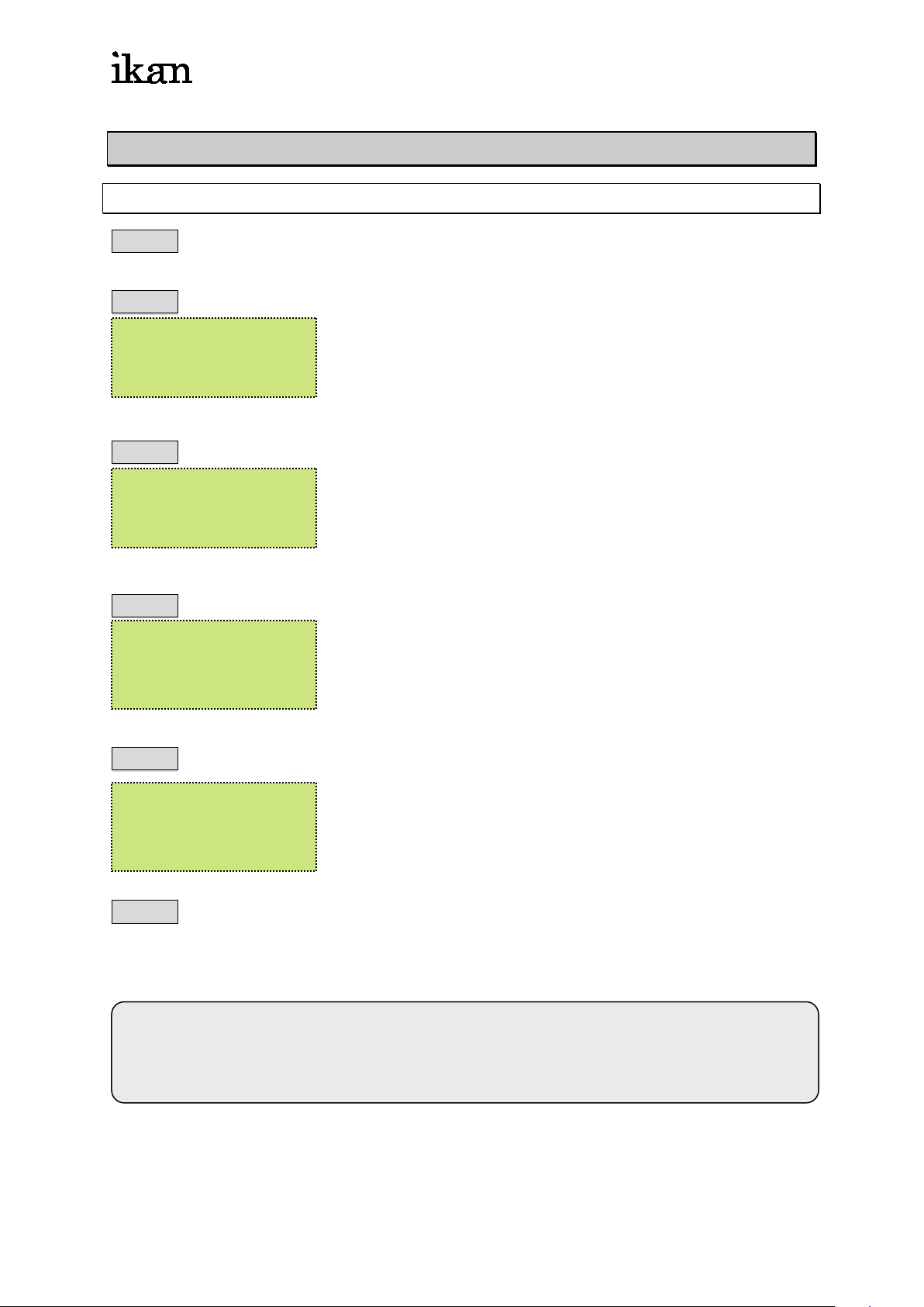
STEP-2 press【PROG】
F1: Scene
F2: Sequence
STEP-3 press【F1】,and select SCENE mode:
F1: Load F3: Clear
F2: Save
STEP-4 press【F2】,to save the SCENE
SELECT [01….. 96]
SAVE SCENE 01
STEP-5 press【ENTER】to confirm the selection
ARE YOU SURE ?F1
SAVE SCENE 01
STEP-6 for further SC2 --- SC96 setting, please refer to the setting procedure of above
Each【PAGE】 24 sets of SCENE setting available
PAGE 4 able to store 96 sets of scene
IDX-096
Page 11
ikancorp.com
10
【
【
5-2 SCENE 1 … SCENE loading
5-2-1 use【PROG】key for SCENE loading
STEP-1 Set all dimming value to 0% (refer to 4-3 )
STEP-2 Adjust【MASTER VR】key for dimming value
STEP-3 Press【PROG】, and press【F1】to select the SCENE mode
F1: Scene
F2: Sequence
STEP-4 Press【F1】key for SCENE loading
F1: Load F3: Clear
F2: Save
STEP-5 Press【0…9】key for number of SCENE loading
SELECT [01….. 96]
LOAD SCENE 01
STEP-6 Press【ENTER】to confirm the scene loading
5-2-2 Use【SC/CH】key for SCENE loading (FLASH status)
PAGE】LED ● → SCENE mode
PAGE】LED ● → CHANNEL mode
STEP-1 Set all dimming value to 0%. (refer to 4-3 )
STEP-2 Adjust the【MASTER VR】key
STEP-3 Press【PAGE 1】
STEP-4 Press【SC/CH】to select the SCENE mode.
IDX-096
Page 12
ikancorp.com
11
【1】
【2】
STEP-5 Press【P 1】for SCENE loading. (Flash status)
5-2-3 Adjust the【VR 1 ~ VR 24】key for SCENE loading
STEP-1 Adjust all control channel dimming value to 0% (refer to 4-3)
STEP-2 Adjust the【MASTER VR】
STEP-3 Press【PAGE 1】
STEP-4 press【SC/CH】to select SCENE mode (LED light on RED on PAGE key )
STEP-5 Adjust【VR 1】key to for SCENE loading
5-2-1 or 5-2-2: SCE NE speed loading
5-2-3:Adjust the VR key for dimming function
IDX-096
Page 13
ikancorp.com
12
press【F1】back to STEP-01
press【F4】to save
Chapter 6. SEQUENCE / CHASE
"SEQUENCE"
Definition: 2 sets of scenes or more for chase settings
Function:Provides the " CHASE " & " A/B CROSS FADER " control
procedures
Data memory: up to 24 SEQUENCE of memory data, and up to 64 steps
per SEQUENCE settings
6-1 SEQUENCE Editing
STEP-1 Press【PROG】key
F1: Scene
F2: Sequence
STEP-2 Press【F2】key to select Sequence mode
F1: Load F3: Edit
F2: Save F4: Clear
STEP-3 Press【F3】key for Sequence editing
F1 / 2/ 3/ 4=1/ + / - /E
SEQU.STEP01=S - -
press【F2】forward
press【F3】reward
STEP-4 Use【0…9】key to select the SCENE, and press 【ENTER】key to confirm
the selection
F1 / 2/ 3/ 4=1/ + / - /E
SEQU.STEP01=S - -
STEP-5 according to the STEP-3 procedures, to continues the SCENE setting, and
press【F4】key to complete the editing, and press【ENTER】to save
SELECT [01...24]
SAVE SEQUENCE01
IDX-096
Page 14
ikancorp.com
13
6-2 SEQUENCE Modification
STEP-1 Press【PROG】key
F1: Scene
F2: Sequence
STEP-2 and press【F2】key to select Sequence mode
F1: Load F3: Edit
F2: Save F4: Clear
STEP-3 press【F1】key, and press【0…9】key to select Sequence
SELECT [ 01..24 ]
LOADSEQUENCE01
STEP-4 Press【ENTER】key to confirm.
F1: Load F3: Edit
F2: Save F4: Clear
STEP-5 Press【F3】key for Sequence setting
6-3 CHASE Loading
6-3-1 CHASE loading
EX: Loading the first chase sequence
※ CHASE number = SEQUENCE number
STEP-1 press【CHASE】key
SELECT 01…24
CHASE: OFF 01
IDX-096
Page 15
ikancorp.com
14
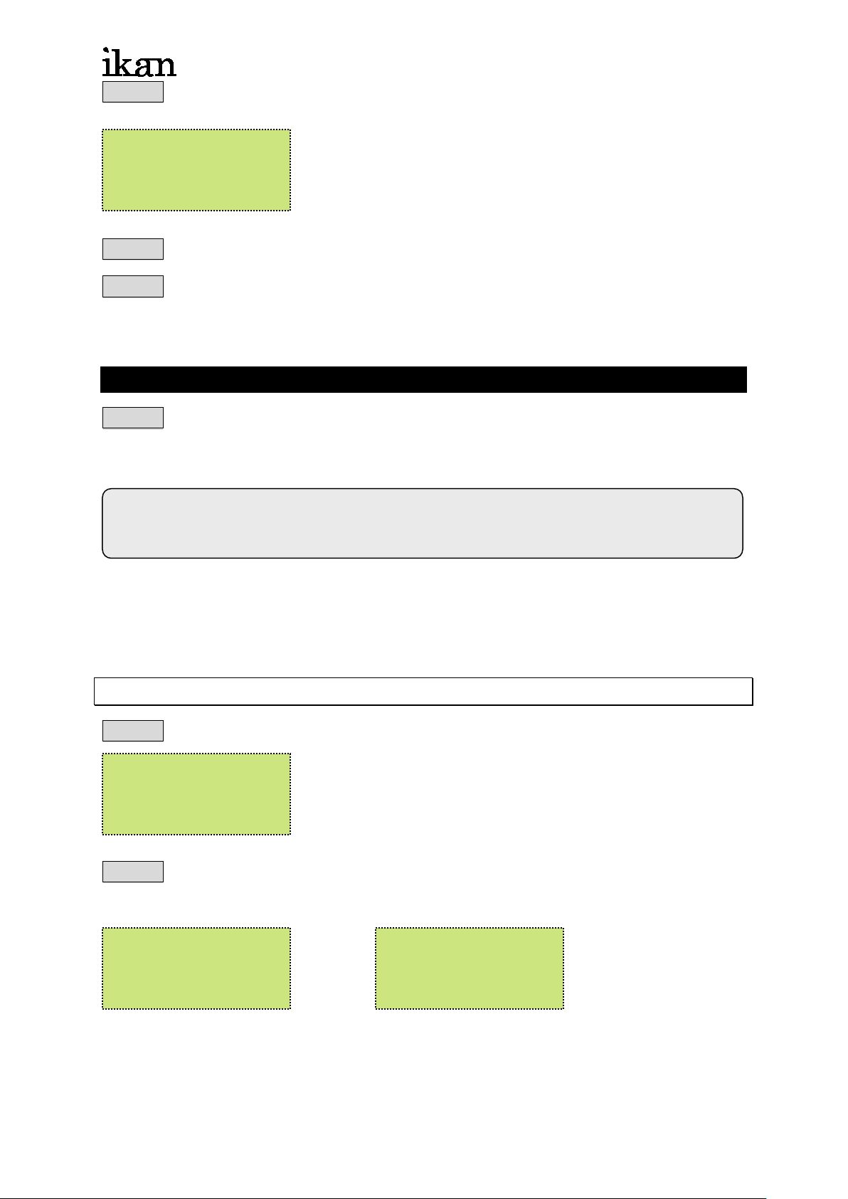
CHS=FL SPEED=FL
CHS=FL SPEED=FL
CHS=FL SPEED=FL
STEP-2 and press【0…9】to select the CHASE, and press【ENTER】to confirm the
selection
SELECT 01…24
CHASE: OFF 01
STEP-2 adjust the【CHASE FADER VR】to the top.(chase dimming value)
STEP-3 adjust【SPEED FADER VR】for chase speeding, for audio control, the VR
key should move to “0%“ value.
6-3-2 Use【P1-P24】for Chase Loading
STEP-1 press 【LOAD/PAUSE key on below of CHASER FADER VR】+【P 1】keys
together, for 1st set of chase loading, and press【P2】key for the following chase
loading
Press 【LOAD/PAUSE key below CHASER FADER VR】again to pause the
chase function, and press the same keys again to continue
Refer to 6-1 & 6-2 of setting procedures, for further chase setting, up to 24 sets of
chase settings available. And refer to 6-1 for chase loading
6-4 CHASE Fade On/Off Settings
STEP-1 adjust the【CHASER FADER VR】or【SPEED FADER VR】
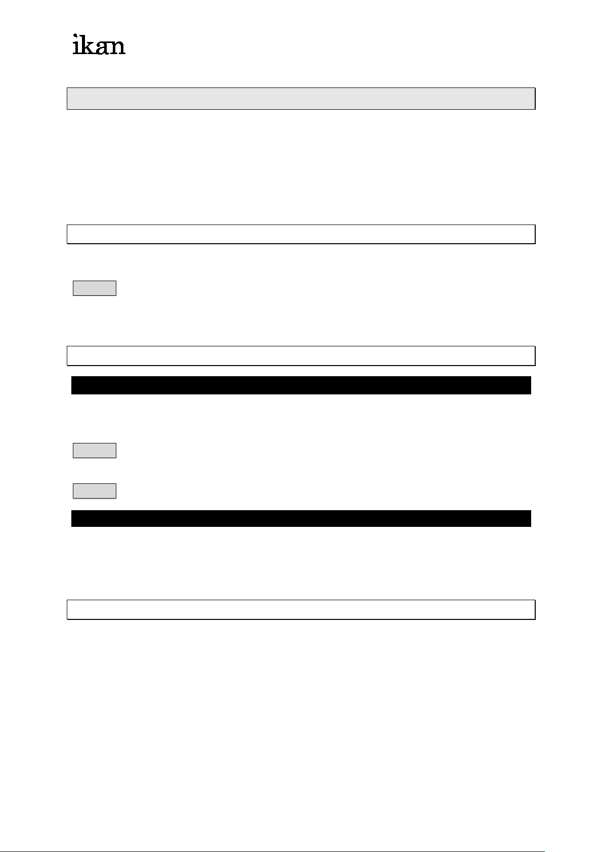
OFF Step=01
CHASE FADE ON
F1/2:FADE ON/OFF
STEP-2 press【F1】key, to enter CHASE FADE ON MODE.
press【F2】key, to enter CHASE FADE OFF MODE.
OFF Step=01
CHASE FADE ON
F1/2:FADE ON/OFF
IDX-096
OFF Step=01
CHASE FADE OFF
F1/2:FADE ON/OFF
Page 16

ikancorp.com
15
6-5 To stop the CHASE execution
Function 1.
Press twice【CHASE】key to stop
Function 2.
Adjust the【CHASE FADER VR】key to the “0%“ value to stop
IDX-096
Page 17
ikancorp.com
16
Chapter 7 A/B CROSS FADERS Scene switching
"A/B CROSS FADER"
2 sets of individual scene control VRs
In SEQUENCE mode, use A/B CROSSFADER to execute the manual chase
function.
7-1 To save the SEQUENCE to A / B CROSS FADER
EX:To load the Sequence to A CROSS FADER
STEP-1 Press【LOAD key below A CROSS FADER 】+【P 1】keys together to save
the current sequence into A CROSS FADER.
7-2 To load A / B CROSS FADER data
Function 1: Press the Load key below A/B CROSS FADER
The Fader time of A/B CROSS FADER control by SPEED VR key, according to 7-1,
to load the saving data from the SEQUENCE by the A CROSS FADER.
STEP-1 Adjust【SPEED / FADE VR】key, and press【FADE】to confirm the speed
setting, adjust the speed VR key, and press FADE key for modification
STEP-2 Press【A CROSS FADER VR】to the top, and press【LOAD】key for loading
Function 2: use A/B CROSS FADE R V R
According to the setting procedures of above, use the【A CROSS FADER VR】key
for further setting
7-3 To pause the A / B CROSS FADER
Adjust the 【A CROSS FADER VR】key to the “0%” value, and press【LOAD】key
to pause / stop
IDX-096
Page 18
ikancorp.com
17
Chapter 8 Other function setting
8-1 LCD display / default setting
8-1-1 Power switch for LCD background lighting
STEP-1 Press【SET】
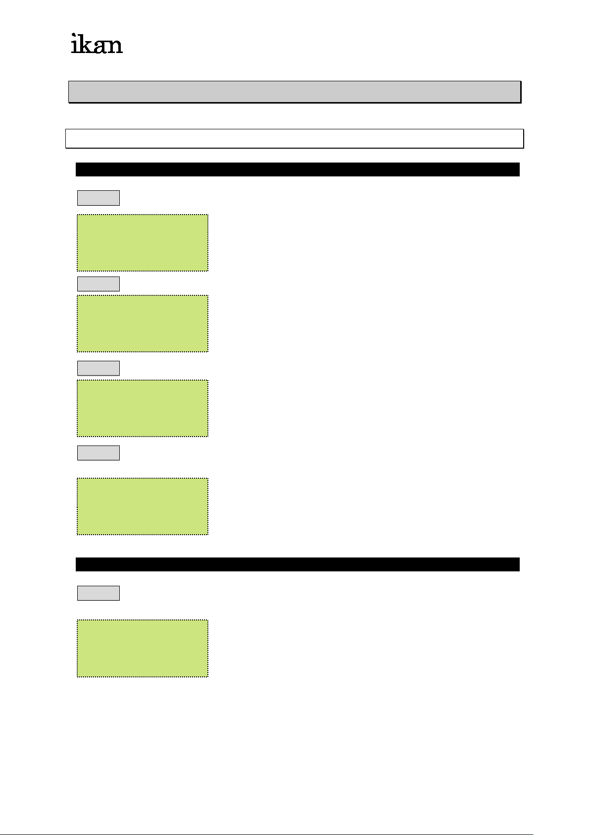
F1 : Setup F3 : Patch
F2 : Xio F4 : Lock
STEP-2 and press【F1】
F1 : Lcd
F2 : Reset system
STEP-3 and press【F1】
F1 : Backlight
F2 : Concen
STEP-4 and press【F1】for brightness of LCD background lighting, press【F1】again
to save.
F1 : Backlight
F2 : Concen
8-1-2 LCD contrast adjustment
STEP-4 refer to STEP-4, press【F2】key to adjust the contrast of LCD, and press
【F2】again to confirm.
F1 : Backlight
F2 : Concen
IDX-096
Page 19
ikancorp.com
18
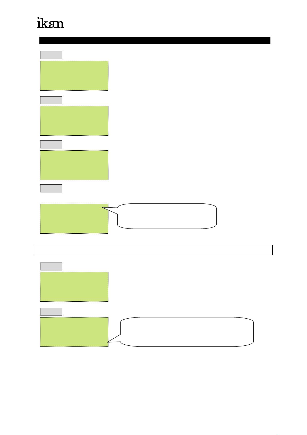
* DESK BLACK OUT *
BY LITE PUTER
8-1-3 DATA delet e
STEP-1 press【SET】
F1 : Setup F3 : Patch
F2 : Xio F4 : Lock
STEP-2 and press【F1】
F1 : Lcd
F2 : Reset system
STEP-3 and press【F2】
Reset All Data!
Are You Sure? F1
STEP-4 and press【F1】to delete all data, the BLANK will activate, press【BLANK】
key to continue the further setting.
CX-12
V2.08 ( C ) 1997- 98
The display will be blinking
8-2 External memory card save / load
STEP-1 Press【SET】
F1 : Setup F3 : Patch
F2 : Xio F4 : Lock
STEP-2 and press【F2】
F1 : Read
F2 : Save
press【F1】for external memory loading
press【F2】for external memory saving
IDX-096
Page 20
ikancorp.com
19
press【F1】to DIMMER 001
press【F4】DIM address selection
press【F1】DIMMER097
8-3 Channel patch sett ing / war m up se t t ing
8-3-1 Channel patch setting ( up to 4 sets of settings )
EX: To patch DIMMER 097 channel to CH01 of CX-12
STEP-1 Press【SET】
F1 : Setup F3 : Patch
F2 : Xio F4 : Lock
STEP-2 and press【F3】
F2:DMXo F4:Wrmup
F3:DMXin
STEP-3 and press【F2】
F1 : Load F3 : Edit
F2 : Save F4 : Clear
STEP-4 and press【F3】
F1/ 2 / 3 / 4=1/ + / - /d
DIMMER001<=CH01
press【F2】DIM to + 1
press【F3】DIM to -1
STEP-5 Press【F4】,for DIM staring address
1:97 2:193 3:289
DIMMER001<=
press【F2】DIMMER193
press【F3】DIMMER289
STEP-6 Press【F1】for DIMMER097<=CH--
F1/ 2 / 3 / 4=1/ + / - /d
DIMMER097<=CH--
STEP-7 key【0】,【1】for DIMMER097<=CH01, and press【ENTER】key to confirm
IDX-096
Page 21
ikancorp.com
20
DIMMER097<=CH01
the setting, the DIMMER097 had PATCH to CX-12 CH01
F1/2/3/4=1/+/-/d
STEP-8 press【SET】to escape
F1 : Load F3 : Edit
F2 : Save F4 : Clear
STEP-9 press【F2】to save (4 sets of settings available F1~F4 )
STEP-10 press【F1】to load the patch data from F1~F4
STEP-11 press【F4】to delete the data, and back to the default setting
8-3-2 Warm-up setting 0~9%
STEP-1 press【SET】
F1 : Setup F3 : Patch
F2 : Xio F4 : Lock
STEP-2 and press【F3】
F2:DMXo F4:Wrmup
F3:DMXin
STEP-3 and press【F4】
F1 : ALLCh
F2 : LoadSc F4 :Clr
1.【F1】: to select all channel warm-up setting
2.【F2】: SCENES loading
3.【F4】: to delete the last step scene setting
IDX-096
Page 22
ikancorp.com
21
【F1】
【F2】
8-4 Lock / Unlock function
8-4-1 password setting
STEP-1 press【SET】
F1 : Setup F3 : Patch
F2 : Xio F4 : Lock
STEP-2 and press【F4】
F1 : Pgm.
F2 : Key
:SET, PROG key lock
:all function key lock
STEP-3 press【F1】,to lock【PROG】key
LOCK PROGRAM:
PASSWORD : 0000
Enter 4-digit number, or enter “6248” (default
password setting)
STEP-4 press【ENTER】key to confirm the setting
8-4-2 Unlock
press【SET】, and press 4-digit password【XXXX】and press【ENTER】to unlock
IDX-096
 Loading...