

Page 1
20000017582
IKA Vacstar digital_112017
IKA Vacstar digital
Operating instructions EN 5
Source language: German
Mode d’emploi FR 19
Instrucciones de manejo ES 33
Instruções de serviço PT 47
Page 2
Device setup
A
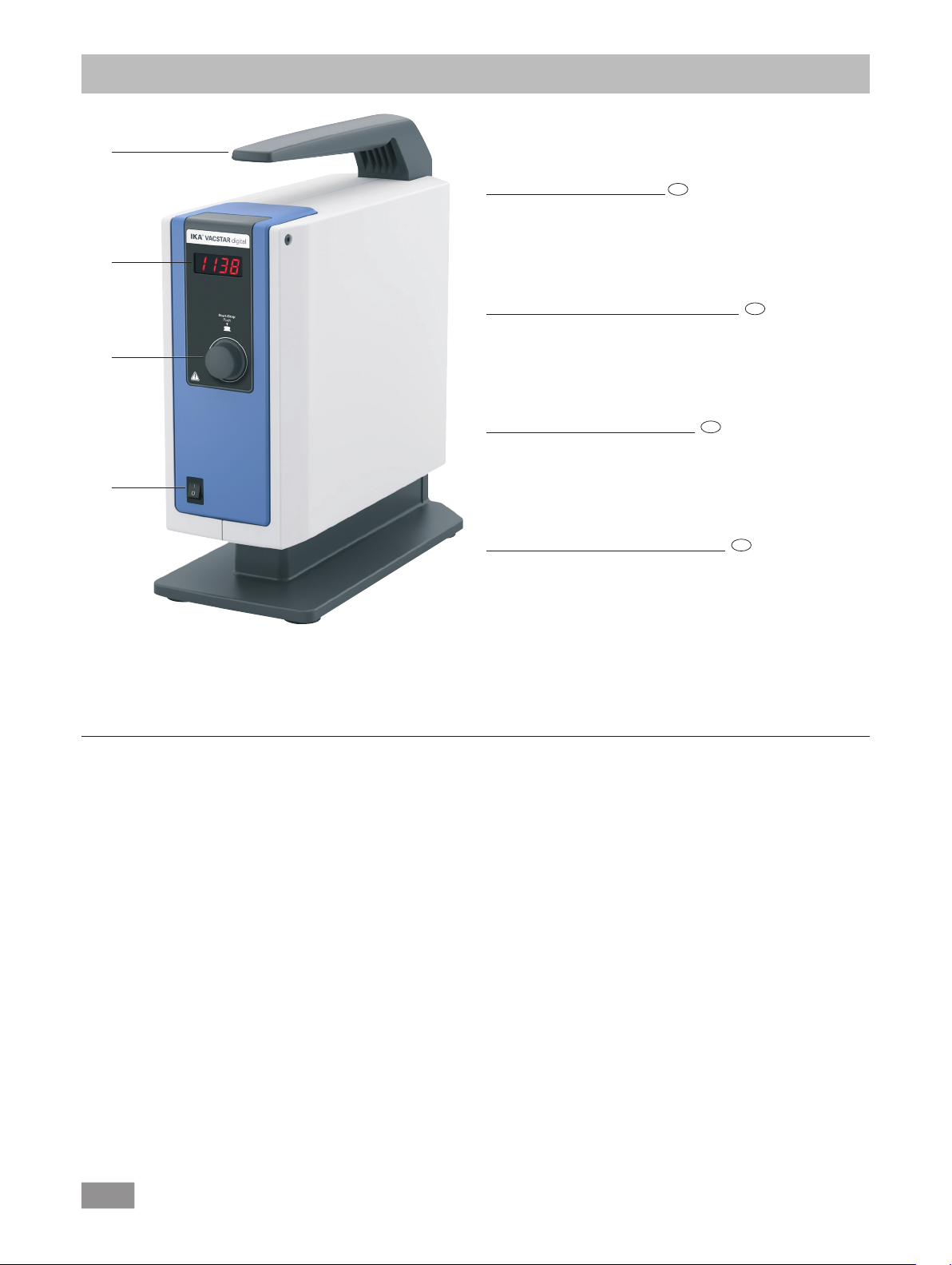
Pos. Description
EN
A Handle
B Display
C Rotating/pressing knob
B
D Main switch (on/off)
Pos. Désignation
FR
A Poignée
B Achage
C
C Bouton rotatif/poussoir
D Interrupteur principal (marche/arrêt)
Pos. Denominación
ES
A Asa
B Pantalla
D
C Mando giratorio/pulsador
D Interruptor principal (on/off)
Item Designação
PT
A Alça
B Tela
C Botão giratório/de pressão
D Interruptor principal (liga/desliga)
Fig. 1
2
Page 3
E
F
G
H
I
J
K
L
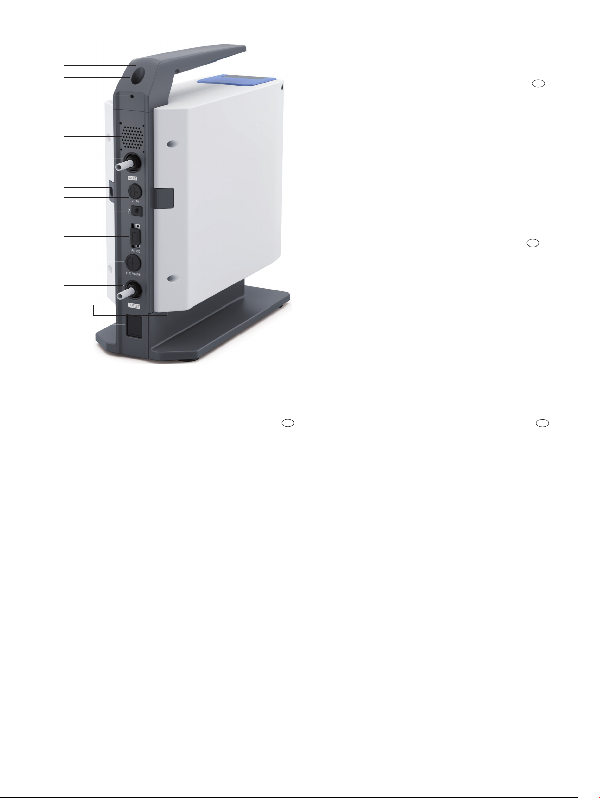
Pos. Description
E Handle securing screw
F Vacuum controller VC 10 stand hole
G Stand securing screw
H Fan / ventilation slit
I Hose connection for suction line d= 8 mm (INLET)
J Accessory fastening (emission condenser)
K Connection for vacuum controller VC 10 (Mini DIN)
L USB interface
M RS 232 interface
N Water valve connection
O Hose connection for pressure line d= 8 mm (OUTLET)
P Power supply cable connection
EN
M
N
O
H
P
Fig. 1
Pos. Denominación
E Tornillo de fijación del mango
F Orificio de soporte del controlador de vacío VC 10
G Tornillo de fijación del soporte
H Ventilador/Ranura de ventilación
I Conexión de manguera para el conducto de aspiración
d= 8 mm (INLET)
J Fijación de accesorios (condensador de emisiones)
K
Conexión para el controlador de vacío VC 10 (mini DIN)
L Interfaz USB
M Interfaz RS-232
N Conexión para la válvula de agua
O Conexión de manguera para el conducto de presión
d=8mm (OUTLET)
P Conexión para el cable de alimentación
Pos. Désignation
E Vis de sécurité de la poignée
F Alésage de statif contrôleur de vide VC 10
G Vis de sécurité du statif
H Ventilateur/Fente de ventilation
I Raccord de flexible de la conduite d’aspiration
d= 8 mm (INLET)
J Fixation d’accessoire (condenseur d’émissions)
K Prise contrôleur de vide VC 10 (mini DIN)
L Port USB
M Port RS 232
N Prise vanne d’eau
O Raccord de flexible de la conduite de refoulement
d= 8 mm (OUTLET)
P Prise pour le câble réseau
ES
Item Designação
E Parafuso de trava da alça
F Controlador de vácuo VC 10 furo do suporte
G Parafuso de trava do suporte
H Ventilador/furos de ventilação
I Conexão para linha de sucção d= 8 mm (INLET)
J Fixação acessórios (condensador de emissão)
K Conexão para controlador de vácuo VC 10 (Mini DIN)
L Interface USB
M Interface RS 232
N Conexão para válvula de água
O Conexão para linha de descarga d= 8 mm (OUTLET)
P Conexão para cabo de rede
FR
PT
Page 4

Page 5
Source language: German
Contents
Device setup .............................................................................................................................................................................. 2/3
Declaration of conformity .......................................................................................................................................................... 5
Warning symbols ....................................................................................................................................................................... 5
Warranty ................................................................................................................................................................................... 5
Safety instructions ...................................................................................................................................................................... 6
Unpacking ................................................................................................................................................................................. 7
Correct use ................................................................................................................................................................................ 8
Useful information ..................................................................................................................................................................... 8
Setting up .................................................................................................................................................................................. 9
Commissioning .......................................................................................................................................................................... 12
Interfaces and outputs ............................................................................................................................................................... 13
Maintenance and cleaning ......................................................................................................................................................... 14
Error codes ................................................................................................................................................................................ 15
Accessories ................................................................................................................................................................................ 15
Product contact parts ................................................................................................................................................................. 15
Technical data ............................................................................................................................................................................ 16
EN
Page
Declaration of conformity
We declare under our sole responsibility that the product to which this declaration relates is in conformity with directives 2014/35/EU,
2006/42/EC, 2014/30/EU an
EN 61326-
1 and EN ISO 12100.
d 2011/65/EU and conforms with the following standards or normative documents:
EN 61010-1, EN
60529
Warning symbols
DANGER
WARNING
CAUTION
NOTE
Indicates an (extremely) hazardous situation, which, if not avoided, will result in death, serious injury.
Indicates a potentially hazardous situation, which, if not avoided, can result in death, serious injury.
Indicates a potentially hazardous situation, which, if not avoided, can result in injury.
Indicates practices which, if not avoided, can result in equipment damage.
Warranty
,
According to IKA‘s Terms and Conditions of sale and delivery, this
product is covered by a warranty for a period of 24 months. Please
contact your dealer for any warranty claims. If you wish, you can
send the device directly to our
invoice and state the reasons for your guarantee claim. In this
case, you are responsible for shipping and handling costs.
factory
. Please
provide
the sales
The warranty does not cover wearing parts, nor defects that are
the result of improper use, insucient care and maintenance or
failure to follow the instructions in this operating manual.
5
Page 6
Safety instructions
For your protection
NOTE
• Keep the instruction
accessed easily.
• Ensure that only trained staff use the device.
• Be sure to comply with all safety instructions, directives and
all matters of health, safety and accident prevention in the
workplace.
• The device and all parts of the device must not be used on
people or animals.
Device configuration
DANGER
• Set up the device in accordance with the chapter “Setting up”
and connect the connection lines and interfaces as described.
• Set up the device on a stable, even, non-flammable surface.
Accessories
• Safe
• Carefully observe the operating instructions for additional
• The pressure at the gas inlet and outlet must not exceed
operation
accessories as described in the “Accessories” section.
devices (e.g. rotary evaporators, vacuum controllers), with
which the vacuum pump IKA Vacstar digital is operated.
1100 mbar.
Please read the instruction manual
in full before use and follow the
safety instructions.
manual in a place where
The
vacuum
digital is not designed to be set up
in
potentially explosive atmospheres.
can only be
pump IKA Vacstar
ensured
when
working
it
can be
with
DANGER
• Do not expose human or animal body parts to vacuum.
• Do not work with the device underwater or underground.
• Never work with a faulty or incorrectly connected device.
• Set up the vacuum pumps in appropriate and
extractor hoods, or set up an exhaust gas line to them. Ensure
that the exhaust gas line cannot be kinked! The maximum
permitted exhaust gas line length is 2 metres.
• Occurence of explosive mixtures; if appropriate
gas for ventilation and/or thinning.
• Elastic elements may be pressed together under vacuum.
• Only use flexible hose lines.
• Observe your
ensure that the device is put in a safe state (see the chapter:
Commissioning, Operating mode).
Always wear personal protective
equipment in accordance with the
hazard class of the media being
worked with - otherwise there are
dangers due to spraying liquids,
and release of toxic or flammable
gases.
emergency
measures for power failure and
functioning
connect
inert
Work with the device
DANGER
WARNING
• The vacuum pump IKA Vacstar digital must only be operated
under the conditions described in the chapter “Technical data”.
• Prevent release of the materials listed above. Take measures
to protect staff and the environment.
• Pay attention to possible interactions or chemical or physical
You can prevent the release of solvent vapours into the atmosphere
using a downstream emission condenser.
The vacuum pump is not suitable
for use with
materials that
an air
Do not operate the pump while it is
open. Otherwise there is a danger
of severe injuries as a hand may be
pulled into the moving parts.
Inhaling or coming into contact
with media
liquids, gases, spray
dusts or biological materials can
endanger the health of the user.
Ensure that all connections are
well sealed and free of leaks if you
are working with such media.
self-igniting materials
are
flammable without
supply
, or
explosive
such as
materials.
poisonous
mists,
vapours,
reactions when working with media at reduced pressure and
increased temperature.
• There can be electrostatic processes between the medium
and the device which can lead to direct danger.
• Some medium may be released due to the residual leakage
,
rate of the device.
• Before commissioning check that all the housing parts are
present and fastened to the device.
• Do not lift the pump if the handle is loose and the handle
securing screw (E) is loose or missing!
• Only switch the pump on if the pump is standing vertically.
• Connect the hose connections (INLET-OUTLET) and interfaces
in accordance with
operating instructions.
• Ensure
• Ensure that vapours containing solvent can be sucked into
• Do not use the pump to create pressure.
• Observe the permitted pressure at the inlet and outlet side;
• The
• Use a solenoid valve or a check valve in the suction line if
• When using an emission condenser ensure that the coolant
that the
its ignition
increases the temperature of the medium additionally.
the pump.
see the chapter “Technical data”.
suction-side line.
there are several load units.
is flowing freely.
temperature.
gas
flow must only be regulated/throttled in the
the
temperature
The pumping process
labelling on
of the evacuated
the device and the
medium is below
(compression)
6
Page 7
Protection of the device
WARNING
CAUTION
• The device is only disconnected from the power supply when
the power or device plug is removed.
• The socket for the power supply cable must be easy to access.
• Covers or parts that can be removed from the device without
tools must later be refitted to ensure safe operation, unless
anything else is connected at this point. This will prevent the
infiltration of foreign objects, liquids and other contaminants.
• Unwanted liquids
extracting air during no-load operation.
• Avoid knocks or impact to the device.
Ensure that the substances used
with the device are compatible
with the materials of the device
parts that come into contact with
the
product; see
“
Product
The
rating plate must coincide with the
actual power supply.
that
contact parts”.
specified settings on the
have entered
the
chapter
can be removed by
Unpacking
Unpacking
• Unpack the device carefully.
• Any damage should be notified immediately to the shipping
agent (post oce, railway network or transport company).
• The device must only be opened by trained, skilled personnel
(who have been authorised to do so).
• The device must not be modified without authorisation from
IKA.
• To ensure sufficient cooling for
digital, the ventilation slits on the housing must not
Vacstar
be covered.
• Only use original
ensure that the device works reliably.
• Watch out for
device. Warm up the device first, if it has been brought in
from a cold environment.
• Never fasten the vaccum pump over a heating bath.
• Ensure that no solids and/or liquids can enter the diaphragm
of the vacuum pump IKA Vacstar digital through the suction
line of the pump. This damages the diaphragm and other
internal parts of the pump. This reduces delivery capacity and
the final pressure can no longer be achieved. Deposits may
be produced in the interior, reducing service life and causing
leaks.
replacement
water condensation
the vacuum pump IKA
parts for
maintenance
inside and outside the
to
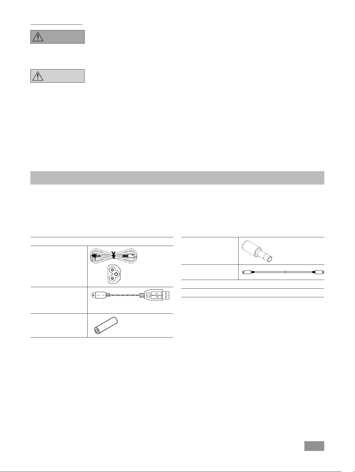
Scope of delivery
Diaphragm vacuum pump
Power supply cable
Laptop Euro
Power supply cable
Laptop GB
Power supply cable
Laptop CH
USB A - USB B cable
Vacuum hose 1m
IKA Vacstar digital
Silencer
Connecting cable MVP
10.100
Operating instructions
A
Warranty card
7
Page 8
Correct use
Use
WARNING
The laboratory diaphragm vacuum pump
together with other laboratory devices to create a vacuum.
For specific vacuum control, an additional vacuum controller IKA
VC 10 or IKA rotary evaporator RV 10 auto is required.
Area of use (only indoors)
The device is suitable for use in
The safety of the user cannot be ensured:
• if the device is used in conjunctions with accessories not
made or recommended by the manufacturer!
The device must not be used for:
- evacuating biological habitats,
-
evacuating explosive, corrosive
or similar gases,
- throughput/use of liquids
The device is not suitable for:
- pumping up objects
- pumping liquids
- use in potentially explosive
atmospheres
- underwater
- underground
residential
IKA Vacstar digital is
areas and all other areas.
used
Standalone operation
The vacuum pump can be operated without a controller.
The delivery
speaking, the smaller the volume to be evacuated, the lower the
speed should be. The final pressure is not controlled.
Operation with accessories
Along with the accessories recommended by IKA, the vacuum
pump
specified final pressure e.g. for operating an IKA
It can also be used for classical separation, filtration or drying in
the laboratory.
With an appropriate vacuum controller
evaporator (e.g. RV 10 auto), the
automatically, for automatic boiling point detection, scheduled
pressure-time
Intended use: Tabletop device
• if modifications are made to the device or parts of the device
• if the device is
capacity
IKA Vacstar digital
by third parties!
instructions!
can be set using the adjustable speed.
is suitable for controlled evacuation to a
(e.g. VC 10)
Vacstar digital
curves or programs from the solvent library, for example.
operated in contravention of the safety
rotary evaporator.
can be operated
Generally
or with a rotary
DANGER
CAUTION
Useful information
You can
solvent vapours into
using
condenser.
Special care must be taken when
working with gas
include condensable gases (e.g.
solvents). If diaphragm pumps are
used with
in the pump’s air flow. This leads
to a build-up of pressure in the
vacuum chamber,
influences the effectiveness and
service life of the diaphragms and
valves.
If liquid or condensate enters the
vacuum chambers, the specified
minimum working pressure is no
longer achieved.
To
diaphragms against liquid, use an
upstream condensate separator,
such as a Woulff bottle.
prevent the release
the atmosphere
a downstream emission
mixtures
such
gases they
which in turn
protect
the inner valves and
of
that
condense
CAUTION
NOTE
Diaphragm vacuum pumps are oscillating displacement pumps.
The diaphragms expand the volume of the vacuum chamber to
produce an underpressure, which sucks air into the chamber. The
air is then pressed out of the vacuum chamber by subsequent
compression. Changes between the inlet and outlet are controlled
by diaphragm valves.
The physical unit for pressure is 1 Pascal [Pa].
However people often still use the unit millibar [mbar] colloquially.
1 mbar = 100 Pa
1 bar = 10
1 Pa = 10
1 Pa = 0.01 mbar
5
Pa
-5
bar
It is generally recommended that
you run the pump with no load at
the end of the
operation, approx. 3 up to max. 5
minutes) to dispel any residues in
the pump.
If applicable, vent the recipient.
To do this, remove the suction line
during manual operation.
Observe the operating instructions
of the relevant devices.
process (no-load
8
Page 9
A distinction
is made
between different ranges
in vacuum
technology.
Rough vacuum: 10
Fine vacuum: 10² to 10
High vacuum: 10
Ultra high vacuum < 10
5
to 10² Pa (1000 to 1 mbar)
-1
-1
Pa (1 to 10-3 mbar)
to 10-5 Pa (10-3 to 10
-5
Pa (< 10
-7
mbar)
-7
mbar)
The periodic movements of the diaphragms create a vacuum at
the pump inlet. Diaphragm vacuum pumps work with a rough
vacuum of up to 10
2
Pa. Lower pressures cannot be achieved with
these pumps.
To create fine, high and ultra high vacuums, oil-sealed vacuum
pumps, screw pumps, diffusion pumps or turbomolecular pumps
must be used, for example. Diaphragm vacuum pumps are often
used as pumps for the preliminary stage in these contexts.
Compressing and releasing the pressure on air creates a noise. The
pump is quieter the less air is transported. This means that there
is less operating noise during normal operation if the pressure is
reduced.
A fitted exhaust hose with a sound absorber can also be used to
reduce noise.
In automatic operation with controlled speed the pump reduces
its speed when it reaches the target value. If the leakage rate in the
entire system is low enough, the speed may even be set to “zero”.
When combined with the vacuum controller VC 10 or the
rotary
evaporator with integrated vacuum controller RV 10 auto,
the
pump can
also
be used for
“two-position control” (valve-controlled)
or “analogue speed control” of the vacuum.
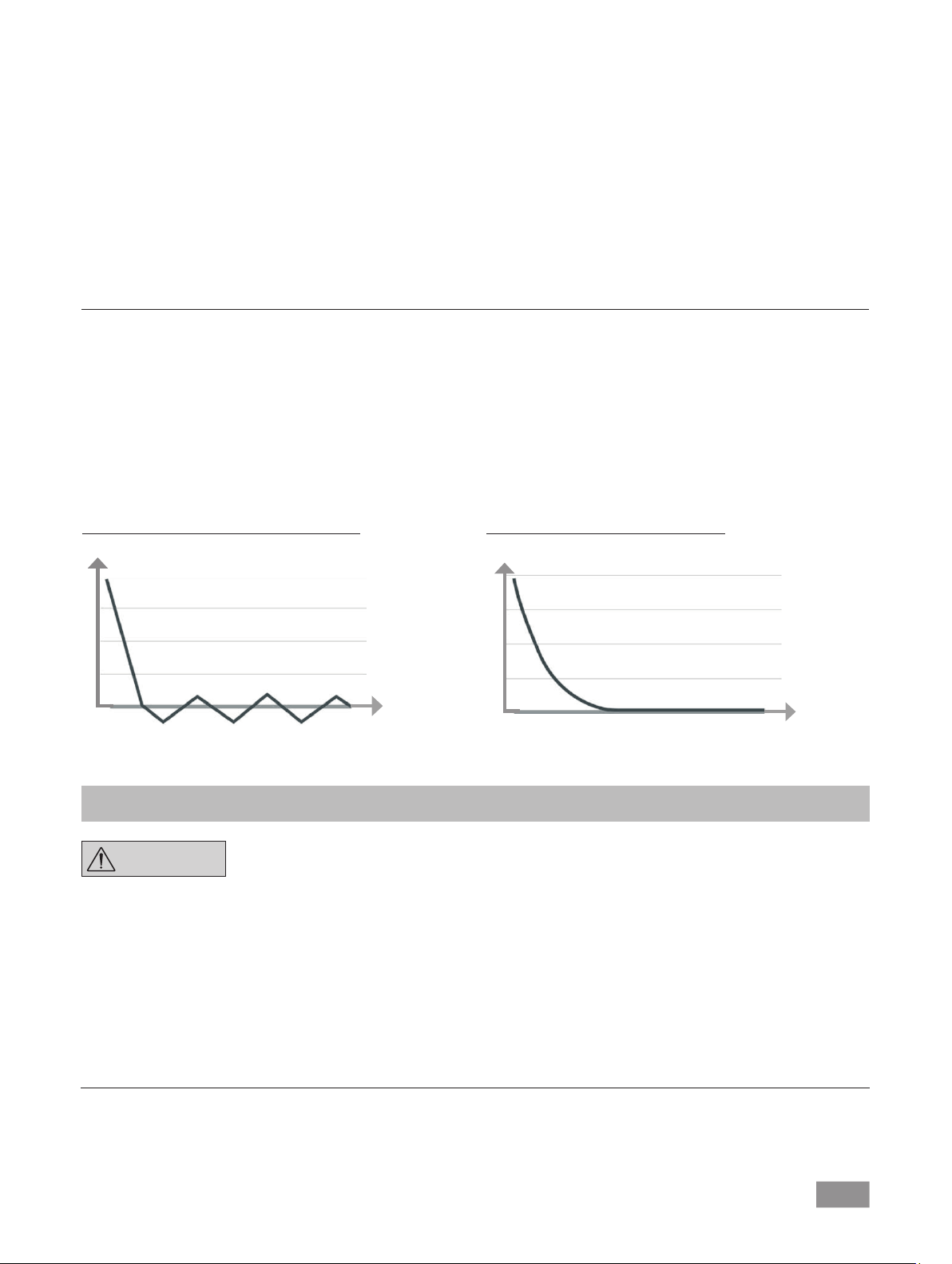
Two-position control
When the target value is reached, the suction line is interrupted.
Due to the small delay between the times when the pressure value
is detected, when comparison is made with the target value, when
a vacuum valve is switched off and when the suction line of the
vacuum-producing system are switched off, it is easy to go below
the set target value. If the pressure in the system goes up again
due to a natural leakage rate, the suction line valve opens.
Schematic view of two-position vacuum control
mbar
t
Setting up
Analogue speed control
With this control, the speed of the pump,
and therefore its
suction
power, is reduced the closer the measured pressure reaches the
target value. Once the target value is reached,
the pump only
operates according to the leakage rate of the system. This enables
quiet functioning, precise vacuum control and a long service life
for the
moving pump parts
. Exact
automatic boiling
point
recognition
is
possible with this type of control, meaning that the system reaches
and keeps the solvent at its boiling point in automatic mode.
Schematic view of speed vacuum control
mbar
t
NOTE
Ensure that you follow the general
rule
, that
the
recipient
(load/vacuum
container/glass condenser) should
always
be connected to
line at its
highest
point.
the suction
This reduces
the risk of liquids entering the vacuum
pump.
Liquid in the pump chambers
makes the pump properties worse.
Connect the hose
connections
(INLET/OUTLET) and interfaces in
accordance with
pump and the
the labelling on the
operating instructions.
The connections are barbed hose connectors
. Ensure that the
hoses have hose clips if applicable.
Lay the hoses in such a way that no condensate can flow into the
pump.
Ensure that the air can enter the ventilation slit (H) unhindered.
Install a condensate separator (e.g. a Woulff bottle) in the suction
line before the intake spigot of the pump to protect against water
coming in.
If solvent vapours are sucked in, an emission condenser (accessory)
after the pump helps to condense it, and prevents it being released
into the atmosphere.
9
Page 10
Connection of interfaces
NOTE
O: Hose connection d= 8 mm OUTLET
Link this connection to the emission condenser with a vacuum
hose, or fit a sound absorber to the end.
NOTE
K: Connection for vacuum controller VC 10 (Mini DIN)
You can connect the vacuum pump and the vacuum controller
VC 10 or the
connection cable
vacuum control.
The vacuum controller detects the pump and switches to
speed-vacuum control mode. Two-position control is deactivated.
rotary evaporator RV10 auto
MVP 10.100
Observe the relevant connections
(see Fig. 1).
Put the end of the hose in the
extractor hood!
Check there is a free outlet on the
pressurised side!
Do not use a throttle on the
pressurised side
the outlet! Connect the exhaust
line to this connection.
for
precise speed-controlled
and do not close
with the analogue
L: USB interface
Connect the vacuum pump IKA Vacstar digital to a PC with a USB
A - USB B cable. Any device software updates can be loaded using
the IKA FUT software tool.
M: RS 232 interface
You can connect the IKA Vacstar digital vacuum pump to a PC
using an RS 232 interface cable. The pump can be operated in
conjunction with other devices with
device software.
and outputs”.
N: Water valve connection
Connect the optional water
diaphragm vacuum pump.
condensor is controlled using the water valve. The valve is opened
as soon as the pump is switched on.
I: Hose connection for suction line d= 8 mm INLET
Connect the suction line to this connection.
Link this connection to the recipient (rotary evaporator condenser,
laboratory reacor etc.) with a vacuum hose.
P: Power supply cable connection
Check that the voltage information on the rating plate matches
your mains supply. Connect
electricity.
For
further
information
labworldsoft® laboratory
see the chapter “Interfaces
throttle
valve RV 10.5001
The water
the
power supply
flow to the emission
cable
to the
to supply
Configuration
NOTE
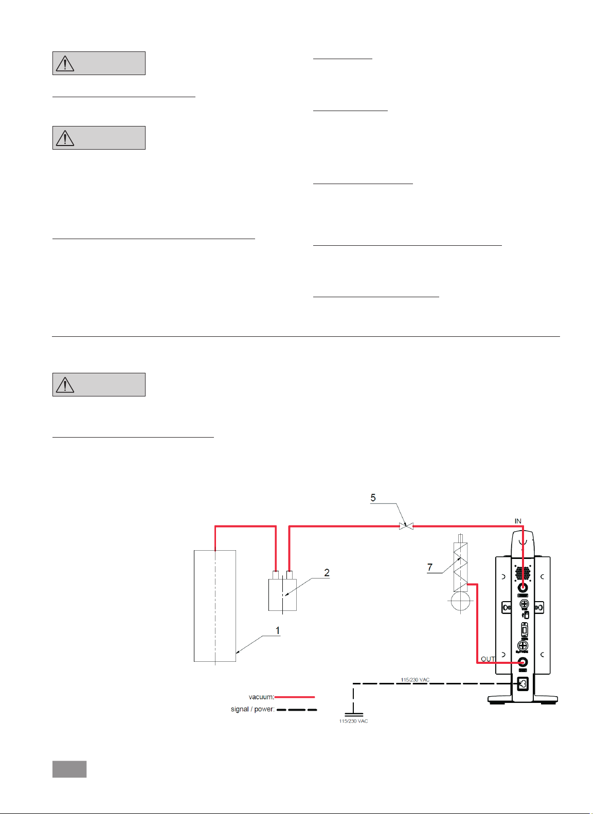
Two-position control:
IKA Vacstar digital in standalone operation
Vacuum created without a controller through simple suction, no
vacuum target value control possible.
The pump speed can be changed by manually setting the speed
using the rotating/pressing knob (C) of the vaccum pump.Manual
1 Recipient (load, e.g. rotary
evaporator, reactor)
2 Vacuum separator (e.g. Woulff
bottle)
5 Vacuum valve/ball valve
7 Emission condenser
Observe the operating instructions
for the devices.
activation of the vacuum valve or ball valve.
Rough vacuum control is possible, for example, with the vacuum
control valves VCV 1 and VCV 2, by mixing in air from outside.
10
Page 11
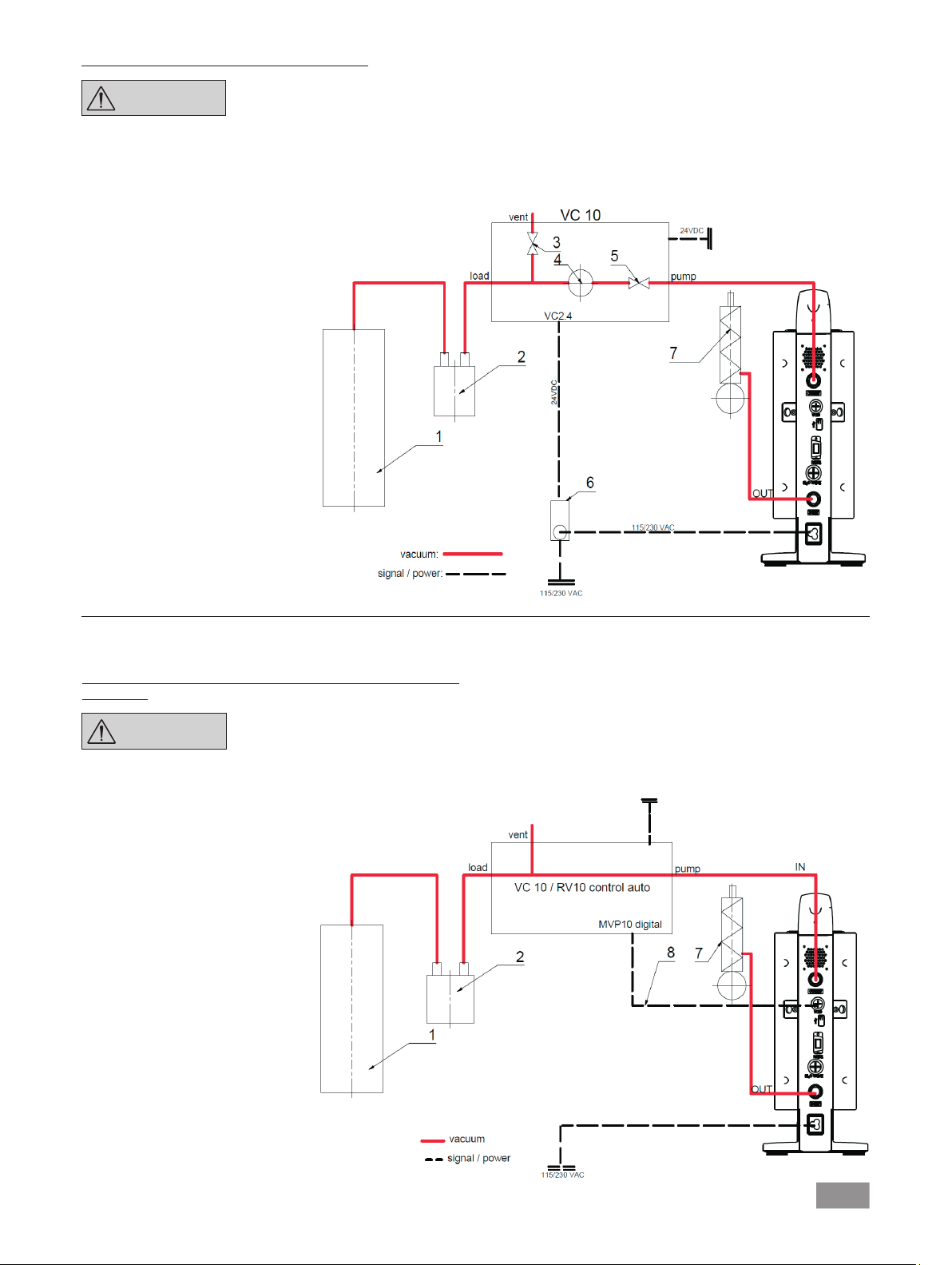
IKA Vacstar digital with vacuum controller VC 10
NOTE
When the target value is reached, the suction line is closed by the
vacuum valve integrated in the VC 10. The pump speed can be
changed by manually setting the speed.
1 Recipient (load, e.g. rotary
evaporator, reactor)
2 Vacuum separator (e.g. Woulff
bottle)
3 Vent valve
4 Pressure sensor
5 Vacuum valve/ball valve
6 Pump cut-out unit VC 2.4
7 Emission condenser
Cannot
water valve RV 10.5001 in conjunction
with VC 2.4.
Refer to the operating instructions
for the vacuum controller VC 10!
be operated with optional
When using the optional pump cut-out unit
VC 2.4 (ref. 6) the pump is switched off when the target value is
reached (operating mode B).
This
device configuration
cut-out unit VC 2.4. The pump runs on. For good control, the
pump should be operated at a low speed.
is also
possible without
the pump
Speed regulation
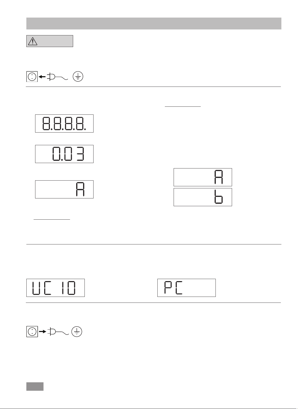
IKA Vacstar digital with vacuum controller VC 10 or rotary
RV 10 auto
NOTE
Automatc setting of the operating mode “Speed regulation” as
soon as the
connects the pump
1 Recipient (load, e.g. rotary
evaporator, reactor)
2 Vacuum separator (e.g.
Woulff bottle)
7 Emission condenser
8 Analogue connecting cable
MVP 10.100
analogue connecting cable
Observe the operating instructions
for the devices.
MVP 10.100 (ref. 8)
with the vacuum controller or rotary evaporator.
evaporator
When the target value is reached, the pump speed is
matically
value is reached, the pump applies
rate of the vacuum system. Automatic boiling point recognition
is possible.
reduced to a minimum of “0 rpm”. Once the target
suction according to the
24 VDC
115/230 V
auto-
leakage
11
Page 12
Commissioning
NOTE
Check if the voltage specified on the type plate matches the available mains voltage. If these conditions are met, the device is ready
for operation when it is plugged in to the mains.
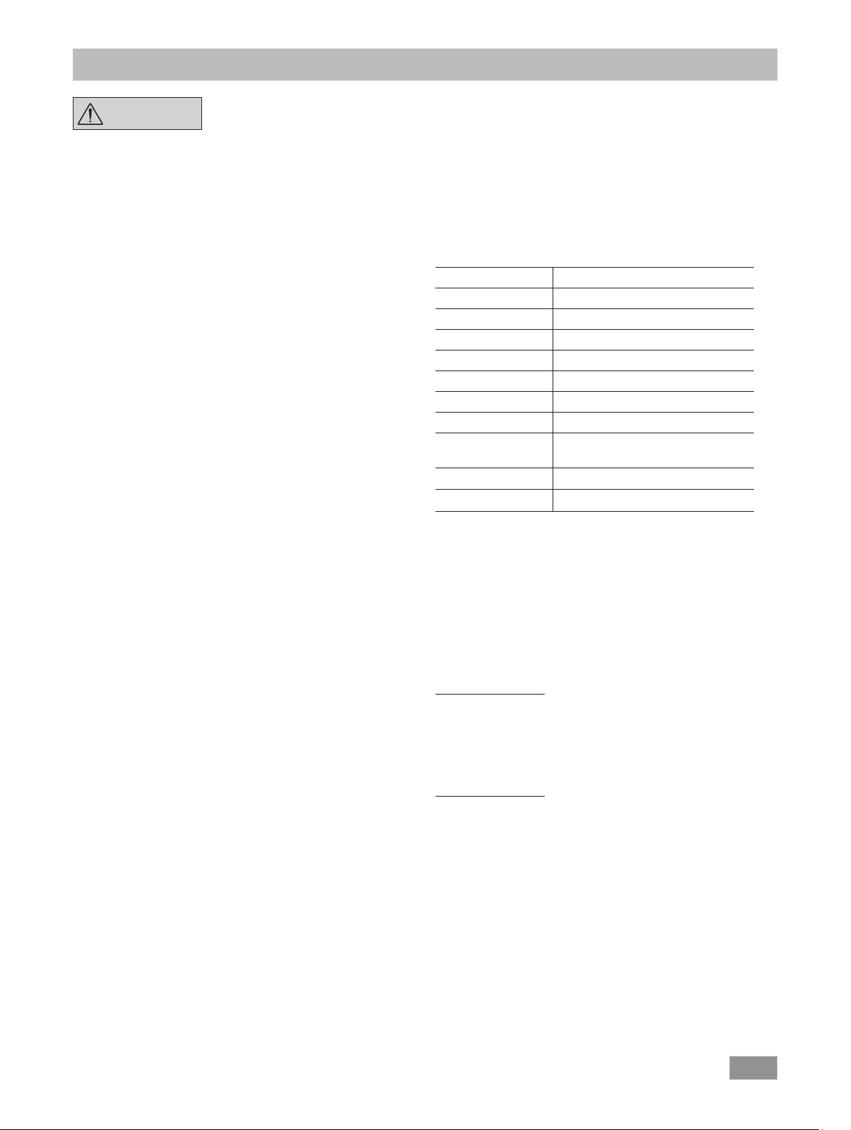
Switching on
1. Switch on the device using the main switch (D). All display
sements are shown to enable a visual check.
2. Software version number display (e.g. vers. 1.00).
3. Operating mode display (A; B). (Factory setting: Operating
mode A)
Observe the operating instructions
for the devices.
The socket used must be earthed
(grounded contact).
Otherwise safe operation is not guaranteed or the device may be
damaged.
Observe the ambient conditions indicated under “Technical data”.
Operating mode B:
In this operating mode, the set target value is saved when the
current run comes to an end or the device is switched off, and
the value can be changed.
Operating mode B is required particularly in combination with
the pump cut-out unit VC 2.4.
Automatic restart after mains power is cut off.
Changing operating mode:
1. Press the rotating/pressing knob (C) and switch on the
device at the main switch (D) at the same time to change
between the two operating modes.
The operating mode can be changed when you switch on the
device.
Operating mode A:
In this operating mode, the set target value is not saved when
the current run comes to an end or the device is switched off.
No automatic restart after mains power is cut off.
Switching on with several interfaces
If the pump is operated via the analogue connecting cable MVP
10.100 with the vacuum controller VC 10 or the rotary evaporator
RV 10 auto, “VC 10” is shown on the display.
Switching off
Switch off the device using the main switch (D).
Unplug the appliance from the
mains socket to disconnect it from
the mains.
In standalone operation or two-position operation in combination
with the vacuum controller VC 10 the target speed can be set by
turning the rotating/pressing knob (C). Push to start the pump and
push again to stop it. A flashing light on the display (B) indicates
when the device is running.
If the vacuum controller is connected to a PC, “PC” is shown on
the display (B).
12
Page 13
Interfaces and outputs
NOTE
The device can be operated in “Remote” mode via an RS232 or
USB interface using the laboratory software labworldsoft
232 interface (M) at the back of the device is fitted with a 9-pole
SUB-D jack which can be connected to a PC. The pins are assigned
serial signals.
USB Interface
The Universal Serial Bus (USB) is a serial bus system which allows
the device to be connected to the PC. Devices that support USB
can be connected to each other whilst
plugging) and provide automatic
devices and their properties.
Use the
USB interface
operation in “Remote” mode and for updating the firmware using
the “Firmware update tool”.
Installation
Before the device is connected with the PC using the USB data
cable, the USB driver must be installed.
The USB driver can be downloaded from the website:
Serial interface RS 232 (V 24)
Configuration:
• The functions of the interface circuit between the device and
the automation system
in the EIA standard RS232 as per DIN 66020 Part 1.
• Standard RS 232, corresponding to DIN 66259 Part 1 is valid
for the electric characteristics of the
assignment of signal states.
• Transmission process: Asynchronous character transmission
in start-stop operation.
• Transmission type: Full duplex.
• Character format: Character composition according to data
format in DIN 66022 for start-stop operation. 1 start bit, 7
character bits, 1 parity bit (even), 1 stop bit.
• Transmission speed: 9600 Bits/s.
• Data flow control: none
• Access method: Data transmission from the device to the
computer only occurs after a request from the computer.
Command syntax and format
The following points should be noted for the instruction set:
• Commands are generally sent from the computer (master) to
the device (slave).
• The device only responds to requests from the computer.
Even error messages are not send spontaneously from the
device to the computer (automation system).
• The commands are transmitted in captial letters.
• Commands
must be separated by at least one space (code: hex 0x20).
• Each individual command (including parameters and data)
and all responses are completed with CRLF (code: hex 0x20
hex 0x0d hex 0x0A) and can have a maximum length of 50
characters.
• The dot is used for decimal separators in a floating-point val-
ue (code: hex 0x2E).
and
Please comply with
requirements together with the
operating instructions and help
section
included with
they are running
recognition of the
in conjunction with
are a selection from the signals specified
interface
parameters,
as well as consecutive parameters,
the system
the software.
®
. The RS
connected
labworldsoft®
circuits and
(hot
for
The
details
given
of NAMUR (NAMUR recommendations for the design of electrical
plug-in connectors for analogue and digital signals in laboratory
MSR devices. Rev. 1.1).
The NAMUR commands and the additional IKA-specific
commands are only used as low-level
between the device and the PC. With an appropriate terminal or
communication program, these commands can
directly to the device.
NAMUR commands Function
IN_NAME Read device name
IN_PV_4 Read current speed value
IN_SP_4 Read rated speed value
OUT_SP_4 Adjust the rated speed value
START_4 Start evacuation
STOP_4 Stop evacuation
RESET Switch to normal operating mode
OUT_NAME Set device name
OUT_SP_42@n Setting WD safety limit speed with
OUT_WD1@m Watchdog mode 1
OUT_WD2@m Watchdog mode 2
“Watchdog” functions; monitoring of the serial data flow
If, once this function has been activated (see NAMUR commands),
there is no retransmission of the command from the computer
within the set time (“watchdog time”), the Evacuation function is
switched off in accordance with the set “watchdog” mode or is
returned to previously set target values. The data transmission may
be interrupted by, for example, a crash in the operating system,
a power failure in the PC or an issue with the connection cable
between the computer and the device.
“Watchdog” mode 1
If event WD1 should occur, the evacuation function is switched
off and ER2 is displayed. Set watchdog time to m (20- 1,500)
seconds, with watchdog time echo. This command launches the
watchdog function
time.
“Watchdog” mode 2
If there is an interruption in data communications (longer than the
set watchdog time), the speed target value is changed to the set
WD safety speed limit. The warning PC 2 is displayed. The WD2
event can be reset with
function.
Set watchdog time to m (20 - 1,500) seconds, with watchdog
time echo. This command launches the watchdog function and
must be transmitted within the set watchdog time.
above generally comply
set value echo
and must be transmitted within the
OUT_WD2@0 -
with the
recommendations
commands for communication
be transmitted
set watchdog
this also stops
the watchdog
13
Page 14
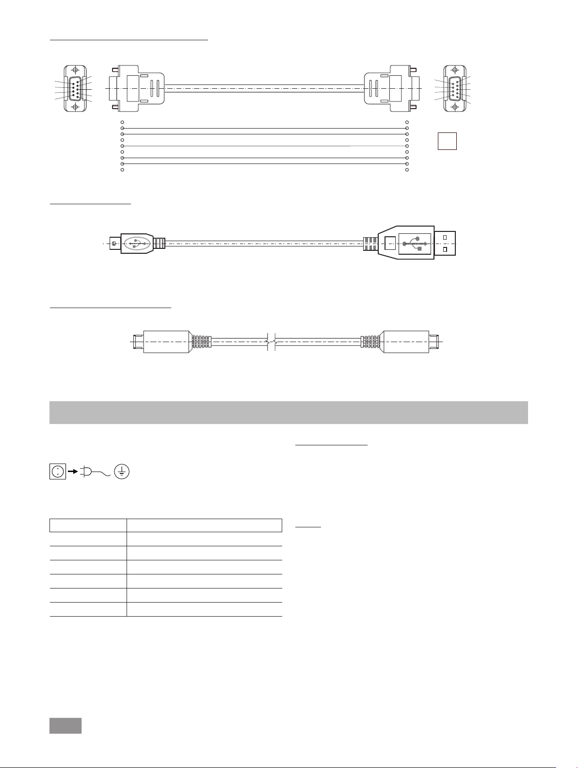
Accessories: PC 1.1 cable (device to PC)
9
9
Required for connecting the 9-pin socket to a PC.
6
7
8
9
1
2
3
4
5
RxD 2
TxD 3
GND 5
RTS 7
CTS 8
1
4
6
USB A - USB B cable
Required for connecting the USB interface (L) to a PC.
USB B
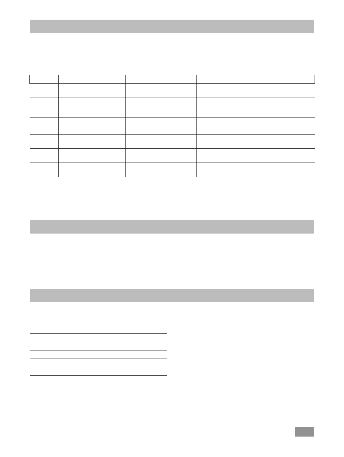
Connecting cable MVP 10.100
Required for connecting VC 10 and RV 10 auto with the diaphragm vacuum pump
A
IKA Vacstar digital
9
8
7
6
1
2 RxD
3 TxD
4
PC
5 GND
6
7 RTS
8 CTS
(speed operation).
5
4
3
2
1
USB A
Fig. 10
Fig. 11
Fig. 12
Maintenance and cleaning
The device is maintenance-free. However it is subject to natural
wear and tear on parts and their statistical failure rate.
Unplug from the mains before cleaning.
Only clean the IKA device using these IKA-approved cleaning
agents:
Dirt Cleaning agent
Dyes Isopropyl alcohol
Building materials Water containing detergent, isopropanol
Cosmetics Water containing detergent, isopropanol
Food Water containing detergent
Fuels Water containing detergent
Other materials Please ask IKA
• Wear protective gloves when cleaning the devices.
• Do not place electrical appliances into the cleaning agents for
cleaning purposes.
• Ensure no liquid enters the device during cleaning.
• Please consult with IKA before using any cleaning
decontamination methods not specifically recommended.
or
Ordering spare parts
When ordering spare parts,
please make sure
to indicate the
following:
• Device type
• Device manufacturing number; see rating plate
• Reference number and description of spare part; see spare
part diagram and list at www.ika.de.
Repairs
Please only send devices in for repair that have been
cleaned and are free of materials which might present
health hazards.
For this, use the “certificate of compliance” form which you
can obtain from IKA or can download a version for printing from
the IKA website www.ika.de
If your appliance requires repair, return it in its original packaging.
Storage packaging is not sucient. also use appropriate transport
packaging.
14
Page 15
Error codes
If an error occurs, this is shown in an error on the display (B), e.g. Error 4.
Proceed as follows:
• Switch the device off on the device switch,
• Take corrective measure,
• Switch device back on.
Error Cause Reason Solution
Error 3 Overheat The pump does not run Switch off the pump, disconnect it from the mains, let
Error 4 Motor blocked/overload The pump does not run Switch off the pump, disconnect it from the mains
Error 8 Hall sensor defective The pump does not run Service
Error 9 BLP self-test/EEPROM error The pump does not run Service
No display Pump diaphragm defective Minimum pressure and suction
rate are not achieved
No display Diaphragm valve defective Minimum pressure and suction
rate are not achieved
No display Liquid in the pump chambers Minimum pressure and suction
rate are not achieved
In the event that the fault cannot be eliminated using the measures described or another error code is displayed:
• Please contact the Service Department,
• Send the device and a brief description of the fault.
it cool down.
Let the pump cool down.
Ventilate the vacuum system to normal pressure.
Service
Request a maintenance kit
Service
Request a maintenance kit
Let the pump run dry (no-load operation)
• Vacuum controller IKA VC 10
• Vacuum control valve IKA
• Check valve IKA VC 10.300
• Vacuum hose IKA VH.SI.8
• PC 1.1 cable (RS 232)
Name Material
Connection spigot PPS
Connection piece PPS
Distributor PPS
Head piece PPS
Diaphragm valve FFPM
Diaphragm NBR/PTFE
Clamp PPS
VCV 1 and VCV 2
Accessories
• Maintenance kit
• Vacuum safety emission condenser VSE 1
• Woulff bottle/water valve set VSW1
For further accessories see www.ika.de
Product contact parts
15
Page 16

Technical data
Base unit Value
Delivery capacity max. m³/h 1.32
Delivery capacity max. L/min 22
Final pressure mbar 2
Suction steps 4
Cylinder 4
Connection diameter suction side mm 8
Connection diameter pressure side mm 8
Gas ballast valve no
Inlet pressure min. mbar 2
Inlet pressure max. mbar 1030
Boiling point recognition no
Solvent library no
Two-position control yes
Analogue speed-vacuum control yes
Speed setting option rotating/pressing knob
Speed min. rpm 285
Speed max. rpm 1200
Display LED
Vacuum sensor no
Vent valve no
Condensate separator no
Emission condenser no
Volume at minimum pressure dB(A) 54
Product contact material PTFE, FFPM, PPS, NBR
Housing material Cast alu, coated
Appropriate for clean room no
Explosion-proof no
Width mm 150
Depth mm 370
Height mm 375
Weight kg 11.5
Permitted ambient temperature min. °C 5
Permitted ambient temperature max. °C 40
Permitted relative humidity % 80
Protection class according to DIN EN 60529 IP 20
RS 232 interface yes
USB interface yes
Analogue output no
Voltage V 100-240
Frequency Hz 50/60
Power consumption W 130
Standby power consumption W 1.5
DC VDC 24
16
Page 17

Base unit Value
Protection class II
Overvoltage category I
Degree of contamination 1
Use above max. sea level m 2000
Firmware update yes
Subject to technical changes
17
Page 18

18
Page 19

Traduction
Table des matières
Structure de l’appareil ............................................................................................................................................................... 2/3
Déclaration de conformité ......................................................................................................................................................... 19
Explication des symboles ........................................................................................................................................................... 19
Garantie .................................................................................................................................................................................... 19
Consignes de sécurité ............................................................................................................................................................... 20
Déballage ................................................................................................................................................................................. 21
Utilisation conforme .................................................................................................................................................................. 22
Informations utiles .................................................................................................................................................................... 22
Installation ................................................................................................................................................................................ 23
Mise en service ......................................................................................................................................................................... 24
Interfaces et sorties ................................................................................................................................................................... 27
Entretien et nettoyage............................................................................................................................................................... 28
Messages d’erreurs ................................................................................................................................................................... 29
Accessoires ............................................................................................................................................................................... 29
Pièces en contact avec le produit .............................................................................................................................................. 29
Caractéristiques techniques ....................................................................................................................................................... 30
FR
Page
Déclaration de conformité
Nous déclarons, sous notre seule responsabilité, que ce produit est conforme aux dispositions des directives 2014/35/UE, 2006/42/CE,
2014/30/UE e
t 2011/65/UE ainsi qu’aux normes et documents normatifs suivants:
EN 61010-1, EN
60529
, EN 61326-
1 et EN ISO 12100.
Explication des symboles
DANGER
AVERTISSEMENT
PRUDENCE
REMARQUE
Situation (extrêmement) dangereuse dans laquelle le non-respect des consignes de sécurité peut causer la
mort ou des blessures graves.
Situation dangereuse dans laquelle le non-respect des consignes de sécurité peut causer la mort ou des
blessures graves.
Situation dangereuse dans laquelle le non-respect des prescriptions de sécurité peut causer des blessures
graves.
Indique par exemple les actions qui peuvent conduire à des dommages m
atéri
els.
Garantie
Conformément aux conditions de vente et de livraison d’IKA, la
garantie s’étend sur une période de 24 mois. En cas de demande
de garantie, s’adresser au distributeur. Il est également possible
d’expédier l’appareil accompagné de la facture et de la raison de
la réclamation directement à notre usine. Les frais de port sont à
la charge du client.
La garantie ne s’étend pas aux pièces d’usure et n’est pas valable
pour les erreurs causées par une manipulation non conforme, un
entretien et une maintenance insusants ou le non-respect des
instructions du présent mode d’emploi.
19
Page 20

Consignes de sécurité
Pour votre sécurité
REMARQUE
• Conservez
à tous.
• Veillez à
l’appareil.
• Respectez les consignes de sécurité, les directives, ainsi que
les mesures de prévention des accidents.
• L’appareil et ses
personnes ou les animaux.
Structure de l’appareil
le
mode d’emploi
ce que seul un
DANGER
• Mettez l’appareil en place conformément au chapitre «Installation», et raccordez les câbles et les interfaces comme décrit.
• Placez l’appareil sur une surface stable, plane et non inflammable.
• Ne travaillez jamais
fectueux.
Lisez entièrement le mode
avant la mise en service et
les consignes de sécurité.
de manière à ce qu’il soit accessible
personnel formé travaille avec
pièces ne doivent pas être utilisés sur les
La pompe à vide IKA Vacstar digital
n’est pas conçue pour être installée
dans les zones à atmosphère explosive.
avec un appareil mal raccordé ou dé-
d’emploi
respectez
DANGER
• Ne soumettez pas au vide des parties du corps de personnes
ou d’animaux.
• N’utilisez pas l’appareil sous l’eau ou sous terre.
• Placez la pompe à vide dans une hotte de laboratoire adaptée
et fonctionnelle ou raccordez-la à une conduite d’évacuation
de la fumée. Veillez à ne pas couder la conduite d’évacuation! La longueur de la conduite d’évacuation ne doit pas
dépasser 2m!
• Évitez la formation de mélanges explosibles, raccordez éventuellement un gaz inerte pour la ventilation et/ou pour la dilution.
Portez votre équipement de protection
personnelle en fonction de la
classe de
en raison du danger présenté par
les projections de liquides et les
dégagements de gaz toxiques ou
inflammables!
danger du milieu à traiter,
Accessoires
• La sécurité du travail n’est garantie qu’en utilisant les
accessoires décrits au chapitre «Accessoires».
• Respectez attentivement
additionnels (p. ex. évaporateur rotatif, contrôleur de vide)
avec lesquels la pompe à vide
• La pression à l’entrée
1100mbar.
Utilisation de l’appareil
et à la sortie du gaz ne doit pas dépasser
DANGER
AVERTISSEMENT
le mode d’emploi des appareils
IKA Vacstar digital
La sortie de vapeurs de solvants
dans l’atmosphère peut être évitée
avec un condenseur d’évacuation
placé en aval.
La pompe à vide n’est pas conçue
pour une utilisation avec les
substances auto-inflammables,
les
substances inflammables
en l’absence d’apport d’air ou les
substances explosives.
Ne faites jamais fonctionner la
pompe quand elle
Sinon, il y a un risque de blessures
graves en cas d’insertion de la
main dans des pièces rotatives!
L’inhalation ou le contact avec des
milieux tels que les liquides
toxiques
pulvérisation, les vapeurs, les
poussières ou les substances
biologiques peut être dangereux
pour la santé de l’utilisateur.
Assurez-vous
tous les raccords lors de
de ces milieux.
, les gaz, les brouillards de
de l’étanchéité de
fonctionne.
est ouverte.
l’utilisation
• Les éléments élastiques peuvent être comprimés sous l’effet
du vide.
• Ut
ilisez exclusivement des conduites flexibles.
• En cas de panne électrique, suivez vos mesures d’urgence et
assurez-vous de placer l’installation dans un état sûr (voir le
chapitre Mise en service
• La pompe à vide IKA Vacstar digital doit être exploitée exclusivement dans les conditions décrites au chapitre «Caractéristiques techniques».
• Empêcher le dégagement des substances susmentionnées.
Prenez des mesures de protection pour le personnel et l’environnement.
• Tenez compte des éventuelles interactions ou réactions
chimiques ou physiques, lors de la manipulation de milieux
sous pression réduite et température accrue.
• Des processus électrostatiques peuvent se produire entre le
milieu et l’appareil et engendrer un danger.
• En raison du taux de fuite résiduel de l’appareil, un relargage
du milieu peut se produire.
• Avant la mise en service, vérifier que toutes les pièces du carter sont présentes et fixées sur l’appareil.
• Ne soulevez pas la pompe si la poignée est desserrée et si la
vis de sécurité de la poignée (E) est dévissée ou manquante!
• Activez la pompe uniquement si la pompe est à la verticale.
• Reliez les raccords de flexibles (INLET-OUTLET) et les interfaces conformément aux inscriptions sur l’appareil et aux indications du mode d’emploi.
• Assurez-vous que la température du milieu évacué se trouve
sous la température d’inflammation. Le processus de pompage (compactage) fait encore monter la température du
milieu.
, Mode de fonctionnement).
20
Page 21

• Attention, des vapeurs contenant des solvants peuvent être
aspirées dans la pompe!
• N’utilisez pas la pompe pour générer de la pression!
• Respectez la pression autorisée côté entrée et côté sortie, voir
le chapitre «Caractéristiques techniques».
• Une régulation/un rétrécissement du flux de gaz n’est autori-
Pour protéger l’appareil
AVERTISSEMENT
PRUDENCE
• Pour débrancher l’appareil du secteur, tirez sur la fiche secteur de l’appareil.
• La prise de courant utilisée pour le câble secteur doit être
facile d’accès.
• Les caches et les pièces qui peuvent être retirés de l’appareil
sans outillage, doivent être remontés sur l’appareil pour garantir la sécurité, dès lors qu’aucun autre raccordement n’a
lieu à cet endroit. Ceci permet d’éviter l’infiltration de liquides
ou la pénétration de corps étrangers.
• Les liquides aspirés par inadvertance peuvent être évacués en
aspirant de l’air.
Assurez-vous de la compatibilité
des substances utilisées avec l’appareil avec les matériaux des
pièces de l’appareil en contact
avec le produit, voir le chapitre «
Pièces en contact avec le produit ».
L’indication de la tension sur la
plaque signalétique doit coïncider
avec la tension du secteur.
sé(e) que dans la conduite côté aspiration!
• Utilisez plusieurs électrovannes ou clapets antiretour dans la
conduite d’aspiration en cas d’utilisation de plusieurs dispositifs de charge.
• En cas d’utilisation d’un condenseur d’émissions, veillez à
l’écoulement libre du liquide de refroidissement!
• Évitez les coups et les chocs sur l’appareil.
• Seul le personnel qualifié (autorisé) est habilité à ouvrir l’appareil
• L’appareil ne doit pas être modifié sans l’autorisation d'IKA.
• Pour permettre un refroidissement suffisant de la pompe à
vide IKA Vacstar digital, les fentes d’aération du carter ne
doivent pas être couvertes.
• Pour la remise en état, utilisez exclusivement des pièces détachées d’origine, afin de garantir la fiabilité de l’appareil.
• Tenir compte de la condensation de l’eau à l’intérieur et à
l’extérieur de l’appareil. Réchauffer d’abord l’appareil s’il
vient d’un environnement froid.
• Ne raccordez jamais la pompe à vide à un bain de thermostatisation.
• Veillez à ce qu’aucun corps solide et/ou liquide ne pénètre
dans la membrane de la pompe à vide IKA Vacstar digital via
la conduite d’aspiration. Cela endommagerait la membrane
et d’autres pièces internes à la pompe. Le débit s’en trouverait réduit et la pression finale ne serait plus atteinte. Desdépôts peuvent apparaître à l’intérieur de l’appareil, ce qui en
réduit la durée de vie et provoque des fuites!
Déballage
Déballage
• Déballez l’appareil avec précaution.
• En cas de dommages, établissez immédiatement un constat
correspondant (poste, chemin de fer ou transporteur).
Contenu de la livraison
Pompe à vide à membrane
Câble secteur d’ordina-
teur portable
Câble USB A - USB B
Flexible de vide 1m
IKA Vacstar digital
A
Silencieux
Câble de connexion
MVP 10.100
Mode d’emploi
Carte de garantie
21
Page 22

Utilisation conforme
Utilisation
AVERTISSEMENT
La pompe à vide à membrane de laboratoire
à générer du vide
laboratoire.
Pour la régulation définie du vide, un régulateur de vide
IKA VC 10
Domaine d’utilisation (uniquement en intérieur)
L’appareil peut être utilisé dans toutes les zones résidentielles et
tous les autres secteurs.
L’utilisateur n’est plus protégé:
• si l’appareil est utilisé avec des accessoires non fournis ou non
ou un évaporateur rotatif IKA RV 10 auto est nécessaire.
recommandés par le fabricant!
Ne pas utiliser l’appareil pour:
- L’évacuation d’espaces vitaux
biologiques,
-
L’évacuation de volume de gaz
explosifs, corrosifs ou autres,
- Le passage/l’utilisation
L’appareil n’est pas adapté pour:
- le pompage d’objets
- le pompage de liquides
- les zones à atmosphère explosive
- sous l’eau
- en extérieur
IKA Vacstar digital sert
en combinaison avec d’autres appareils
de liquides!
supplémentaire
de
Fonctionnement individuel
La pompe à vide peut fonctionner sans contrôleur.
La vitesse de rotation réglable permet d’ajuster le débit.
manière générale, plus le volume à évacuer est petit, plus la vitesse
de rotation doit être faible. La pression finale n’est pas régulée.
Fonctionnement avec des accessoires
En combinaison avec les accessoires recommandés par IKA, la
pompe à vide
sur une pression finale définie, p. ex. pour le fonctionnement d’un
évaporateur rotatif IKA.
En outre, elle sert aux opérations
filtration ou de séchage en laboratoire.
Avec un contrôleur de vide adapté
évaporateur rotatif
fonctionner
automatique du point d’ébullition, des courbes pression-temps
ou des programmes provenant de la bibliothèque des solvants
peuvent être exécutés.
Utilisation prévue: Appareil de table
• si des modifications ont été apportées par un tiers à l’appareil
ou à des pièces de l’appareil!
• si l’appareil est utilisé sans respecter les
IKA Vacstar digital
(p. ex. RV 10 auto) la Vacstar digital
de manière automatisée, ainsi une détection
est adaptée à l’évacuation régulée
classiques de séparation, de
(p. ex. VC 10) ou avec un
consignes
de sécurité!
De
peut
DANGER
PRUDENCE
Informations utiles
La sortie de vapeurs de solvants
dans l’atmosphère peut être évitée
avec un condenseur d’évacuation
placé en aval.
Une prudence particulière s’impose lors des travaux avec des mélanges gazeux qui contiennent des
gaz condensables (p. ex. vapeur
d’eau ou solvants). L’utilisation des
pompes à membrane avec de tels
gaz entraîne leur condensation
dans le flux d’air de la pompe. Ceci
génère une pression dans la
chambre de vide qui réduit la performance et la durée de vie des
membranes et soupapes.
Si du liquide ou du condensat pénètre dans les chambres de vide, la
pression de service minimale indiquée n’est plus atteinte.
Pour protéger les soupapes intérieures et les membranes du liquide, utilisez un séparateur de
condensat placé en amont (par
exemple: flacon de Woulfe).
PRUDENCE
REMARQUE
Les pompes à vide à membrane sont des pompes d’évacuation
oscillantes. Les membranes génèrent par expansion du volume
dans la chambre de vide une dépression qui a pour effet l’arrivée
d’air dans la chambre. La compression qui suit chasse l’air de la
chambre de vide. La commutation entre l’entrée et la sortie est
commandée via des soupapes à membrane.
L’unité physique de la pression est 1 Pascal [Pa].
On utilise aussi couramment l’unité millibar [mbar].
1 mbar = 100 Pa
1 bar = 10
1 Pa = 10
1 Pa = 0,01 mbar
5
-5
Pa
bar
De manière générale, il est recommandé de laisser tourner la pompe
à vide à la fin d’un processus
(marche à vide pendant 3 à 5minutes maxi) afin d’évacuer les
éventuels résidus présents dans la
pompe.
Pour ce faire, ventilez le récipient
si besoin.
En mode manuel, retirez la conduite
d’aspiration.
Tenez compte des instructions
d’utilisation des appareils concernés.
22
Page 23

Dans la technique de vide, on distingue différents secteurs.
5
Vide grossier: 10
Vide fin: 10² à 10
Vide poussé: 10
Ultravide < 10
à 10² Pa (1000 à 1 mbar)
-1
Pa ( 1 à 10-3 mbar)
-1
à 10-5 Pa (10-3 à 10
-5
Pa ( < 10
-7
-7
mbar)
mbar)
Les mouvements périodiques de la membrane génèrent un vide à
l’entrée de la pompe. Les pompes à vide à membrane fonctionnent
en vide grossier jusqu’à 10
2
Pa. Ces pompes ne permettent pas
d’obtenir des pressions plus faibles.
Pour générer du vide fin, du vide poussé et de l’ultravide, il faut
utiliser des pompes à vide étanches à l’huile, des pompes à vis, des
pompes à diffusion ou des pompes turbomoléculaires. Les pompes
à vide à membrane servent souvent ici de pompes d’entrée.
La compression et la détente de l’air génèrent un bruit. La pompe
est d’autant plus silencieuse que la quantité d’air transporté est
faible. Ceci a pour conséquence que le bruit de fonctionnement
en mode normal baisse parallèlement à la pression.
Un flexible d’évacuation à silencieux sert également à la réduction
du bruit.
En mode automatique à vitesse de rotation régulée, la pompe réduit sa vitesse de rotation quand elle atteint la valeur théorique.
Si le taux de fuite du système est faible, la vitesse de rotation est
même régulée sur «zéro».
En cas de combinaison avec le contrôleur de vide VC 10 ou l’évaporateur rotatif à contrôleur de vide intégré RV 10 auto, la pompe
peut aussi bien servir à la «régulation à deux points» (commande
par soupape) qu’à la «régulation analogique de la vitesse de rotation» du vide.
Régulation à deux points
Une fois la valeur de consigne atteinte, la conduite d’aspiration est
fermée. En raison du délai minimal entre
pression et la comparaison avec la valeur
la détection de la
valeur de
théorique pour commuter
une vanne de vide ainsi que la puissance d’aspiration du système
générant le vide, la valeur théorique définie n’est pas tout à fait
atteinte.
taux de fuite naturel,
Si la pression augmente encore dans le système
la vanne ouvre
la conduite d’aspiration.
en raison du
Illustration schématique d’une régulation du vide à deux points
mbar
t
Régulation analogique de la vitesse de rotation
Avec cette régulation, la vitesse de rotation de la pompe, et donc
la puissance d’aspiration, est réduite à mesure que la valeur de
pression
mesurée s’approche
de la valeur théorique.
Une fois la valeur
de consigne atteinte, la pompe ne tourne plus qu’en fonction du
taux de fuite du système. Cette régulation se caractérise par un
fonctionnement silencieux, la précision de la régulation du vide
et une grande longévité des pièces mobiles de la pompe. Ce type
de régulation permet la détection automatique précise du point
d’ébullition, ce qui signifie que le système cherche et maintient en
mode automatique le point d’ébullition du solvant.
Illustration schématique d’une régulation du vide asservie au régime
mbar
t
REMARQUE
Installation
Tenez compte de la consigne générale de toujours relier le récipient
(charge/récipient à vide/refroidisseur de verre) à la conduite d’aspiration en son point le plus haut.
Vous réduisez ainsi le risque d’infiltration de liquide dans la pompe à
vide.
La présence de liquide dans les
chambres de la pompe impacte négativement les caractéristiques de
la pompe.
Reliez les raccords de flexibles
(INLET-OUTLET) et les interfaces
conformément aux inscriptions
sur la pompe et aux indications du
mode d’emploi.
Les raccords sont de type olive de flexible. Si besoin, fixez les
flexibles avec des colliers.
Installez les flexibles de manière à empêcher l’infiltration de
condensat dans la pompe.
Veiller à garantir l’entrée libre de l’air dans les fentes d’aération (H).
Installez dans la conduite d’aspiration un dispositif de séparation
du condensat (p. ex. flacon de Woulfe) devant le raccord d’aspiration de la pompe, pour éviter l’infiltration de liquide.
En cas d’aspiration de vapeurs de solvants, un condenseur d’émissions, installé en aval de la pompe (accessoire), contribue à les
condenser et empêche leur relargage dans l’atmosphère.
23
Page 24

Raccordement des interfaces
REMARQUE
O: Raccord de flexible d= 8 mm OUTLET
Utilisez ce raccord pour relier un flexible de vide au condenseur
d’émissions ou installer un silencieux à l’extrémité du flexible.
REMARQUE
K: Prise contrôleur de vide VC 10 (mini DIN)
Vous pouvez relier la pompe à vide et le contrôleur de vide VC 10
ou l’évaporateur rotatif RV 10 auto avec le câble de connexion
analogique MVP 10.100 pour obtenir une régulation précise du
vide asservie au régime.
Le contrôleur de vide détecte la pompe et commute sur le mode
de régulation du vide asservie au régime. La régulation analogique
à deux points est désactivée.
Tenez compte des raccords concernés (voir Fig. 1).
Installez l’extrémité du flexible
dans la hotte de laboratoire!
Veillez à une évacuation libre côté
pression!
Côté pression, n’utilisez pas
d’étrangleur et ne refermez pas l’évacuation ! Reliez la conduite d’évacua
tion de la fumée à ce raccord.
L: Port USB
Reliez la pompe à vide IKA Vacstar digital à un PC avec le câble
USB A - USB B. L’outil logiciel IKA FUT permet de charger d’éventuelles mises à jour du logiciel de l’appareil.
M: Port RS 232
Vous pouvez relier la pompe à vide IKA Vacstar digital à un PC,
via un câble d’interface RS 232. La pompe peut fonctionner avec
le logiciel d’appareils de laboratoire labworldsoft
avec d’autres appareils. Vous trouverez d’autres informations au
chapitre «Interfaces et sorties».
N : Prise vanne d’eau
Reliez la vanne d’étranglement d’eau optionnelle RV 10.5001 à la
pompe à vide à membrane. La vanne d’eau permet de piloter le
débit de l’eau vers le condenseur à émissions. La vanne s’ouvre dès
que la pompe est activée.
I: Raccord de flexible de la conduite d’aspiration d= 8 mm INLET
Reliez la conduite d’aspiration à ce raccord.
Utilisez ce raccord pour relier un flexible de vide au récipient
(refroidisseur d’évaporateur rotatif, raccord de laboratoire, etc.).
P: Prise pour le câble réseau
Comparez l’indication de tension sur la plaque de puissance à la
tension réseau disponible. Raccordez le câble réseau à l’alimentation en tension.
®
en combinaison
Configuration
REMARQUE
Régulation à deux points:
IKA Vacstar digital en mode individuel
Génération de vide sans contrôleur par simple aspiration, aucune
régulation possible de la valeur théorique de vide.
Il est possible de modifier manuellement la vitesse de la pompe
avec le bouton
1 Récipient (charge, p. ex. éva-
porateur rotatif, réacteur)
2 Séparateur de vide (p. ex.
flacon de Woulfe)
5 Vanne de vide/robinet à bois-
seau sphérique
7 Condenseur d’émissions
rotatif/
Respectez les modes d’emploi des
appareils.
poussoir
(C)
de la pompe à vide.
Actionnement
sphérique.
Une régulation grossière du vide est, p. ex., possible avec les
vannes de régulation VCV 1 et VCV 2 en ajoutant de l’air.
manuel de la vanne de vide ou du robinet à boisseau
24
Page 25

IKA Vacstar digital avec contrôleur de vide VC 10
REMARQUE
Une fois la valeur théorique atteinte, la conduite d’aspiration est
fermée via la vanne de vide intégrée dans le VC 10. Il est possible
de modifier manuellement la vitesse de la pompe.
1 Récipient (charge, p. ex. éva-
porateur rotatif, réacteur)
2 Séparateur de vide (p. ex.
flacon de Woulfe)
3 Vanne de ventilation
4 Capteur de pression
5 Vanne de vide/robinet à bois-
seau sphérique
6 Coupure de la pompe VC 2.4
7 Condenseur d’émissions
Fonctionnement impossible avec la
vanne d’eau optionnelle RV 10.5001
en combinaison avec le VC 2.4.
Respectez le mode d’emploi du
contrôleur de vide VC 10!
En cas d’utilisation de la coupure de pompe optionnelle VC 2.4
(rep. 6), la pompe se coupe une fois la valeur théorique atteinte
(mode de fonctionnement B).
Cette configuration de l’appareil est aussi possible sans le dispositif
de coupure de la pompe IKA VC 2.4. La pompe tourne. Pour une
bonne régulation, la pompe doit tourner à une vitesse réduite.
Régulation de régime
IKA Vacstar digital
rotatif TV 10 auto
REMARQUE
Réglage automatique du mode «Régulation du régime», dès lors
que le câble de connexion analogique MVP 10.100 (rep. 8) relie la
pompe au contrôleur de vide ou à l’évaporateur rotatif.
1 Récipient (charge, p. ex. éva-
porateur rotatif, réacteur)
2 Séparateur de vide (p. ex.
flacon de Woulfe)
7 Condenseur d’émissions
8 Câble de connexion analo-
gique MVP 10.100
avec contrôleur de vide VC 10 ou évaporateur
Respectez les modes d’emploi des
appareils.
Une fois la valeur théorique atteinte, le régime de la pompe est
réduit automatiquement à «0tr/min». Si la valeur théorique est
atteinte, la pompe tourne en fonction du taux de fuite du système.
La détection automatique du point d’ébullition est possible.
24 VCC
115/230 V
25
Page 26

Mise en service
REMARQUE
Vérifiez si la tension indiquée sur la plaque
tension du réseau disponible correspondent. Si ces conditions sont
remplies, l’appareil est prêt à fonctionner une fois le bloc secteur
branché.
Mise en marche
1. Allumez l’appareil au moyen de l’interrupteur principal (D).
Tous les segments d’achage apparaissent pour le contrôle
visuel.
2. Achage de la version du logiciel (exemple Vers. 1.00).
3. Achage du mode de fonctionnement défini (A; B).
(Réglage d’usinemode A)
Respectez les modes d’emploi des
appareils.
signalétique et la
La prise utilisée doit être mise à la
terre (contact à conducteur de
protection).
Sinon, le fonctionnement sûr n’est pas garanti ou l’appareil risque
de subir des dommages.
Veuillez tenir compte des conditions ambiantes stipulées dans les
«Caractéristiques techniques».
Mode de fonctionnement B:
Dans ce mode de fonctionnement, la valeur théorique définie
est mémorisée à la fin du processus en cours ou à la coupure
de l’appareil, la valeur peut être modifiée.
Le mode de fonctionnement B est nécessaire en particulier en
combinaison avec la coupure de pompe VC 2.4.
Redémarrage automatique après coupure de courant.
Modification du mode de fonctionnement:
1. En appuyant simultanément sur le bouton
(C) et en allumant l’appareil avec l’interrupteur principal
(D),
vous pouvez choisir l’un des deux modes de
fonctionnement.
rotatif/poussoir
Le mode de fonctionnement peut être modifié à la mise en
marche.
Mode de fonctionnement A:
Dans ce mode de fonctionnement, la valeur théorique définie
n’est pas mémorisée à la fin du processus en cours ou à la
coupure de l’appareil.
Pas de redémarrage automatique après la coupure de courant.
Mise en marche avec plusieurs interfaces
de
Si la pompe est reliée au contrôleur
rotatif RV 10
indique «VC 10»
Arrêt
Éteignez l’appareil au moyen de l’interrupteur principal (D).
avec le câble de connexion MVP 10.100, l’achage (B)
.
vide VC 10 ou à
Tirez
sur la
fiche secteur pour
débrancher l’appareil!
l’évaporateur
En fonctionnement individuel ou à deux points, en combinaison
avec le contrôleur de vide VC 10, il est possible de régler la vitesse
de consigne en tournant le bouton rotatif/poussoir (C). Appuyer
pour démarrer la pompe et appuyer à nouveau pour l’arrêter. Le
mode de régulation (appareil en marche) est indiqué par un point
clignotant à l’achage (B).
Si le contrôleur de vide est relié à un PC, l’écran ache (B) «PC».
26
Page 27

Ports et sorties
REMARQUE
L’appareil peut fonctionner en mode «Remote» par les interfaces
RS 232 ou USB avec le logiciel de laboratoire labworldsoft
port RS 232 (M) au dos de l’appareil, doté d’une prise SUB-D à
9 pôles, peut être relié à un PC. Les broches sont affectées de
signaux en série.
Port USB
L’USB (Universal Serial Bus)
permettant de relier l’appareil au PC. Les appareils dotés d’un port
USB peuvent être reliés entre eux au cours du fonctionnement
(hot-plugging)
être détectés automatiquement.
Le port USB sert en combinaison avec
fonctionnement en mode «Remote»
à l’aide de «l’outil de mise à jour de micrologiel».
Installation
Avant de relier l’appareil au PC avec un câble de données USB,
installer le pilote USB.
Le pilote USB peut être téléchargé à la page web suivante:
Port série RS232 (V 24)
Configuration :
• La fonction
système d’automatisation est une
spécifiés dans la norme EIA RS 232, conformément à la partie
1 de la norme DIN 66020.
• Les caractéristiques électriques des circuits
l’affectation des états des signaux sont régies par la norme
RS 232, conformément à la partie 1 de la norme DIN 66259.
• Procédure de transmission
caractères en mode start/stop.
• Type de transmission: Duplex intégral.
• Formats de caractères: Caractères conformes au format de
données stipulé dans la norme DIN 66022 pour le mode
Start-Stop. 1 bit de démarrage ; bits 7 caractères ; 1 bit de
parité (pair = Even); 1 bit d’arrêt.
• Vitesse de transmission: 9600 bits/s.
• Commande du flux de données: aucune
• Procédure d’accès: Un transfert de données de l’appareil vers
l’ordinateur n’est exécuté que sur requête de l’ordinateur.
Syntaxe de commande et format
Tenir compte des points suivants concernant le jeu d’instructions:
• Les commandes sont en général envoyées de l’ordinateur
(maître) à l’appareil (esclave).
• L’appareil n’émet que sur demande de l’ordinateur.
les messages d’erreur ne sont pas spontanément transmis par
l’appareil à l’ordinateur (système d’automatisation).
• Les commandes sont transmises en majuscules.
• Les commandes, paramètres et les suites de paramètres sont
séparés par au moins un espace (code hex 0x20).
• Chaque commande (y compris les paramètres et les données)
et chaque réponse se termine par CRLF (code: hex 0x20 hex
0x0d hex 0x0A) et a une longueur maximale de 50 caractères.
• Le séparateur décimal d’un nombre en virgule flottante est le
point (code : hex 0x2E).
et les
des câbles d’interface entre l’appareil et le
Respectez
requise, le mode d’emploi et les
aides du logiciel.
appareils
la configuration
est un
reliés, ainsi que
système de bus en série
leurs
labworldsoft® pour le
et la mise à jour du micrologiciel
sélection des signaux
: Transmission asynchrone de
minimale
caractéristiques,
d’interface et
Également,
®
. Le
Les explications précédentes sont globalement
recommandations du cercle de travail NAMUR (recommandations
NAMUR relatives à l’exécution de connexions électriques pour le
transfert de signaux analogiques et numériques à des appareils de
laboratoire individuels MSR. Rév. 1.1).
Les commandes NAMUR et les commandes
spécifiques à IKA servent uniquement de commandes de bas
niveau pour la communication entre l’appareil et le PC. Avec un
terminal ou un programme de communication
i
nstructions peuvent directement être transmises à l’appareil.
Commandes NAMUR
IN_NAME Lire le nom de l’appareil
IN_PV_4 Lire la vitesse actuelle
IN_SP_4 Lire la vitesse nominale
OUT_SP_4 Régler la vitesse nominale
START_4 Démarrer l’évacuation
STOP_4 Arrêter l’évacuation
RESET Commuter sur le mode normal
OUT_NAME Définir le nom de l’appareil
OUT_SP_42@n Réglage de la vitesse de sécurité du WD
OUT_WD1@m Mode Watchdog 1
OUT_WD2@m Mode Watchdog 2
Fonction «Watchdog», surveillance du flux de données
sériel
Si, après activation de cette fonction (voir les commandes Namur),
dans la période de surveillance définie («délai du watchdog»), la
commande n’est pas à nouveau transmise par le PC, la fonction
évacuation est arrêtée suivant le mode « Watchdog » réglé,
ou sont remises sur leurs valeurs théoriques précédentes. Le
transfert peut être interrompu par exemple par un bug du système
d’exploitation, une coupure de courant au niveau du PC ou une
déconnexion du câble de raccordement à l’appareil.
«Watchdog» – mode 1
Si l’événement WD1 se produit, la fonction d’évacuation est
désactivée et ER 2 s’ache. Régler le délai du Watchdog sur m
(20 à 1500) secondes, avec écho du délai du watchdog. Cette
commande déclenche la fonction watchdog et doit toujours être
envoyée dans le délai défini pour le watchdog.
«Watchdog» – mode 2
Si la communication des données est interrompue (plus longtemps
que le délai défini pour le Watchdog), la vitesse de consigne
est réglée sur la vitesse de consigne de sécurité WD définie.
L’avertissement PC 2 s’ache. L’événement WD2 peut être
réinitialisé avec OUT_WD2@0. Ceci arrête la fonction Watchdog.
Régler le délai du Watchdog sur m (20 à 1500) secondes, avec
écho du délai du watchdog. Cette commande déclenche la
fonction watchdog et doit toujours être envoyée dans le délai
défini pour le watchdog.
Fonction
avec écho de la valeur fixée
conformes aux
supplémentaires
approprié, ces
27
Page 28

Accessoires: Câble PC 1.1 (Device to PC)
9
6
7
8
9
Requis pour connecter la douille à 9 pôles à un PC.
1
2
3
4
5
1
RxD 2
TxD 3
4
GND 5
6
RTS 7
CTS 8
9
Câble USB A - USB B
Requis pour connecter le port USB (L) à un PC.
USB B
Câble de connexion MVP 10.100
Requis pour la connexion de VC 10 et RV 10 auto avec la pompe à vide à membrane
A
IKA Vacstar digital
9
8
7
6
1
2 RxD
3 TxD
4
PC
5 GND
6
7 RTS
8 CTS
(mode régime).
5
4
3
2
1
USB A
Fig. 10
Fig. 11
Fig. 12
Entretien et nettoyage
L’appareil est sans entretien. Il n’est soumis qu’au vieillissement
naturel des composants et à leur taux de panne statistique.
Débranchez la fiche secteur avant le
nettoyage.
Nettoyez l’appareil IKA uniquement avec les produits nettoyants
autorisés par IKA:
Type d’encrassement Produit de nettoyage
Colorants Isopropanol
Matériaux de construction Eau tensioactive, isopropanol
Cosmétiques Eau tensioactive, isopropanol
Aliments Eau tensioactive
Combustibles Eau tensioactive
Substances non mentionnées Consultez IKA
• Portez des gants de protection pour nettoyer les appareils.
• Ne jamais déposer les appareils électriques dans du produit
de nettoyage pour les nettoyer.
• Lors du nettoyage, aucune humidité ne doit pénétrer dans
l’appareil.
• En cas d’utilisation de méthodes de nettoyage et de décontamination autres que celles recommandées, interrogez IKA.
Commande de pièces de rechange
Pour la commande de pièces de rechange, fournir les indications
suivantes:
• Type d’appareil
• Numéro de fabrication de l’appareil, voir la plaque signalétique
• Référence et désignation de la pièce de rechange, voir
les illustrations et la liste des pièces de rechange sous
www.ika.de
Réparation
Veuillez n’envoyer à
la réparation que des appareils
nettoyés et exempts de substances toxiques.
Utilisez pour cela le formulaire «Certificat de régularité» fourni
par IKA ou imprimez le formulaire téléchargeable sur le site Web
d’IKA www.ika.de.
Si une réparation est nécessaire, retournez l’
emballage d’origine. Les emballages
de stockage
susants pour les retours. Utilisez en plus un
appareil
ne sont
emballage
dans son
de
transport
pas
adapté.
28
Page 29

Messages d’erreurs
Si une erreur survient, celle-ci est signalée à l’écran (B) par un code d’erreur, p. ex. Error 4.
Procédez alors comme suit:
• Arrêtez l’appareil en appuyant sur l’interrupteur,
• Prenez une mesure corrective,
• Rallumez l’appareil.
Défaut Cause Explication Mesure
Error 3 Surchauffe (overheat) La pompe ne tourne pas Couper la pompe, la débrancher et la
Error 4 Moteur bloqué/surcharge
(motor blocked/overload)
Error 8 Capteur d’effet Hall défectueux La pompe ne tourne pas Service (Entretien)
Error 9 Autotest BLP/Erreur EEPROM La pompe ne tourne pas Service (Entretien)
Pas d’achage Membrane de pompe défec-
tueuse
Pas d’achage Vanne à membrane défectueuse Pression et puissance d’aspiration
Pas d’achage Liquide dans les chambres de la
pompe
Si l’erreur ne peut pas être éliminée à l’aide des mesures décrites ou si un autre code d’erreur s’ache:
• Contactez le service d’assistance,
• Expédiez l’appareil avec une brève description de l’erreur.
La pompe ne tourne pas Couper la pompe, la débrancher
Pression et puissance d’aspiration
minimales non atteintes
minimales non atteintes
Pression et puissance d’aspiration
minimales non atteintes
laisser refroidir.
Laisser refroidir la pompe.
Purger le circuit de vide pour l’amener à
la pression normale.
Service (Entretien)
Demander le kit d’entretien
Service (Entretien)
Demander le kit d’entretien
Laisser la pompe tourner à sec (mode
marche à vide)
• Contrôleur de vide IKA VC 10
• Vanne de régulation du vide IKA VCV 1 et VCV 2
• Clapet anti-retour IKA VC 10.300
• Flexible de vide IKA VH.SI.8
• Câble PC 1.1 (RS 232)
Pièces en contact avec le produit
Dénomination Matériau
Manchon de raccordement PPS
Raccord PPS
Répartiteur PPS
Pièce de tête PPS
Vanne à membrane FFPM
Membrane NBR/PTFE
Élément de serrage PPS
Accessoires
• Kit d’entretien
• Condenseur d’émission de sécurité à vide VSE 1
• Kit flacon de Woulfe/vanne d’eau VSW1
Pour d’autres accessoires, voir www.ika.de
29
Page 30

Caractéristiques techniques
Unité Valeur
Débit maxi m³/h 1,32
Débit maxi l/min 22
Pression finale mbar 2
Étages d’aspiration 4
Vérins 4
Diamètre raccord côté aspiration mm 8
Diamètre raccord côté refoulement mm 8
Vanne de lest d’air Non
Pression d’entrée min. mbar 2
Pression d’entrée max. mbar 1030
Détection du point d’ébullition Non
Bibliothèque de solvants Non
Régulation à deux points Oui
Régulation analogique du vide asservie au régime oui
Possibilité de réglage de la vitesse Bouton rotatif/poussoir
Vitesse de rotation min. rpm 285
Vitesse de rotation max. rpm 1200
Achage LED
Capteur de vide Non
Vanne de ventilation Non
Séparateur de condensat Non
Condenseur d’émissions Non
Matériau en contact avec le produit PTFE, FFPM, PPS, NBR
Matériau du boîtier Revêtement fonte d’aluminium
Convient à l’utilisation en chambre propre Non
Protégé contre les explosions Non
Largeur mm 150
Profondeur mm 370
Hauteur mm 375
Poids kg 11,5
Température ambiante min. autorisée °C 5
Température ambiante max. autorisée °C 40
Humidité relative admissible % 80
Type de protection selon DIN EN 60529 IP 20
Port RS 232 Oui
Port USB Oui
Sortie analogique Non
Tension V 100-240
Fréquence Hz 50/60
Consommation de l’appareil W 130
Consommation de l’appareil en veille W 1,5
Tension continue VDC 24
30
Page 31

Unité Valeur
Classe de protection II
Classe de surtension I
Degré d’encrassement 1
Utilisation au-dessus du niveau de la mer max. m 2000
Mise à jour du micrologiciel oui
Valeurs déterminées.
Sous réserve de modifications techniques!
31
Page 32

32
Page 33

Traducción del idioma original
Índice de contenido
Diseño del aparato ................................................................................................................................................................. 2/3
Declaración de conformidad .................................................................................................................................................. 33
Explicación de símbolos.......................................................................................................................................................... 33
Garantía ................................................................................................................................................................................. 33
Advertencias de seguridad ..................................................................................................................................................... 34
Desembalaje .......................................................................................................................................................................... 35
Uso previsto ........................................................................................................................................................................... 36
Información importante ......................................................................................................................................................... 36
Instalación ............................................................................................................................................................................. 37
Puesta en servicio................................................................................................................................................................... 39
Interfaces y salidas ................................................................................................................................................................. 41
Mantenimiento y limpieza ...................................................................................................................................................... 42
Mensajes de error .................................................................................................................................................................. 43
Accesorios ............................................................................................................................................................................. 43
Partes en contacto con el producto ........................................................................................................................................ 43
Datos técnicos ....................................................................................................................................................................... 44
ES
Página
Declaración de conformidad
Declaramos bajo nuestra propia responsabilidad que este producto cumple las disposiciones de las directivas 2014/35/UE, 2006/42/CE,
2014/30/UE y
y EN ISO 12100.
2011/65/UE y es conforme con las normas y los documentos normativos siguientes:
EN 61010-1, EN
60529
, EN 61326-
1
Explicación de símbolos
PELIGRO
ADVERTENCIA
PRECAUCIÓN
NOTA
Situación (extremadamente) peligrosa en la que la no observación de las advertencias de seguridad puede
provocar la muerte o una lesión grave.
Situación peligrosa en la que la no observación de las advertencias de seguridad puede provocar la muerte
o una lesión grave.
Situación peligrosa en la que la no observación de las advertencias de seguridad puede provocar una lesión
leve.
Alude, por ejemplo, a acciones que pueden provocar
daños materiales.
Garantía
Según las condiciones de venta y suministro de IKA, la garantía
tiene una duración total de 24meses. Si se produce un caso de
garantía, póngase en contacto con su proveedor, o bien envíe el
aparato directamente a nuestra fábrica adjuntando la factura y
mencionando las causas de la reclamación.
correrán a su cargo.
Los
costes de
transporte
La garantía no se aplica a piezas de desgaste ni tampoco a errores
que tengan su causa en un manejo inadecuado o en un cuidado y
mantenimiento insuficientes que no cumplan lo dispuesto en estas
instrucciones de uso.
33
Page 34

Advertencias de seguridad
Para su protección
NOTA
• Guarde este manual de instrucciones en un lugar accesible
para todos.
• Asegúrese de que solo personal cualificado utilice el aparato.
• Observe las advertencias de seguridad, las directivas y las
normativas en materia de seguridad laboral y prevención de
accidentes.
• Ni el aparato ni sus componentes pueden utilizarse con personas ni animales.
Diseño del aparato
PELIGRO
• Emplace el aparato conforme a lo descrito en el capítulo “Instalación” y conecte los conductos de conexión y las interfaces
tal como describe en las instrucciones.
• Instale el aparato sobre una superficie estable, plana y no
inflamable.
Lea por completo las instrucciones
de uso antes de poner en servicio
el aparato y observe las advertencias de seguridad.
La bomba de vacío IKA Vacstar digital no está concebida para su instalación en zonas expuestas a riesgo de explosión.
PELIGRO
• No exponga partes del cuerpo de personas o animales al vacío.
• No utilice el aparato debajo del agua ni en sitios subterráneos.
• No trabaje nunca con aparatos que no estén conectados correctamente o que estén defectuosos.
• Coloque la bomba de vacío bajo una campana de laboratorio apropiada que funcione correctamente, o bien instale un
conducto de gases de escape. Tenga en cuenta a este respecto que el conducto de gases de escape no puede doblarse. La
longitud máxima permitida del conducto de gases de escape
es de 2 metros.
• Evite que se produzcan mezclas explosivas y, de ser necesario,
conecte gas inerte para la ventilación o la dilución.
Utilice el equipo de protección personal de acuerdo con la clase de
peligro del fluido que vaya a procesar, pues la salpicadura de líquidos
y la emisión de gases tóxicos o inflamables entrañan riesgos para el
usuario.
Accesorios
• La seguridad del funcionamiento solo está garantizada si se
utilizan los accesorios descritos en el capítulo “Accesorios”.
• Observe atentamente las instrucciones de uso de los aparatos
accesorios (como el evaporador rotativo o la bomba de vacío)
con los que se utiliza la bomba de vacío IKA Vacstar digital.
• La presión en la entrada y la salida de gas no puede superar
los 1100mbar.
Trabajo con el aparato
PELIGRO
ADVERTENCIA
La emisión de vapores de disolvente a la atmósfera puede evitarse
con un condensador de emisiones
postconectado.
La bomba de vacío no está concebida para el funcionamiento con
sustancias autoinflamables, ni
tampoco con sustancias que puedan inflamarse sin alimentación de
aire ni con sustancias explosivas.
No utilice la bomba si está abierta.
De lo contrario, existe el riesgo de
sufrir lesiones por la introducción
de la mano en los componentes
móviles internos.
La inhalación o el contacto con
fluidos como líquidos tóxicos, gases, aerosoles, vapores, polvos o
sustancias biológicas puede resultar perjudicial para la salud del
usuario. Así pues, siempre que manipule tales fluidos, asegúrese de
que todas las conexiones estén
bien apretadas y sean estancas.
• Los elementos elásticos pueden comprimirse si existe vacío.
• Utilice únicamente conductos de manguera flexibles.
• Observe las medidas de emergencia generales en el caso
de un corte en el suministro eléctrico y asegúrese de que el
aparato se utilice en un estado seguro (consulte el apartado
dedicado al modo de funcionamiento del capítulo “Puesta
en servicio”).
• La bomba de vacío IKA Vacstar digital solo puede utilizarse
en las condiciones descritas en el capítulo “Datos técnicos”.
• Del mismo modo, evite la liberación de las sustancias mencionadas antes. Mantenga medidas de protección apropiadas,
tanto para el personal como para el medio ambiente.
• Tenga en cuenta las posibles interacciones y las reacciones
químicas o físicas que pueden producirse cuando trabaje con
fluidos a presión reducida y temperatura elevada.
• Entre el fluido y el aparato pueden producirse procesos electrostáticos, lo que puede entrañar ciertos riesgos.
• Debido a la tasa de fuga residual del aparato, puede producirse una liberación de fluido.
• Antes de la puesta en servicio, asegúrese de que todos los
componentes del aparato estén presentes y fijados en el aparato.
• No eleve la bomba si el mango está suelto y el tornillo de
fijación del mango (E) se ha aflojado o falta.
• Encienda la bomba únicamente si la bomba se encuentra en
posición vertical.
• Conecte las conexiones de manguera (INLET/OUTLET) y las interfaces conforme a las etiquetas que aparecen en el aparato
y en el manual de instrucciones.
• Asegúrese de que la temperatura del fluido evacuado se encuentra por debajo de la temperatura de encendido de este.
Con el proceso de bombeo (compactación), aumenta también la temperatura del fluido.
34
Page 35

• Tenga en cuenta que los vapores que contienen disolventes
pueden aspirarse hacia la bomba.
• No utilice la bomba para generar presión.
• Tenga en cuenta la presión permitida en los lados de entrada
y salida; consulte el capítulo “Datos técnicos”.
• La regulación/estrangulación de la corriente de gas solo pue-
Para proteger el aparato
ADVERTENCIA
PRECAUCIÓN
• Para desconectar el aparato de la red eléctrica, basta con desenchufar el cable de alimentación de la toma de corriente.
• La toma de corriente para el cable de alimentación debe encontrarse en un lugar fácilmente accesible.
• Las cubiertas o piezas que se pueden quitar del aparato sin
utilizar herramientas se deben colocar de nuevo en el mismo
para garantizar un funcionamiento seguro, a menos que no
exista una conexión especial a este respecto, ya que, de este
modo, se evita la penetración de cuerpos extraños, líquidos,
etc.
• Los líquidos que se introducen de forma no deseada pueden
descargarse en el modo de marcha en vacío aspirando aire.
Asegúrese de que las sustancias
utilizadas con el aparato sean
compatibles con los materiales de
los componentes del aparato que
entran en contacto con el producto; consulte a tal fin el apartado
“Componentes que entran en contacto con el producto”.
La tensión especificada en la placa
de características debe coincidir
con la tensión de la red eléctrica.
de realizarse en el conducto del lado de aspiración.
• En el caso de que existan varios dispositivos de carga, utilice
las válvulas electromagnéticas o de retención en el conducto
de aspiración.
• Si va a utilizar un condensador de emisiones, tenga cuidado
con la salida libre de refrigerante.
• Evite que el aparato sufra golpes o impactos.
• La apertura del aparato debe correr a cargo exclusivamente
de personal técnico debidamente autorizado.
• El aparato no puede modificarse de ningún modo sin el permiso de IKA.
• Con el fin de garantizar una refrigeración suficiente de la
bomba de vacío IKA Vacstar digital, no cubra nunca las ranuras de ventilación de la carcasa.
• Utilice siempre componentes de repuesto originales para las
tareas de mantenimiento y reparación, pues solo así podrá
garantizar el funcionamiento fiable del aparato.
• Tenga cuidado con la condensación de agua que se forma
dentro y fuera del aparato. Si ha traído el aparato de un entorno frío, espere primero a que se atempere.
• No fije nunca la bomba de vacío por encima de un baño
calefactor.
• Asegúrese de que no puedan penetrar sustancias sólidas ni
líquidas en la membrana de la bomba de vacío IKA Vacstar
digital a través del conducto de aspiración de la bomba, pues
esto puede dañar dicha membrana y otros componentes internos de la bomba. Además, con ello se reduce la potencia
de bombeo y ya no es posible alcanzar la presión final, por lo
que pueden acumularse depósitos en el interior que acortan
la vida útil y provocan la aparición de puntos de fuga.
Desembalaje
• Desembale el aparato con cuidado.
• Si observa algún desperfecto, realice de inmediato un
completo de los hechos y notifíquelos como corresponda
(correos, ferrocarril o empresa de transportes).
Volumen de suministro
Bomba de vacío de membrana
Cable de alimentación
para el portátil
Cable USB A - USB B
Tubo de vacío de 1
metro
IKA Vacstar digital
A
Desembalaje
registro
Amortiguador acústico
Cable de conexión
MVP 10.100
Instrucciones de uso
Tarjeta de garantía
35
Page 36

Uso previsto
Utilización
ADVERTENCIA
La bomba de vacío de membrana para laboratorio IKA Vacstar
digital se utiliza para generar un vacío en combinación con otros
aparatos de laboratorio.
Para la regulación definida del vacío se necesita un regulador de vacío adicional IKA VC 10 o un evaporador rotativo IKA RV 10 auto.
Ámbito de utilización (solo en interiores)
El aparato está indicado para su uso en áreas residenciales y en
todas las demás áreas.
La seguridad del usuario no se puede garantizar en los siguientes
casos:
• si el aparato se usa con accesorios que no han sido suministrados o recomendados por el fabricante.
No utilice el aparato para los fines
que se indican a continuación:
- evacuar hábitats biológicos,
- evacuar gases explosivos, corrosivos o similar,
- circulación/uso de líquidos.
El aparato no es apropiado para
las operaciones siguientes:
- inflar objetos;
- bombear objetos;
- uso en zonas expuestas a riesgo
de explosión;
- empleo bajo el agua.
- empleo bajo tierra.
Uso individual
La bomba de vacío puede utilizarse sin controlador.
La potencia de bombeo puede ajustarse con el sistema regulable
del régimen de revoluciones. Por lo general, se aplica que, cuanto
menor sea el volumen que debe evacuarse, menor es también la
velocidad que debe ajustarse. La presión final no se regula.
Funcionamiento con accesorios
Junto con los accesorios recomendados por IKA, la bomba de vacío
IKA Vacstar digital resulta adecuada para la evacuación regulada a una
presión final definida, p.ej., para utilizar un evaporador rotativo IKA.
Por otro lado, también puede emplearse para las operaciones clásicas de separación o filtración, así como para tareas de secado en
el laboratorio.
Con un controlador de vacío adecuado (como el VC10) o un evaporador rotativo (como el RV10 auto), la Vacstar digital puede
utilizarse de forma automatizada, de manera que, por ejemplo,
sea posible detectar puntos de ebullición de forma automática, recorrer curvas de presión-tiempo programadas o utilizar programas
de la biblioteca de disolventes.
Propósito de uso: aparato de sobremesa
• si terceras personas realizan modificaciones en el aparato o
en determinados componentes del mismo.
• si el aparato se utiliza en contra de lo indicado en las advertencias de seguridad.
PELIGRO
PRECAUCIÓN
lla de Woulff.
Información importante
La emisión de vapores de disolvente a la atmósfera puede evitarse
con un condensador de emisiones
postconectado.
Tome precauciones especiales
cuando trabaje con mezclas que
contengan gases condensables
(como disolventes), pues el uso de
bombas de membrana con tales
sustancias provoca su condensación en la corriente de aire de la
bomba y, en consecuencia, genera
presión en la cámara de vacío y
afecta al rendimiento y a la vida
útil de las membranas y de las válvulas.
Si llega líquido o condensado a las
cámaras de vacío, ya no se podrá
alcanzar la presión de trabajo mínima indicada.
Con el fin de proteger las válvulas
y membranas internas frente a la
penetración de líquido, utilice un
separador de condensado antepuesto, como puede ser una bote-
PRECAUCIÓN
NOTA
Las bombas de vacío de membrana son bombas oscilantes de desplazamiento positivo. Al expandir el volumen de la cámara de vacío, la membrana crea una depresión que hace que el aire se aspire
hacia la cámara. Después, con la compresión que tiene lugar en
la fase siguiente, el aire se empuja fuera de la cámara de vacío. El
cambio entre entrada y salida se controla a través de válvulas de
membrana.
La unidad física para la presión es 1 Pascal [Pa]. En el ámbito coloquial, con frecuencia se utiliza también la unidad milibar [mbar].
1mbar = 100Pa
1bar = 10
1Pa = 10
1Pa = 0,01 mbar
5
Pa
-5
bar
Por lo general, se recomienda dejar
la bomba desde 3 hasta un máximo de 5 minutos en el modo de
marcha en vacío, pues así se arrastrarán los posibles restos que queden en la misma.
En caso necesario, ventile también
los recipientes que correspondan.
Si está en el modo manual, retire
a tal fin el conducto de aspiración.
Observe siempre las instrucciones
de uso de los aparatos que correspondan.
36
Page 37

En la técnica de vacío, se diferencia entre distintas áreas.
Vacío bajo: de 10
Vacío medio: de 10² a 10
Vacío alto: de 10
Vacío ultra-alto <1 0
5
a 10² Pa (de 1000 a 1 mbar)
-1
Pa ( de 1 a 10-3 mbar)
-1
a 10-5 Pa (de 10-3 a 10
-5
Pa ( < 10
-7
mbar)
-7
mbar)
Los movimientos periódicos de la membrana crean un vacío en la
entrada de la bomba. Las bombas de vacío de membrana funcionan con un vacío bajo de hasta 10
2
Pa, por lo que las presiones
más pequeñas no se pueden gestionar con estas bombas.
Para crear vacío medio, alto y ultra-alto, es preciso utilizar, por
ejemplo, bombas de vacío selladas con aceite, bombas de tornillo,
bombas de difusión o bombas turbomoleculares. En este caso, las
bombas de vacío de membrana se utilizan con frecuencia como
bombas de fase previa.
La compresión y la distensión de aire generan ruido. Cuanto menor aire se transporte, más silenciosa es la bomba. En consecuencia, el ruido de servicio se reduce durante el funcionamiento normal disminuyendo la presión.
Asimismo, también puede montarse una manguera de aire de escape con amortiguador para reducir el nivel de ruido.
En el modo de funcionamiento automático y regulado por velocidad, la bomba disminuye su régimen de revoluciones cuando se
alcanza el valor nominal. Cuando la tasa de fugas del sistema global es también pequeña, la velocidad se regula incluso a “cero”.
Si se combina con el controlador de vacío VC10 o con el evaporador rotativo con controlador de vacío RV10 auto integrado, la
bomba puede utilizarse tanto para la “regulación de dos puntos”
(controlada por válvulas) como para la “regulación analógica por
velocidad” del vacío.
Regulación de dos puntos
Cuando se alcanza el valor nominal, el conducto de aspiración se
interrumpe. En función de la diferencia temporal mínima respecto
al momento de detección del valor de presión, así como de la
compensación del valor nominal para conmutar una válvula de vacío y de la potencia de aspiración del sistema generador de vacío,
se alcanza un valor ligeramente inferior al valor nominal configurado. Si la presión del sistema vuelve a aumentar debido a una tasa
de fugas natural, la válvula abre el conducto de aspiración.
Representación esquemática de una regulación de dos puntos del
vacío
mbar
t
Regulación analógica por velocidad
En este modo de regulación, la velocidad de la bomba y, en consecuencia, su potencia de aspiración, se reducen cuanto más cerca
está el valor de presión medido del valor nominal. Si se alcanza
el valor nominal, la bomba funciona solo según la tasa de fugas
del sistema, lo que permite conseguir una regulación precisa del
vacío y una larga vida útil de los componentes móviles de la bomba. Con este tipo de regulación, es posible realizar una detección
automática y exacta del punto de ebullición, es decir, el sistema
busca el punto de ebullición del disolvente y lo mantiene en el
modo automático.
Representación esquemática de una regulación del vacío
controlada por velocidad
mbar
t
NOTA
Instalación
Observe siempre la indicación general de conectar siempre el recipiente (carga, recipiente de vacío,
refrigerador de vidrio) con el conducto de aspiración por su parte
más alta, pues así evitará el riesgo
de que se introduzca líquido en la
bomba de vacío.
La presencia de líquido en las cámaras de la bomba empeora las
propiedades de esta.
Conecte las conexiones de manguera (INLET/OUTLET) y las interfaces conforme a las etiquetas que
aparecen en la bomba y en el manual de instrucciones.
Las conexiones presentan un diseño de conector de manguera.
En caso necesario, fije las mangueras con abrazaderas adecuadas.
Tienda las mangueras de manera que se excluya la posibilidad de
que llegue condensado a la bomba.
Asegúrese de que el aire pueda entrar sin obstáculos por las ranuras de ventilación (H).
Con el fin de proteger la bomba contra la penetración de líquido,
instale un separador de condensado (como puede ser una botella
de Woulff) en el conducto de aspiración, delante de la tubuladora
de aspiración de la bomba.
En el caso de que se hayan aspirado vapores de disolvente, la incorporación de un condensador de emisiones postconectado (accesorios) puede ayudar a condensarlos y a evitar que se liberen a
la atmósfera.
37
Page 38

Conexión de las interfaces
NOTA
O: Conexión de manguera d = 8 mm (OUTLET)
Conecte esta conexión con una manguera de vacío a un conden-
sador de emisiones, o bien incorpore un amortiguador acústico en
el extremo de la manguera.
NOTA
K: Conexión para el controlador de vacío VC 10 (mini DIN)
Puede conectar la bomba de vacío y el controlador de vacío VC10
o el evaporador rotativo RV10 auto con el cable de conexión
analógico MVP 10.100 para lograr una regulación exacta del vacío
controlada por velocidad.
El controlador de vacío detecta la bomba y conmuta al modo de
regulación del vacío por velocidad. La regulación de dos puntos
está desactivada.
L: Interfaz USB
Tenga en cuenta las conexiones
correspondientes (véase Fig. 1).
Tienda el extremo de la manguera
en la campana de laboratorio.
Asegúrese de que la salida esté libre en el lado de presión.
No utilice una válvula estranguladora en el lado de presión y no
cierre la salida en ningún caso.
Conecte el conducto de gases de
escape a esta conexión.
Conecte la bomba de vacío IKA Vacstar digital con un PC a través
del cable USB A - USB B. La herramienta de software IKA FUT
permite cargar las actualizaciones de software que puedan existir
para el aparato.
M: Interfaz RS-232
Puede conectar la bomba de vacío IKA Vacstar digital con un PC
a través de un cable de interfaz RS-232. La bomba puede utilizarse
en combinación con otros aparatos si se emplea el software para
aparatos de laboratorio labworldsoft
ción, consulte el capítulo “Interfaces y salidas”.
N: Conexión para la válvula de agua
Conecte la válvula de estrangulación de agua opcional RV10.5001
con la bomba de vacío de membrana. El flujo de agua al condensador de emisiones se controla a través de la válvula de agua.
Laválvula se abre en cuanto la bomba se enciende.
I: Conexión de manguera para el conducto de aspiración d = 8
mm (INLET)
Conecte el conducto de aspiración a esta toma de conexión.
Conecte esta conexión con una manguera de vacío a un recipiente
(refrigerador de evaporador rotativo, reactor de laboratorio, etc.).
P: Conexión para el cable de alimentación
Revise los datos de tensión que aparecen en la placa de características y asegúrese de que coinciden con la tensión de la red
eléctrica disponible. Conecte el cable de alimentación a la red de
suministro.
®
. Para obtener más informa-
Configuración
NOTA
Regulación de dos puntos:
IKA Vacstar digital en el modo de funcionamiento individual
El vacío se genera sin controlador a través de una aspiración sencilla; no es posible una regulación del valor nominal del vacío.
La velocidad de bombeo se modifica mediante el ajuste manual
de la velocidad en el mando giratorio/pulsador (C) de la bomba
de vacío. La válvula de vacío o la llave esférica se accionan manualmente.
1 Recipiente (carga, por ejemplo,
evaporador rotativo o reactor)
2 Separador de vacío (por
ejemplo, botella de Woulff)
5 Válvula de vacío/Llave esférica
7 Condensador de emisiones
Observe las instrucciones de uso
de los aparatos.
Una regulación aproximada del vacío es posible, por ejemplo, con
las válvulas de regulación de vacío VCV1 y VCV2 mediante la
mezcla de aire externo.
38
Page 39

IKA Vacstar digital con controlador de vacío VC 10
NOTA
Cuando se alcanza el valor nominal, el conducto de aspiración se
interrumpe a través de la válvula de vacío integrada en el VC 10.
Es posible realizar una modificación de la velocidad de bombeo
mediante el ajuste manual de la velocidad.
1 Recipiente (carga, por ejemplo,
evaporador rotativo o reactor)
2 Separador de vacío (por
ejemplo, botella de Woulff)
3 Válvula de ventilación
4 Sensor de presión
5 Válvula de vacío/Llave esférica
6 Unidad de desconexión de la
bomba VC 2.4
7 Condensador de emisiones
El funcionamiento con válvula de
agua opcional RV10.5001 no es po
sible en combinación con el VC2.4.
Observe las instrucciones de uso
del controlador de vacío VC10.
Si se utiliza la unidad de desconexión de la bomba disponible de
forma opcional VC2.4 (Pos.6), la bomba se desconecta cuando se
-
alcanza el valor nominal (modo de funcionamiento B).
Esta configuración del aparato también es posible sin la unidad de
desconexión de la bomba VC2.4. La bomba sigue funcionando.
Para una buena regulación, la bomba debe utilizarse con una velocidad reducida.
Regulación de la velocidad
IKA Vacstar digital con controlador de vacío VC 10 o evaporador
rotativo RV 10 auto
NOTA
El modo de funcionamiento “Regulación de la velocidad” se ajusta automáticamente en cuanto el cable de conexión analógico
MVP10.100 (Pos.8) conecta la bomba con el controlador de vacío o el evaporador rotativo.
1 Recipiente (carga, por ejemplo,
evaporador rotativo o reactor)
2 Separador de vacío (por
ejemplo, botella de Woulff)
7 Condensador de emisiones
8 Cable de conexión analógico
MVP 10.100
Observe las instrucciones de uso
de los aparatos.
Cuando se alcanza el valor nominal, la velocidad de la bomba se
reduce automáticamente hasta un mínimo de “0rpm”. Si se alcanza el valor nominal, la bomba aspira conforme a la tasa de
fugas del sistema. Es posible la detección automática del punto
de ebullición.
24 VCC
115/230 V
39
Page 40

Puesta en servicio
NOTA
Asegúrese de que la tensión indicada en la placa de características
coincide con la tensión de red disponible. Si se cumplen estas condiciones, el aparato queda listo para el funcionamiento después de
enchufar el bloque de alimentación a la red eléctrica.
Encendido
1. Encienda el aparato con el interruptor principal (D). Para
poder realizar una comprobación óptica, se muestran todos
los segmentos de la pantalla.
2. Aparece el número de versión de software (por ejemplo, versión 1.00).
3. Se muestra el modo de funcionamiento ajustado (A; B).
El aparato se entrega de fabrica configurado para el modo A.
Observe las instrucciones de uso de
los aparatos.
La toma de corriente utilizada
debe estar conectada a tierra
(conductor protector).
De lo contrario, no se puede garantizar un funcionamiento seguro
y el aparato puede sufrir daños.
Observe siempre las condiciones ambientales indicadas en el apartado “Datos técnicos”.
Modo de funcionamiento B:
En este modo de funcionamiento, al finalizar el proceso en
curso o al desconectar el aparato, el valor nominal configurado se almacena; además, el valor puede modificarse.
El modo de funcionamiento B se necesita sobre todo en combinación con la unidad de desconexión de la bomba VC2.4.
Después de una interrupción de la corriente, se produce un
reinicio automático.
Cambiar modo de funcionamiento:
1. Pulse al mismo tiempo el mando giratorio/pulsador (C) y
encienda el aparato con el interruptor principal (D) para
elegir uno de los dos modos de funcionamiento.
El modo de funcionamiento puede modificarse al encender el
aparato.
Modo de funcionamiento A:
En este modo de funcionamiento, al finalizar el proceso en
curso o al desconectar el aparato, el valor nominal ajustado
no se almacena.
Después de una interrupción de la corriente, no se produce un
reinicio automático.
Encendido con varias interfaces
Si una bomba se utiliza a través del cable de conexión analógico
MVP10.100 con el controlador de vacío VC10 o con el evaporador rotativo RV10 auto, en la pantalla (B) se muestra “VC10”.
Desconexión
Apague el aparato con el interruptor principal (D).
Desenchufe el conector para desconectar el aparato de la red eléctrica.
En el modo individual o en el modo de dos puntos en combinación con el controlador de vacío VC10, la velocidad nominal debe
ajustarse girando el mando giratorio/pulsador (C). Al pulsarlo, la
bomba se pone en marcha y, al volverlo a pulsar, se vuelve a detener. El modo de regulación (el aparato está en funcionamiento) se
muestra mediante un punto intermitente en la pantalla (B).
Si el controlador de vacío está conectado con un PC, en la pantalla (B) aparece “PC”.
40
Page 41

Interfaces y salidas
NOTA
El equipo puede utilizarse en el modo “remoto” a través de la interfaz RS232 o USB con el software de laboratorio labworldsoft
La interfaz RS-232 (M) que se encuentra en la parte posterior del
equipo está equipada con una clavija SUB-D de 9 patillas y puede
conectarse a un PC. Las patillas tienen asignadas señales en serie.
Interfaz USB
El bus serie universal (USB) es un sistema de bus en serie que permite conectar el aparato con el PC. Los equipos equipados con
USB pueden conectarse entre sí mientras están en funcionamiento
(conexión en caliente), por lo que los equipos conectados y sus
propiedades se detectan de forma automática.
En combinación con el software labworldsoft
ve para el funcionamiento “remoto” y para actualizar el firmware
con ayuda de la “herramienta de actualización de firmware”.
Instalación
Antes de conectar el aparato con el PC a través del cable USB, es
preciso instalar el controlador USB.
Este controlador puede descargarse en la siguiente página web:
Interfaz serie RS-232 (V24)
Configuración:
• La función de los conductos de interfaz entre el aparato y
el sistema de automatización representa una selección de
las señales especificadas en la norma EIA RS-232, según
DIN66020, parte1.
• Para las características eléctricas de los conductos de interfaz
y para la asignación de los estados de las señales, se aplica la
norma RS-232, según DIN66259, parte1.
• Procedimiento de transferencia: Transferencia asíncrona de
caracteres en el modo de inicio y detención.
• Tipo de transferencia: Dúplex completo.
• Formato de caracteres: Representación de caracteres según el
formato de datos en DIN66022 para el modo de inicio y detención. 1bit de inicio; 7bits de caracteres; 1bit de paridad
(par = even); 1bit de parada.
• Velocidad de transferencia: 9600bits/s
• Control de flujo de datos: Ninguno
• Método de acceso: La transferencia de datos del aparato al
PC solo se realiza si este último envía la solicitud correspondiente.
Sintaxis de comandos y formato
Para la sentencia de comandos se aplica lo siguiente:
• Por lo general, los comandos se envían del PC (Master, maestro) al aparato (Slave, esclavo).
• El aparato realiza envíos exclusivamente si el PC así lo solicita.
Ni siquiera los mensajes de error pueden enviarse de forma
espontánea del aparato al PC (sistema de automatización).
• Los comandos se transfieren en mayúsculas.
• Los comandos, los parámetros y los parámetros consecutivos
se separan mediante al menos un espacio en blanco (código:
hex 0x20).
• Cada comando individual (incluidos los parámetros y los datos) y cada respuesta se finalizan con CRLF (código: hex 0x20
hex 0x0d hex 0x0A) y tienen una longitud máxima de 50caracteres.
• El separador decimal en un número de punto flotante es el
punto (código: hex 0x2E).
Tenga en cuenta los requisitos del
sistema, así como las instrucciones
de uso y la ayuda del software.
®
®
, la interfaz USB sir-
Las ejecuciones anteriores corresponden mayoritariamente a las
recomendaciones del grupo de trabajo NAMUR (recomendaciones NAMUR para la ejecución de conexiones de enchufe eléctricas
para la transferencia de señales analógicas y digitales en aparatos
individuales de medición, control y regulación para uso en labo-
.
ratorio, rev. 1.1).
Los comandos NAMUR y los comandos adicionales específicos de
IKA sirven solo como comandos de bajo nivel (Low Level) para
la comunicación entre el aparato y el PC. Con un terminal o un
programa de comunicación adecuados, estos comandos pueden
transferirse directamente al aparato.
Comandos NAMUR Función
IN_NAME Leer nombre del aparato
IN_PV_4 Leer valor de velocidad actual
IN_SP_4 Leer valor de velocidad nominal
OUT_SP_4 Ajustar valor de velocidad nominal
START_4 Iniciar evacuación
STOP_4 Detener evacuación
RESET
OUT_NAME Ajustar nombre del aparato
OUT_SP_42@n Establecer la velocidad de seguridad WD
OUT_WD1@m Modo de watchdog 1
OUT_WD2@m Modo de watchdog 2
Función de “watchdog”, supervisión del flujo de datos en
serie
Si, después de activar esta función (consulte los comandos NAMUR), no se produce una nueva transferencia de este comando
desde el PC en el tiempo de vigilancia establecido (“tiempo de
watchdog”), la función de evacuación se desactiva conforme al
modo de “watchdog” configurado, o bien se sigue regulando a los
valores nominales establecidos con anterioridad. Un bloqueo del
sistema operativo, así como un corte en el suministro eléctrico, un
fallo de corriente en el PC o un defecto en el cable de conexión,
pueden provocar una interrupción en la transmisión.
Modo de “Watchdog” 1
Si se produce el evento WD1, la función de evacuación se desac-
tiva y se muestra el error ER 2. Establezca el tiempo de watchdog
a m (20 a 1500)segundos, con eco del tiempo de watchdog. Este
comando inicia la función de watchdog y debe enviarse siempre
dentro del tiempo de watchdog establecido.
Modo de “Watchdog” 2
Si se produce una interrupción en la comunicación de datos (más
larga que el tiempo de watchdog ajustado), el valor de velocidad
nominal se establece a la velocidad nominal de seguridad WD.
También se muestra la advertencia PC 2. El evento WD2 puede
restablecerse con OUT_WD2@0, lo que hace que la función de
watchdog también se detenga.
Establezca el tiempo de watchdog a m (20 a 1500)segundos, con
eco del tiempo de watchdog. Este comando inicia la función de
watchdog y debe enviarse siempre dentro del tiempo de watchdog establecido.
Cambiar al modo de funcionamiento normal
con eco del valor establecido
41
Page 42

Accesorios: Cable PC 1.1 (dispositivo a PC)
9
6
7
8
9
Necesario para conectar la clavija de 9 patillas con un PC.
1
2
3
4
5
1
RxD 2
TxD 3
4
GND 5
6
RTS 7
CTS 8
9
Cable USB A - USB B
Necesario para conectar la interfaz USB (L) con un PC.
USB B
Cable de conexión MVP 10.100
Necesario para conectar el VC10 y el RV10 auto con la bomba de vacío de membrana
por velocidad).
A
IKA Vacstar digital
5
4
3
2
1
Fig. 10
1
2 RxD
3 TxD
4
5 GND
6
7 RTS
8 CTS
9
8
7
6
PC
USB A
Fig. 11
(funcionamiento controlado
Fig. 12
Mantenimiento y limpieza
El aparato no necesita mantenimiento. Solo está sujeto al desgaste
y deterioro naturales de sus componentes y a su estadística de
fallos.
Desenchufe el conector antes de proceder a la operación de limpieza.
Limpie los aparatos IKA únicamente con los detergentes autorizados por este fabricante.
Suciedad Detergentes
Tintes Isopropanol
Materiales Agua con componentes tensioactivos,
isopropanol
Cosméticos Agua con componentes tensioactivos,
isopropanol
Alimentos Agua con componentes tensioactivos
Combustibles Agua con componentes tensioactivos
Materiales no
mencionados
• Use guantes protectores durante la limpieza de los aparatos.
• Los aparatos eléctricos no deben introducirse en el detergente para propósitos de limpieza.
Póngase en contacto con IKA para
conocer más detalles al respecto.
• Evite que penetre humedad en el aparato durante las operaciones de limpieza.
• Si utiliza métodos de limpieza o descontaminación diferentes
a los recomendados, póngase en contacto con IKA para obtener más detalles.
Pedido de piezas de repuesto
Al realizar un pedido de piezas de recambio indique lo siguiente:
• Tipo de aparato
• Número de serie del aparato; consulte a tal fin la placa de
características
• Para conocer el número de posición y la descripción de la
pieza de recambio; visite la página www.ika.de.
Reparación
Los aparatos que requieren reparación deben enviarse
limpios y sin sustancias que constituyan un riesgo para
la salud.
Solicite a tal fin el formulario “Certificado de no objeción” a
IKA, o bien descargue dicho formulario en la página web de IKA,
ubicada en la dirección www.ika.de
Devuelva el aparato que requiere reparación en su embalaje origi-
nal. Los embalajes para almacenamiento no son suficientes para la
devolución. Utilice además un embalaje de transporte adecuado.
42
Page 43

Mensajes de error
Cuando se produce un fallo, en la pantalla (B) aparece un código de error, como puede ser “Error 4”.
Proceda tal como se indica a continuación:
• Apague el aparato con el interruptor.
• Tome las medidas correctivas que procedan.
• Vuelva a encender el aparato.
Errores Causa Justificación Medida
Error 3 Sobrecalentamiento (overheat) La bomba no funciona. Apague la bomba, desconéctela de la
Error 4 Motor bloqueado/Sobrecarga
Error 8 Sensor Hall defectuoso La bomba no funciona. Llame al servicio técnico.
Error 9 Comprobación automática
No se muestra nada
en la pantalla.
No se muestra nada
en la pantalla.
No se muestra nada
en la pantalla.
(motor blocked/overload)
BLP/Error EEPROM
La membrana de la bomba
está defectuosa.
La válvula de membrana está
defectuosa.
Hay líquido en las cámaras de
la bomba.
La bomba no funciona. Apague la bomba y desconéctela de
La bomba no funciona. Llame al servicio técnico.
No se han alcanzado la presión ni
la potencia de aspiración mínimas.
No se han alcanzado la presión ni
la potencia de aspiración mínimas.
No se han alcanzado la presión ni
la potencia de aspiración mínimas.
red y espere a que se enfríe.
la red.
Espere a que la bomba enfríe.
Ventile el sistema de vacío a la presión normal.
Llame al servicio técnico.
Solicite un kit de mantenimiento.
Llame al servicio técnico.
Solicite un kit de mantenimiento.
Deje funcionar la bomba en seco
(modo de marcha en vacío).
Si no es posible eliminar el fallo aplicando las medidas descritas o si aparece otro código de error, proceda tal como se indica a
continuación:
• Contacte con el departamento de servicio técnico.
• Envíe el aparato a reparación con una breve descripción del error.
Accesorios
• Controlador de vacío IKA VC 10
• Válvula de regulación de vacío IKA VCV 1 y VCV 2
• Válvula de retención IKA VC 10.300
• Manguera de vacío IKA VH.SI.8
• Cable PC 1.1 (RS-232)
• Kit de mantenimiento
• Condensador de emisiones de seguridad de vacío VSE1
• Botella de Woulff/Juego de válvulas de agua VSW1
Para consultar más accesorios, visite la página www.ika.de.
Partes en contacto con el producto
Denominación Material
Tubuladuras de conexión PPS
Pieza de conexión PPS
Distribuidor PPS
Cabezal PPS
Válvula de membrana FFPM
Membrana NBR/PTFE
Pieza de sujeción PPS
43
Page 44

Datos técnicos
Unidad Valor
Potencia de bombeo máx. m³/h 1,32
Potencia de bombeo máx. l/min 22
Presión final mbar 2
Niveles de aspiración 4
Cilindro 4
Diámetro de conexión en el lado de aspiración mm 8
Diámetro de conexión en el lado de presión mm 8
Válvula de gas estabilizador No
Presión de entrada mín. mbar 2
Presión de entrada máx. mbar 1030
Detección del punto de ebullición No
Biblioteca de disolventes No
Regulación de dos puntos Sí
Regulación analógica del vacío por velocidad Sí
Posibilidad de ajuste de la velocidad Mando giratorio/pulsador
Régimen de revoluciones mínimo rpm 285
Régimen de revoluciones máximo rpm 1200
Display (Pantalla) LED
Sensor de vacío No
Válvula de ventilación No
Separador de condensado No
Condensador de emisiones No
Material en contacto con el producto PTFE, FFPM, PPS, NBR
Material de la carcasa Recubrimiento de fundición de aluminio
Sala limpia adecuada No
Protegido contra explosiones No
Anchura mm 150
Profundidad mm 370
Altura mm 375
Peso kg 11,5
Mín. temperatura ambiente admisible °C 5
Máx. temperatura ambiente admisible °C 40
Humedad relativa admisible % 80
Clase de protección según DIN EN 60529 IP 20
Interfaz RS-232 sí
Interfaz USB Sí
Salida analógica No
Voltaje V 100 a 240
Frecuencia Hz 50/60
Potencia consumida por el aparato W 130
Potencia consumida por el aparato en el modo de espera W 1,5
Corriente continua VCC 24
44
Page 45

Unidad Valor
Clase de protección II
Categoría de sobretensión I
Grado de contaminación 1
Utilización máx. sobre el nivel del mar m 2000
Actualización de firmware Sí
Valores promediados.
Reservado el derecho de introducir modificaciones técnicas.
45
Page 46

46
Page 47

Idioma original
Índice
Estrutura do aparelho .............................................................................................................................................................. 2/3
Declaração de conformidade................................................................................................................................................... 47
Explicação dos símbolos .......................................................................................................................................................... 47
Garantia .................................................................................................................................................................................. 47
Indicações de segurança ......................................................................................................................................................... 48
Desembalar ............................................................................................................................................................................. 49
Uso adequado ........................................................................................................................................................................ 50
Informações ............................................................................................................................................................................ 50
Montagem.............................................................................................................................................................................. 51
Colocação em funcionamento ................................................................................................................................................ 53
Interfaces e saídas ................................................................................................................................................................... 55
Manutenção e limpeza ............................................................................................................................................................ 56
Mensagem de erro .................................................................................................................................................................. 57
Acessórios ............................................................................................................................................................................... 57
Peças em contato com o produto ........................................................................................................................................... 57
Dados técnicos ....................................................................................................................................................................... 58
PT
Página
Declaração de conformidade
Declaramos, sob nossa exclusiva responsabilidade, que este produto corresponde às disposições constantes nas diretrizes 2014/35/CE,
2006/42/CE, 2014/30/CE e
EN 61326-
1 e EN ISO 12100.
2011/65/CE e está de acordo com as seguintes normas e documentos normativos:
EN 61010-1, EN
60529
Explicação dos símbolos
PERIGO
AVISO
CUIDADO
OBSERVAÇÃO
Situação (extremamente) perigosa, na qual a não observância da indicação de segurança pode causar a
morte ou ferimentos graves.
Situação perigosa, na qual a não observância da indicação de segurança pode causar a morte ou ferimentos graves.
Situação perigosa, na qual a não observância da indicação de segurança pode causar ferimentos leves.
Aponta, p.ex. para ações que podem causar danos materiais.
Garantia
Em conformidade com as Condições de venda e fornecimento
IKA, o prazo de garantia é de 24 meses. Em caso de prestação
de garantia, entre em contato com o revendedor especializado.
Você também pode encaminhar o aparelho diretamente para nossa fábrica, acompanhado da nota de entrega e uma descrição dos
motivos da reclamação. Os custos do frete correm por sua conta.
A prestação da garantia não se aplica a peças de desgaste e não é
válida para falhas que possam ser atribuídas ao manuseio incorreto, cuidados e manutenção insuficientes, contrários às instruções
constantes neste manual de instruções.
,
47
Page 48

Indicações de segurança
Para a sua proteção
OBSERVAÇÃO
• Guarde o manual de instruções em local acessível para todos.
• Certifique-se de que somente pessoal treinado trabalhe com
o aparelho.
• Observe as indicações de segurança, diretrizes, normas de
proteção no trabalho e de prevenção de acidentes.
• O aparelho e todos os seus componentes não devem ser usados em pessoas ou animais.
Estrutura do aparelho
PERIGO
• Instale o aparelho de acordo com as instruções no capítulo
“Montagem” e conecte as linhas de alimentação e interfaces
conforme descrito.
• Instale o aparelho sobre uma superfície estável, plana e não
inflamável.
Leia o manual de instruções na íntegra antes da colocação em funcionamento e observe as indicações de segurança.
A bomba de vácuo IKA Vacstar digital não é indicada para instalação em áreas sujeitas a explosão.
PERIGO
• Não exponha partes de corpos humanos ou animais ao vácuo.
• Não trabalhe com o aparelho debaixo d´água ou de dia ou
em trabalhos subterrâneos.
• Nunca trabalhe com o aparelho defeituoso ou mal conectado.
• Instale a bomba de vácuo num exaustor de laboratório adequado e operacional, ou instale um duto de exaustão de gases de escape. Nesse caso, observe que o duto de exaustão
não pode apresentar dobras! O comprimento máximo admissível do duto de exaustão é 2 m!
• Evite o surgimento de misturas explosivas, eventualmente conectar gás inerte para ventilação e/ou diluição.
Use seu equipamento de proteção
individual, de acordo com a classe
de perigo do meio a ser processa
do, caso contrário há perigo devido
a salpicos de líquidos e liberação
de gases tóxicos ou inflamáveis!
-
Acessórios
• A operação segura somente está garantida com acessórios
conforme estão descritos no capítulo “Acessórios“.
• Observe atentamente o manual de instruções dos aparelhos
acessórios (p. ex. evaporador rotativo, controlador de vácuo),
com os quais a bomba de vácuo IKA Vacstar digital é operada.
• A pressão na entrada e saída de gás não pode ultrapassar
1100 mbar, no máximo.
Trabalhar com o aparelho
PERIGO
AVISO
A emissão de vapores de solvente
para a atmosfera pode ser evitada
através de um condensador de
emissões conectado a jusante.
A bomba de vácuo não é indicada para a operação com matérias
sujeitas a inflamação espontânea,
matérias inflamáveis sem a alimentação de ar ou a matérias explosivas.
Não opere a bomba em estado
aberto. Operada em estado aber
to, a bomba representa um risco de
graves ferimentos por prensamento
da mão por peças em movimento!
A inalação e/ou contato com
meios, tais como líquidos, gases,
névoas, vapores ou pós tóxicos ou
materiais biológicos pode ser prejudiciais para a saúde do usuário.
Certifique-se de que todas as conexões sejam estanques livres de vazamentos ao trabalhar com esse
tipo de meios.
• Elementos elásticos podem ser comprimidos quando expostos ao vácuo.
• Use apenas cabos flexíveis.
• Observe suas medidas de emergência em caso de queda de
energia e certifique-se de que o aparelho seja operado em
condições seguras (veja o capítulo Colocação em funcionamento, Modo de operação).
• A bomba de vácuo IKA Vacstar digital somente deve ser operada nas condições descritas no capítulo “Dados técnicos”.
• Evite a liberação dos materiais acima citados. Providencie as
medidas de proteção para o pessoal e o meio ambiente.
• Observe eventuais interações ou possíveis reações químicas
ou físicas ao trabalhar com os meios com a pressão reduzida
e a temperatura aumentada.
• Cargas eletrostáticas podem ocorrer entre o meio e o aparelho, resultando em perigo direto.
• Devido à taxa de fugas residuais do aparelho, é possível ocorrer a liberação dos meios.
• Antes da colocação em funcionamento, verifique se todos os
-
componentes do aparelho estão presentes e fixados.
• Não levante a bomba se a alça estiver solta e o parafuso de
trava da alça (E) estiver solto ou ausente!
• Ligue a bomba somente quando a mesma estiver na posição
vertical.
• Ligue as conexões da mangueira (INLET-OUTLET) e as interfaces de acordo com as inscrições no aparelho e no manual
de instruções.
• Certifique-se de que a temperatura do meio evacuado esteja
abaixo da temperatura de ignição do mesmo. A temperatura
do meio aumenta ainda mais devido ao processo de bombeamento (condensação).
• Observe, que vapores com solvente podem ser sugados pela
bomba!
• Não use a bomba para a geração de pressão!
48
Page 49

• Observe a pressão admissível do lado de sucção e descarga,
veja o capítulo “Dados técnicos”.
• A regulagem/redução do fluxo de gás somente pode ocorrer
na linha de sucção!
Para a proteção do aparelho
AVISO
CUIDADO
• O isolamento do aparelho da rede de alimentação elétrica
somente é garantido mediante retirada da tomada ou do plugue do aparelho.
• A tomada para o cabo de rede deve ser de fácil acesso.
• Coberturas e/ou peças que podem ser removidas do aparelho
sem ferramentas auxiliares, devem ser recolocadas no aparelho para garantir a operação segura, contanto que nenhuma
conexão seja feita nesse local. Desta forma, evita-se a penetração de corpos estranhos, líquidos, etc.
• Fluídos alimentados involuntariamente podem ser eliminados
mediante aspiração de ar em marcha em vazio.
• Evite golpes e impactos no aparelho.
• O aparelho somente pode ser aberto por um profissional especializado (pessoal autorizado).
• O aparelho não pode ser modificado sem a autorização da IKA.
Certifique-se da compatibilidade
das substâncias utilizadas no aparelho com os materiais das peças do
aparelho que entram em contanto
com o produto, veja o capítulo “Pe
ças em contato com o produto”.
A indicação de tensão constante na
placa de identificação deve estar
de acordo com a tensão de rede.
• Instale válvulas solenoide ou válvulas de retenção na linha de
sucção, caso houver vários dispositivos de carga.
• Em caso de utilização de um condensador de emissões, certifique-se da livre circulação do fluido refrigerante!
• Para garantir a refrigeração adequada da bomba de vácuo
IKA Vacstar digital, as aberturas de ventilação no aparelho
não devem ser obstruídas.
• Utilize apenas peças de reposição originais para a manuten-
-
ção, para garantir o estado operacional confiável do aparelho.
• Observar a formação de condensação dentro e fora do aparelho. Caso o aparelho seja proveniente de um ambiente frio,
deve ser aquecido primeiro.
• Nunca instale a bomba de vácuo acima de um banho termostático.
• Certifique-se de que nenhum material sólido ou líquido seja
introduzido na membrana da bomba de vácuo IKA Vacstar
digital através da linha de sucção da bomba. Isto causa danos
à membrana bem como a outras peças internas da bomba.
Avazão da bomba é reduzida e a pressão final já não é alcançada. Podem ocorrer sedimentações no interior do aparelho,
que reduzem sua vida útil e causam vazamentos!
Desembalar
Desembalar
• Desembale o aparelho cuidadosamente.
• Em caso de danos, registre as ocorrências imediatamente
(correio, transporte ferroviário, empresa transportadora).
Escopo de fornecimento
Bomba de vácuo de membrana
Cabo de rede para
laptop
Cabo USB A - USB B
Mangueira de vácuo 1 m
IKA Vacstar digital
A
Silenciador
Cabo de conexão
MVP 10.100
Manual de instruções
Cartão de garantia
49
Page 50

Uso adequado
Utilização
AVISO
A bomba
ração de vácuo em combinação com outros aparelhos de laboratório.
Para uma regulagem definida de vácuo, é necessário instalar um
regulador de vácuo adicional IKA VC 10 ou IKA evaporador rotativo RV 10 auto.
Área de utilização (somente em áreas internas)
O aparelho é indicado para uso em áreas residenciais e todas as
demais áreas.
A segurança do operador não estará garantida:
• se o aparelho for
de vácuo de membrana IKA Vacstar digital é usada para ge-
O aparelho não pode ser utilizado
para:
- Evacuação de ambientes biológicos,
- Evacuação de gases explosivos,
corrosivos ou semelhantes,
- Passagem/processamento de líquidos!
O aparelho não é adequado para:
- inflar objetos
- bombear líquidos
- áreas sujeitas a explosão
- aplicação debaixo d’água
- aplicação subterrânea
operado
com acessórios que não sejam
Operação individual
A bomba de vácuo pode ser operado sem controlador.
A vazão pode ser regulada através da velocidade ajustável.
Demodo geral, aplica-se a premissa: quanto menor o volume a
ser evacuado, menor deve ser a velocidade ajustada. A pressão
final não é regulada.
Operação com acessórios
Em conjunto com os acessórios recomendados pela IKA, a bomba
de vácuo IKA Vacstar digital é adequada para a evacuação regulada para uma pressão final definida, por exemplo para operação
de um evaporador rotativo IKA.
Além disso, é adequado para tarefas clássicas de separação, filtragem ou secagem no laboratório.
Em conjunto com um controlador de vácuo apropriado (p.ex.
VC10) ou com um evaporador rotativo (p.ex. RV 10 auto), a bomba Vacstar digital também pode ser operada de forma automatizada. Desta forma, é possível, por exemplo, executar uma detecção
automática do ponto de ebulição, curvas programadas de pressão-tempo ou programas da biblioteca de solventes.
Finalidade de utilização: Aparelho de mesa
fornecidos ou recomendados pelo fabricante!
• se o
• se o aparelho for operado em desacordo com as indicações
aparelho
modificações por parte de terceiros!
de segurança!
ou peças do mesmo forem
submetidos
a
PERIGO
CUIDADO
Informações
A emissão de vapores de solvente
para a atmosfera pode ser evitada
através de um condensador de
emissões conectado a jusante.
Trabalhos com misturas de gás que
contenha gases condensáveis
(p.ex. solventes), devem ser realizados com cuidado especial. A utilização de bombas de membrana
com tais gases causa a condensação dos mesmos no fluxo de ar da
bomba. Com isso, a pressão gerada dentro da câmara de vácuo influi na eficiência e na vida útil das
membranas e das válvulas.
Ao entrar líquido ou condensado
nas câmaras de vácuo, a pressão
de trabalho mínima especificada já
não é alcançada.
Para proteger as válvulas e membranas internas do líquido, utilize
um separador de condensados
instalado a montante, p.ex. frasco
tipo Woulff.
CUIDADO
OBSERVAÇÃO
Bombas de vácuo de membrana são bombas de deslocamento
positivo oscilantes. Através da expansão do volume na câmara de
vácuo, as membranas geram um vácuo que ocasiona a sucção do
ar para dentro da câmara. Com a compressão subsequente, o ar
é pressionado para fora da câmara de vácuo. A comutação entre
a entrada e a saída é controlada através de válvulas de diafragma.
A unidade física para a pressão é 1 Pascal [Pa].
Informalmente, a unidade milibar [mbar] ainda é muito usada.
1 mbar = 100 Pa
1 bar = 10
1 Pa = 10
1 Pa = 0,01 mbar
5
-5
Pa
bar
De modo geral, é recomendável
operar a bomba em marcha vazia
no final de um processo (operação
em vazio, aproximadamente 3 a
5 minutos), para eliminar eventuais resíduos na bomba.
Para tanto, ventile eventualmente
o recipiente.
Remova, para isso, a linha de sucção em operação manual.
Observe as instruções de operação
dos respectivos aparelhos.
50
Page 51

A tecnologia de vácuo estabelece diferenças entre as diversas regiões.
Vácuo baixo: 10
Vácuo médio: 10² até 10
Vácuo alto: 10
Vácuo ultra-alto < 10
5
até 10² Pa (1000 até 1 mbar)
-1
-1
até 10-5 Pa (10-3 até 10
Pa ( 1 até 10-3 mbar)
-5
Pa ( < 10
-7
-7
mbar)
mbar)
Os movimentos periódicos da membrana geram um vácuo na entrada da bomba. Bombas de vácuo de membrana trabalham com
vácuo baixo até 10
2
Pa. Pressões menores não podem ser realizadas com estas bombas.
Para a geração de vácuo médio, alto e ultra-alto é necessário utilizar, por exemplo, bombas de vácuo vedadas a óleo, bombas de
parafuso de Arquimedes, bombas de difusão ou bombas turbomoleculares. Nesses casos, bombas de vácuo de membrana muitas vezes são utilizadas como bombas preliminares.
A compressão e descompressão do ar produz um ruído. Quanto
menos ar é transportado, mais silencioso é o funcionamento da
bomba. Em consequência disso, o ruído operacional diminui na
medida da redução da pressão em operação normal.
A instalação de uma mangueira de descarga com silenciador também serve para diminuir o ruído.
Em operação automática e regulada por velocidade, a bomba reduz sua velocidade ao alcançar o valor nominal. Com índice de vazamento consequentemente menor do sistema geral, a velocidade
é até regulada para “zero”.
Na combinação com o controlador de vácuo VC 10 ou o evaporador rotativo com controlador de vácuo RV 10 auto integrado, a
bomba pode ser utilizada tanto para a “Regulagem de dois pontos” (controlada por válvula) ou “Regulagem de velocidade analógica” do vácuo.
Regulagem de dois pontos
Ao atingir o valor nominal, a linha de sucção é interrompida. Devido à diferença temporal mínima do momento a partir da detecção
do valor de pressão, da compensação do valor teórico para ativação de uma válvula de vácuo, bem como da capacidade de sucção
do sistema gerador de vácuo, o valor fica ligeiramente abaixo do
valor nominal ajustado. Se a pressão no sistema aumenta novamente em função da taxa normal de vazamento, a válvula abre a
linha de sucção.
Ilustração esquemática de uma regulagem de dois pontos de vácuo
mbar
t
Regulagem de velocidade analógica
Neste tipo de regulagem, a velocidade da bomba e, com isso, sua
capacidade de sucção, são reduzidas conforme a pressão medida
se aproxima do valor nominal. Quando o valor nominal é alcançado, a bomba funciona apenas em função da taxa de vazamento
do sistema. Com isso, é possível realizar uma operação silenciosa,
regulagem precisa do vácuo e elevada vida útil das peças móveis
da bomba. Com este tipo de regulagem, é possível realizar uma
detecção automática do ponto de ebulição, ou seja, o sistema em
modo automático procura e para no ponto de ebulição da solução.
Ilustração esquemática de uma regulagem de vácuo em função
da velocidade
mbar
t
OBSERVAÇÃO
Montagem
Observe a recomendação geral, indicando que o recipiente (carga/
recipiente de vácuo/resfriador de
vidro) sempre deve ser conectado
com a linha de sucção em seu ponto mais elevado. Desta forma, o
risco de penetração de líquidos na
bomba de vácuo é reduzido.
Líquido nas câmaras da bomba
compromete as propriedades da
bomba.
Ligue as conexões da mangueira
(INLET-OUTLET) e as interfaces de
acordo com as inscrições na bomba e no manual de instruções.
As conexões são executadas em forma de adaptadores de mangueira. Se for necessário, fixe as mangueiras com abraçadeiras.
Assente as mangueiras de forma a evitar que o condensado possa
fluir para dentro da bomba.
Certifique-se de que o ar possa entrar livremente nas aberturas de
ventilação (H).
Instale um separador de condensados na linha de sucção, antes do
bocal de sucção da bomba (p.ex. frasco tipo Woulff), para proteção contra a penetração de líquidos.
Em caso de vapores de solventes aspirados, um condensador de
emissões instalado a jusante (acessório) ajuda a condensar os mesmos, evitando a liberação para atmosfera.
51
Page 52

Conexão das interfaces
OBSERVAÇÃO
O: Conexão da mangueira d= 8 mm OUTLET
Ligue esta conexão através de uma mangueira de vácuo com o
condensador de emissões, ou instale um silenciador na extremidade da mangueira.
OBSERVAÇÃO
K: Conexão para controlador de vácuo VC 10 (Mini DIN)
A bomba de vácuo e o controlador de vácuo VC 10 ou evaporador
rotativo RV 10 auto podem ser ligados com o cabo de conexão
analógico MVP 10.100, para obter uma regulagem precisa do vácuo em função da velocidade.
O controlador de vácuo detecta a bomba e muda para o modo de
regulagem do vácuo em função da velocidade. A regulagem de
dois pontos está desativada.
Observe as respectivas conexões
(veja Fig. 1).
Assente a extremidade da mangueira no exaustor de laboratório!
Observe a saída desimpedida do
lado da descarga!
Não use um estrangulador do lado
da descarga e não feche a saída!
Ligue a linha de gases de escape
nesta conexão.
L: Interface USB
Ligue a bomba de vácuo IKA Vacstar digital através do cabo USB
A - USB B com um PC. Atualizações de software do aparelho,
eventualmente disponíveis, podem ser carregados através da ferramenta de software FUT da IKA.
M: Interface RS 232
A bomba de vácuo IKA Vacstar digital pode ser ligada a um PC
através de um cabo de interface RS 232. Com o software de aparelhos de laboratóriosoft
aparelhos. Outras informações podem ser encontradas no capítulo “Interfaces e saídas”.
N: Conexão para válvula de água
Ligue a válvula de estrangulamento de água RV 10.5001 opcional
à bomba de vácuo de membrana. A entrada de água para o condensador de emissões é controlada através da válvula de água.
Aválvula é aberta, assim que a bomba é ligada.
I: Conexão para linha de sucção d= 8 mm INLET
Ligue a linha de sucção nesta conexão.
Ligue esta conexão através de uma mangueira de vácuo com o
recipiente (refrigerador do evaporador rotativo, reator de laboratório, etc.).
P: Conexão para cabo de rede
Verifique se a especificação da tensão na placa de características
está de acordo com a tensão de rede disponível. Ligue o cabo de
rede na alimentação de tensão.
®
, a bomba pode ser operada com outros
Configuração
OBSERVAÇÃO
Regulagem de dois pontos:
IKA Vacstar digital em operação individual
Geração de vácuo sem controlador, através de simples sucção,
sem possibilidade de regulagem do valor nominal de vácuo.
Alteração da velocidade da bomba mediante regulagem manual
da velocidade no botão
Recipiente (carga,
1
rotacional, reator)
2 Separador de vácuo (p.ex. frasco
tipo Woulff)
5 Válvula de vácuo/válvula esférica
7 Condensador de emissões
Observe os manuais de instruções
dos aparelhos.
giratório/de
p.ex.
evaporador
pressão (C) da bomba de
vácuo.
Acionamento manual da válvula de vácuo ou válvula esférica.
Uma regulagem aproximada do vácuo é possível, por exemplo,
com as válvulas de regulagem de vácuo VCV 1 e VCV 2, mediante
adição de ar externo.
52
Page 53

IKA Vacstar digital com controlador de vácuo VC 10
OBSERVAÇÃO
Ao alcançar o valor nominal, a linha de sucção é fechada através
da válvula de vácuo integrada no VC 10. A alteração da velocidade
da bomba mediante regulagem manual da velocidade é possível.
1
Recipiente (carga,
rotacional, reator)
2 Separador de vácuo (p.ex. frasco
tipo Woulff)
3 Válvula de ventilação
4 Sensor de pressão
5 Válvula de vácuo/válvula esférica
6 Desligamento da bomba VC 2.4
7 Condensador de emissões
Operação com válvula de água opcional RV 10.5001 em combinação
com VC 2.4 não é possível.
Observe o manual de instruções do
controlador de vácuo VC 10!
p.ex. evaporador
Ao utilizar o desligamento da bomba VC 2.4 (item 6), disponível
como opcional, a bomba é desligada ao alcançar o valor nominal
(modo de operação B).
Esta configuração do aparelho também é possível sem o desligamento da bomba BC 2.4. A bomba funciona continuamente. Para
uma boa regulagem, a bomba deve ser operada em velocidade
baixa.
Regulagem da velocidade
IKA Vacstar digital com controlador de vácuo VC 10 ou evapora-
dor rotativo RV 10 auto
OBSERVAÇÃO
Ajuste automático do modo de operação “Regulagem da velocidade” assim que o cabo de conexão analógico MVP 10.100 (item
8) liga a bomba com o controlador de vácuo ou evaporador rotativo.
1
Recipiente (carga, p.ex.
rotacional, reator)
2 Separador de vácuo (p.ex. frasco
tipo Woulff)
7 Condensador de emissões
8 Cabo de conexão analógico MVP
10.100
Observe o manual de instruções
dos aparelhos.
evaporador
Ao atingir o valor nominal, a velocidade da bomba á reduzida automaticamente até o mínimo “0 rpm”. Quando o valor nominal é alcançado, a bomba aspira em função da taxa de vazamento do sistema.
Detecção automática do ponto de ebulição é possível.
24 VDC
115/230 V
53
Page 54

Colocação em operação
OBSERVAÇÃO
Verifique se a tensão especificada na placa de características está
de acordo com a tensão de rede disponível. Quando estas condições forem cumpridas, o aparelho está pronto para operação,
depois de ligar o conector na tomada de rede.
Ligação do aparelho
1. Ligue o aparelho no interruptor principal (D). Para poder re-
alizar uma verificação visual, todos os segmentos do display
são exibidos.
2. Exibição do número de versão do software (p.ex. Vers 1.00).
3. Exibição do modo de operação ajustado (A; B).
(A definição de fábrica é o modo de operação A)
Observe os manuais de instruções
dos aparelhos.
A tomada utilizada deve estar ligada à terra (contato de proteção).
Caso contrário, uma operação segura não pode ser garantida e o
aparelho pode ser danificado.
Observe as condições ambientais especificadas nos “Dados técnicos”.
Modo de operação B:
Neste modo de operação, o valor nominal ajustado do apare-
lho é armazenado ao final do procedimento em curso ou ao
desligar o aparelho, o valor pode ser alterado.
O modo de operação B é necessário especialmente em combinação com o desligamento da bomba VC 2.4.
Reinício automático após interrupção da alimentação elétrica.
Alterar o modo de operação:
1. Para alternar entre os dois modos de operação, pressionar simultaneamente o botão giratório/de pressão (C) e o
interruptor principal (D) do aparelho.
O modo de operação pode ser alterado ao ligar o aparelho.
Modo de operação A:
Neste modo de operação, o valor nominal ajustado do apare-
lho não é armazenado ao final do procedimento em curso ou
ao desligar o aparelho.
Sem reinício
Ligação do aparelho com várias interfaces
Se a bomba for operada através do cabo de conexão analógico
MVP 10.100 com o controlador de vácuo VC 10 ou evaporador
rotativo RV 10 auto, o display (B) exibe “VC 10”.
Desligar o aparelho
Desligue o aparelho no interruptor principal (D).
automático após interrupção da alimentação elétrica.
Retire o conector da tomada para
isolar o aparelho da rede!
Na operação individual e/ou na operação de dois pontos em combinação com o controlador de vácuo VC 10, a velocidade nominal pode ser ajustada girando o botão giratório/de pressão (C).
Aopressionar o botão, a bomba é iniciada, pressionando novamente, a bomba é parada. A operação de regulação (aparelho em
funcionamento) é mostrada através de um ponto intermitente no
display (B).
Se o controlador de vácuo estiver conectado a um PC, o display
(B) exibe “PC”.
54
Page 55

Interfaces e Saídas
OBSERVAÇÃO
O aparelho pode ser operado no modo “Remoto” através de RS
232 ou interface USB com o software de laboratório labworldsoft
A interface RS 232 (M) na parte traseira do aparelho, equipada
com uma tomada SUB-D de 9 polos, pode ser conectada a um
computador. Os pinos são ocupados com sinais seriais.
Interface USB
O Universal Serial Bus (USB) é um sistema Bus em série para ligar
o aparelho ao computador. Aparelhos equipados com USB podem
ser interligados durante o funcionamento em curso (hot-plugging), permitindo que os aparelhos conectados e suas propriedades sejam reconhecidas automaticamente.
A interface USB, em conjunto com o labworldsoft
operação “remota” e à atualização do firmware, com auxílio da
ferramenta “Firmware Update Tools”.
Instalação
Antes de conectar o aparelho com o PC através do cabo de dados
USB, é preciso instalar o driver USB.
O driver USB pode ser baixado da página da web:
Interface serial RS 232 (V 24)
Configuração:
• A função dos cabos de interface entre o aparelho e o sistema de automação é uma seleção dos sinais especificados
na norma EIA RS 232, em conformidade com a norma DIN
66020 Parte 1.
• Para as propriedades elétricas dos cabos de interface e a atribuição dos estados de sinais, aplica-se a norma RS 232, em
conformidade com a norma DIN 66259 Parte 1.
• Processo de transferência: Transferência assíncrona de caracteres em operação Start-Stop.
• Tipo de transferência: Duplex pleno.
• Formato de caracteres: Representação de caracteres conforme formato de dados na norma DIN 66022 para operação
Start-Stop. 1 bit de início; 7 bits de caracteres; 1 bit de paridade (par = even); 1 bit de parada.
• Velocidade de transferência: 9600 Bit/s.
• Controle de fluxo de dados: nenhum
• Procedimento de acesso: A transferência de dados do aparelho para o computador somente é realizada por solicitação
do computador.
Sintaxe de comando e formato
Para o registro de comando aplica-se o seguinte:
• Normalmente, os comandos são enviados do computador
(máster) para o aparelho (escravo).
• O aparelho envia exclusivamente por solicitação do computador. Nem mesmo mensagens de erro podem ser enviadas
espontaneamente do aparelho para o computador (sistema
de automação).
• Os comandos são transmitidos em letras maiúsculas.
• Comandos e parâmetros, bem como parâmetros sucessivos
são separados por um espaço, no mínimo (código: hex 0x20).
• Cada comando individual (incl. parâmetros e dados) e cada
resposta são terminados com CRLF (código hex 0x20 hex
0x0d hex 0x0A) e têm um comprimento máximo de 50 caracteres.
• O separador decimal em um número de ponto flutuante é o
ponto (código: hex 0x2E).
Para isso, observe os pré-requisitos
do sistema, assim como ao manual
de instruções e a ajuda do software.
®
®
, destina-se à
As explicações acima correspondem, tanto quanto possível, às
recomendações do Grupo de Trabalho NAMUR (Recomendações
NAMUR para execução de conexões elétricas para a transmissão
analógica e digital de sinais para aparelhos individuais MSR de laboratório. Rev.1.1).
.
Os comandos NAMUR e os comandos adicionais específicos IKA
servem apenas como comandos Low Level (nível baixo) para a comunicação entre o aparelho e o PC. Com auxílio de um terminal e/
ou um programa de comunicação apropriado, é possível transmitir
estes comandos diretamente ao aparelho.
Comandos NAMUR Função
IN_NAME Ler o nome do aparelho
IN_PV_4 Ler valor da velocidade atual
IN_SP_4 Ler valor da velocidade nominal
OUT_SP_4 Ajustar valor da velocidade nominal
START_4 Iniciar evacuação
STOP_4 Parar evacuação
RESET Alterar para operação normal
OUT_NAME Ajustar o nome do aparelho
OUT_SP_42@n Definição da rotação de segurança
OUT_WD1@m Modo Watchdog 1
OUT_WD2@m Modo Watchdog 2
Função “Watchdog”, monitoramento do fluxo serial de
dados
Se, depois de ativar esta função (veja comandos Namur), não
ocorrer nenhuma nova transmissão do comando para o PC dentro do tempo de monitoramento (“Watchdog”) definido, a função
evacuação é desligada de acordo com o modo “Watchdog” ajustado, ou então é realizada a regulagem para os valores nominais
anteriormente definidos. A interrupção da transmissão pode ser
causada, p. ex., por falha do sistema operacional, queda de energia no PC ou interrupção do cabo de conexão para o aparelho.
Modo “Watchdog” 1
Se ocorrer o evento WD1, a função de evacuação é desligada e ER
2 é exibido. Definição do tempo de Watchdog para m (20...1500)
segundos, com eco do tempo de Watchdog. Este comando inicia
a função Watchdog e deve ser enviado sempre dentro do tempo
de Watchdog definido.
Modo “Watchdog” 2
Se ocorrer uma interrupção da comunicação de dados (mais de-
morada que o tempo de Watchdog ajustado), o valor nominal
da velocidade é definido para a velocidade nominal de segurança
WD. O aviso PC 2 é exibido. O evento WD2 pode ser restaurado
com OUT_WD2@0 - com isso, a função Watchdog também é
parada.
Definição do tempo de Watchdog para m (20...1500) segundos,
com eco do tempo de Watchdog. Este comando inicia a função
Watchdog e deve ser enviado sempre dentro do tempo de
Watchdog definido.
WD com eco do valor definido
55
Page 56

Acessórios: Cabo de computador 1.1 (Device to PC)
9
6
7
8
9
Necessário para ligação do conector de 9 polos com um PC.
1
2
3
4
5
1
RxD 2
TxD 3
4
GND 5
6
RTS 7
CTS 8
9
Cabo USB A - USB B
Necessário para ligação da interface USB com um PC.
USB B
Cabo de conexão MVP 10.100
Necessário para a ligação de VC 10 e RV 10 auto com a bomba de vácuo de membrana
A
IKA Vacstar digital
5
4
3
2
1
Fig. 10
1
2 RxD
3 TxD
4
5 GND
6
7 RTS
8 CTS
9
8
7
6
PC
USB A
Fig. 11
(modo de velocidade).
Fig. 12
Manutenção e limpeza
O aparelho é isento de manutenção. Ele apenas está sujeito ao
envelhecimento natural dos componentes e a respectiva taxa estatística de falhas.
Retire o conector da tomada antes da
limpeza.
Limpe o aparelho IKA somente com os seguintes agentes de limpeza aprovados pela IKA:
Contaminação Produto de limpeza
Corantes Isopropanol
Materiais de construção Água tensoativa, isopropanol
Cosméticos Água tensoativa, isopropanol
Produtos alimentícios Água tensoativa
Materiais combustíveis Água tensoativa
Substâncias não especificadas Favor consultar junto à IKA
• Para a limpeza do aparelho, use luvas de proteção.
• Aparelhos elétricos não devem ser submersos em produtos
de limpeza.
• Durante a limpeza, nenhuma umidade deve penetrar no aparelho.
• Se forem usados métodos de limpeza ou descontaminação
diferentes dos recomendados, consulte a IKA.
Encomenda de peças de reposição
Em caso de encomendas de peças de reposição, informe o se-
guinte:
• Tipo de aparelho
• Número de fabricação do aparelho, veja a placa de características
• Número de item e designação da peça, veja a ilustração e
lista de peças de reposição na página www.ika.de
Reparo
Solicitamos encaminhar para reparo somente aparelhos
que estejam limpos e livres de substâncias tóxicas.
Para essa finalidade, solicite o formulário “Declaração de desimpedimento” junto à IKA, ou utilize o formulário disponível para
impressão na página da IKA www.ika.de
Em caso de conserto, encaminhe o aparelho dentro de sua emba-
lagem original. Embalagens de armazenagem não são suficientes
para o envio de retorno. Utilize adicionalmente uma embalagem
para transporte adequada.
56
Page 57

Mensagens de erro
Se ocorrer um erro, o mesmo é indicado através de um código de erro no display (B), p.ex. Error 4.
Nesse caso, proceda da seguinte maneira:
• Desligar o aparelho no interruptor do aparelho,
• Tomar as medidas corretivas,
• Ligar o aparelho novamente.
Erro Causa Explicação Providência
Error 3 Sobreaquecimento (overheat) A bomba não funciona Desligar a bomba, separar da rede elétrica,
Error 4 Motor bloqueado/sobrecarga
(motor blocked/overload)
Error 8 Sensor Hall com defeito A bomba não funciona Assistência técnica
Error 9 Autotestes BLP/Erro de EEPROM A bomba não funciona Assistência técnica
Sem display Membrana da bomba com
defeito
Sem display Válvula da membrana com
defeito
Sem display Líquido nas câmaras da bomba Pressão e capacidade de sucção
Caso não for possível eliminar a falha através das medidas descritas ou se for exibido outro código de erro:
• Entre em contato com o departamento de assistência técnica,
• Encaminhe o aparelho, acompanhado de breve descrição da falha.
A bomba não funciona Desligar a bomba, separar da rede elétrica
Pressão e capacidade de sucção
mínimas não são alcançadas
Pressão e capacidade de sucção
mínimas não são alcançadas
mínimas não são alcançadas
deixar arrefecer.
Deixar a bomba arrefecer.
Ventilar o sistema de vácuo para pressão normal.
Assistência técnica
Solicitara kit de manutenção
Assistência técnica
Solicitara kit de manutenção
Deixar a bomba funcionar a seco (marcha em
vazio)
• Controlador de vácuo IKA VC 10
• Válvula de regulagem de vácuo IKA VCV 1 e VCV 2
• Válvula de retenção IKA VC 10.300
• Mangueira de vácuo IKA VH.SI.8
• Cabo de computador 1.1 (RS 232)
Peças em contato com o produto
Denominação Material
Bocal de conexão PPS
Peça de união PPS
Distribuidor PPS
Ponteira PPS
Válvula de membrana FFPM
Membrana NBR/PTFE
Abraçadeira PPS
Acessórios
• Kit de manutenção
• Condensador de emissões de segurança para vácuo VSE 1
• Frasco tipo Woulff/válvula de água Conjunto VSW1
Para outros acessórios, consulte www.ika.de
57
Page 58

Dados técnicos
Unidade Valor
Vazão máx. m³/h 1,32
Vazão máx. l/min 22
Pressão final mbar 2
Estágios de sucção 4
Cilindros 4
Diâmetro de conexão lado de sucção mm 8
Diâmetro de conexão lado de descarga mm 8
Válvula de lastro de gás não
Pressão de entrada mín. mbar 2
Pressão de entrada máx. mbar 1030
Detecção do ponto de ebulição não
Biblioteca de solventes não
Regulagem de dois pontos sim
Regulagem de vácuo de velocidade analógica sim
Opção de ajuste velocidade Botão giratório/de pressão
Velocidade mín. rpm 285
Velocidade máx. rpm 1200
Visualização LED
Sensor de vácuo não
Válvula de ventilação não
Separador de condensado não
Condensador de emissões não
Material em contato com o produto PTFE, FFPM, PPS, NBR
Material da carcaça Alumínio fundido, revestido
Sala limpa adequada não
Proteção contra explosão não
Largura mm 150
Profundidade mm 370
Altura mm 375
Peso kg 11,5
Temperatura ambiente admissível mín. °C 5
Temperatura ambiente admissível máx. °C 40
Umidade relativa admissível % 80
Proteção cfe. DIN EN 60529 IP 20
Interface RS 232 sim
Interface USB sim
Saída analógica não
Tensão V 100-240
Frequência Hz 50/60
Consumo de potência do aparelho W 130
Consumo de potência do aparelho em standby W 1,5
Corrente contínua VDC 24
58
Page 59

Unidade Valor
Classe de proteção II
Categoria de sobretensão I
Grau de contaminação 1
Utilização acima do nível do mar máx. m 2000
Atualização firmware sim
Valores ponderados.
Reservado o direito de alterações técnicas!
59
Page 60

IKA - Werke GmbH & Co.KG
Janke & Kunkel-Str. 10
D-79219 Staufen
Tel. +49 7633 831-0
Fax +49 7633 831-98
sales@ika.de
www.ika.com
20016043a
 Loading...