

Page 1
20000023248
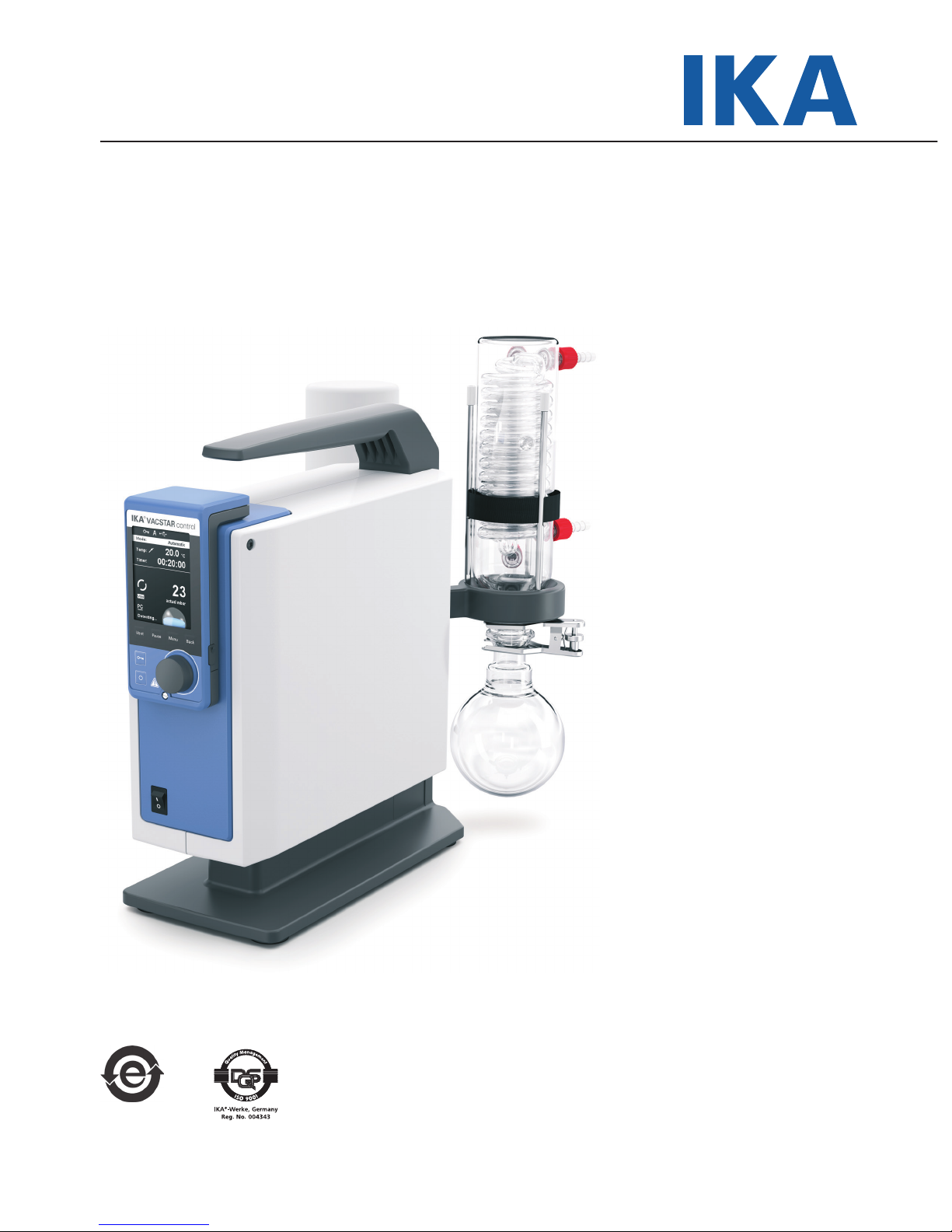
IKA Vacstar control
IKA Vacstar control_102018
Operating instructions EN
Page 2
2
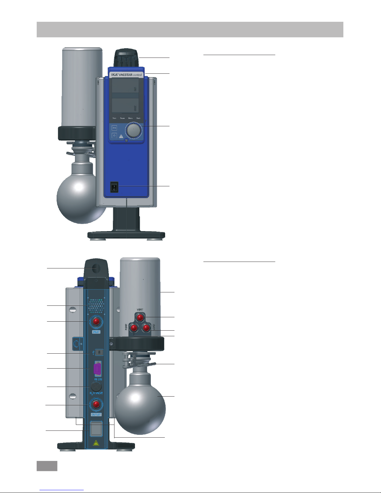
Device setup
Fig. 2
5
6
7
8
9
10
11
16
13
Pos. Description
1 Handle
2 WiCo (see chapter "Operator panel and display")
3 Rotating/pressing knob
4 Main switch (on/off)
Fig. 1
Pos. Description
5 Handle securing screw
6 Fan/Ventilation slit
7 Hose connection for suction line d= 8 mm (INLET)
8 USB interface
9 RS 232 interface
10 Water Valve Connection
11 Hose connection for pressure line d= 8 mm (OUTLET)
12 Mains cable connection
13 Pressure Device
14 Hose connection for ventilation line d= 8mm
15 Hose connection for load line d= 8mm
16 Hose connection for suction line d= 8 mm (INLET)
17 Clamp
18 Receiving flask
1
2
3
4
14
12
15
17
18
6
Page 3
3
Source language: German
Page
Device setup................................................................................................................................................................................ 2
EU Declaration of conformity ..................................................................................................................................................... 3
Explanation of warning symbols ................................................................................................................................................. 3
Warranty ................................................................................................................................................................................... 3
Safety instructions ...................................................................................................................................................................... 4
Unpacking ................................................................................................................................................................................. 6
Intended use ................................................................................................................................................................................ 7
Useful information ..................................................................................................................................................................... 7
Assembly and setting up............................................................................................................................................................... 9
Wireless controller (WiCo) .......................................................................................................................................................... 11
Operator panel and display ....................................................................................................................................................... 11
Commissioning .......................................................................................................................................................................... 12
Interfaces and outputs ............................................................................................................................................................... 20
Maintenance and cleaning ......................................................................................................................................................... 21
Error codes ................................................................................................................................................................................ 22
Accessories ................................................................................................................................................................................ 22
Product contact parts ................................................................................................................................................................. 22
Technical data ............................................................................................................................................................................ 23
Contents
We declare under our sole responsibility that this product corresponds to the directives 2006/42/EC, 2014/35/EU, 2014/30/EU and
2011/65/EU and conforms with the following standards or normative documents: EN 61010-1, EN 61326-1, EN 60529 and EN ISO 12100.
A copy of the complete EU Declaration of Conformity can be requested at sales@ika.com.
Bluetooth
®
module:
Directive: 2014/53/EU Standards: EN 60950-1, EN 300328, EN 301489-1, EN 301489-17
EU Declaration of conformity
Explanation of warning symbols
According to IKA‘s Terms and Conditions of sale and delivery, this
product is covered by a warranty for a period of 24 months. Please
contact your dealer for any warranty claims. If you wish, you can
send the device
directly to
our factory. Please provide
the sales
invoice and state the reasons for your guarantee claim. In this
case, you are responsible for shipping and handling costs.
Warranty
The warranty does not cover wearing parts, or defects that are the
result of improper use, insucient care and maintenance or failure
to follow the instructions in this operating manual.
EN
DANGER
WARNING
NOTE
CAUTION
Indicates an (extremely) hazardous situation, which, if not avoided, will result in death, serious injury.
Indicates a potentially hazardous situation, which, if not avoided, can result in death, serious injury.
Indicates a potentially hazardous situation, which, if not avoided, can result in injury.
Indicates practices which, if not avoided, can result in equipment damage.
Page 4
4
Safety instructions
General information
DANGER
Always wear personal protective
equipment in accordance with the
hazard class of the media being
worked with - otherwise there are
dangers due to spraying liquids, and
release of toxic or flammable gases.
NOTE
Please read the instruction manual
in full before use and follow the
safety instructions.
• Keep the
instruction
manual in a
place where
it can be
accessed easily.
• Ensure that only trained staff use the device.
• Follow the safety instructions, guidelines, occupational health
and safety and accident prevention regulations.
• The device and all parts of the device must not be used on
people or animals.
• Do not expose human or human body parts to vacuum.
For protection of the equipment
WARNING
Ensure that the substances used
with the device are compatible
with the materials of the device
parts that come into contact with
the product; see the chapter “Product contact parts”.
Work with the device
DANGER
You can
prevent
the
release
of
solvent vapours
into the atmosphere
using a
the downstream emis-
sion condenser VSE1.
WARNING
Inhaling or coming into contact
with media
such as poisonous
liquids, gases, spray mists,
vapours,
dusts or biological materials can
endanger the health of the user.
Ensure that all connections are
well sealed and free of leaks if you
are working with such media.
• The vacuum pump IKA Vacstar control must only be operated
under the conditions described in the chapter “Technical data”.
• Prevent release of the materials. Take measures to protect
staff and the environment.
• Pay attention to possible interactions or chemical or physical
reactions when working with media at reduced pressure and
increased temperature.
• There can be electrostatic processes between the medium
and the device which can lead to direct danger.
• Some medium may be released due to the residual leakage
rate of the device.
• Before commissioning check that all the housing parts are
present and fastened to the device.
• Do not lift the pump if the handle is loose and the handle
securing screw (Fig. 2, 5) is loose or missing!
• Only switch ON the pump if the pump is standing vertically.
• Connect the hose connections (INLET-OUTLET) and interfaces
in
accordance
with the
labelling
on the
device
and the
operating instructions.
• Ensure that the temperature of the evacuated medium is below its ignition temperature. The pumping process (compression) increases the temperature of the medium additionally.
• Ensure that vapours containing solvent cannot be sucked into
the pump.
• Prevent occurence of explosive mixtures; if appropriate connect inert gas for ventilation and/or thinning.
• Do not use the pump to create pressure.
• Observe the permitted pressure at the inlet and outlet side;
see the chapter “Technical data”.
• The gas flow must only be regulated/throttled in the suction-side line.
• When using the emission condenser VSE1 ensure that the
coolant is flowing freely.
CAUTION
The specified settings
on the
rating
plate must coincide with the actual
mains supply.
• The device is only disconnected from the mains supply when
the power or device plug is removed.
• The socket for the power cord set must be easy to access.
Device setup
DANGER
Do not use the device in explosive
atmospheres, it is not EX-protected.
In order to avoid injury to persons
and damage to property, observe
the relevant protective and accident prevention measures when
processing hazardous substances.
• Set up the device in accordance with the chapter “Setting up”
and connect the connection lines and interfaces as described.
• Set up the device control in a spacious area on an even, stable, clean, non-slip, dry and fireproof surface.
• Never work with a faulty or incorrectly connected device.
• Connect the vacuum pump to an exhaust line. Ensure that
the exhaust line cannot be kinked! The maximum permitted
length for the exhaust line is 2 metres.
• Prevent occurence of explosive mixtures; if appropriate connect inert gas for ventilation and/or thinning.
Page 5
5
Accessories
• Safe
operation
can only be
ensured
when working with
accessories as described in the “Accessories” section.
• Carefully observe the operating instructions for additional devices (e.g. rotary evaporators), with which the vacuum pump
IKA Vacstar control is operated.
• The pressure at the gas inlet and outlet must not exceed
1100 mbar.
WiCo
DANGER
Please note the following safety instructions for the battery pack RB 1
(rechargeable battery).
CAUTION
If during operation the battery pack
RB 1 (rechargeable battery) becomes
fully discharged, the device will contin
ue to run or is shut down depending
on the value settings for exceeding the
time. If the device is set so that it con
tinues to run when the battery of the
Wireless Controller (WiCo) is fully dis
charged, the only means of switching
the station off are the "safe STOP" and
the off switch!
• Keep the battery pack out of reach of children at all times.
• Store the battery pack in a cool, dry place.
• Never throw the battery pack into a fire. Keep it away from di
-
rect sunlight and temperatures above 60 °C. High temperatures
will damage the battery pack and render it unusable. Tempera
-
tures above 100 °C may cause it to explode.
• Never throw the battery pack into water or expose it to moisture. Water may lead to a short-circuit, causing the battery
pack to explode.
Disposal instructions
• When disposing of the IKA battery pack, please tape over the
contacts with adhesive tape to prevent short-circuiting due to
moisture or contact with metal components. Short-circuiting
may result in an explosion.
• Elastic hoes may be deformed under vacuum.
• Only use flexible hose lines.
• Observe your
emergency
measures for power failure and
ensure that the device is put in a safe mode (see the chapter:
Commissioning, Operating mode).
• Only use IKA approved accessories!
• Use only original IKA spare parts!
• Do not deform or crush the battery pack or damage it in any
other way. This can cause battery fluid to leak and/or the battery pack to explode.
• When not in use, keep battery packs away from paperclips,
coins, keys, nails, screws or other small metal objects which
could cause the contacts to be bridged. Short-circuiting may
result in an explosion.
• Explosion of a battery pack may release battery fluid and cause
a fire.
• The lithium polymer battery pack must only be used and charged
in IKA products designed for use with this battery pack.
• When the battery pack is inserted it should slide in easily and
without resistance. Do not force it.
• If the battery pack is removed for an extended period of time,
store it in a sealed plastic bag to prevent short-circuiting due to
moisture or contact with metal components.
• The operating temperature range of the battery pack is from
0 °C to +45 °C. Note that the battery pack capacity will be
reduced at temperatures below 20 °C.
• Only the rechargeable battery types recommended in the tech
nical data may be used in the device!Do not charge batteries
that have leaked or that are discolored, deformed or damaged
in any other way.
End users are obliged by law to return all used disposable and
rechargeable batteries. Throwing them into the house-hold
waste is prohibited! Disposable/rechargeable batteries contaiing harmful substances are marked with this symbol to indicate
that they may not be disposed of as household waste.
• The device, accessories, packaging and batteries must be di
posed of in accordance with local and national regulations.
• Covers or parts that can be removed from the device without
tools must later be refitted to ensure safe operation, unless
anything else is connected at this point. This will prevent the
infiltration of foreign objects, liquids and other contaminants.
• Unwanted
liquids that have
entered
can be
removed
by
extracting air during no-load operation.
• Avoid knocks or impact to the device.
• The device must only be opened by trained, skilled personnel
(who have been authorised to do so).
• The device must not be modified without authorisation from IKA.
• To ensure sufficient cooling for the vacuum pump IKA
Vacstar
control, the ventilation slits on the housing must not be covered.
• Only use original
replacement
parts for
maintenance
to
ensure that the device works reliably.
• Watch out for water
condensation
inside and outside the
device. Warm up the device first, if it has been brought in
from a cold environment.
• Never fasten the vaccum pump over a heating bath.
• Ensure that no solids and/or liquids can enter the diaphragm
of the vacuum pump IKA Vacstar control through the suction
line of the pump. This damages the diaphragm and other internal parts of the pump. This reduces flowrate and the final
pressure can no longer be achieved. Deposits may be produced in the interior, reducing service life and causing leaks.
Page 6
6
Unpacking
Unpacking
• Unpack the device carefully.
• Any damage should be notified immediately to the shipping
agent (post oce, railway network or transport company).
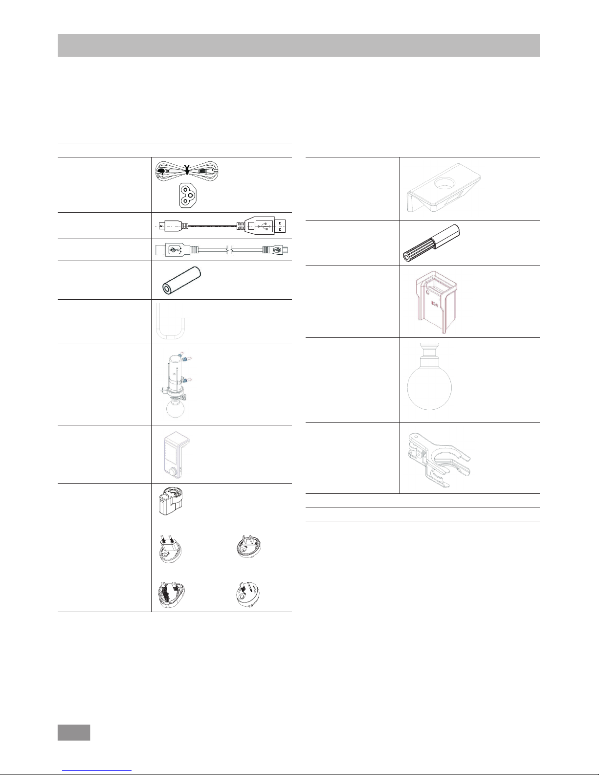
Scope of delivery
Diaphragm vacuum pump
IKA Vacstar
control
Power cord set
USB A - USB B cable
A
USB A - USB micro B
Vacuum hose 1 m
Vacuum Hose 0.3 m
(connection Vacstar to
Vacuum Safety VSE 1)
Vacuum Safety VSE 1
Wireless Controller
(WiCo)
OS 1.0 power supply unit
(for WiCo):
Adapter
UK
Adapter
USA, China
Adapter
Australia
Adapter
Europe, Switzerland
Cover
Screw driver
(screw driver to screw
WiCo on station)
Bracket
Flask
Spherical clamp
User guide
Warranty card
Page 7
7
Use
WARNING
The device must not be used for:
- evacuating biological habitats,
-
evacuating explosive, corrosive
or similar gases,
- throughput/use of liquids
The device is not suitable for:
- pumping up objects
- pumping liquids
- use in potentially explosive
atmospheres
- underwater
- underground
Set up
the IKA Vacstar control in a spacious area on an even, stable, clean,
non-slip, dry and fireproof surface.
Intended use
Useful information
DANGER
You can
prevent
the
release of
solvent vapours
into
the
atmosphere
using
a VSE 1.
WARNING
If the pump (station) generates vibration, the Wireless Controller
must be bolted to the pump using
the screw (p. 11), or positioned remotely from the stirrer (station)
whilst it is running.
CAUTION
Special care must be taken when
working with gas mixtures that include condensable gases (e.g. solvents). If diaphragm pumps are
used with such gases they condense
in the pump’s air flow. This leads to
a build-up of pressure in the vacuum chamber, which in turn influences the effectiveness and service life
of the diaphragms and valves.
CAUTION
If liquid or condensate enters the
vacuum chambers, the specified
minimum working pressure is no
longer achieved.
To
protect
the inner valves and
diaphragms against liquid, use an
upstream condensate separator,
such as a Woulff bottle.
It is generally recommended that
you run the pump with no load at
the end of the
process
(no-load
operation, approx. 3 up to max. 5
minutes) to dispel any residues in
the pump.
If applicable, vent the recipient.
To do this, remove the suction line
during manual operation.
NOTE
Observe the operating instructions
of the relevant devices.
Area of use (indoor use only)
- Laboratories - Schools
- Pharmacies - Universities
The device is suitable for use in all areas (EMC class A and B).
The laboratory diaphragm vacuum pump IKA
Vacstar
Control used
together with other laboratory devices to create and maintain vacuum. Vacuum controller and vacuum sensor is part of the device.
Along with the accessories recommended by IKA, the vacuum
pump IKA Vacstar control is suitable for controlled evacuation to a
specified final pressure e.g. for operating an IKA rotary evaporator.
It can also be used for classical separation, filtration or drying in
the laboratory.
With the integrated vacuum controller, the IKA Vacstar control can
operate automatically, for boiling point detection, scheduled pressure-time curves or programs from the solvent library.
Intended use: Tabletop device
Wireless remote control
Before using the wireless link between the Wireless Controller
(WiCo) and the laboratory device, first check whether your region
is included in the radio communications approval for the device.
If it is not, WiCo must remain on the station.
The safety of the user cannot be ensured:
• if modifications are made to the device or parts of the device
by third parties!
• if the device is operated in contravention of the safety instructions!
Page 8
8
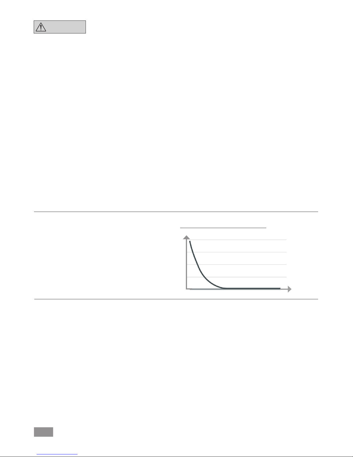
Analogue speed control
With this control, the speed of the pump, and therefore its suction power, is reduced the closer the measured pressure reaches
the target value. Once the target value is reached, the pump only
operates according to the leakage rate of the system. This enables
quiet functioning, precise vacuum control and a long service life
for the moving pump parts. Exact automatic boiling point recognition is possible with this type of control, meaning that the system
reaches and keeps the solvent at its boiling point in automatic
mode.
t
mbar
must be used, for example. Diaphragm vacuum pumps are often
used as pumps for the preliminary stage in these contexts.
Compressing and releasing the pressure on air creates a noise. The
pump is quieter the less air is transported. This means that there is less
operating noise during normal operation if the pressure is reduced.
The IKA
Vacstar
control is controlled via a Wireless Controller
(WiCo). If the WiCo is attached to the station, data exchange between the pump (station) and WiCo is performed via the contacts
(page 11, (A/Q)) "Home" symbol appears on the display of the
WiCo. If the WiCo is neither bolted to the station the data exchange between the pump and WiCo is performed via Bluetooth®.
In this case the Bluetooth® symbol is displayed. Depending on the
structure of the building, the WiCo can be operated at a distance
of up to 150 m from the station, using the Bluetooth® connection.
The WiCo can be attached to the pump (station), or can be installed in a safe place easily accessible by the user while the pump
is running. If the WiCo is attached to the station, the rechargeable
battery is automatically recharged via the contacts (page 11, (A/Q))
The rechargeable battery can also be charged via the USB port of
the WiCo.
In automatic operation with controlled speed the pump reduces its
speed when it reaches the target value. If the leakage rate in the
entire system is low enough, the speed may even be set to “zero”.
Schematic view of speed vacuum control
NOTE
Generally speaking, the smaller the
volume to be evacuated, the lower
the speed should be. The final pressure is not controlled.
Diaphragm vacuum pumps are oscillating displacement pumps.
The diaphragms expand the volume of the vacuum chamber to
produce an underpressure, which sucks air into the chamber. The
air is then pressed out of the vacuum chamber by subsequent
compression. Changes between the inlet and outlet are controlled
by diaphragm valves.
The physical unit for pressure is 1 Pascal [Pa].
However people often still use the unit millibar [mbar] colloquially.
1 mbar = 100 Pa
1 bar = 10
5
Pa
1 Pa = 10
-5
bar
1 Pa = 0.01 mbar
A distinction is made between different ranges in vacuum tech-
nology.
Rough vacuum: 10
5
to 10² Pa (1000 to 1 mbar)
Fine vacuum: 10² to 10
-1
Pa (1 to 10-3 mbar)
High vacuum: 10-1 to 10-5 Pa (10-3 to 10
-7
mbar)
Ultra high vacuum < 10-5 Pa (< 10
-7
mbar)
The periodic movements of the diaphragms create a vacuum at
the pump inlet. Diaphragm vacuum pumps work with a rough
vacuum of up to 10
2
Pa. Lower pressures cannot be achieved with
these pumps.
To create fine, high and ultra high vacuums, oil-sealed vacuum
pumps, screw pumps, diffusion pumps or turbomolecular pumps
Charging the RB 1 battery pack (rechargeable battery)
The battery pack of the Wireless Controller can be charged by any
of the following means:
• on the Vacstar station
• via a USB cable at the PC or station
• via an OS 1.0 power supply unit.
Page 9

9
Assembly and setting up
NOTE
Ensure that you follow the general
rule, that the recipient (load/vacuum container/glass condenser)
should always be connected to the
suction line at its highest point.
This reduces the risk of liquids entering the vacuum pump.
Liquid in the pump chambers makes
the pump properties worse.
Connect the hose connections (INLET/OUTLET) and interfaces in accordance with the labelling on the
pump and the operating instructions.
The connections are barbed hose connectors. Ensure that the hoses have hose clips if applicable.
Lay the hoses in such a way that no condensate can flow into the
pump.
Ensure that the air can enter the ventilation slit (Fig. 2, 6) unhindered.
Install a condensate separator (e.g. a VSW 1 in the suction line
before the intake spigot of the pump to protect against water
coming in.
If solvent vapours are sucked in, the emission condenser after the
pump helps to condense it, and prevents it being released into the
atmosphere.
Fig. 4
Fig. 5
Fig. 3
Water in
Water out
Page 10

10
conjunction with other devices with
labworldsoft® laboratory
device software. For further information see the chapter “
Interfaces
and outputs”.
Fig. 2, 10: Water valve connection
Connect the
optional
water
throttle
valve
(VSW1)
to the
dia-
phragm vacuum pump.
The water
flow
to the
emission
condensor is controlled using the water valve. The valve is opened as
soon as the pump is switched on.
Fig. 2, 11: Hose connection for suction line d= 8 mm OUTLET
Connect the suction line to this connection.
Link this connection to the recipient (rotary evaporator condenser,
laboratory reacor etc.) with a vacuum hose.
Fig. 2, 12: Power cord set connection
Check that the voltage information on the rating plate matches
your mains supply. Connect the power cord set to supply electricity.
Connection of interfaces
Fig. 2, 11: Hose connection d= 8 mm OUTLET
Link this connection to the emission condenser with a vacuum
hose, or fit a sound absorber to the end.
NOTE
Put the end of the hose in the fume
hood!
Check there is a free outlet on the
pressurised side!
Do not use a throttle on the pressurised side and do not close the
outlet! Connect the exhaust line to
this connection.
Fig. 2, 8: USB interface
Connect the vacuum pump IKA
Vacstar
control to a PC with a USB
A - USB B cable. Any device software updates can be loaded using
the IKA FUT software tool.
Fig. 2, 9: RS 232 interface
You can connect the IKA
Vacstar
control vacuum pump to a PC
using an RS 232 interface cable. The pump can be operated in
OUT
IN
cooling IN
cooling OUT
2
115/230 VAC
115/230 VAC
vacuum:
signal / power:
1
cooling
1 Recipient (load, e.g. rotary evaporator, reactor)
2 Vacuum separator (e.g. Woulff bottle)
Configuration
NOTE
Observe the operating instructions
for the devices.
When the target value is reached, the speed of the pump is
automatically reduced to a minimum of “0 rpm”. If the target
value has been reached, the pump sucks according to the leakage
rate of the vacuum system. Automatic boiling point detection is
possible.
Page 11

11
Wireless controller (WiCo)
Operator panel and display
Pos. Name
A PCB Contact Station PCB contact for WiCo
B Bluetooth
®
LED
Communication light
C PCB light Communication light
D Bluetooth
®
Recall key
WiCo connection
E Safe Stop Stop any function when WiCo is
unavailable
F Screw point WiCo to station securing position
G Displays Display the values and settings
H "Menu" key Press it once: main menu is displayed
Press it a second time: back to the
working screen
I "Back" key Return to the previous menu level
J USB interface Charging WiCo and connection to
computer
K Rotating/
pressing knob
Navigation, selecting and changing the
settings in the menu
L
Securing
screw
Secure the Wico to the station
M On/Off key Switching the Wireless Controller on and
off
N Lock key Key disable and rotary/push knob disable
O "Vent" key To vent the load if necessary during the
vacuum process
P "Pause" key Temporarily stop the function of the
device for required period.
Note: can resume the function by
pressing the button again
Q PCB Contact WiCo contact PCB to station
Changing the RB 1 battery pack in the WiCo
DANGER
Please comply with the relevant
safety instructions in the "Safety
instructions" section for the RB 1
battery pack!
Securing the WiCo to the stirrer
Attach the Wireless Controller (WiCo) to the charging contact provided on the station, and bolt it to the Vacstar station with the
screw.
Vacstar control Station
B
A
F
E
D
C
WiCo
N
M
L
K
J
I
H
G
O
Q
P
Page 12

12
NOTE
Observe the operating instructions
for the devices.
Check if the voltage specified on the type plate matches the available mains voltage. If these conditions are met, the device is ready
for operation when it is plugged in to the mains.
The socket used must be earthed
(grounded contact).
Otherwise safe operation is not guaranteed or the device may be
damaged.
Observe the ambient conditions indicated under “Technical data”.
Commissioning
Switching on
After switching off via the main switch (Fig. 1, (4)), the device type,
device designation, user-defined device name and the firmware
version are shown in the display.
Firmware Update Tool
After the start screen, the information start screen for the Firmware Update Tool appears. You can use the tool to update the software of your IKA device to the latest version. Firmware updates
contain new functions or optimisations of previous functions. You
can download the Firmware Update Tool at www.ika.de/fut.
Working screen (factory settings)
The following working screen appears automatically in the display.
Explanation of symbols on the working screen
Lock key:
This symbol means that the function of the key and of the rotary
knob for controlling the vacuum controller are disabled. The symbol no longer appears if the functions are enabled once again by
pressing the lock key a second time (min. 1 sec.).
Bluetooth®:
This symbol means the station and the WiCo are communicating
via Bluetooth
®
. The symbol no longer appears if no Bluetooth
®
communication is being performed.
B Operating mode:
The operating mode currently selected (A, B, C, D).
USB:
The vacuum controller is communicating via a USB cable. The symbol no longer appears if no USB cable is being used for communicating with the station.
Timer:
Appears when the timer display is active in the display.
PC:
The vacuum controller is connected to a computer and the device
is being controlled from the computer.
Page 13

13
PR:
The device is being controlled from the selected program.
Running mode:
The vacuum pump is running in a measurement
Vent:
The venting is enabled.
Vacuum:
The current pressure is less than the existing atmospheric pressure.
Detection:
This symbol is displayed during the automatic boiling point search,
the system pressure is reduced further.
Navigation menu and menu structure:
Navigation menu:
Press "Menu" key (H).
Select the menu by turning the rotating/pressing knob (K) to the right or left to select the desired menu
or sub-menu, which can then be selected by pressing the rotating/pressing knob (K).
Press or turn the rotating/pressing knob (K) again to select the desired menu option and edit the values
or settings, or activate/deactivate a function.
Turn the rotating/pressing knob to "OK" and press the "Back" (I) or "Menu" key (H) to end the procedure
and return to the previous menu or working screen.
Note: The menu option activated is highlighted blue in the display. Menus which are grayed out are inactive.
Navigation menu: Press the “Menu“ key (H) and turn the rotary/push knob (K)
Press the "Back" key (I) or the "Menu" key (H)
Note: If you press the “Menu“ key (H), the system skips directly back to the working screen.
If you press the “Back“ key (I), the system skips back to the previous display.
Back Back Back
Menu
Menu
Boiling:
This symbol indicates that a boiling point has been found automatically, the system pressure is kept constant.
Home:
The Wireless Controller is connected to the station and is communicating with the station via the charging contacts. The symbol no
longer appears if the WiCo is removed from the station.
Battery pack (rechargeable battery):
The charging status of the RB 1 battery pack within the WiCo. The
charging symbol appears if the WiCo
• is connected to a PC via a USB cable
• is connected to the power supply unit OS 1.0 via a USB cable
• is connected to the station via the charger contacts.
K
I
H
Page 14

14
Menu structure:
Factory settings
Menu
Pump
Limits
Cleaning
Deutsch
...
Display Timer
B
C
Operating Mode A
Display
Timer
Timer functions
Programs Program 01
....
Settings Languages English
Units
Temperature ºC
ºF
Safety
Modes
Automatic
Manual
Pump %
Program
Start after
Duration
Pump speed
Clean now
Actions after stop
Open water valve
Open vacuum valve
Cleaning
Maximum
Minimum
Manual
Maximum
Minimum
Pump %
Solvent library
Acetonitril
N-Amylalkohol
....
Time
Beep after stop
Activate
D
Program 10
Select
Edit
Delete
Edit/Insert/Delete
Last measurement
Select
Edit
Delete
Edit/Insert/Delete
Service Valves
Venting valve
Close/Open
Water valve
Close/Open
mbarPressure
torr
mmHg
hPa
Factory update info
Communication
Brightness
Pressure max.
Operating mode
Logic version
Volume
Pressure min.
Pump % max.
Pump % min.
Key tone
Device name
Firmware Update Info
Display version
Activated
Deactivated
20 %
05:00 [mm:ss]
Add solvente (No.1 ~ 5)
Pump
Display
Black/White
Background
Standard Mode
Battery Mode
Sound
Factory setting
Menu values
Programs
All
Bluetooth
®
Remote control
Paring
Information
Deactivated
Deactivated
-
06:00 [mm:ss]
00:00:01 [hh:mm:ss]
2 mbar
1100 mbar
100 %
0 %
-
-
-
-
Activated
Activated
Deactivated
Deactivated
Deactivated
Deactivated
Deactivated
Deactivated
Deactivated
Activated
Deactivated
Open
00:30
-
-
-
-
-
-
-
-
Deactivated
Open
Activated
Deactivated
Deactivated
Activated
Deactivated
Deactivated
Deactivated
-
Activated
B
Vacstar control
100 %
Black
80 %
Activated
10 %
Activated
-
-
-
Activated
Activated
Activated
-
-
-
1100 mbar
2 mbar
100 %
0 %
Safe pressure
Safe pump rate
Time
Password
1100 mbar
000
20 %
Page 15

15
Menu details
Pump
1. Press the "Menu" key (N).
2. Select the menu "Pump" and confirm the input.
3. Select the following settings:
- Modes
- Cleaning
- Limits
- Solvent library
- Actions after stop
Modes
Automatic:
In the “Modes” menu, you can enable automatic boiling point recognition by selecting the “Automatic” menu item. No other parameters
must be set. The boiling point is detected automatically. For rotary
evaporators with heating bath, it must be ensured that the tempering
medium and solvents have a constant temperature (e.g. 60 °C).
Manual
In the “Manual” menu item, the target value can be specified (e.g.
in "mbar”). The system is evacuated until the target value.
Pump %
By selecting the “Pump %” menu item, the pump can be operated
continuously
with a running performance of between 100 % and 1 %.
Program
Under the “Program” menu, 10 user-defined pressure-time profiles
can be created. The last measurement which is in manual mode can
be saved as a program. The target value and the running performance can only be entered within the set limits (see menu item “Limits”) switching to the working screen and pressing the rotary/push
knob starts the process. Pressing the knob again stops the process.
Cleaning
NOTE
The “Cleaning” menu item increases
the service life of the pump, since
solvent residues do not remain inside the pump.
The cleaning of the pump ensures that solvent residues are removed in the pump after the measurement. For this purpose, the
pump should run at a low speed rate while the system is venting.
The air flowing through the pump ensures that the solvent residues are discharged from the pump. If the cleaning option is
selected, the cleaning process will start after the measurement has
finished (see “Actions after stop”).
You can also clean the pump without using the corresponding menu
item. To do this, remove the hoses and operate the pump at the end
of a working cycle (test, test series, end of the day ...) at idling speed.
Start after…
Start a cleaning process after a measurement was running for at
least a interval. The default time is 5 minutes. This means that a
measurement must be run for at least 5 minutes, so that cleaning
is performed at the end of the measurement.
Duration
Specifies how long the cleaning process should be performed.
Pump speed
Determines at what power (in %) the pump is operated during
cleaning. If the power is set too high this can lead to a pressure drop
in the system.
Clean now
If you want to perform a cleaning, you can select it with this setting.
Page 16

16
Timer
1. Press the "Menu" key (N).
2. Select the menu "Timer" and confirm the input.
3. Select the following settings:
- Timer functions
- Display
Timer functions
NOTE
Timer function is disabled in auto
and program mode
You can stop the evacuation procedure before expiry of the set time.
In this case the countdown of the
timer is interrupted.
In the ”Timer” menu you can specify that the timer is displayed
on the display/working screen. A tick () shows that the option
is activated. This setting specify the actual time for the evacuation
procedure.
A default time can also be set for the timer. This setting start evacuation for a standard time. The device can emit a signal (beep)
after the set target time has elapsed.
Operating mode
1. Press the "Menu" key (N).
2. Select the menu "Operating mode" and confirm the input.
3. Select the following settings.
Operating mode A
In this operating mode, the set target value is not saved when the
current run comes to an end or the device is switched off.
Limits
In this menu, limits for the target value can be set.
Solvent Library
In the “solvent library”, the most common solvents are assigned a
function to determine the steam temperature at the set pressure
and vice versa. This provides assistance when setting these parameters in manual mode, for example, evaporation processes with
a rotary evaporator.
Actions after stop
Here you can define actions that should be performed when a test
has ended.
Page 17

17
Display
1. Press the "Menu" key (N).
2. Select the menu "Display" and confirm the input.
3. Select the following settings:
- Timer
In the “Display“ menu you can specify what information will be
displayed on the main screen.
Programs
1. Press the "Menu" key (N).
2. Select the menu "Programs" and confirm the input.
Select
To select a program, use the rotary/push knob and press “Select”.
Only a program which has the right parameters can be selected.
When a program has been successfully selected, this is indicated by a tick mark (). The vacuum controller is then in program
mode. In the main screen, the program view can then be selected
by turning the knob to the right. Turning the knob to the left returns to the main screen.
Start
To start a selected program, the push knob must be pressed in the
main screen.
Edit
Edit the selected program parameters. Start to edit the selected
program parameters by pressing on menu option "Edit" with rotary/push knob. You can edit, delete or insert one selected program
segment in the program.
Delete
Deletes the selected program. If a selected program is deleted by
pressing on menu option "Delete" with rotary/push knob, all the
program parameters will be emptied. The tick () disappears.
Details for editing the program
In this program, you can define up to 10 segments. The selected
segment is highlighted. Then, you can edit, delete or insert a segment in this program. The program is save automatically.
Edit
If the background of a selected value is yellow, you can change the
setting of the pressure value or the time value.
Delete
When a highlighted segment is deleted, the subsequent segments
move upward, closing the gap created by the deleted segment.
Operating mode B
In this operating mode, the set target value is saved when the
current run comes to an end or the device is switched off, and the
value can be changed.
Operating mode C
In this operating mode, the set target value is saved when the
current run comes to an end or the device is switched off and the
value cannot be changed.
Operating mode D
In this operating mode, the set pressure value will be set with a
short display and is saved when the current run ends or the device
is switched off.
Page 18

18
When a program is being edited, following screen appears. Sample for editing the program
Safety
1. Press the "Menu" key (N).
2. Select the menu "Safety" and confirm the input.
In the “Password“ menu, you can protect the WiCo settings using
a password. (factory setting: 000)
Time Out
In the “Time Out“ menu, you can set a time limit. This time limit
applies if there is a communication failure between the IKA Vacstar
and the WiCo or the communication range is exceeded. The IKA
Vacstar will continue to run at the set speed until the set time
has expired. After that the IKA Vacstar will continue to run at the
set safety pressure (manual mode) or safety pump rate( Pump %
mode) (see the "Safety" menu).
Edit pressure
Edit time
Example of saving the last measurement
Page 19

19
Service
1. Press the "Menu" key (N).
2. Select the menu "Service" and confirm the input.
In the “Service” menu, the valves and the pump can be operated
individually and also checked to ensure that they are operating
correctly.
Settings
1. Press the "Menu" key (N).
2. Select the menu "Settings" and confirm the input.
Languages
The “Languages“ option allows you to select the desired language
by turning and pressing the rotary/pressing knob (B). A tick ()
indicates the language that is set for the system.
Units
The “Units” option allows you to select the desired unit for displaying the pressure by turning and pressing the rotary/push knob. For
the pressure, the choice is “mbar”, “hPa”, “mmHg” or “Torr”. A
tick () indicates the unit that is set for the system.
Display
The ”Display“ option allows you to change the background color
and brightness of the working screen.
Sound
The ”Sound” option allows you to activate/deactivate the keypress sound and to set the volume.
Factory settings
You can choose this function if you want to reset the system parameters. There are three options to choose: "menu values", "programs" and "all". Select the option which is going to be reset.
Communication
The “Device name” option allows you to input a device name.
The device name appears on the opening screen when the device
is switched on. This can be useful when using multiple devices
with different set- tings. This also facilitates the identification of
each device when communicating with a PC via USB, RS232 and
Bluetooth
®
, for example.
Note: The coupling "Pairing" can only be performed if the wireless
controller is mounted on the station (see chapter "Device setup"
Fig. 1).
Information
The ”Information” option offers you an overview of the most important system settings of the IKA Vacstar Control.
NOTE
The initial setting for the time limit
is 30 seconds. You can set a value of
up to 60 minutes for this time limit.
Safe speed
In the "Safety" menu, you can specify a pressure or pump rate that is
appropriate and safe for the suction task. The safety pressure or safety pump rate applies if there is a communication failure between the
IKA Vacstar and the WiCo or the communication range is exceeded.
NOTE
The initial setting of the safety
pressure is 1100 mbar and or safety
pump rate is 20 %. it is implemented after expiry of the time limit
(see "Time out").
Page 20

20
Interfaces and outputs
NOTE
Please comply with the system requirements together with the operating instructions and help section included with the software.
The device can be operated in “Remote” mode via an RS232 or
USB interface using the laboratory software labworldsoft
®
. The RS
232 interface (M) at the back of the device is fitted with a 9-pole
SUB-D jack which can be connected to a PC. The pins are assigned
serial signals.
USB Interface
The Universal Serial Bus (USB) is a serial bus system which allows
the device to be connected to the PC. Devices that support USB
can be connected to each other whilst they are running (hot plugging) and provide automatic recognition of the connected devices
and their properties.
Use the USB interface in conjunction with labworldsoft® for operation in “Remote” mode and for updating the firmware using the
“Firmware update tool”.
Installation
Before the device is connected with the PC using the USB data
cable, the USB driver must be installed.
The USB driver can be downloaded from the website.
Serial interface RS 232 (V 24)
Configuration:
• The functions of the interface circuit between the dev ice
and the automation system are a selection from the signals
specified in the EIA standard RS232 as per DIN 66020 Part 1.
• Standard RS 232, corresponding to DIN 66259 Part 1 is valid
for the electric characteristics of the interface circuits and assignment of signal states.
• Transmission process: Asynchronous character transmission
in start-stop operation.
• Transmission type: Full duplex.
• Character format: Character composition according to data
format in DIN 66022 for start-stop operation. 1 start bit, 7
character bits, 1 parity bit (even), 1 stop bit.
• Transmission speed: 9600 Bits/s.
• Data flow control: none
• Access method: Data transmission from the device to the
computer only occurs after a request from the computer.
Command syntax and format
The following points should be noted for the instruction set:
• Commands are generally sent from the computer (master) to
the device (slave).
• The device only responds to requests from the computer.
Even error messages are not send spontaneously from the
device to the computer (automation system).
• The commands are transmitted in captial letters.
• Commands and parameters, as well as consecutive parame-
ters, must be separated by at least one space (code: hex 0x20
).
• Each individual command (including parameters and data)
and all responses are completed with CRLF (code: hex 0x20
hex 0x0d hex 0x0A) and can have a maximum length of 50
characters.
• The dot is used for decimal separators in a floating-point val-
ue (code: hex 0x2E).
The details given above generally comply with the recommendations of NAMUR (NAMUR recommendations for the design of
electrical plug-in connectors for analogue and digital signals in
laboratory MSR devices. Rev. 1.1).
The NAMUR commands and the additional IKA specific commands
are only used as low-level commands for communication between the
device and the PC. With an appropriate terminal or communication
program, these commands can be transmitted directly to the device.
NAMUR commands Function
Command
Firmware
Version
Description
IN_PARA1 0.0.020 Return the actual values
OUT_PARA1 0.0.020 Set the set values for the pump
control
OUT_PARA2 0.0.020 Set the set values for Bluetooth
connection
OUT_STATUS 0.0.020 Send the actual device status
IN_STATUS 0.0.020 Reads the status of a device
IN_VERSION 0.0.020 Read the version of the firmware
IN_DATE 0.0.020 Read the release date of the display/
logic firmware
IN_NAME 0.0.020 Read the name of the device
IN_DEVICE 0.0.020 Read the device type.
IN_ADDRESS 0.0.020 Read mac address of Wico.
IN_PARING 0.0.020 Read paired mac address of station.
OUT_ADDRESS 0.0.020 Write new paired mac addresses of
both station and Wico.
IN_SP_66 0.0.020 Reads the set pressure value
OUT_SP_66 0.0.020 Sets set point pressure value
IN_PV_66 0.0.020 Reads the actual pressure value
IN_MODE_66 0.0.020 Reads the evacuating mode
OUT_
MODE_66
0.0.020 Sets the evacuating mode
IN_ERROR 0.0.020 Reads error state
OUT_ERROR 0.0.020 Test Error. Sends out error code
IN_BT_NAME 0.0.020 Reads Bluetooth Device Name
IN_CUSTOM_
DEVICE_NAME
0.0.020 Reads custom device name
OUT_CUSTOM_DEVICE_
NAME
0.0.020 Sets custom device name
IN_WD1@ 0.0.020 Reads communication watchdog
time
OUT_WD1@ 0.0.020 Sets communication watchdog time
OUT_WD2@ 0.0.020 Set PC communication watchdog
time 2
OUT_SP_41 n
(0 -100 %)
0.0.020 Set the PC safety pump rate
OUT_SP_42 0.0.020 Set the PC safety pressure
RESET 0.0.020 Switch to normal operating mode
START_66 0.0.020 Starts the measurement
STOP_66 0.0.020 Stops the measurement
ENTER_IAP 0.0.020 Starts IAP mode
CALIB_66 0.0.020 It is used to calibrate vacuum.
IN_CALIB_66 0.0.020 It is used to read vacuum calibration
values
OUT_CALIB_66 0.0.020 It is used to calibrate vacuum.
Page 21

21
Accessories: PC 1.1 cable (device to PC)
Required for connecting the 9-pin socket to a PC.
Fig. 10
USB A - USB B cable
Required for connecting the USB interface (L) to a PC.
USB B
USB A
A
Fig. 11
Maintenance and cleaning
The device is maintenance-free. However it is subject to natural
wear and tear on parts and their statistical failure rate.
Unplug from the mains before cleaning.
Only clean the IKA device using these IKA approved cleaning
agents:
Dirt Cleaning agent
Dyes Isopropyl alcohol
Building materials Water containing detergent, isopropanol
Cosmetics Water containing detergent, isopropanol
Food Water containing detergent
Fuels Water containing detergent
Other materials Please ask IKA
• Wear protective gloves when cleaning the devices.
• Do not place electrical appliances into the cleaning agents for
cleaning purposes.
• Ensure no liquid enters the device during cleaning.
• Please consult with IKA before using any cleaning or decontamination methods not specifically recommended.
Ordering spare parts
When ordering spare parts, please make sure to indicate the fol-
lowing:
• Device type
• Device manufacturing number; see rating plate
• Reference number and description of spare part; see spare
part diagram and list at www.ika.de.
Repairs
Please only send devices in for repair that have been
cleaned and are free of materials which might present
health hazards.
For this, use the “certificate of compliance” form which you
can obtain from IKA or can download a version for printing from
the IKA website www.ika.de
If your appliance requires repair, return it in its original packaging.
Storage packaging is not sucient. also use appropriate transport
packaging.
1
2 RxD
3 TxD
4
5 GND
6
7 RTS
8 CTS
9
1
RxD 2
TxD 3
4
GND 5
6
RTS 7
CTS 8
9
PC
1
2
3
4
5
6
7
8
9
9
8
7
6
5
4
3
2
1
“Watchdog” functions; monitoring of the serial data flow
If, once this function has been activated (see NAMUR commands),
there is no retransmission of the command from the computer
within the set time (“watchdog time”), the Evacuation function is
switched off in accordance with the set “watchdog” mode or is
returned to previously set target values. The data transmission may
be interrupted by, for example, a crash in the operating system,
a power failure in the PC or an issue with the connection cable
between the computer and the device.
“Watchdog” mode 1
If event WD1 should occur, the evacuation function is switched
off and WD1 Watchdog Error is displayed. Set watchdog time to
m (20- 1,500) seconds, with watchdog time echo. This command
launches the watchdog function and must be transmitted within
the set watchdog time.
“Watchdog” mode 2
If there is an interruption in data communications (longer than the
set watchdog time), the speed target value is changed to the set
WD safety speed limit. The warning PC 2 is displayed. The WD2
event can be reset with OUT_WD2@0 - this also stops the watchdog function.
Set watchdog time to m (20- 1,500) seconds, with watchdog time
echo. This command launches the watchdog function and must
be transmitted within the set watchdog time.
Page 22

22
Error codes
If an error occurs, this is shown in an error on the display (B), e.g. Error 4.
Proceed as follows:
• Switch the device off on the device switch,
• Take corrective measure,
• Switch device back on.
Error code Description Detection Reason Action
Error 3 Device temperature
error
The temperature of
device has exceeded the
limit.
The temperature is too high. Stop the device for a while and restart
again. If the problem occurs again and
again, please call service department.
Error 4 Motor overload Motor overload The motor is blocked be-
cause of overload.
Stop the device for a while and restart
again. If the problem occurs again and
again, please call service department.
Error 8 Speed sensor fault. Device can’t detect the
pump speed.
The sensor occurs some
unknown errors that device
can’t read the speed value.
Call service department.
Error 9 Storage Error Read or write internal
flash error.
Read or write internal flash
error.
Call service department.
In the event that the fault cannot be eliminated using the measures described or another error code is displayed:
• Please contact the Service Department,
• Send the device and a brief description of the fault.
Accessories
• Vacuum hose IKA VH.SI.8
• PC 1.1 cable (RS 232)
• Woulff bottle/water valve set VSW1
For further accessories see www.ika.de
Product contact parts
Name Material
Connection spigot PPS
Connection piece PPS
Distributor PPS
Head piece PPS
Diaphragm valve/O-ring FFPM
Diaphragm NBR/PTFE
Clamp PPS
Connection piece PTFE
Pressure sensor AL203
Page 23

23
Technical data
Base unit Value
Pump rate max. [m³/h] 1.32
Pump rate max. [l/min] 22
Final pressure without gas ballast [mbar] 2
Suction levels [-] 4
Cylinder [-] 4
Connection diameter suction side [mm] 8
Connection diameter pressure side [mm] 8
Input pressure min. [mbar] 2
Input pressure max. [mbar] 1030
Boiling point detection [-] yes
Solvent library [-] yes
Analog speed vacuum control [-] yes
Speed control [-] Turning knob
Display [-] TFT
Pressure unit / scale [-] mbar, hPa, mmHg, Torr
Vacuum sensor [-] yes
Vacuum sensor type [-] ceramic Al2O3
Pressure max. for pressure sensor [bar] 1.2
Measurement range (absolute) min. [mbar] 1
Measurement range (absolute) max. [mbar] 1030
Resolution pressure [mbar] 1
Measurement uncertainty [mbar] 1
Venting valve [-] yes
Condensate trap [-] yes
Emission condenser [-] yes
Timer [-] yes
Noise at low. pressure [dB(A)] 54
Material in contact with medium [-] Al2O3, PTFE, FPM, PPS
Housing material [-] Alu-cast coating
Mode automatic [-] yes
Mode manual [-] yes
Mode pump % [-] yes
Mode program [-] yes
Width [mm] 270
Depth [mm] 500
Height [mm] 435
Weight [kg] 14
Permissible ambient temperature min. [°C] 5
Protection class II
Overvoltage category !
Degree of contamination 1
Use above max. MSL m 2000
Firmware update yes
Page 24

24
Base unit Value
Permissible ambient temperature max. [°C] 40
Permissible relative humidity [%] 80
Protection class according to DIN EN 60529 [-] IP 20
USB interface [-] yes
RS 232 interface [-] yes
Voltage [V] 100 - 240
Frequency [Hz] 50/60
Power input [W] 140
Power input standby [W] 1.5
Average values.
Subject to technical changes!
Page 25

25
Page 26

IKA - Werke GmbH & Co.KG
Janke & Kunkel-Str. 10
D-79219 Staufen
Tel. +49 7633 831-0
Fax +49 7633 831-98
sales@ika.de
www.ika.com
 Loading...