

Page 1
17 104 00
032011
Reg.-No. 4343-01
Betriebsanleitung DE 3
Operating instructions EN 7
Mode d’emploi FR 11
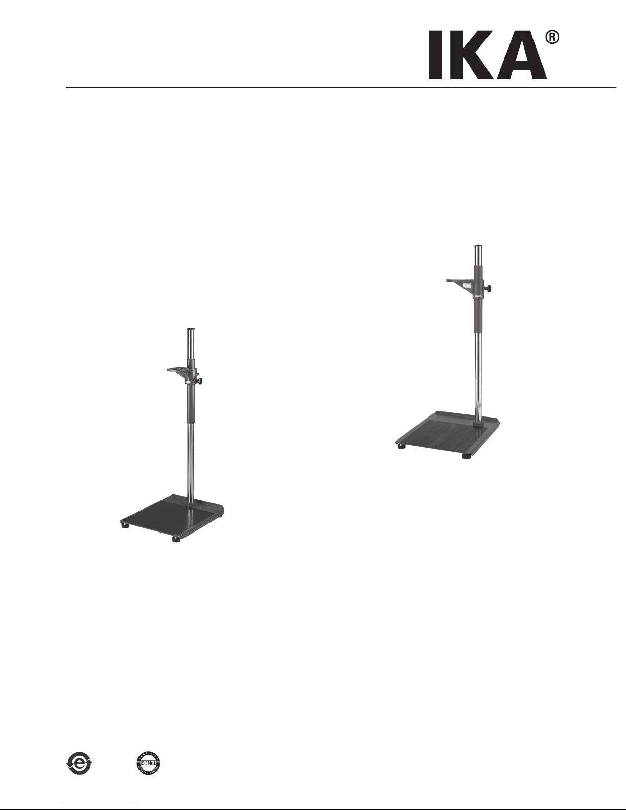
Teleskopstativ / Telescopic stand / Statif télescopique
R 474
T 653
Page 2

Page 3
3
Ursprungssprache
DE
Seite
Zeichenerklärung 3
Sicherheitshinweise 4
Auspacken 4
Bestimmungsgemäßer Gebrauch 5
Aufstellung und Inbetriebnahme 5
Wartung und Reinigung 6
Zubehör 6
Technische Daten 6
Gewährleistung 6
Inhaltsverzeichnis
Zeichenerklärung
Allgemeiner Gefahrenhinweis
Mit diesem Symbol sind Informationen gekennzeichnet, die für die Sicherheit Ihrer Gesundheit
von absoluter Bedeutung sind. Missachtung kann zur Gesundheitsbeeinträchtigung und Verletzung führen.
Mit diesem Symbol sind Informationen und Hinweise gekennzeichnet, die für den korrekten Umgang von Bedeutung sind.
Page 4
4
• Lesen Sie die Betriebsanleitung vor Inbetriebnahme vollständig und beachten Sie
die Sicherheitshinweise.
• Bewahren Sie die Betriebsanleitung für Alle zu-
gänglich auf.
• Beachten Sie, dass nur geschultes Personal mit
dem Gerät arbeitet.
• Beachten Sie die Sicherheitshinweise, Richtli-
nien, Arbeitsschutz -und Unfallverhütungsvorschriften.
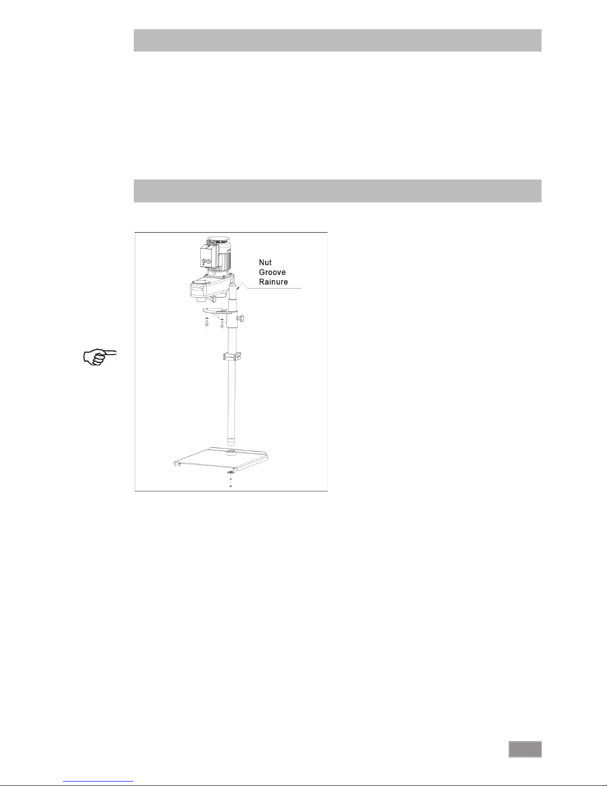
• Die Stativsäule muss so in die Fußplatte gesteckt
werden, dass die Führungsnut hinten ist. Andere Ausrichtungen sind nicht zulässig, da sonst
das Stativ mit aufgebautem Gerät kippen kann.
• Stellen Sie das Stativ frei auf einer ebenen, sta-
bilen, sauberen, rutschfesten, trockenen und
feuerfesten Fläche auf.
• Kleine Bodenunebenheiten, die zum Wackeln
führen, müssen mit den höhenverstellbaren Füßen ausgeglichen werden.
• Das Dispergiergerät T 65 D ULTRA-TURRAX®
muss mit einem Helfer auf den Führungskopf
des Teleskopstativs gehoben werden und ge-
mäß der Betriebsanleitung T 65 D ULTRA-TURRAX® mit den beiden mitgelieferten Schrauben
und Zahnscheiben befestigt werden. Das Gerät
muss nach vorne über der Fußplatte stehend
montiert werden, eine andere Ausrichtung
ist nicht zulässig, da sonst der Aufbau kippen
könnte.
• • Das Rührgerät IKA® RW 47 D muss mit einem
Helfer auf den Führungskopf des Teleskopstativs gehoben werden und gemäß der Betriebsanleitung IKA® RW 47 D mit den vier mitgelieferten Schrauben befestigt werden. Das Gerät
muss nach vorne über der Fußplatte stehend
montiert werden, eine andere Ausrichtung
ist nicht zulässig, da sonst der Aufbau kippen
könnte.
Sicherheitshinweise
• Für diese höhenverstellbaren Teleskopstative
muss eine Sicherheitsabschaltung angebracht
werden, die das Gerät stoppt, wenn das Stativ während des Betriebes nach oben verstellt
wird.
• Schalten Sie das Gerät aus bevor Sie das Teles-
kopstativ nach oben verstellen.
• Achten Sie beim Herunterfahren des Teleskopstativs, dass sich keine Körperteile zwischen
den Sicherheitsschaltern befi nden (Quetschgefahr).
• Schalten Sie das Gerät erst ein, wenn sich das
Werkzeug (Rührer bzw. Dispergierschaft) im
Behälter befi ndet.
• Durch Vibrationen kann sich die Griffschraube
am Stativ lösen, was zum Absenken des Ge-
rätes führen würde. Kontrollieren Sie deshalb
regelmäßig während des Betriebes den festen
Sitz der Griffschraube und ziehen Sie diese gegebenenfalls wieder fest.
• Heben bzw. senken Sie das Stativ nach dem
Lösen der Griffschraube, indem Sie die Hand-
kraft möglichst nahe an der Stativsäule anbrin-
gen. Je weiter die Kraft von der Säule entfernt
angebracht wird, desto mehr Kraft müssen Sie
aufbringen, außerdem wird die Kippgefahr er-
höht.
• Sichern Sie die Behälter gegen Verdrehen, in-
dem Sie beispielsweise einen Spannhalter verwenden.
• Beachten Sie die Betriebsanleitung des Dispergiergerätes T 65 D ULTRA-TURRAX® oder des
Rührgerätes IKA® RW 47 D!
• Prüfen Sie vor jeder Verwendung Gerät und
Zubehör auf Beschädigungen. Verwenden Sie
keine beschädigten Teile.
• Vermeiden Sie Stöße und Schläge auf Gerät
oder Zubehör.
• Auspacken
- Packen Sie das Gerät vorsichtig aus
- Nehmen Sie bei Beschädigungen sofort den
Tatbestand auf (Post, Bahn oder Spedition)
Auspacken
• Lieferumfang
Teleskopstativ
- Teleskopstativ entsprechend des bestellten
Typs T 653 oder R 474
- Betriebsanleitung
Aus versandtechnischen Gründen wird das Teleskopstativ in vormontierte Baugruppen zerlegt.
Page 5
5
Aufstellen des Statives
Die Stativsäule wird so in die Fußplatte gesteckt,
dass die Führungsnut in der Stativsäule hinten
ist. Die schwarze Griffschraube befindet sich
dann auf der rechten Seite. Mit Sechskantmutter,
Zahnscheibe und einer großen geprägten Scheibe wird die Stativsäule von unten festgeschraubt.
Alle vier Gummifüße sind in der Höhe verstellbar,
so dass ein wackelfreier Aufbau auch auf unebenen Boden möglich ist.
In der Fußplatte des Teleskopstatives R 474 ist
außerdem eine Bohrung zum Anschrauben eines
Stativstabes mit 16 mm Durchmesser vorgesehen. An diesem Stativstab kann ein Spannhalter
befestigt werden.
Aufstellung und Inbetriebnahme
Gerätemontage
Das Rührwerk IKA® RW47 D bzw. das Disper-
giergerät T 65 D ULTRA-TURRAX® wird auf den
Stativarm gesetzt und mit den mitgelieferten
Schrauben von unten angeschraubt. Zum Auf-
schrauben des Dispergiergeräts T 65 D ULTRATURRAX® ist ein Helfer erforderlich.
Die im Lieferumfang enthaltene Kabelschelle
wird zur Befestigung des Gerätenetzkabels benötigt.
Sicherheitsabschaltung
Die höhenverstellbaren Teleskopstative müssen
mit einer Sicherheitsabschaltung ausgerüstet
werden. Wir empfehlen die Montage des Sicherheitsendschalters SI400 zusammen mit der Halterung SI474. Hinweise zur Montage fi nden Sie
in den Betriebsanleitungen der Geräte.
Inbetriebnahme
Durch Öffnen der Griffschraube lässt sich das
Stativ anheben und absenken. Die eingebaute Gasfeder dient dazu, die dafür benötigte
Handkraft möglichst klein zu halten. Die Handkraft muss nahe an der Stativsäule angebracht
werden, damit das Anheben und Absenken mit
geringem Kraftaufwand möglich ist. Wird weit
von der Stativsäule entfernt die Kraft zum An-
heben oder Absenken angebracht, entsteht ein
Drehmoment und dadurch erhöhte Reibung an
der Säulenführung. Dies führt dazu, dass sich
das Stativ nur sehr schwer oder überhaupt nicht
bewegen lässt, außerdem erhöht sich die Kipp-
gefahr.
Befi ndet sich das Gerät in der richtigen Höhe,
wird die Griffschraube mit der Hand festgezo-
gen. Kontrollieren Sie während des Betriebes re-
gelmäßig den festen Sitz der Griffschraube und
ziehen Sie diese gegebenenfalls wieder fest.
Bestimmungsgemäßer Gebrauch
Der Schutz für den Benutzer ist nicht mehr gewährleistet, wenn das Gerät mit Zubehör betrieben wird, welches nicht vom Hersteller geliefert
oder empfohlen wird oder wenn das Gerät in
nicht bestimmungsgemäßem Gebrauch entgegen der Herstellervorgabe betrieben wird oder
wenn Veränderungen am Gerät durch Dritte vorgenommen werden.
Verwendungszweck
Das Teleskopstativ T 653 dient ausschließlich der
Befestigung von T 65 D ULTRA-TURRAX® Dispergiergeräten.
Das Teleskopstativ R 474 dient ausschließlich der
Befestigung von IKA® RW 47 D Rührgeräten.
Page 6

6
• SI 400 Sicherheitsendschalter
Entsprechend den IKA-Verkaufs- und Lieferbedin-
gungen beträgt die Gewährleistungzeit 24 Monate. Im Gewährleistungsfall wenden Sie sich
bitte an Ihren Fachhändler. Sie können aber auch
das Gerät unter Beifügung der Lieferrechnung
und Nennung der Reklamationsgründe direkt an
unser Werk senden. Frachtkosten gehen zu Ihren
Lasten.
Zubehör
Gewährleistung
Technische Daten
• SI 474 Halterung
Die Gewährleistung erstreckt sich nicht auf Verschleißteile und gilt nicht für Fehler, die auf unsachgemäße Handhabung und unzureichende
Pfl ege und Wartung, entgegen den Anweisun-
gen in dieser Betriebsanleitung, zurückzuführen
sind.
Durchmesser Stativstange mm 48
Abmessungen (BxHxT) mm 460 x 1200 x 530
Hub (Gasfeder) mm 500 - 1000
Technische Änderung vorbehalten!
Die Stativsäule muss immer leicht eingeölt sein,
damit das Heben und Senken nicht durch erhöhte
Reibung erschwert wird.
Ansonsten ist das Teleskopstativ wartungsfrei.
Ersatzteilbestellung
Bei Ersatzteilbestellungen geben Sie bitte Folgendes an:
- Gerätetyp
- Fabrikationsnummer des Gerätes, siehe Typenschild
- Positionsnummer und Bezeichnung des Er-
satzteiles, siehe Ersatzteilbild und -liste unter
www.ika.com.
Reparaturfall
Im Reparaturfall muss das Gerät gereinigt und frei
von gesundheitsgefährdenden Stoffen sein.
Senden Sie das Gerät in der Originalverpackung
zurück. Lagerverpackungen sind für den Rückver-
sand nicht ausreichend. Verwenden Sie zusätzlich
eine geeignete Transportverpackung.
Wartung und Reinigung
Reinigen Sie das IKA®Gerät nur mit diesen von
IKA® freigegebenen Reinigungsmitteln:
Verschmutzung Reinigungsmittel
Farbstoffe Isopropanol
Baustoffe Tensidhaltiges Wasser,
Isopropanol
Kosmetika Tensidhaltiges Wasser,
Isopropanol
Nahrungsmittel Tensidhaltiges Wasser
Brennstoffe Tensidhaltiges Wasser
Nicht genannte Stoffe Bitte fragen Sie
bei IKA® nach
- Tragen Sie zum Reinigen der Geräte Schutzhandschuhe.
- Falls andere als die empfohlenen Reinigungsoder Dekontaminationsmethoden angewendet werden, fragen Sie bitte bei IKA
®
nach.
Page 7

7
Source language: German
EN
Page
Explication of warning symbols 7
Safety instructions 8
Unpacking 8
Correct use 9
Set-up and Commissioning 9
Maintenance and cleaning 10
Accessories 10
Technical data 10
Warranty 10
Contents
Explication of warning symbols
General hazard
This symbol identifi es information that is of vital importance for safeguarding your health and
safety. Disregarding this information can lead to health impairment and injuries.
This symbol identifi es information and notes that are of importance for correct handling of the
unit.
Page 8

8
• Read the operating instructions in full
before starting up and follow the safety
instructions.
• Keep the operating instructions in a place whe-
re they can be accessed by everyone.
• Ensure that only trained staff work with the ap-
pliance.
• Follow the safety instructions, guidelines, occu-
pational health and safety and accident prevention regulations.
• The stand pillar must be inserted into the base-
plate so that the guide groove is at the back.
Other alignments are not permissible, as otherwise the stand can topple over when a unit is
mounted on it.
•
Set up the stand in a spacious area on an even,
stable, clean, non-slip, dry and fireproof surface
.
• Any small unevennesses that cause the stand to
rock must be compensated for with the height-
adjustable feet.
• The T 65 D ULTRA-TURRAX® dispersion unit
must be lifted on to the guide head of the telescopic stand with the aid of an assistant, and
secured with the two screws and toothed lock
washers (supplied), in accordance with the T 65
D ULTRA-TURRAX® operating instructions. The
unit must be mounted in front, vertically above the baseplate; a different alignment is not
permissible, as otherwise the assembly could
topple over.
• The overhead stirrer IKA® RW 47 D must be
lifted on to the guide head of the telescopic
stand with the aid of an assistant, and secured
with the four screws (supplied), in accordance
with the IKA® RW 47 D operating instructions.
The unit must be mounted in front, vertically
above the baseplate; a different alignment is
not permissible, as otherwise the assembly
could topple over.
Safety instructions
• This telescopic stand must be fitted with a sa-
fety disconnection device, which stops the unit
if the stand is moved upwards when the unit
is operating.
• Switch the unit off before moving the telesco-
pic stand upwards.
• When lowering the telescopic stand, take care
that no parts of the body get between the safety switches (danger of crushing).
• Only switch the unit on when the tool (agitator
or dispersion unit) is in the vessel.
• The handwheel bolt on the stand can come
loose due to vibration, which would lead to
the unit moving down. So, check the tightness
of the handwheel bolt regularly when using
the unit, and retighten it if necessary.
• Raise or lower the stand (after slackening the
handwheel bolt) by applying the manual force
as close as possible to the stand pillar. The
further the force is applied from the pillar, the
more force you need to apply, plus there is an
increased risk of the equipment toppling over.
• Secure the vessel against spinning round, by
using a clamp, for example.
• Beachten Sie die Betriebsanleitung des Dispergiergerätes T 65 D ULTRA-TURRAX® oder des
Rührgerätes IKA® RW 47 D!
• Check the appliance and accessories before-
hand for damage each time you use them. Do
not use damaged components.
• Protect the appliance and accessories from
bumps and impacts.
• Unpacking
- Please unpack the device carefully
- In the case of any damage a detailed report
must be set immediately (post, rail or forwarder)
Unpacking
• Delivery scope
Telescopic stand
- Telescopic stand corresponding to
the type ordered T 653 oder R 474
- Operating instructions
For technical reasons associated with shipping,
the telescopic stand is supplied stripped down,
as pre-assembled modules.
Page 9

9
Setting up the stand
The stand pillar is inserted into the baseplate so
that the guide groove is at the back. The black
handwheel bolt is then on the right. The stand
pillar is then secured from below with a hexagon
nut, toothed lock washer and a large shaped
washer.
All four rubber feet are height-adjustable, so the
stand can be set up so it does not rock, even on
uneven floors.
In addition, a hole is provided in the baseplate of
the R 474 telescopic stand, for screwing on a 16
mm diameter support rod. A clamp can be fi xed
on this rod.
Set-up and commissioning
Mounting the unit
The RW 47 D agitator unit or the T 65 D ULTRATURRAX® dispersion unit are placed on the arm
of the stand and bolted on from below with the
bolts supplied. The help of an assistant is needed
for screwing on the T 65 D ULTRA-TURRAX® di-
spersion unit.
The cable clips included in the delivery package
are required for fi xing the power cable of the
unit.
Safety disconnection device
The height-adjustable telescopic stand must be
fi tted with a safety disconnection device. We recommend installation of the SI400 safety limit
switch together with the SI474 clamp support.
You will fi nd information on their installation in
the operating instructions of the units.
Commissioning
The stand can be raised and lowered by loosening the handwheel bolt. The integral gas shock
absorber helps to keep the manual force needed
for this as light as possible. The manual force
must be applied close to the stand pillar, so that
the stand can be raised and lowered with only
a slight use of force. If the force for raising or
lowering is applied at a distance from the stand
pillar, a turning moment results, leading to increased friction on the pillar guide. As a result, the
stand can only be moved with great diffi culty, or
cannot be moved at all. Besides this, the danger
of the stand toppling over is increased.
When the unit is at the correct height, the handwheel bolt is tightened by hand. Check the tightness of the handwheel bolt regularly when using
the unit, and retighten it if necessary.
Correct use
The safety of the user cannot be guaranteed if
the appliance is operated with accessories that
are not supplied or recommended by the manufacturer or if the appliance is operated improperly contrary to the manufacturer’s specifi cations
or if the appliance is modifi ed by third parties.
Use
The T 653 telescopic stand is used solely for
mounting T 65 D ULTRA-TURRAX® dispersion
units.
The R 474 telescopic stand is used solely for
mounting IKA® RW 47 D agitator units.
Page 10

10
• SI 400
Safety limit switch
In accordance with IKA® warranty conditions,
the warranty period is 24 months. For claims under the warranty please contact your local dealer. You may also send the machine direct to our
works, enclosing the delivery invoice and giving
reasons for the claim. You will be liable for freight
costs.
Accessories
Warranty
Technical data
• SI 474
Support holder
The warranty does not cover wearing parts, nor
does it apply to faults resulting from improper
use or insuffi cient care and maintenance contrary to the instructions in this operating manual.
Diameter stativ rod mm 48
Dimensions (WxDxH) mm 460 x 1200 x 530
Lift (gas spring) mm 500 - 1000
Subject to technical changes!
The stand pillar must always be lightly oiled, so
that raising and lowering is not made more diffi cult due to increased friction.
Apart from this, the telescopic stand is maintenance-free.
Spare parts order
When ordering spare parts, please give:
- Machine type
- Manufacturing number, see type plate
- Item and designation of the spare part, see
www.ika.com, spare parts diagram and spare
parts list
Repair
In case of repair the device has to be cleaned and
free from any materials which may constitute a
health hazard.
If you require servicing, return the appliance in
its original packaging. Storage packaging is not
suffi cient. Please also use suitable transport pa-
ckaging.
Maintenance and Cleaning
Only clean IKA® appliances using these IKA®
approved cleaning agents:
Dirt Cleaning agent
Dyes Isopropanol
Building materials Water containing
detergent,
Isopropanol
Cosmetics Water containing
detergent,
Isopropanol
Food Water containing
detergent,
Fuels Water containing
detergent,
Other materials Please consult IKA
®
- Wear protective gloves when cleaning the de-
vices.
- Please consult IKA® before using any cleaning
or decontamination methods, other than those recommended here.
Page 11

11
Langue d'origine: allemand
FR
Page
Explication des symboles 11
Conseils de sécurité 12
Déballage 12
Utilisation conforme 13
Installation et mise en service 13
Entretien et nettoyage 14
Accessoires 14
Caractéristiques techniques 14
Garantie 14
Sommaire
Explication des symboles
Remarque générale sur un danger.
Le présent symbole signale des informations cruciales pour la sécurité de votre santé. Un non-
respect peut provoquer des problèmes de santé ou des blessures.
Ce symbole repère des informations et consignes importantes pour une bonne utilisation.
Page 12

12
• Lisez intégralement la notice d'utilisation
avant la mise en service et respectez les
consignes de sécurité.
• Laissez la notice à portée de tous.
• Attention, seul le personnel formé est autorisé
à utiliser l'appareil.
• Respectez les consignes de sécurité, les directi-
ves, ainsi que les prescriptions pour la prévention des accidents du travail.
• La colonne de statif doit être insérée dans le
socle de façon que la rainure de guidage se
trouve à l'arrière. Toute autre orientation est in-
terdite sous risque de voir le statif basculer une
fois l'appareil monté.
• Placez le statif en aire spacieuse sur une surface
plane, stable, propre, non glisssante, sèche et
inflammable.
• Les petites inégalités du sol entraînant
l'instabilité du statif doivent être compensées
au moyen des pieds réglables en hauteur.
• Avec l'intervention d'une deuxième personne,
le disperseur T 65 D ULTRA-TURRAX® doit être
soulevé sur la tête de guidage du statif téle-
scopique et fixé avec les deux vis et rondelles
dentées fournies, conformément au mode
d'emploi T 65 D ULTRA-TURRAX®. L'appareil
doit être monté debout vers l'avant au-dessus
du socle. Toute autre orientation est interdite,
car l'installation risquerait de basculer.
• L'agitateur IKA® RW 47 D doit être soulevé
sur la tête de guidage du statif télescopique à
l'aide d'une deuxième personne et fixé, conformément au mode d'emploi IKA® RW 47
D, avec les quatre vis fournies. L'appareil doit
être monté debout vers l'avant au-dessus du
socle. Toute autre orientation est interdite, car
l'installation risquerait de basculer.
Consignes de sécurité
• Pour ces statifs télescopiques réglables en hau-
teur, une coupure de sécurité doit être montée
permettant d'arrêter l'appareil lorsque le statif
est déplacé vers le haut pendant le fonctionnement.
• Coupez l'appareil avant de déplacer le statif
télescopique vers le haut.
• Lors de l'abaissement du statif télescopique,
veillez à ce qu'aucune partie du corps ne se
trouve entre les interrupteurs de sécurité
(risque d'écrasement).
• Allumez l'appareil uniquement lorsque l'outil
(agitateur ou arbre de dispersion) se trouve
dans le récipient.
• Les vibrations peuvent conduire au desserrage
de la vis de poignée sur le statif, ce qui peut
entraîner l'affaissement de l'appareil. Il faut
donc contrôler régulièrement en fonctionnement la bonne tenue de la vis de poignée et la
resserrer si besoin est.
• Soulevez ou abaissez le statif après desserrage
de la vis de poignée en exerçant l'effort le plus
près possible de la colonne de statif. Plus la
force est appliquée loin de la colonne, plus la
force appliquée doit être élevée, sous peine de
voir s'accroître le risque de basculement.
• Sécurisez les récipients pour les empêcher de
tourner en utilisant p. ex. une attache réglable.
• Respectez le mode d'emploi du disperseur T
65 D ULTRA-TURRAX® ou de l'agitateur IKA®
RW 47 D!
• Avant toute utilisation, contrôlez l'état de
l'appareil et des accessoires. N'utilisez pas les
pièces endommagées.
• Evitez les coups sur l'appareil et les accessoires.
• Déballage
- Déballez l'appareil avec précaution
- En cas de dommage, établissez immédiatement un constat correspondant (poste,
chemins de fer ou transporteur)
Déballage
• Volume de livraison
Statif télescopique
- Statif télescopique conforme au type
commandé T 653 ou R 474
- Mode d'emploi
Pour des raisons d'expédition, le statif télesco-
pique est désassemblé par ensembles principaux
prémontés.
Page 13

13
Installation du statif
La colonne de statif doit être insérée dans le socle
de façon que la rainure de guidage se trouve à
l'arrière. La vis de poignée noire se trouve alors
du côté droit. La colonne de statif est vissée par le
bas au moyen d'un écrou hexagonal, d'une rondelle dentée et d'une grande rondelle gaufrée.
Les quatre pieds en caoutchouc sont réglables
en hauteur pour obtenir une installation stable
même en cas d'irrégularités du sol.
De plus, le socle du statif télescopique R474 est
doté d'un alésage pour visser une tige de statif
d'un diamètre de 16mm. Une attache réglable
peut être fi xée sur cette tige de statif.
Installation et mise en service
Montage de l'appareil
L'agitateur IKA® RW 47 D ou le disperseur T 65
D ULTRA-TURRAX® est placé sur le bras du statif et vissé par le bas avec les vis fournies. Pour
visser le disperseur T 65 D ULTRA-TURRAX®, une
deuxième personne est nécessaire.
Le collier de câble fourni sert à la fi xation du câble réseau de l'appareil.
Disjoncteur de sécurité
Les statifs télescopiques réglables en hauteur doivent être dotés d'une coupure de sécurité. Nous
recommandons le montage de l'interrupteur
fi nal de sécurité SI 400 avec la fi xation SI474.
Vous trouverez des consignes de montage dans
les modes d'emploi des appareils.
Mise en service
L'ouverture de la vis de poignée permet de lever
ou d'abaisser le statif. Le ressort à gaz intégré sert
à réduire l'effort manuel à appliquer. L'effort doit
être exercé le plus près possible de la colonne
de statif pour lever et abaisser plus facilement.
Si l'effort est exercé loin de la colonne de statif,
un moment de torsion apparaît et le frottement
sur le guidage de la colonne s'accroît. Le statif
devient alors diffi cile, voire impossible, à bouger
et le risque de basculement augmente.
Si l'appareil se trouve à la bonne hauteur, serrer
à la main la vis de poignée. Contrôlez régulière-
ment en fonctionnement la bonne tenue de la
vis de poignée et resserrez-la si besoin est.
Application
Le statif télescopique T 653 sert surtout à la fi xation des disperseurs T 65 D ULTRA-TURRAX
®
.
Le statif télescopique R 474 sert uniquement à la
fi xation des agitateurs IKA® RW 47 D .
Utilisation conforme
La protection de l’utilisateur n’est plus garantie
si l’appareil est utilisé avec un accessoire n’ayant
pas été fourni ou conseillé par le fabricant ou
si l’appareil est utilisé de manière non conforme
aux prescriptions du fabricant ou si l’appareil est
modifi é par tiers.
Page 14

14
• SI 400 Interrupteur fi nal de sécurité
En conformité avec les conditions de vente et de
livraison d'IKA
®
, la garantie sur cet appareil est
de 24 mois. En cas de problème entrant dans le
cadre de la garantie, veuillez contacter votre revendeur spécialisé. Mais vous pouvez également
envoyer directement l'appareil accompagné du
bon de livraison et un descriptif de votre réclama-
tion à notre usine. Les frais de transport restent
alors à votre charge.
Accessoires
Garantie
Caracéristiques techniques
• SI 474 Fixation
La garantie ne s’étend pas aux pièces d’usure et
n’est pas valable en cas de défauts dus à une uti-
lisation non conforme et un soin et un entretien
insuffi sants, allant à l’encontre des recomman-
dations du présent mode d’emploi.
Diamètre de la tige de statif mm 48
Dimension (Lxpxh) mm 460 x 1200 x 530
Course (ressort à gaz) mm 500 - 1000
Sous réserve de modifications techniques!
La colonne de statif doit toujours être légèrement
huilée pour éviter un frottement accru rendant
plus diffi ciles sa montée et sa descente.
Sinon, le statif télescopique est sans maintenance.
La commande de pièces de rechange
Lors de la commande de pièces de rechange,
veuillez indiquer:
- le type de l’appareil
- le numéro de fabrication, voir la plaque d’identifi cation
- le numéro de position et la désignation de la
pièce de rechange, voir www.ika.com, le ta-
bleau des pièces de rechange et catalogue des
pièces de rechange.
Réparation
En cas de réparation n’envoyez que des appareils
nettoyés et exempts de matières nocives pour la
santé.
Renvoyez l’appareil dans son emballage d’origine.
Les emballages de stockage ne sont pas suffi sants
pour le renvoi. Utilisez un emballage de transport
supplémentaire adapté.
Entretien et nettoyage
Nettoyez les appareils IKA® uniquement avec
les produits de nettoyage suivants autorisés par
IKA® :
Impureté Produit de nettoyage
Colorant Isopropanol
Matériaux Eau tensioactive,
de construction Isopropanol
Cosmétiques Eau tensioactive,
Isopropanol
Aliments Eau tensioactive
Combustibles Eau tensioactive
Substances Consultez IKA
®
non indiquées
- Nous recommandons de porter des gants de
protection pour le nettoyage.
- Avant d’employer une méthode de nettoya-
ge ou décontamination autre, l’utilisateur est
tenu de s’informer auprès de IKA®.
Page 15

Page 16

Europe
Middle East Asia
Africa North America China Australia
IKA®- Werke IKA® Works, Inc. IKA® Works Guangzhou IKA® Works (Asia)
GmbH & Co.KG 2635 North Chase Pkwy SE 173 - 175 Friendship Road Sdn Bhd
Janke & Kunkel-Str. 10 Wilmington NC 28405-7419 Guangzhou No. 17 & 19, Jalan PJU 3/50
D-79219 Staufen USA Economic and Technological Sunway Damansara
Tel. +49 7633 831-0 Tel. 800 733-3037 Development District Technology Park
Fax +49 7633 831-98 Tel. +1 910 452-7059 510730 Guangzhou, China 47810 Petaling Jaya
sales@ika.de Fax +1 910 452-7693 Tel. +86 20 8222-6771 Selangor, Malaysia
usa@ika.net Fax +86 20 8222-6776 Tel. +60 3 7804-3322
sales@ikagz.com.cn Fax +60 3 7804-8940
sales@ika.com.my
Japan Korea
IKA® Japan K.K. IKA® Korea Co LTD
3-5-8 Yokonuma-cho, 1710 Anyang Trade Center
Higashiosaka-city, Osaka 1107 Buhung-dong,
577-0808 Japan Dongan-gu
Tel. +81-6-6730-6781 Anyang City, Kyeonggi-do
Fax +81-6-6730-6782 Post code: 431-817
info@ika.ne.jp South Korea
Tel. +82 31-380-6877
Fax +82 31-380-6878
michael@ikakorea.co.kr
India Brasilia
IKA
®
India Private Limited IKA® Works Inc.
814/475, Survey No. 129/1 Rua São Bento, 701 Sala 1
Mysore Road, Kengeri CEP 13160-000 Centro Bangalore - 560 060 Artur Nogueira - SP
Karnataka, India Brasil, South America
Tel. +91 80 26253900 Tel. +55 19 3877 2399
Fax +91 80 26253901 Fax +55 19 3877 2399
info@ika.in www.ika.net fcabral@ika.net
www.ika.com
00/0000/0
 Loading...