

Page 1
20000017329a
T25 easy clean digital/control_072018
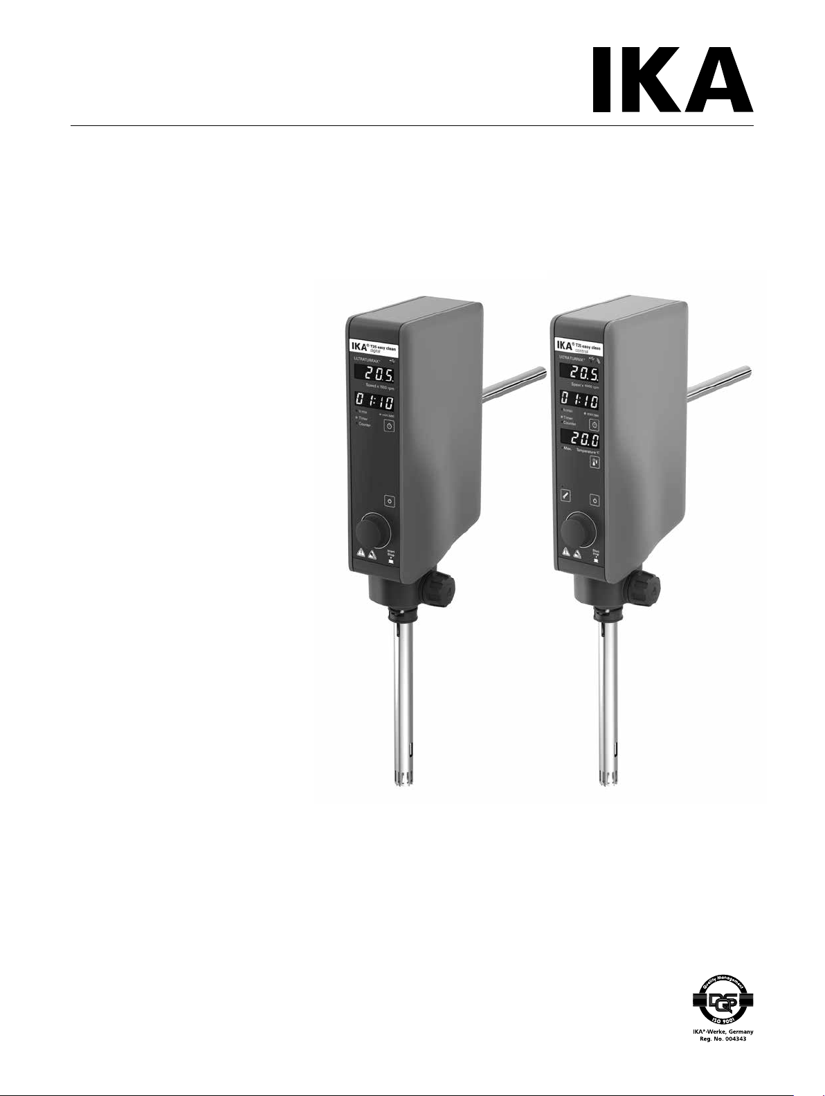
IKA T25 easy clean digital
IKA T25 easy clean control
Operating instructions EN
Page 2
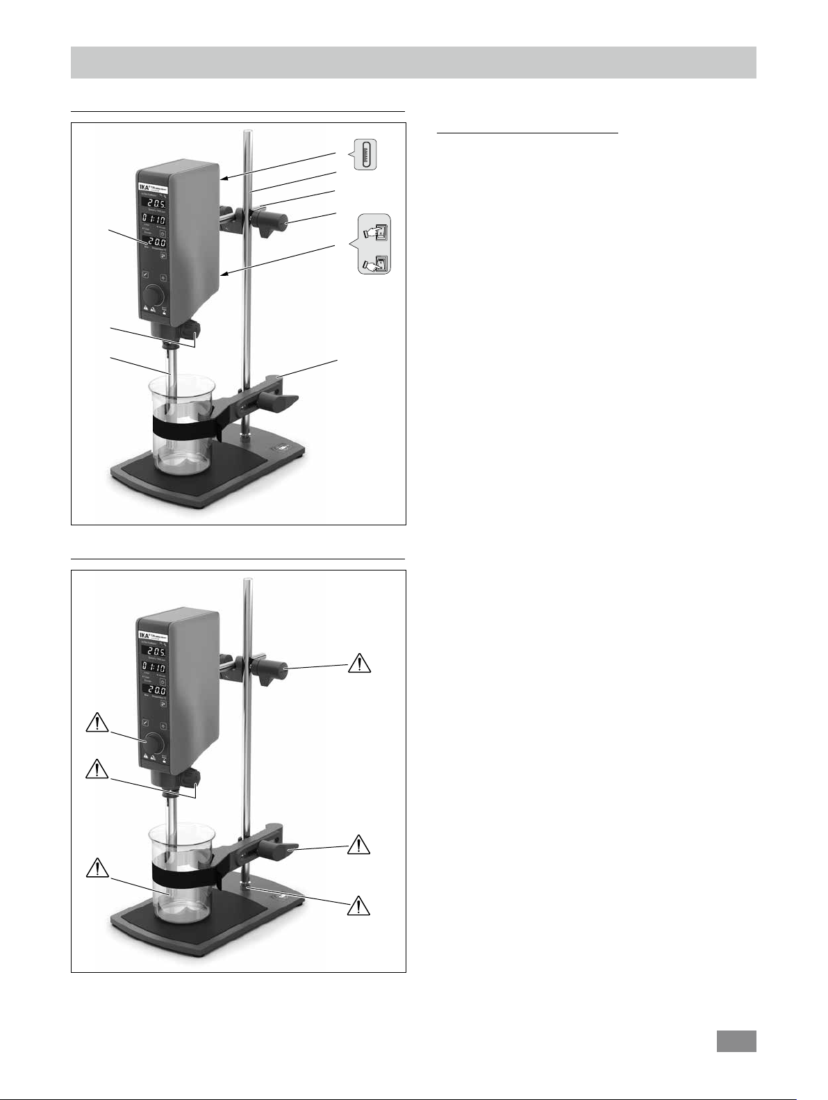
Device setup
On
Off
1
2
Device setup/Dangerous parts
Item Designation
4
5
6
7
8
1 Operator panel and display
2 Turning knob
3 Dispersion tool
4 USB port
5 Stand
6 Extension arm
7 Cross sleeve
8 Power switch
9 Strap clamp
3
Fig. 1
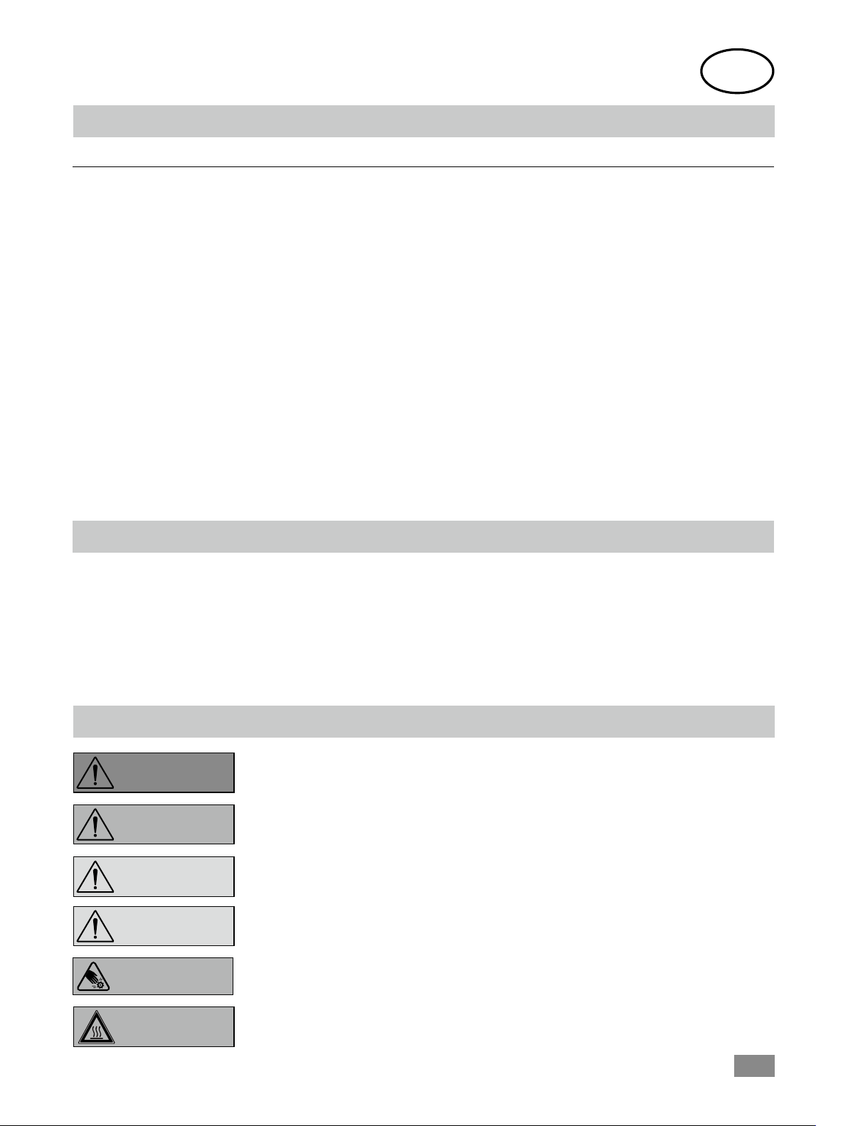
Dangerous parts
9
Fig. 2
2
Page 3
Source language: German
EN
Contents
Page
Device setup/Dangerous parts 2
Declaration of conformity 3
Explication of warning symbols 3
Safety instructions 4
Intended use 5
Unpacking 6
Useful information 6
Drive 6
Securing 7
Operator panel and display 8
Commissioning and operating 10
Interfaces and outputs 12
Accessories 13
Permitted dispersion tools 13
Warning message 14
Error codes 14
Maintenance and cleaning 15
Technical data 16
Warranty 16
EU Declaration of conformity
We declare under our sole responsibility that this product corresponds to the directives 2014/35/EU, 2006/42/EC, 2014/30/
EU and 2011/65/EU and conforms with the following standards or normative documents: EN 61010-1, EN 6010-2-051,
EN 61326-1, EN 60529 and EN ISO 12100.
Bluetooth® module (for T25 easy clean control):
Directive: 2014/53/EU Standards: EN 60950-1, EN 300328, EN 301489-1, EN 301489-17
A copy of the complete EU Declaration of Conformity can be requested at sales@ika.com.
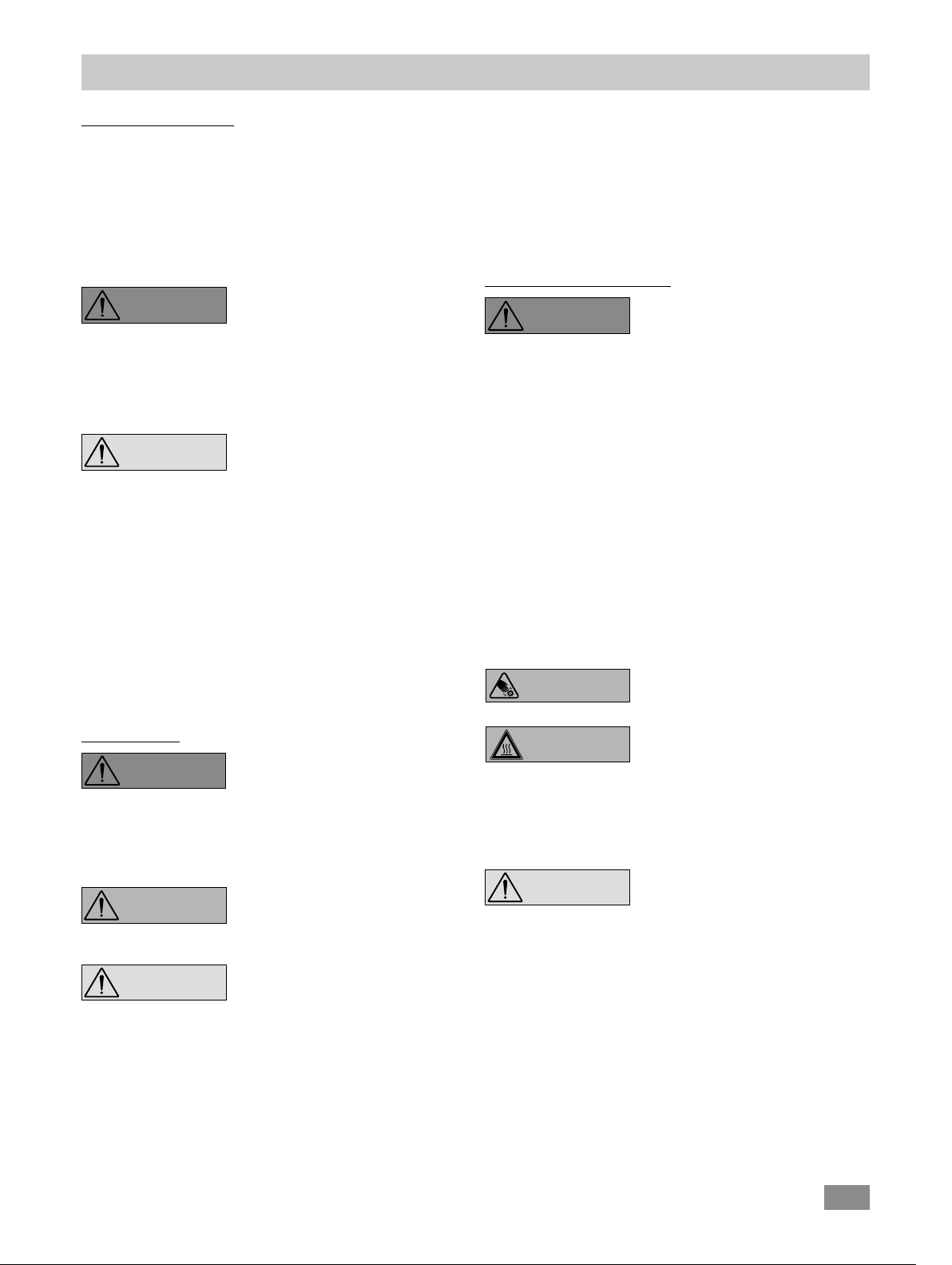
Explication of warning symbols
indicates a hazardous situation which, if not avoided, will result in death or serious injury.
DANGER
indicates a hazardous situation which, if not avoided, could result in death or serious injury.
WARNING
used with the safety alert symbol, indicates a hazardous situation, which, if not avoided,
CAUTION
could result in minor or moderate injury.
is used to address practices not related to personal injury.
NOTICE
WARNING
WARNING
Indicates crushing risk to fingers/hand.
Indicates hazards arising from a hot surface.
3
Page 4
Safety instructions
General information:
• Read the operating instructions in full before starting up and follow the safety instructions.
• Keep the operating instructions in a place where they can
be accessed by everyone.
• Ensure that only trained staff work with the device.
• Follow the safety instructions, guidelines, occupational
health and safety and accident prevention regulations.
DANGER
Beware of the risk of:
- flammable materials
- glass breakage
- sharp edges on the dispersing tool.
CAUTION
processed. There is a risk from:
- splashing and evaporation of liquids
- body parts, hair, clothing and jewellery getting caught.
• The device must only be used in a technically perfect condition.
• Do not cover the ventilation slots on the drive in order to
ensure adequate cooling of the drive.
• The voltage stated on the type plate must correspond to
the power voltage.
• Abrasion of the dispersion equipment or the rotating accessories can get into the medium you are working on.
Please pay attention to the dangerous parts of the equipment in Fig. 2.
Wear your personal protective
equipment in accordance with the
hazard category of the media to be
• Before switching on the dispersing device make sure that
the dispersion tool shaft is immersed in the medium. Observe the operating instructions of the dispersion tools.
• The distance between the dispersion tool and the vessel
bottom should not be less than 10 mm.
• Use the dispersion tool always inside the dispersing vessel.
• Do not use the device without a dispersion tool.
Working with the device:
DANGER
With substances capable of forming an explosive mixture,
appropriate safety measures must be applied, e.g. working under a fume hood.
To avoid body injury and property damage, observe the
relevant safety and accident prevention measures when
processing hazardous materials.
Only process media that will not react dangerously to the
extra energy produced through processing. This also applies to any extra energy produced in other ways, e.g.
through light irradiation.
The device is not suitable for hand-held operation.
Switch off the device at the power switch (item 8) or pull
out the mains plug when changing or handling the dispersing tool.
WARNING
Do not use the device in explosive
atmospheres, it is not EX-protected.
Do not touch rotating parts during
operation!
Device setup:
DANGER
If access to the power switch cannot be ensured, an additional emergency stop switch that can be easily accessed
must be installed in the work area.
WARNING
NOTICE
• Ensure that the dispersion tool is securely properly into
the drive unit.
• All screw connections must be properly tightened.
• Check that the turning knobs are secure and tighten if
necessary.
• Glass vessels must always be secured with a clamp to prevent them spinning.
The power switch of the IKA device
must be accessed immediately, directly and without risk at any time.
Make sure that the unit is stably
mounted. The vessel used for dispersing must be secured.
Set up the stand in a spacious area
on an even, stable, clean, non-slip,
dry and fireproof surface.
WARNING
If a dispersion tool is not inserted into the drive flange as
far as the mark it can become extremely hot in operation
and thus suffer damage.
CAUTION
speed and increase it gradually.
Reduce the speed if the medium splashes out of the vessel
because the speed is too high.
If the interaction between the medium and dispersing
element or working with dispersing tools with a stator
diameter ≥18 mm and a speed of more than 20000 rpm,
makes a loud noise, be sure to wear your personal protective equipment.
The dispersing tool and the coupling flange can become hot during
the operation.
Be aware that the unit starts with the
set speed, which is shown on the display. If uncertain start with the lowest
4
Page 5

NOTICE
eration. This will prevent the infiltration of foreign objects,
liquids and other contaminants.
Never run dispersion tools dry, as the gasket and bearings will be destroyed if the tools are not cooled by the
medium.
• In the event of unbalance or unusual noises, switch off
the device immediately. Replace the dispersion tool. If
there is no difference after the change of the dispersion
tool, return it to the dealer or the manufacturer along
with a description of the fault.
• Ensure that the stand does not start to move.
• Meter powder cannot be placed too close to the flange.
Powder can be blown away by air turbulences of the drive.
• There may be electrostatic discharges between the medium and the dispersing device shaft which could pose a
direct danger.
Covers or parts that can be removed
from the device without tools must
later be refitted to ensure safe op-
Power supply / Switching off the device:
• The device can only be disconnected from the power supply by pulling out the power plug or the connector plug.
• Always disconnect the plug before fitting accessories or
cleaning.
• The socket for the power cord must be easily accessible.
• The device does not start up again automatically following a cut in the power supply.
• The device must only be opened by trained specialists,
even during repair. The device must be unplugged from
the power supply before opening. Live parts inside the
device may still be live for some time after unplugging
from the power supply.
Accessories:
• Protect the device and accessories from bumps and impacts.
• Check the device and accessories beforehand for damage
each time you use them. Do not use damaged components.
• Only dispersion tool approved by IKA may be used.
• Safe operation is only guaranteed with the accessories described in the ”Accessories” chapter.
Disposal of the device:
• The device must be disposed of in accordance with national
regulations
Intended use
Use:
When used in combination with one of our recommended
dispersion tools, the drive unit is a high-speed dispersing
and emulsifying unit capable of handling free-flowing and
liquid media in batches.
Production of:
Emulsions
Dispersions
Wet crushing
Intended use: on stand (dispersion tool points down)
Range of use (indoor use only):
- Laboratories - Schools
- Pharmacies - Universities
The device is suitable for use in all areas (EMC class A and B).
The safety of the user cannot be guaranteed:
- If the device is operated with accessories that are not sup-
plied or recommended by the manufacturer
- If the device is operated improperly or contrary to the
manufacturer’s specifications
- If the device or the printed circuit board are modified by
third parties.
5
Page 6
Unpacking
R
O
T
O
R
S
T
A
T
O
R
Unpacking:
- Unpack the device carefully.
- Any damage should be notified immediately to the shipping
agent (post oce, railway network or logistics company).
Useful information
Dispersion is the dissolution and diffusion of a solid, liquid
or gaseous phase in a liquid that is not consolute with that
phase.
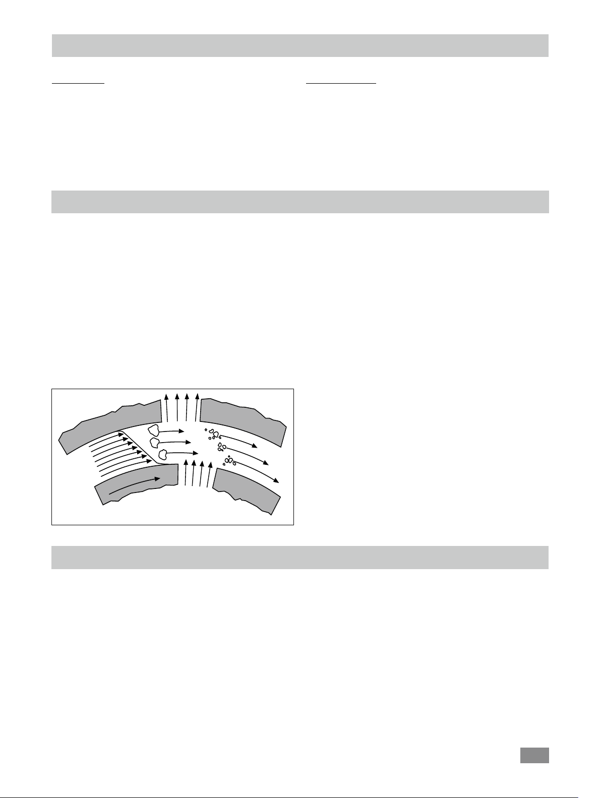
The rotor/stator principle:
Due to the high rotation speed of the rotor, the medium
to be processed is automatically drawn axially into the dispersion head and then forced radially through the slots in
the rotor/stator arrangement. The high accelerations acting
on the material produce extremely strong shear and thrust
forces. In addition, high turbulence occurs in the shear gap
between rotor and stator, which provides optimum mixing
of the suspension.
Delivery scope:
- IKA T 25 easy clean digital or IKA T 25 easy clean control
- Extension arm
- Hexagon socket screw
- Screwdriver DIN 911
- USB 2.0 cabel (A – micro B)
- User guide
- Warranty card.
The dispersion effectiveness is heavily dependent on the
product of the shear gradient and the time the particles
spend in the shear zone. The optimum range for the circumferential velocity of the rotor/stator arrangement is
6–24 m/s.
A processing time of a few minutes is usually sucient to
produce the desired fineness. Long processing times bring
only insignificant improvements in the obtainable fineness;
the energy expended serves merely to increase the temperature of the medium.
Fig. 3
The drive unit opens up a wide range of possibilities for dispersion technology in the conventional laboratory with a
respective performance output of approximately 400 watts
at 25000 rpm.
Drive
The speed is set by using the operating knob. The motor
speed can be read from the LED display. For example, a value of 13.6 corresponds to 13600 rpm.
6
Page 7

Securing
Securing the extension arm to the disperser:
Disperser
Hexagon socket
offset screw key
Hexagonal socket
screw
Extension arm
Fig. 4
Ensure that the extension arm is fitted securely.
Vibration may cause the screw to become loose. It is therefore necessary for safe use to regularly check that the extension arm is attached securely. Tighten the hexangular bolt
as required.
Securing the disperser to the stand:
Cross sleeve
Screw bolt
Extension
arm
Securing the dispersion tool:
Drive unit
!
0 mm
Turning knob
!
Dispersion tool
Fig. 6
Open the turning knob so that the thread does not protrude
into the hole.
Insert the dispersion tool from the bottom into the drive
unit as far as the stop. The shaft tube will audibly click into
place when a small amount of force is applied.
The dispersion tool is fitted correctly when the marking on
the dispersing element is aligned with the bottom edge of
the drive unit.
Now secure the dispersion tool by screwing the turning
knob tightly.
Securing the dispersing vessel to the stand:
Stand
Fig. 5
Check that the disperser is held in position firmly prior to
each use and also at regular intervals. The position of the
disperser must only be adjusted when the equipment is stationary and the power supply is disconnected.
Stand
Strap clamp
Clamping bolt
Clamping
band
Vessel
Fig. 7
7
Page 8

T25 easy clean digital:
Operator panel and display
Item Designation
A "Speed" display: Display the "Speed" value (x 1000 rpm).
B "Timer/Counter" display:
Q
A
B
C
D
E
C "h:min" indicator:
P
D "Timer" indicator:
E "Counter" indicator:
K "Start/Stop" knob:
O
Start/stop dispersing function.
N
L
M
L
On/off button: Switch on/off the device.
M "Timer" button:
N "min:sec" indicator:
O "Timer" setting indicator: Indicate the "Timer" can be set
P "Speed" setting indicator: Indicate the speed can be set
When the device is controlled by Labworldsoft and
Q USB indicator:
Indicate the "Timer" or "Counter" is in hour/minute
Indicate the "Counter" function is activated.
Switch between the setting of speed and timer.
Function
Indicate the "Timer/Counter" value.
[h:min] mode.
Indicate the "Timer" function is activated.
Set the speed.
Set the timer when "Timer" setting is activated.
Indicate the "Timer" or "Counter" is in minute/second
[min:sec] mode.
.
.
tries to change the speed of the device, the display
show PC
Indicates the device is connected to a PC with USB port.
( )
.
Fig. 8
K
8
Page 9

T25 easy clean control:
A
B
C
D
E
F
G
H
I
J
Fig. 9
easy clean
Item Designation Function
R
Q
P
A "Speed" display: Display the "Speed" value (x 1000 rpm).
B "Timer/Counter" display: Indicate the "Timer/Counter" value.
Indicate the remaining time to maintenance.
When device is controlled by a WiCo, the dis-
play show rC ( ) .
O
N
M
C "h:min" indicator: Indicate the "Timer" or "Counter" is in hour/
minute [h:min] mode.
D "Timer" indicator: Indicate the "Timer" function is activated.
E "Counter" indicator:
F "Temperature" display:
Indicate the "Counter" function is activated.
Display the actual temperature value/set max.
temperature value of the medium with the
S 25 EC-T... tool.
If a tool other than the S 25 EC-T... is used,
the display show ---.
G "Max. Temperature" indicator: Indicate the "Max. Temperature" of the dis-
L
persing medium that can be set.
H "Max. Temperature" button: Display the max. temperature setting in run-
ning status.
K
Active the setting function on "Max. Temper-
ature" of the dispersing medium.
I
S 25 EC-T...
dispersion tool indicator: Indicate the S 25 EC-T... dispersion tool is in-
serted.
J
S 25 EC-T...
dispersion tool button: Display the remaining time to maintenance
of
S 25 EC-T...
tool
.
Activate the reset of the maintenance time.
K "Start/Stop" knob: Set the speed value by rotating the knob.
Set the timer value by rotating the knob when
"Timer" setting is activated.
Start/stop the running of the device by press-
ing the knob.
L On/off button: Switch on/off the device.
M "Timer" button: Activate the "Timer" setting.
N "min:sec" indicator: Indicate the "Timer" or "Counter" is in minute/
second [min:sec] mode.
O "Timer" setting indicator: Indicate the "Timer" can be set by rotating the
knob.
P "Speed" setting indicator: Indicate the speed can be set by rotating the
knob.
When the device is controlled by Labworld-
soft and tries to change the speed of the device, the display show PC ( ).
Q USB indicator: Indicates the device is connected to a PC with
the USB port.
R Bluetooth indicator: Indicates the device is communicating with a
WiCo or a PC via the bluetooth.
9
Page 10

Commissioning and operating
Refer to the operating instructions for the filling level of the
medium and the immersion depth into the dispersion tool
used.
If a dispersion tool is not inserted into the drive flange as far
as the mark it can become extremely hot in operation and
thus suffer damage.
So as to avoid unintentional ingress of air into the medium
due to excessively turbulent rotation, the whole unit can be
placed a little off center in the dispersing vessel.
Switching on:
After switching on the power switch (8) of the device, all LED segments light up during self test.
Then, "Timer" display (B) shows the software version.
After that, the device enters standby status and "Speed" setting indicator (P) keeps lighting.
Setting speed:
Activate the device by pressing on/off button (L).
After a beep, the "Speed" setting indicator (P) lights up.
Change the speed setting by rotating the "Start/Stop" knob (K).
The speed value shows on the display (A), e.g.: means the speed is 3200 (3.2 x 1000) rpm.
Start the device by pressing the "Start/Stop" knob (K).
Check whether the voltage given on the type plate corresponds to the available power voltage.
The socket used must be earthed (fitted
with earth contact).
If these conditions have been met, the machine is ready to
operate when the power plug is plugged in.
If these conditions are not met, safe operation is not guaranteed and the machine could be damaged.
Note: After starting, actual speed value flashes until reach the set value.
Setting timer:
Activate the timer setting by pressing timer button (M).
Timer setting indicator (O) lights up.
Change the timer setting by rotating the "Start/Stop" knob (K).
When the timer is set to over 00:00, the timer function is activated and timer indicator (D)
lights up.
The "min: sec" indicator (N) and "h:min" indicator (C) show the unit of the timer value.
Start the device by pressing the "Start/Stop" knob (K).
When the time reach 00:00, the device stops running and the display (A) and (B) show last
settings.
Note: While running, the timer setting can be checked by pressing the timer button (K).
Activating the counter function:
Set the timer to 00:00 [min:sec] by rotating
The counter function is activated and counter indicator (E) lights up.
Start the device by pressing
the
"Start/Stop" knob (K).
the
"Start/Stop" knob (K).
10
Page 11

For T25 easy clean control with
Setting the "Max. Temperature":
Activate the setting function of maximum temperature of the dispersing medium by pressing
"Max. Temperature" setting indicator (G) lights up.
Change the setting by rotating the "Start/Stop" knob (K).
Start the device by pressing the "Start/Stop" knob (K).
Note: When the dispersing medium reaches the set temperature, the device stops and a warning
message is shown on display (A) and (B): hot tool (see section "Warning message").
While running, the "Max. Temperature" setting can be checked by pressing the "Max. Temperature" button (H).
Checking the tool maintenance time:
To
Display (B) shows the tool maintenance time about 2 seconds.
The "min: sec" indicator (N) or "h:min" indicator (C) show the unit of the time value.
Display (B) switches to show the timer value.
Note: The tool maintenance time can be checked in either stop or running status.
When the tool maintenance time is less than 30 minutes, the
cator (I) changes from green to red color.
When the tool maintenance time reaches 0, the value (00:00:00) flashes and meanwhile the
indicator LED (I) is red and flashes.
S 25 EC-T...
"Max. Temperature" button (H).
check the tool maintenance time of
tool button (J).
S 25 EC-T...
dispersion tool only:
S 25 EC-T...
dispersion tool indicator (I) flashes twice.
by pressing
S 25 EC-T...
S 25 EC-T...
dispersion tool indi-
dispersion
Resetting the tool maintenance time:
The default maintenance time of
maintenance (e.g. replacing the bearing) to the dispersion tool when the service time elapse.
When the tool maintenance time reach 0, the device will not stop, but we recommend a maintenance of the tool as soon
as possible. After the maintenance in a IKA service workshop the maintenance time will be reset from the service team. In
all other cases it is possible to reset the maintenance time with the device. Description see below.
* Note: The maintenance time of S 25 EC-T… dispersion tool can be set between 4 to 40 hours according to the request
of your application by rotating the "Start/Stop" knob immediately after resetting the tool maintenance time. The new
value has to confirm by pressing the "Start/Stop" knob. This new value will be the resetting value when the tool will reset
the next time.
S 25 EC-T...
Activate the setting function on the tool maintenance time of
by pressing
Display (B) switches to tool maintenance time.
The
S 25 EC-T...
Press the "Start/Stop" knob (K) to reset the tool maintenance time.
dispersion tool is 20* hours. We recommend to check and carry out necessary
S 25 EC-T...
dispersion tool indicator (I) flashes.
dispersion tool button (J) 3 seconds.
S 25 EC-T...
dispersion tool
11
Page 12

Interfaces and outputs
Remote control:
The device can be connected to a PC using a USB cable and
be operated in “Remote” mode via USB port using labworld-
soft® laboratory software.
The device software can also be updated with a PC via the
USB port.
Note: Please observe the system requirements together
with the operating instructions and help section included
with the software.
USB interface:
The Universal Serial Bus (USB) is a serial bus for connecting
the device to the PC. Equipped with USB devices can be
connected to a PC during operation (hot plugging). Connected devices and their properties are automatically recognized. The USB port can also be used to update firmware.
USB device drivers:
First, download the latest driver for IKA devices with USB
port from:
http://www.ika.com/ika/lws/download/usb-driver.zip.
Install the driver by running the setup file. Then connect the
IKA device through the USB data cable to the PC.
The data communication is via a virtual COM port.
Device software update:
For device software update, visit IKA website www.ika.
com and enter the "Service" menu. Download and run the
Firmware Update Tool.
Find and click the Firmware Update Tool in your PC after
installation. Register your E-mail and password.
Connect the device to your PC via the USB cable. Then, you
can update the device software according to instructions of
the Firmware Update Tool.
Command syntax and format:
The following applies to the command set:
- Commands are generally sent from the computer (Master)
to the device (Slave).
- The device sends only at the computer’s request. Even
fault indications cannot be sent spontaneously from the
device to the computer (automation system).
- Commands are transmitted in capital letters.
- Commands and parameters including successive parameters are separated by at least one space (Code: hex 0x20).
- Each individual command (incl. parameters and data) and
each response are terminated with Blank CR LF (Code: hex
0x0d hex 0x0A) and have a maximum length of 80 characters.
- The decimal separator in a number is a dot (Code: hex
0x2E).
The above details correspond as far as possible to the recommendations of the NAMUR working party (NAMUR recommendations for the design of electrical plug connections for analogue and digital signal transmission on individual items of
laboratory control equipment, rev. 1.1).
The NAMUR commands and the additional specific IKA commands commissioning serve only as low level commands for
communication between the tube driver and the PC. With a suitable terminal or communications program these com-
®
mands can be transmitted directly to the tube driver. The IKA software package, Labworldsoft
, provides a convenient tool
for controlling tube driver and collecting data under MS Windows, and includes graphical entry features, for motor speed
ramps for example.
Commands Function
IN_NAME Read device name.
RESET Switch to normal operation mode
IN_PV_4 Read current speed value
IN_SP_4 Read rated value
OUT_SP_4 X
Adjust the rated speed value
(X = 3000 ... 25000)
START_4
Start the motor
STOP_4 Stop the motor
IN_SOFTWARE Read software ID and version
12
Page 13

Accessories
R 1825 Plate stand
R 1826 Plate stand
R 1827 Plate stand
R 182 Cross sleeve
RH 3 Strap clamp
See more accessories on www.ika.com.
Permitted dispersion tools
Dispersion tools series S 25...
Abbreviations:
S 25: consistent with all dispersing units T 25...
N: PTFE bearing
KV:
D: Without seal
KD: Ball bearing with PTFE bearing with seal
T: Temperature
C: Ceramic bearing
KS: Synthetic material
ST: Saw tooth
EC: easy clean
Ball bearing with axial face seal (suitable for vacuum up to 1 mbar, 6 bar excess pressure)
BC 1000 Beaker cap
Silentstream
T 25 easy clean control WiCo (for T25 easy clean control
only)
S 25 EC - C - 18G - ST Stainless steel
S 25 EC - T - C - 18G - ST Stainless steel
(S 25 EC only suitable for T25 easy clean digital or
T25 easy clean control. Full functionality of the S 25 EC-T
... only with the T25 easy clean control
Note below dispersing status and cleaning status!
).
8G, 10G, 18G, 14G, 25G, 25F:
Stator / shaft tube diameter
G: Coarse
F: Fine
Speed range: up to 25000 rpm
Designation Shaft material
S 25 N - 8G Stainless steel
S 25 N - 10 G Stainless steel
S 25 N - 18 G Stainless steel
S 25 N - 25 G Stainless steel
S 25 N - 25 F Stainless steel
S 25 N - 8G - ST Stainless steel
S 25 N - 10 G - ST Stainless steel
S 25 N - 18 G - ST Stainless steel
S 25 N - 25 G - ST Stainless steel
S 25 KV - 18 G Stainless steel
S 25 KV - 25 G Stainless steel
S 25 KV - 25 F Stainless steel
S 25 D - 10 G - KS Synthetic material
S 25 D - 14 G - KS Synthetic material
S25 KD - 18 G Stainless steel
S25 KD - 25 G Stainless steel
S25 KD - 25 F Stainless steel
S25 KD - 18 G - ST Stainless steel
S25 KD - 25 G - ST Stainless steel
Dispersing status Cleaning status
For applications and further information, please see the operating instructions of the dispersion tools.
Only use the dispersion tools listed and observe the
operating instructions of the dispersion tool.
13
Page 14

Warning message
Any malfunction during operation may be identified by an warning message on the display.
Proceed as follows in such cases:
Warning code Cause Effect Solution
The dispersion tool is not secured
no
properly.
tool
motor off - Secure the dispersion tool properly.
- Restart the device by pressing the "Start/Stop" knob (F).
The medium temperature exceeds
hot
the maximum temperature setting.
(only for S 25 EC-T...).
tool
motor off - Switch off the device using on/off button (L).
- Switch on the device again using on/off button (L).
- Let the medium and dispersion tool cool down or set
higher maximum temperature.
-
Restart the device by pressing the "Start/Stop" knob (K).
Error codes
Any malfunction during operation may be identified by an error message on the display.
Proceed as follows in such cases:
Switch off device using the power switch
Carry out corrective measures
Restart the device.
Error code Cause Effect Solution
E 3 Inside temperature is too high motor off
E 4 Motor can’t run normal (can’t start
or not reach the target speed)
E 25
E 86
E 47
E 48
Internal hardware failure motor off - Send the
Overload motor off - Switch off the
motor off - Switch off the
- Switch off the device and let it cool down.
- Restart the
- Check the structure for possible blockage
- Decrease the speed setting or the load
device
device
.
device.
for repair.
device
If the actions described fails to resolve the fault or another error code is displayed then take one of the following steps:
- Contact the service department
- Send the device for repair, including a short description of the fault.
14
Page 15

Maintenance and cleaning
The device is maintenance-free. It is only subject to the natural wear and tear of components and their statistical failure
rate.
Cleaning:
For cleaning disconnect the main plug!
Use only cleaning agents which have been approved by IKA
to clean IKA devices.
Dirt Cleaning agent
Dye isopropyl alcohol
Construction material water containing tenside/isopropyl alcohol
Cosmetics
Foodstuff
Fuel
water containing tenside/isopropyl alcohol
water containing tenside
water containing tenside
For materials which are not listed, please request information from IKA application support.
Wear protective gloves during cleaning the device.
Electrical device may not be placed in the cleansing agent
for the purpose of cleaning.
Do not allow moisture to get into the device when cleaning.
Before using another than the recommended method for
cleaning or decontamination, the user must ascertain with
IKA that this method does not destroy the device.
Spare parts order:
When ordering spare parts, please give:
- machine type
- manufacturing number, see type plate
- item and designation of the spare part see www.ika.com
- software version.
Repair:
Please send in device for repair only after it has been
cleaned and is free from any materials which may
constitute a health hazard.
For repair, please request the “Decontamination Certificate” form IKA or use the download printout of it from
IKA website: www.ika.com.
If you require servicing, return the device in its original packaging. Storage packaging is not sucient. Please also use
suitable transport packaging.
15
Page 16

Technical data
T25 easy clean digital T25 easy clean control
Operating voltage VAC 220 ... 240 ± 10 %
100 ... 120 ± 10 %
Frequence Hz 50 / 60
Motor rating input W 500
Motor rating output W 400
Volume range (H
Maximum viscosity
Speed range rpm 3000 ... 25000
Speed deviation ± 2% of current speed
Speed display LED
Speed adjustment stepless
Noise without dispersion tool dB (A) ≤ 70
Extension arm (Ø x L) mm 13 x 160
Temperature display no LED
Temperature display resolution °C - 0.1
Timer function yes
Timer display LED
Permit on time % 100
Dimension (W x D x H) mm 89 x 161 x 270
Weight kg 3.0
Permissible ambient temperature °C + 5...+ 40
Permissible relative humidity % 80
IP code according to EN 60529 IP 30
Interface USB USB, bluetooth
Operation at a terrestrial altitude m maximum 2000
O) l 0.001 ... 2
2
mPa•s
5000
Subject to technical changes!
Warranty
In accordance with IKA warranty conditions, the warranty
period is 24 months. For claims under the warranty please
contact your local dealer. You may also send the machine
direct to our factory, enclosing the delivery invoice and giving reasons for the claim. You will be liable for freight costs.
The warranty does not cover worn out parts, nor does it
apply to faults resulting from improper use, insucient care
or maintenance not carried out in accordance with the instructions in this operating manual.
16
Page 17

IKA-Werke GmbH & Co.KG
Janke & Kunkel-Str. 10
D-79219 Staufen
Tel. +49 7633 831-0
Fax +49 7633 831-98
sales@ika.de
www.ika.com
 Loading...