

Page 1
20000004637
IKA® RW 47 digital
Operating instructions EN
Reg.-No. 4343-01
Page 2
Drehmoment der Abtriebswelle
Grenzkurve Getriebestufe II
Anschluss-Sicherheitsendschalter
connection-limit switch
A
B
D
Rotating
direction!
E
Anschluss-Netz
connection-power supply
C
Fig. 1
M
[Nm]
55
50
40
35
30
25
Drehmoment der Abtriebswelle
Torque at output shaft
20
15
F
Fig. 3
M
[Nm]
Drehmoment der Abtriebswelle
M
[Nm]
Grenzkurve Getriebestufe I
Limit curve gear level I
50
4040
30
20
10
Torque at output shaft
Drehzahl der Abtriebswelle
Torque at output shaft
Limit curve gear stage II
10
200100 n [rpm]
Fig. 2
10
Arbeitsbereich
Getriebestufe I
5
workspace
Gear Level I
0 200 400 600 800 1000 1200 1400
Arbeitsbereich
Getriebestufe II
workspace
Gear Level II
Drehzahl der Abtriebswelle
Output shaft speed
n [rpm]
5
Torque at output shaft
400 600 800 1000 1200
Drehzahl der Abtriebswelle
Torque at output shaft
n [rpm]
2
Page 3
Rotating
direction!
G
M
Fig. 4
H
J
J
I
L
K
Fig. 5
Fig. 8
3
Page 4
3 (2x)
12(1x)
SI 400
1975
1973
(3x)
230/400V
50/60 Hz
5 (2x)
8 (2x)
9 (2x)
11(1x)
SI 472
(1x)
6 (2x)
1 (2x)
2 (2x)
10
5
8
7 (2x)
4 (2x)
3
2*
4
3
+
ΔL
–
12
2*(1x)
SI 400
1973 (2x)
(2x)
1975
2
2
2
4
1*
6 7
SI 400
SI 472
5
8
9
1
9
6
10
1
1*(1x)
SI 400
(3x)
230/400V
50/60 Hz
Fig. 6
4
Page 5
4
(2x)
4 (1x)
2 2 (4x)
7
3
MIN 5 mm
MAX 8 mm
8
5 (1x)
SI 474
(2x)
1973
3
3 (4x)
1 (2x)
5
2 2
2
1
3
6 7
+
2
2
4
ΔL
7
3
–
2*(1x)
SI 400
1975 (2x)
5
1
1*(1x)
1
2*
3
(3x)
SI 400
230/400 V
50/60 Hz
SI 474
SI 400
5
4
3
7
1*
Fig. 7
5
Page 6
Source language: German
EN
Contents
Page
EC-Declaration of conformity 6
Explication of warning symbols 6
Safety instructions 7
Correct use 9
Unpacking 9
Useful information 9
Drive 9
Motor circuit breaker 10
Gear speed change 10
Output shaft 10
Speed display 10
Commissioning 10
Securing 11
Switching on the instrument 11
Maintenance and cleaning 12
Error codes 13
Warranty 13
Accessories 13
Permitted IKA® stirrer tools 13
Technical data 14
Wiring diagram 15, 16
EC-Declaration of conformity
We declare under our sole responsibility that this product corresponds to the regulations 2006/42/EC and 2004/108/ EC and
conforms with the standards or standardized documents: EN 61010-1, -2-051; EN 12 100-1, -2;
60204-1.
EN 61326-1 and EN
Explication of warning symbols
General hazard
DANGER
WARNING
CAUTION
This symbol identifies information that is of vital importance for safeguarding your health
and safety. Disregarding this information can lead to health impairment and injuries.
This symbol identifies information that is of importance for the technically correct functioning
of the system. Disregarding this information can result in damage to the instrument or to system
components.
This symbol indicates information which is important for ensuring that the operations of the
instrument
information can result in inaccurate results.
are performed eciently and for using the instrument. Failure to observe this
6
Page 7

Safety instructions
•
Read the operating instructions in full before
starting up and follow the safety instructions.
• Keep the operating instructions in a place where
it can be accessed by everyone.
• Ensure that only trained staff work with the instrument.
•
Follow the safety instructions, guidelines, occupational health and safety and accident prevention regulations.
• Because the options for combining products,
tools, stirring vessel, experiment and medium
are nearly endless, user safety cannot be ensured simply with design requirements on the
part of the product. For this reason, it may
become necessary for users to take other precautionary safety measures. For example, glass
devices or other stirring vessels that are sensitive
to mechanical stress can be damaged or shattered by an imbalance, increasing the speed too
quickly or too little distance between the stirring
element and the stirring vessel. Users can suffer
serious injury from glass breakage or from the
freely rotating stirring element.
• Uncontrolled reactions can be triggered by mixing the heated material insuciently or by the
energy generated by selecting a speed that is
too high. In case of these and other increased
operational hazards, users must take additional
appropriate safety precautions (e.g. shatter protection). In any case, when using critical or hazardous materials in your processes, IKA® recommends to use additional appropriate measures
to ensure safety in the experiment. For example,
users can implement measures that inhibit fire
or explosions or comprehensive monitoring
equipment. Furthermore, users must make sure
that the OFF switch of the IKA® product can be
accessed immediately, directly and without risk
at any time, and above all, in case of fault.
DANGER
• Only process media that will not react dangerously to the extra energy produced through
processing. This also applies to any extra energy
produced in other ways, e.g. through light irradiation.
If installation or positioning
cannot ensure this access
at all times, an additional
EMERGENCY STOP switch
that can be easily accessed
must be installed in the work
area.
•
Do not operate the instrument in explosive atmospheres, with hazardous substances or under
water.
•
Process pathogenic materials only in closed ves-
sels under a suitable fume hood. Please contact
IKA® application support if you have any ques-
tion.
•
The instrument is not suitable for manual operation.
•
The high torque developed by the RW 47 digital
requires particular care in the choice of stand, cross
sleeve and anti-rotation element for the agitating
vessel.
• Set up the stand in a spacious area on an even,
stable, clean, non-slip, dry and fireproof surface.
• You must ensure that the stirring element is securely clamped in the chuck!
•
Use stirring shaft protective equipment and a
safety cutout for height adjustable stands!
• The agitated vessels used for stirring have to be
secured. Consider on a good stability of the entire structure.
DANGER
•
Protect the instrument and accessories from
bumping and impacting.
• Check the instrument and accessories before-
hand for damage each time when you use
them. Do not use damaged components.
•
Safe operation is only guaranteed with the acces-
sories described in the ”Accessories” section.
• Always switch the main switch in the OFF position or disconnect the power before changing
stirring element and fitting allowed accessories.
• The instrument can only be disconnected from
the mains supply by pulling out the mains plug
or the connector plug.
• The socket for the mains cord must be easily
accessible.
•
Socket must be earthed (protective ground
contact).
•
The voltage stated on the type plate must cor-
respond to the mains voltage.
• Please observe the permitted speed for the stirring element. Never set higher speed.
• Make certain that the unit is set at the lowest
speed before commissioning; otherwise, the
unit will begin running at the speed set in last
operation. Gradually increase the speed.
• Pay attention when setting the speed to any
imbalance of the stirrer tools and possible
spraying of the medium to be stirred.
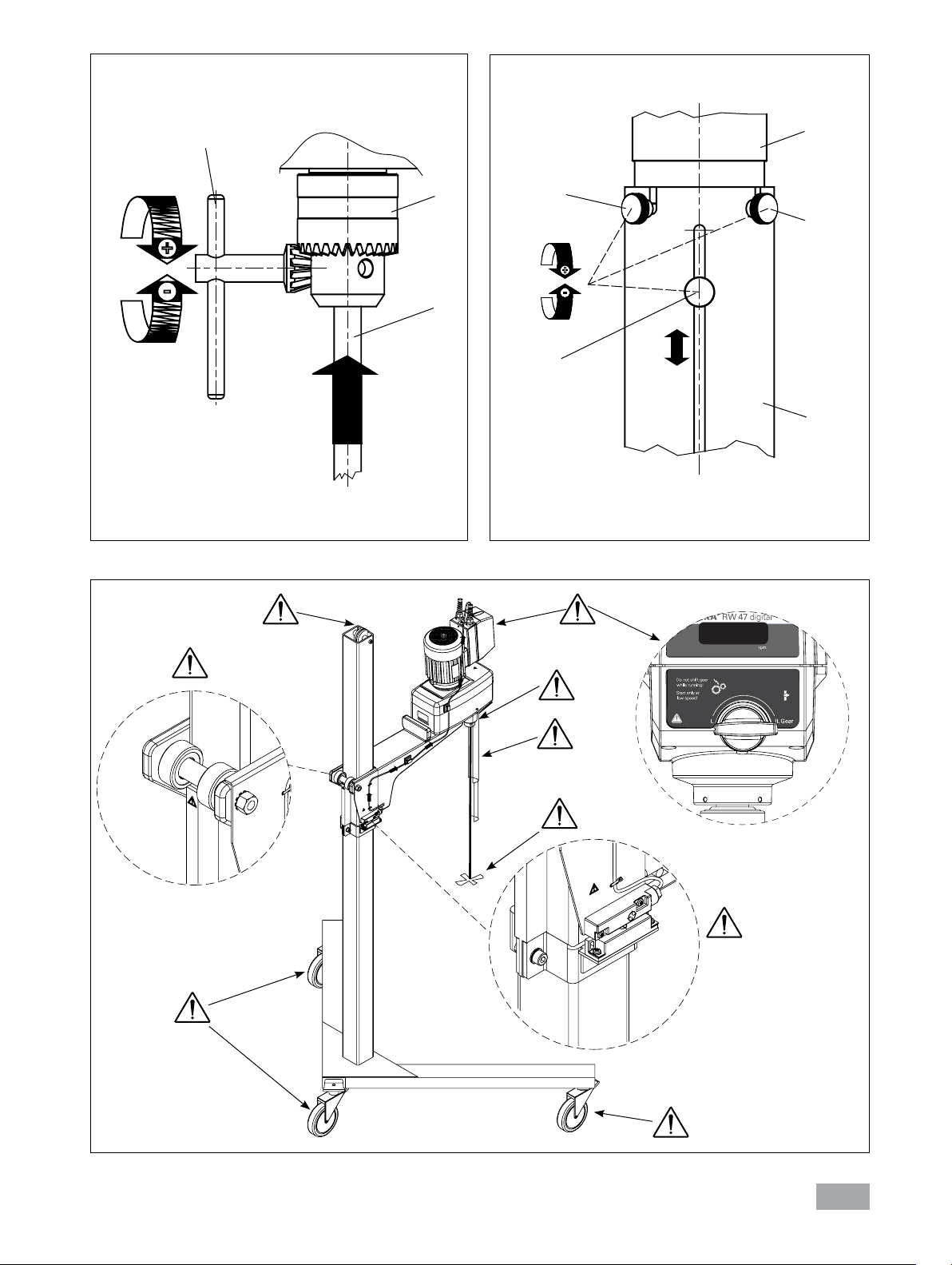
Please pay attention to
the dangerous parts of the
equipment in Fig. 8.
7
Page 8

DANGER
DANGER
DANGER
DANGER
DANGER
•
There may be electrostatic activity between the
medium and the output shaft which could cause
a direct danger.
• After an interruption in the power supply or a
mechanical interruption during a stirring process, the unit does not restart automatically.
• It is important to note that the surfaces of the
motor (cooling fins) and certain parts of the
bearing may get very hot during operation.
• Never cover the ventilation slots or cooling ns
on the motor as these are needed for cooling
the drive system.
• Avoid knocking and impacting on the lower end
of the shaft and the chuck gear teeth. Even minor, invisible damage can lead to imbalance and
uneven shaft action.
• Ensure that the stand does not start to move.
Never operate the instrument with the stirrer tools
rotating freely. Ensure that
parts of the body, hair, jewelry or items of clothing
cannot be trapped by the
rotating parts.
Wear your personal protective equipment in accordance with the hazard category of the medium to be
processed; otherwise there
is a risk of:
- splashing of liquids
- projectile parts
-
body parts, hair, clothing
and jewelry getting caught.
Beware of the risk of
- flammable materials
-
glass breakage as a result of
mechanical shaking power.
Reduce the speed if:
- the medium splashes out
of the vessel because the
speed is too high
- the instrument is not running smoothly
- the instrument begins to
move around because of
dynamic forces
- malfunction.
Do not touch rotating
parts during operation!
•
Imbalance of the output shaft, the chuck and
in particular the stirring tools can lead to uncontrolled resonant vibrational behavior of the
instrument and the whole assembly. Glass devices and stirrer containers can be damaged
or shattered by this. It can cause injury to the
operator, also can damage the rotating stirring
tool. In this case exchange the stirring tool for
one without imbalance or remedy the cause of
the imbalance.
it to the dealer or the manufacturer along with
a description of the fault.
• If the instrument is operated too long in overload or if the ambient temperature is too high,
the instrument switches off permanently.
• The machine must only be opened by trained
specialists, even during repair. The instrument
must be unplugged from the power supply before opening. Live parts inside the instrument
may still be live for some time after unplugging
from the power supply.
WARNING
WARNING
DANGER
• Before commissioning, the correct direction of
rotation of the motor must always be ensured
(test run without stirring tool: motor rotation as
indicated of the arrow on the front foil, clockwise rotation, looking down on motor). The
wrong direction of rotation can lead to the stirring tool coming off the shaft.
• If the unit is operated in different locations with
a 5-pin plug, the direction of rotation must be
checked before each commissioning, with no
stirring tool fitted.
If there is still imbalance, return
Covering or parts that are
capable of being removed
from the unit without accessory equipment have
to be reattached to the
unit for safe operation in
order to prevent, for example, the ingress of fluids, foreign matter, etc..
The unit must be switched
off (motor standstill) before changing to another
gear speed, otherwise the
toothed gears in the reduction stage will be damaged.
The equipment must be
wired by a qualified technician, otherwise there is a risk
of electric shock!
8
Page 9

Correct use
• Use
For mixing/stirring liquids with low to high viscosity by using various stirring tools.
Intended use: Stand device (Chuck downward).
• Range of use (indoor use only)
- Laboratories - Technical colleges
- Pharmacies - Small-scale production
Unpacking
• Unpacking
- Please unpack the device carefully
-
In the case of any damage a detailed report must
be sent immediately (post, rail or forwarder).
This equipment is suitable for use in all areas except:
- Residential areas
-
Areas that are connected directly to low-voltage
supply network that also supplies residential areas.
The safety of the user cannot be guaranteed:
- If the instrument is operated with accessories
that are not supplied or recommended by the
manufacturer
- If the instrument is operated improperly contrary
to the manufacturer’s specifications
- If the instrument or the printed circuit board are
modified by third parties.
• Delivery scope
- an RW 47 digital overhead stirrer
- an operating instructions
- four hexagonal socket screws
- a hexagon socket offset screw key
- a chuck key
- a warranty card
.
Useful information
You can set speed from 57 to 1300 rpm with the
50 Hz (mains frequency) and speed from 69 to
1560 rpm with the 60 Hz (mains frequency). The
unit may heats up during use. The ample cooling
surfaces on the motor serve to distribute and radiate the heat as evenly as possible.
You can also use large mixing vessels together
IKA® stands without any problem.
with
Drive
The motor can be infinitely adjusted via a friction
wheel drive unit but is operated in one position
only. The power output, rotational speed and
torque of the motor are regarded as constant and
are optimized for this operating position. After
the friction wheel drive the motor power output
is transmitted to the output shaft of the stirrer via
either the first or second stage of the subsequent
manually adjustable toothed gear train.
The unit comes without a connection cable because the user’s installation means that it is not
possible to issue a standard length cable due to
the different sizes of premises. Experts can determine the pin assignment from the wiring plan.
The output shaft is not designed as a hollow shaft
and allows inserting the stirring element until it
stops. It is important to ensure that the stirrer
shank is securely clamped in the chuck.
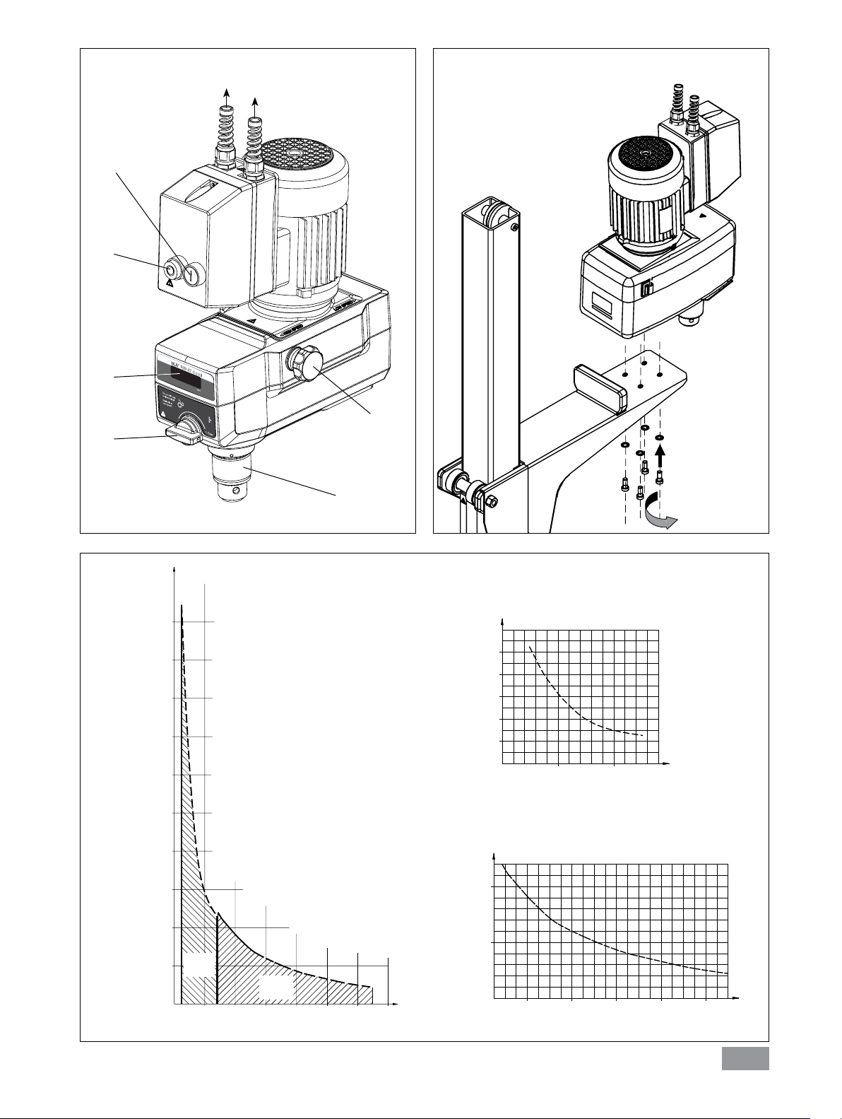
Neglecting all losses, the power at the output shaft
during power transmission (conversion) is always as
great as the power output of the motor. The gear
train merely provides rpm and torque conversion,
which can be described in purely theoretical terms
by the characteristic curve plotted in Fig. 2.
Friction wheel wear is kept low by a helical clutch
matched to the gear train. The down-pressure required at the friction wheel is adjusted by the helical
clutch according to the moment acting on the stirrer
shaft. A low torque results in a low down-pressure;
a high torque results in a high down pressure.
9
Page 10

Motor circuit breaker
The ball race three-phase motor is maintenancefree. Its attached switching unit features a special
safety device for operation in the case of overcurrent and under-voltage (under-voltage release)
to permanently disconnect the motor and avoid
thermal damage. The instrument can only be
started up again by activating the ON switch (A,
see Fig. 1), when power permitted for the motor
is supplied.
You can nd the basic connection and rating for
the motor on its rating plate.
Gear speed change
You can select one between two gear positions (I
and II) using the toggle button (E, see Fig. 1) on
the front of the instrument. You can only switch
to a different cog wheel gear level when the instrument is switched off (motor stopped).
Output shaft
The safety switch SI 400 can also be connected
to the motor switching unit. When used in combination with an
switch on the instrument only at a defined height
in the stand’s working range.
If the stirring unit is operated in such a way that
the instrument’s OFF switch (B, see Fig. 1) is not
accessible, you must add another EMERGENCY
STOP switch to the work area so that it can be
easily reached.
Otherwise this may cause damage to the gear
cogs. The arrow on the front foil indicates the direction of the chuck.
WARNING
IKA® stand, this allows the user to
Only change the gear position at standstill!
The clamping chuck and output shaft permit clamping IKA® recommend stirrer tools (see “Permitted
IKA® Stirrer tools“ section).
Speed display
The rotation speed is adjusted by means of the
rotary knob (C, see Fig. 1) on the side of the overhead stirrer.
Commissioning
The overhead stirrer RW 47 digital must be secured to a stable stand (e.g. R 474 or R 472) with
four screws and wired according to the wiring diagram for proper use. The stirring vessel must al-
ways be well secured for safety reasons. You must
also ensure that the mounting equipment (e.g.
floor stand, telescope stand) is set up in such a
way that it is not liable to topple and does not start
to move during the stirring procedure. Accessories
must be assembled and wired according to the assembly instructions (Fig. 3 to Fig. 7).
The output shaft is not de
DANGER
The rotation speed is displayed directly in revolutions
per minute (rpm) on the display (D,
If the stirring unit is operated in such a way that the
instrument’s OFF switch (B, see Fig. 1) is not accessible, you must add an another EMERGENCY
STOP switch to the work area so that it can be
easily reached.
signed as a hollow shaft.
Please see section “Safety
instructions“!
see Fig. 1
).
10
Page 11

If above conditions are
met, the instrument is
ready for operation after
plugging in the mains plug.
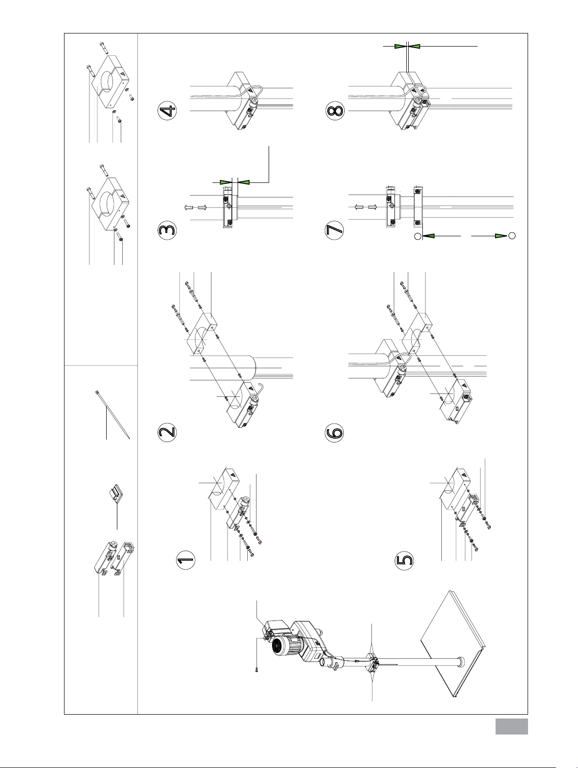
Securing
Points of particular danger (such as crushing, rotating parts, clamping screws for stand legs and rollers etc.) are marked in Fig. 8 with an exclamation
mark. Please pay particular attention to these danger
points during operation!
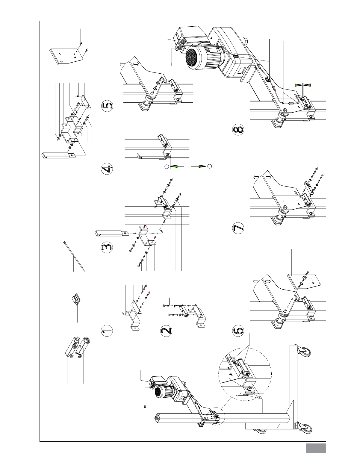
Securing the overhead stirrer to the stand
Diagram (see Fig. 3)
Place RW 47 digital overhead stirrer on the arm of
the stand. Fasten the overhead stirrer to the stand
from below with hexagonal socket screws supplied.
The help of an assistant is needed for screwing on
the overhead stirrer. The cable clips included in the
delivery package are required for fixing the power
cable of the unit (see Fig. 6 and Fig. 7).
Check that the stirrer is held in position firmly prior to
each use and also at regular intervals. The position of
the stirrer must only be adjusted when the equipment
is stationary and the power supply is disconnected.
Securing the stirring element using the chuck
Diagram (see Fig. 4)
Slide the stirring element (I) into the chuck (H).
Tighten the chuck firmly using the chuck key (G).
The stirring tool must only be changed when the
equipment is stationary and the power supply is
disconnected.
Securing the stirring shaft protector
Diagram (see Fig. 5)
You must use stirring shaft protector (K), e.g. R 301,
when working to prevent injury. Use the bolts (J) to
attach the plastic half-shell pieces to the stirrer (M),
as shown in Fig. 5. The screw (L) can be used to
adjust the length of the stirring shaft protector.
Check that the stirring shaft protector is held in position securely prior to each use and also at regular
intervals. The position of the stirring shaft protector
must only be adjusted when the equipment is stationary and the power supply is disconnected.
Securing the safety switch to R 472 floor stand
Diagram (see Fig. 6)
There is a danger of trapping between the
safety limit switch, switch contacts and the
end stop!
Secure the safety switch SI 400 safety switch to
the support rod of R 472 floor stand via fixing device SI 472. For this, follow the assembly instructions for “Safety switch” in the Fig. 6.
Securing the safety switch to R 474 telescopic stand
Diagram (see Fig. 7)
There is a danger of trapping between the
safety limit switch, switch contacts and the
end stop!
Mount the safety switch SI 400 safety switch to
the support rod of R 474 telescopic stand via fixing device SI 474. For this, follow the assembly
instructions for “Safety switch” in the Fig. 7.
Switching on the instrument
Check whether the voltage given on the type plate
corresponds to the available mains voltage.
The socket used must be
earthed (fitted with earth
contact).
If these conditions have been met
ready to operate when the mains plug is plugged in.
If these conditions are not met, safe operation is not
guaranteed and the machine could be damaged.
When working with safety switch SI 400, the instrument only starts up once it has been set to the
designated working height and the switch contact
activates the safety switch.
, the machine is
11
Page 12

During commissioning of the machine the output
shaft starts to run at the speed setting in last operation. Therefore check the setting of the control
knob (speed). Also ensure that the speed set is
suitable for the test medium selected. If you are unsure, set the motor slide to the lowest speed (front
motor slide stop) using the rotary control knob (C)
on the side and the gear to the lowest level.
Maintenance and cleaning
The instrument will start up when you press the
ON switch (A) on the motor.
If the unit has not been used for some time, a
knocking noise will be heard when switching on,
which is due to the preload on the friction lining
of the friction wheel drive. This has no detrimental
effect on the function of the unit, and the knocking
noise will disappear after a short running-in period.
The equipment is maintenance-free. It is only
subject to the natural wear and tear of components and their statistical failure rate.
Cleaning
DANGER
Use only cleaning agents which have been approved by
Dirt Cleaning agent
Dye isopropyl alcohol
Construction
material
Cosmetics
Foodstuff
Fuel
For materials which are not listed, please request
information from
Wear protective gloves during cleaning the devices.
Electrical devices may not be placed in the cleansing
agent for the purpose of cleaning.
Do not allow moisture to get into the equipment
when cleaning.
IKA® to clean the instruments.
For cleaning unplug the
equipment!
water containing tenside/
isopropyl alcohol
water containing tenside/
isopropyl alcohol
water containing tenside
water containing tenside
IKA® application support.
When cleaning the unit, take particular care not to
bring substances containing oil or grease into contact with the running surfaces of the cone pulley and
the friction wheel. This would substantially reduce
the frictional coecient resulting from the pairing
of the friction wheel and cone pulley materials, and
would impair power transmission in the unit.
Spare parts order
When ordering spare parts, please give:
- machine type
- manufacturing number, see type plate
- item and designation of the spare part see
www.ika.com, spare parts diagram and spare
parts list
- software version.
Repair
Please send in equipment for repair only
after it has been cleaned and is free from
any materials which may constitute a health
hazard.
For repair, please request the “Decontamination
Certificate” form IKA® or use the download
printout of it from IKA® website: www.ika.com.
If you require servicing, return the equipment in its
original packaging. Storage packaging is not sucient. Please also use suitable transport packaging.
Before using another than the recommended
method for cleaning or decontamination, the user
must ascertain with
not destroy the instrument.
IKA® that this method does
12
Page 13

Error codes
The fault is shown by an error code on the display (D) as following if the error occurs, e.g. Er 4.
Proceed as follows in such cases:
F Switch the device switch (B) off.
F Remove the stirrer tool and remove the instrument from the assembly.
F Reduce the speed and switch on (instrument switch (A)) the device without the stirrer tool.
Error code Cause Effect Solution
Er 8
If the actions described fails to resolve the fault or another error code is displayed then take one of the
following steps:
- Contact the service department
- Send the instrument for repair, including a short description of the fault.
Speed sensor fault or overload
motor off Switch off the instrument
Warranty
In accordance with
warranty period is 24 months. For claims under
the warranty please contact your local dealer. You
may also send the machine direct to our factory,
enclosing the delivery invoice and giving reasons
for the claim. You will be liable for freight costs.
IKA® warranty conditions, the
Accessories
R 472 Floor stand
R 474 Telescopic stand
R 301 Stirring shaft protection
R 301.1 Support holder
Permitted IKA® stirrer tools
R 1345 Propeller stirrer
R 2302 Propeller stirrer
R 1385 Propeller stirrer
R 1388 Propeller stirrer
R 1302 Dissolver stirrer
Max. Speed rpm
≤
800
≤
600
≤
800
≤
400
≤
1000
The warranty does not cover worn out parts, nor
does it apply to faults resulting from improper use,
insucient care or maintenance not carried out in
accordance with the instructions in this operating
manual.
SI 400 Safety switch
SI 472 Fixing device
SI 474 Fixing device
Max. Speed rpm
R 1355
R 1376
R 2311
R 1333
Centrifugal stirrer ≤ 800
Paddle stirrer ≤ 800
Paddle stirrer ≤ 600
Anchor stirrer ≤ 800
13
Page 14

Technical data
Speed range
Speed adjustment Stepless
Speed display
Speed setting accuracy
Deviation of speed measurement
Max. torque stirrer shaft Ncm
Maximum stirring quantity (water) ltr 200
Max. viscosity mPas 100000
Permitted on-time % 100
Nominal voltage VAC 3 x 400 Y 3 x 230 ∆ 3 x 400 Y 3 x 230 ∆
Frequence Hz 50 50 60 60
Motor speed rpm 2880 2850 3425 3425
Motor input power W 554 548 489 490
Motor output power W 370 370 370 370
Maximum output at stirrer shaft W 300 300 300 300
Protection type to DIN EN 60529 IP 54
Protection class I (protective earth)
Exess voltage category II
Contamination level 2
Protection at overloaded Yes / overcurrent and undervoltage switch on the
Fuse (adjustable) A 1 1,75 0,86 1,5
Perm. ambient temperature °C + 5 to + 40
Perm. ambient humidity (rel.) % 80
Drive
Clamping chuck – clamping range mm
Housing
Dimension (W x D x H) mm 145 x 465 x 358
Weight (with clamping chuck) kg 16
Operation at a terrestrial altitude m max. 2000 above sea level
(50Hz stage I)
(50Hz stage II)
(60Hz stage I)
(60Hz stage II)
rpm 57 – 275
275 – 1300
69 – 330
330 – 1560
Didplsy (LED)
rpm
rpm
± 1
± 10
4642 (with 57 rpm)
3000 (with 100 rpm)
285 (with 1000 rpm )
three-phase motor
Rib cooled three-phase motor with friction wheel
drive and subsequent 2-stage toothed gear train
3
–
16
Coated aluminium casting and thermoplastic plastic
Sbuject to technical changes!
14
Page 15

Verdrahtungsplan / wiring diagram:
3x 230V / 50/60Hz
H
LRD 06
LRD 06
LRD 06
LRD 06
LRD 06
Nicht im Lieferumfang /
Not included in delivery
Sicherheitsschalter/
Safety switch
BU
BN
Nicht im Lieferumfang/
Not included in delivery
Netzkabel/
Mains cabel
L1 L2 L3
GNYE
TEST
0
H
TEST
0
H
TEST
0
TEST
0
A
I
0
A
Einstellung (Strom [A]) des Relais/
Overload (current [A]) adjustment
I
I
Gerätevariante/
device variant
RW47 digital
3x230V / 50Hz
RW47 digital
3x230V / 60Hz
Auslösesimulation/
Trip test
S09
S10
9596
I
Position Rückstellung Hand (H) - Auto (A)/
manuel (H) - auto RESET
IKA-Lieferzustand : Auto (A)
IKA-delivery status : Auto (A)
I
click
R E S E T
S T O P
Funktion Stop/
Stop function
95
96
Stromwert(einstellen)/
current (adjust)
1.75A
1.5A
A1
A2
RD
RD
1 L1
Schütz /
Contactor
14 NO
2 T1
LRD 06
0
A
98 NO
97 NO
4 T2
2 T1
Motorschutz-Relais/
Motor protection relay
WH
L1
L2
U1
U2
RD
3 L2
5 L3
21 NC
22 NC
4 T2 6 T3
R E S E T
I
S T O P
96 NC
95 NC
6 T3
BN
L3
V2 W2
YE BK
RD
A113 NO
RD
RD
A2
RD
RD
f
GY
W1V1
GNYE
Motor / motor
(Dreieckschaltung)
(delta-connection)
GNYE
BU
Power PCB
BU
BU
Hall Sensor PCB
RD
WH
BK
GND
WH
+5v
RD
LED Display PCB
RD
Wire Twisted
WH
RD
WH
BK
Litzenkennzeichnung nach IEC 60757/
Stranded conductor colour coding to IEC 60757
15
Page 16

Verdrahtungsplan / wiring diagram:
3x 400V / 50/60Hz
H
LRD 06
LRD 06
LRD 06
LRD 06
LRD 06
Nicht im Lieferumfang /
Not included in delivery
Sicherheitsschalter/
Safety switch
BU
BN
Nicht im Lieferumfang/
Not included in delivery
Netzkabel/
Mains cabel
L1 L2 L3 N
GNYE
TEST
0
H
TEST
0
H
TEST
0
TEST
0
A
I
0
A
Einstellung (Strom [A]) des Relais/
Overload (current [A]) adjustment
I
I
Gerätevariante/
device Variant
RW47 digital
3x400V / 50Hz
RW47 digital
3x400V / 60Hz
Auslösesimulation/
Trip test
S00
S03
S01
Stromwert(einstellen)/
current (adjust)
9596
I
Position Rückstellung Hand (H) - Auto (A)/
manuel (H) - auto RESET
IKA-Lieferzustand : Auto (A)
IKA-delivery status : Auto (A)
I
click
R E S E T
S T O P
Funktion Stop/
Stop function
95
96
1.00A
1.00A
0.86A
BU
RD
1 L1
5 L3
LRD 06
97 NO
14 NO
2 T1
2 T1
WH
L1
U1
3 L2
21 NC
13 NO A1
A2
22 NC
6 T3
4 T2
R E S E T
I
0
A
S T O P
96 NC
98 NO
95 NC
6 T3
4 T2
GY
BN
L2 L3
V1
W1
RD
RD
f
d
Schütz /
Contactor
Motorschutz-Relais/
Motor protection relay
A1
A2
GNYE
Motor / motor
Sternschaltung/
YEV2BK
W2
star-connection
U2
RD
RD
BU
BU
GNYE
RD
RD
Power PCB
BU
BU
Hall Sensor PCB
RD
WH
BK
WH
GND
+5v
RD
RD
WH
LED Display PCB
WH
BK
RD
Wire Twisted
Litzenkennzeichnung nach IEC 60757/
Stranded conductor colour coding to IEC 60757
Klemmleiste/
Connector block
16
Page 17

®
IKA
- Werke GmbH & Co.KG
Janke & Kunkel-Str. 10
D-79219 Staufen
Tel. +49 7633 831-0
Fax +49 7633 831-98
sales@ika.de
www.ika.com
 Loading...