

Page 1

HOME THEATRE RACK SYSTEM
USER’S MANUAL
HAV-R400G
HAV-R500G
HAV-R500GHAV-R400G
To prevent damage or injury, be sure to read and understand these User’s Manual before assembling or using
your IGO Audio HOME THEATRE RACK SYSTEM.
Please keep these instructions handy for future reference.
650-AVR500-01
Page 2

2
Important Safety Instructions
1. Read these instructions.
2. Keep these instructions.
3. Heed all warnings.
4. Follow all instructions.
5. Do not use this apparatus near water.
6. Clean only with dry cloth.
7. Do not block any ventilation openings. Install in
accordance with the manufacturer’s instructions.
8. Do not install near any heat sources such as radiators,
heat reaisters, stoves, or other apparatus (including
amplifiers) that produce heat.
9. Do not defeat the safety purpose of the polarized or
grounding-type plug. A polarized plug has two blades
with one wider than the other. A grounding type plug
has two blades and a third grounding prong. The wide
blade or the third prong are provided for your safety. If
the provided plug does not fit into your outlet, consult
an electrician for replacement of the obsolete outlet.
10. Protect the power cord from being walked on or
pinched particularly at plugs, convenience receptacles,
and the point where they exit from the apparatus.
11. Only use attachments/accessories specified by the
manufacturer.
12. Use only with the cart, stand, tripod,
bracket, or table specified by the
manufacturer, or sold with the
apparatus. When a cart is used, use
caution when moving the cart/apparatus
combination to avoid injury from tip-over.
13. Unplug this apparatus during lighting storms or when
unused for long periods of time.
14. Refer all servicing to qualified service personnel.
Servicing is required when the apparatus has been
damaged in any way, such as power-supply cord or
plug is damaged, liquid has been spilled or objects
have fallen into the apparatus, the apparatus has been
exposed to rain or moisture, does not operate
normally, or has been dropped.
WARNING : SHOCK HAZARD - DO NOT OPEN.
AVIS : RISQUE DE CHOC ÉLECTRIQUE - NE PAS OUVRIR.
THIS DEVICE COMPLIES WITH PART 15 OF THE FCC RULES.
OPERATION IS SUBJECT TO THE FOLLOWING TWO CONDITIONS;
(1) THIS DEVICE MAY NOT CAUSE HARMFUL INTERFERENCE, AND
(2) THIS DEVICE MUST ACCEPT ANY INTERFERENCE RECEIVED,
INCLUDING INTERFERENCE THAT MAY CAUSE UNDESIRED OPERATION.
THIS CLASS B DIGITAL APPARATUS COMPLIES
WITH CANADIAN ICES-003. CET APPAREIL
NUMÉRIQUE DE LA CLASSE B EST CONFORME
À LA NORME NMB-003 DU CANADA.
FCC Information for use
The following FCC statement applies only to the version of
this model manufactured for sale in the U.S.A. Other
versions may not comply with FCC technical regulation.
CAUTION
You are cautioned that any changes or modifications not
expressly approved in this manual could void your authority to
operate this equipment.
NOTE:
This equipment has been tested and found to comply with the
limits for a Class B digital device, pursuant to Part 15 of the FCC
Rules. These limits are designed to provide reasonable protection
against harmful interference in a residential installation. This
equipment generates, uses, and can radiate radio frequency
energy and, if not installed and used in accordance with the
instructions, may cause harmful interference to radio
communications. However, there is no guarantee that interference
will not occur in a particular installation. If this equipment does
cause harmful interference to radio or television reception, which
can be determined by turning the equipment off and on, the user
is encouraged to try to correct the interference by one or more of
the following measures:
– Change the direction or location of the receiving antenna.
– Increase the separation between the equipment and receiver.
– Connect the equipment into an outlet on a circuit different from
that to which the receiver is connected.
– Consult the dealer or an experienced radio/TV technician for
help.
Page 3
Table of Contents
3
Thank you for purchasing an IGO Audio HOME THEATRE RACK SYSTEM.
Explanation of marks used in these instructions
Explanation of marks used in these instructions
Describes additional explanations on functions, references and
restrictions.
• These operating instructions are common between
HAV-R400G and HAV-R500G. Illustrations used in these
instructions are based on HAV-R400G. Visual appearance
of HAV-R500G is slightly different from the illustrations in
these instructions.
Explains the terms used (some terms are used for a different
meaning in certain fields).
Indicates the page number which contains the relevant
information.
Describes notes on operation.
Describes operating precautions.
Getting Started
Supplied Accessories.................................... 4
Safety Precautions ........................................ 5
Notes and Precautions on Use .................. 10
Important Notice ......................................... 10
Licenses and Trademarks ........................... 10
About this Unit ............................................. 11
Installation
Installing External Equipment such as a
TV and Player ............................................... 14
Connecting the Audio Player ...................... 15
When using Audio Player .......................................... 15
Connecting a TV and Player ....................... 16
Connecting equipment with an HDMI jack (TV, DVD/
BD player, etc.) ...................................................... 16
Connecting equipment without an HDMI jack (TV,
DVD/BD player, etc.) .............................................. 17
Connecting the Power Cord ....................... 18
Preparing the Remote Control ................... 18
Inserting batteries into the remote control ................. 18
Turning on the Power .................................. 19
About the remote control’s operating range .............. 19
Functions
Listening to the TV, DVD or Video Sound ... 20
Selecting the input source ........................................ 20
Adjusting the volume level ........................................ 20
Turning off the sound temporarily (Muting) ................ 20
Selecting the subwoofer level during playback .......... 21
Enjoying Various Sound Modes ................. 21
Selecting the sound mode ........................................ 21
Supported Audio Decode Formats ........................... 22
Advanced Functions and Settings ............. 23
Setting MENU items ................................................. 23
Setting HDMI CEC Link (HDMI SET) ......................... 23
Adjusting delay between picture and sound
(A/V SYNC)............................................................ 24
Enjoying Dolby Digital sound at a low volume
(AUDIO DRC) ......................................................... 24
Adjusting brightness of display panel (DISPLAY) ....... 25
Adjusting level of center speaker/subwoofer
(SP.SET) ................................................................ 25
Setting Dolby Virtual Speaker (DOLBY VS) ................ 26
Setting 2-channel surround mode (2CH SURR) ........ 26
About the HDMI CEC Link .......................... 27
About the HDMI link function .................................... 27
What you can do with HDMI CEC ............................. 27
Troubleshooting
Check the Following First ........................... 28
These do not Constitute a Malfunction ..... 28
Find Solution according to the
Symptoms .................................................... 28
Resetting the theatre rack in the event of
freeze-up .............................................................. 28
Operation ................................................................. 29
Sound ...................................................................... 29
HDMI related problems ............................................. 30
When an Error Message is Displayed ........ 31
Others
Glossary ....................................................... 32
Specifications .............................................. 34
Index ............................................................. 35
Page 4
4
Getting Started
Supplied Accessories
The following accessories are supplied with your IGO Audio HOME THEATRE RACK SYSTEM. Please make sure that
these accessories are included in the package.
If you wish to use an HDMI cable or an optical cable other than those supplied, purchase a commercially-available cable
suitable for the location, jack type and usage environment of the unit.
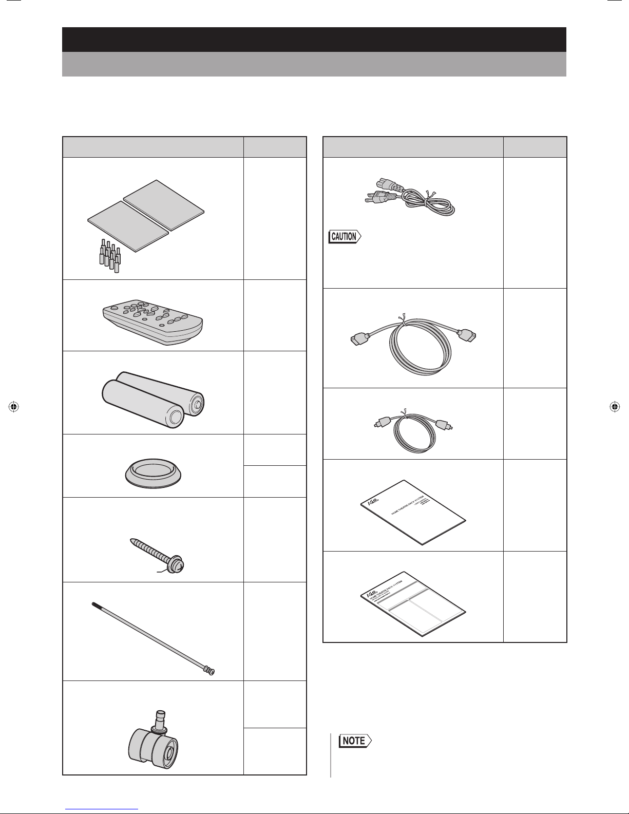
Accessory Quantity
Shelf board
2
Support pin for installing the
shelf boards × 8
Remote control (IRT-S500)
1
AAA R03 batteries
2
Caster tray
HAV-R400G
2
HAV-R500G
4
Topple-prevention screw
For securing the TV to the stand to prevent
the TV from toppling
1
M4 × 16
Long bolt
3
Caster
HAV-R400G
5
HAV-R500G
8
Accessory Quantity
Power cord
1
• Do not use any power cord other than the one
supplied with this unit.
Do not use this power cord for any device other
than this unit.
HDMI cable
1
Optical cable
1
User’s Manual
1
Installation Guide
1
• This package also contains the parts you need to assemble this
unit.
Please refer to the “Installation Guide” (supplied) for details.
Page 5
Getting Started
5
Safety Precautions
Important precautions are provided on the product and in these operating instructions to prevent potential personal injury
to users and other people as well as damage to property, and to ensure the safe and proper use of the product.
Understand the indications, marks and symbols fully before reading the rest of the instructions. Observe the precautions.
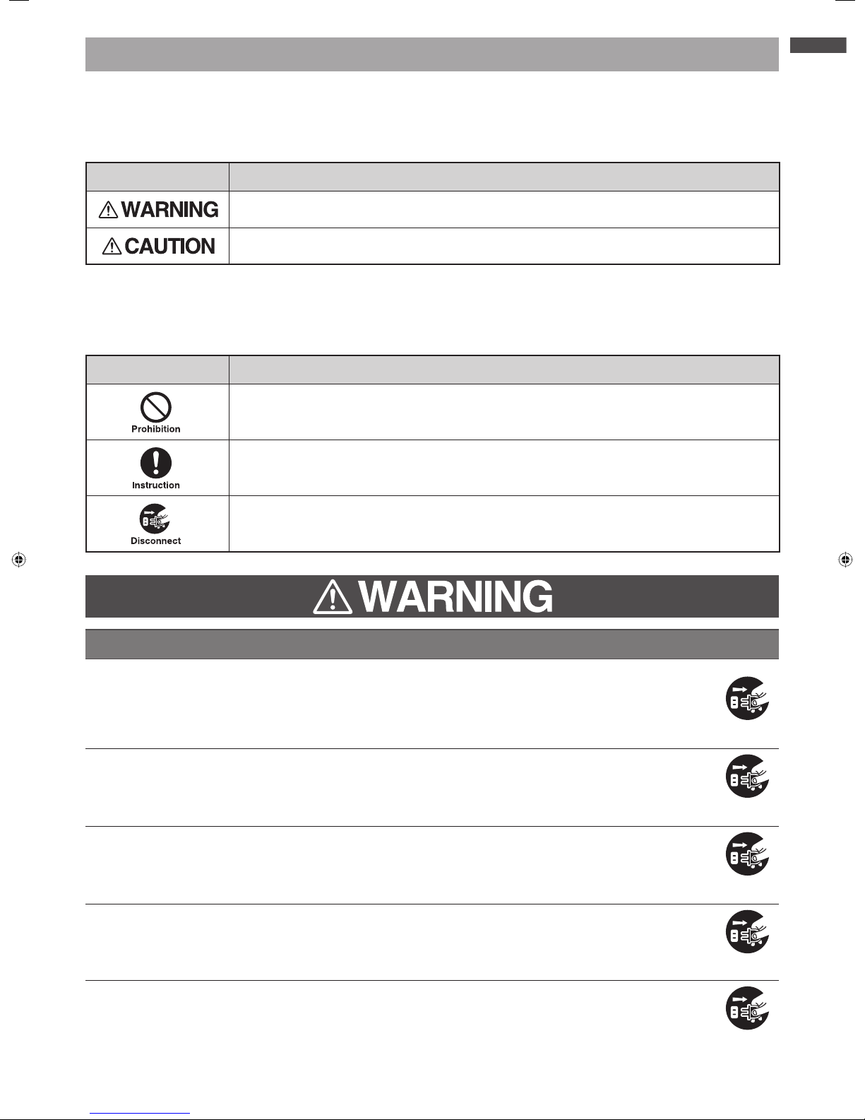
Explanation of Indications
Indication Meaning
Indicates improper handling or operation could result in death or serious injury
1
.
Indicates improper handling or operation could result in minor injury
2
or damage
3
to property.
1: Serious injury refers to loss of sight, injuries, burns (high- and low-temperature), electric shock, broken bones and poisoning, etc. that cause
after-effects or require hospitalization or prolonged outpatient treatment.
2: Minor injury refers to injuries, burns and electric shock that require no hospitalization or prolonged outpatient treatment.
3: Damage to property refers to extended damage to houses, buildings, furniture, livestock, pets and others.
Explanation of Symbols
Symbol Meaning
Indicates prohibition (an action that is not allowed).
What is prohibited will be described in or near the symbol in either text or picture form.
Indicates an instruction that must be followed (a compulsory action).
Detailed instructions will be described in or near the symbol in either text or picture form.
Indicates disconnection.
On abnormal operation and breakdown
If the unit emits smoke or an unusual smell, disconnect the power plug from the wall
outlet immediately.
Using the unit under such conditions may result in fire or electric shock.
Make sure that the unit no longer emits the smoke and then contact your dealer.
If the unit produces no sound, disconnect the power plug from the wall outlet
immediately.
Using the unit under such a condition may result in fire.
Contact your dealer for inspection.
If water or other foreign objects enter the unit, disconnect the power plug from the
wall outlet immediately.
Using the unit under such conditions may result in fire or electric shock.
Contact your dealer for inspection.
If the cabinet is damaged, disconnect the power plug from the wall outlet immediately.
Using the unit under such a condition may result in fire or electric shock.
Handling the unit with damaged cabinet may cause injury.
Contact your dealer for inspection or repair.
If the power cord or plug is damaged or becomes hot, press the POWER button on
the unit to turn it off. Make sure that the power plug is cooled down and then
disconnect from the wall outlet.
Using the unit under such conditions may result in fire or electric shock.
If the power cord or plug is damaged, contact your dealer for replacement.
continued
Page 6
6
On installation
Install this unit where the power plug is easily accessible in case of unforeseen
problems or breakdown or when you are not going to use the unit for a long time.
Do not install this unit in a place subject to water splashes such as the bathroom or
outdoors. This may cause fi re or electric shock.
Do not install this unit in an uneven location such as an inclined surface.
The TV may fall and cause injury.
Install the unit on a level, stable surface.
Do not install this unit in a location subject to vibration.
The unit may move or fall, resulting in injury.
Fully insert the power plug into an AC120V wall outlet.
Use of any outlet other than AC120V may result in fire or electric shock.
Improper plug connections may cause the unit to overheat and result in fire.
Avoid using a damaged power plug or a loose wall outlet.
Do not place any objects or pets on the unit.
Metals, liquids, cosmetics and pets may cause fire or electric shock if they enter the unit.
A heavy object placed on the unit may cause injury if it falls.
If the installed TV is wider than this unit, be careful not to allow any protruding portion
of the TV to come into contact with other objects.
The TV may fall or be damaged, resulting in injury.
On operation
Do not repair, modify or disassemble the unit.
High-voltage components inside the unit may cause electric shock or fire.
Contact your dealer for internal inspection, adjustment or repair.
Do not:
damage, modify (e.g. use an extension), heat (place close to any heating appliance)
the power cord or plug;
pull, pinch or place heavy objects on the power cord or plug; or
forcedly bend, twist or bundle the power cord or plug.
Doing so may cause fire or electric shock.
Do not put foreign objects into the unit.
If metals or flammable objects such as papers enter the unit from the ventilation hole, fire or electric
shock may result.
Do not touch the power cord of the unit or the cables/cords of the components
connected to this unit during a lightning storm.
Doing so may cause electric shock.
On cleaning
Disconnect and inspect the power plug occasionally. Clean the dirt and dust
accumulated on the blades and the surface on which the blades are installed.
Failure to observe this warning may cause the insulation to deteriorate, resulting in fire.
Page 7
7
Getting Started
On installation
Do not install this unit in a place subject to high temperature.
Installing the unit in a place subject to high temperature, such as a location near a heater may cause fire.
It may also deform or damage the cabinet, resulting in electric shock.
Do no install this unit in a place subject to humidity, oil mist or high levels of dust.
Installing the unit near a humidifier or cooking stove or in a dusty place may cause fire or electric shock.
If no measure is taken to prevent the TV from falling or toppling, there may be a high
risk of injury.
Refer to on preventing the TV from falling or toppling.
Do not block the ventilation holes.
Blocked ventilation holes may cause heat build-up and result in fire.
The gap created around the amplifier is there to dissipate its heat emissions. Do not place objects on
the amplifier or block the gap.
Do not push the unit against the wall. (Allow a gap of approximately 4 inches between the unit and
the wall.)
Do not push the unit into a place with poor ventilation, such as a closet.
Do not place the unit with its front side facing up, on its side or upside down.
Do not place any equipment exceeding the specifi ed maximum weight on the top,
shelf or bottom board of the unit.
Prolonged use of the unit with overweight objects placed on it may cause injury or damage to the unit.
For both HAV-R400G and HAV-R500G, the weight limits for the objects to be placed on each board.
Refer to Specifications
.
Do not place any objects other than a TV on the top board.
To move or carry this unit:
When moving the unit, disconnect the unit’s power plug, and any cables and wires
connected to the unit and topple-prevention device.
Moving the unit without disconnecting these components may cause fire or electric shock from a
damaged power cord or injury due the TV toppling from the top of the unit.
Handle with care to avoid impact.
Failure to observe this caution could result in damage to the unit and injury.
Do not put your foot in the gap between the bottom board and floor surface.
Failure to observe this caution could result in injury.
Remove TV from unit before moving.
TV could topple and cause serious injury or damage.
If the unit becomes unstable, retighten the three screws used during installation.
For details, refer to “Installation Guide” (supplied).
If you keep using the unit when the screws are loose, the TV may topple over and cause injury.
Do not lubricate the casters.
Lubrication may crack or damage the casters, resulting in damage or injury due to a fallen unit or TV.
On operation
When installing a TV:
Take measures to prevent falling.
Failure to observe this caution may cause the TV to fall, resulting in injury or damage. Be extra careful
with children.
Refer to on preventing the TV from falling or toppling.
continued
Page 8
8
Do not exceed the maximum rated output power when using a wall outlet or wiring
device.
Avoid sharing a single outlet with an unreasonable number of other devices.
Doing so may cause fire or electric shock.
Do not pull the power cord to disconnect the power plug.
Pulling the power cord to disconnect the power plug from the wall outlet may cause damage to the
power cord or plug, resulting in fire or electrical shock.
Grasp the power plug to disconnect it.
Avoid plugging or unplugging the power plug with wet hands.
Doing so may cause electric shock.
Do not hang or climb on this unit or TV; and do not use this unit as a step ladder.
Doing so may damage the unit or TV or cause it to fall or topple, resulting in injury.
Be extra careful with children.
If you are not going to use the unit for a long time (e.g. if you are travelling) be sure to
disconnect the power plug from the wall outlet for safety.
If the power plug is not disconnected, fire may result in the event of breakdown.
The unit is not completely disconnected from the power source even if the TV monitor is turned off by
pressing the POWER button on the TV or remote control.
To completely disconnect this unit from the power source, disconnect the power plug from the wall
outlet.
Avoid prolonged listening to the audio at high volume levels.
Listening to sound at such a high volume that it irritates ears may damage your hearing.
Do not allow rubber or plastic/vinyl products to come into prolonged contact with the
unit.
This may cause deterioration or damage to the surface finishing.
Do not place objects that are easily infl uenced by magnetism, such as clocks, on this
unit.
This may cause these objects to stop working.
Do not hit or apply impact to this unit.
The top glass panel may break and cause injury.
It may also cause damage to the speakers.
Do not place hot objects such as a heated pan or kettle on the unit.
The top glass plate may break and cause injury or damage to the unit.
Batteries used for the remote control:
Do not use any batteries other than those specified.
Follow the polarity markings inside the compartment.
Do not charge, heat, disassemble or short-circuit the batteries.
Do not expose the batteries to excessive heat such as fire or direct sunlight.
Do not leave expired or drained batteries inside the remote control.
Do not use different types of batteries or a new battery with an old one at the same
time.
Failure to observe these cautions may result in burns or injury due to battery leakage or explosion.
Leaked battery fluid may harm your eyes or skin. If it gets in contact with your eyes or skin, flush the
affected area with clean water and seek medical attention immediately.
If battery fluid comes in contact with clothing, flush the affected area with clean water immediately.
If battery fluid has spilled on the apparatus, wipe it off avoiding direct contact.
Page 9

9
Getting Started
On cleaning
Disconnect the power plug from the wall outlet before cleaning the unit.
Failure to observe this caution may cause electric shock.
Do not use benzene or alcohol.
Do not use any volatile solvents such as benzene or alcohol. Use of such substances may cause the cabinet to
deteriorate or damage the surface finishing.
Cleaning the cabinet and control panel.
Remove the dirt and dust accumulated on the cabinet and then lightly wipe with a commercially-available cleaning
cloth or soft cloth. Wiping or rubbing the cabinet or control panel with a dirty cloth or an abrasive cloth may
damage or scratch the glass panel or cabinet surface.
When using a chemical cleaning cloth, follow the instructions on the package.
Page 10
10
Notes and Precautions on Use
On operation
Be careful that some parts of this unit may become hot
during use.
If you move the unit to a remote place (e.g. moving
house) cover it with an object such as a blanket to avoid
damage. Do not subject the unit to strong impact or
vibration.
Do not spray volatile solvents such as insecticides.
Do not allow rubber or plastic/vinyl products to come
into prolonged contact with the unit. This may cause
deterioration or damage to the surface finishing.
Avoid placing magnetic cards such as ATM cards or
video tapes near the unit. Data or information stored
inside may be lost due to magnetism from the unit.
External input images or sound may be slightly delayed
causing discomfort to users;
• when enjoying Karaoke using a Karaoke equipment
connected to the unit; or
• when listening to the sound from a DVD or video
directly connected to the unit.
On disposal
Dispose of this product following the local guidelines or
regulations for its disposal. Contact your local
government for more detailed information on disposal.
Disclaimer
FORMOSA PROSONIC INDUSTRIES BERHAD shall not
be liable for any damages arising out of or in connection
with a natural disaster such as an earthquake or
lightning, fire, act of any third party, other accidents,
intentional or negligent act of customer, misuse and/or
use of this product under other abnormal conditions.
FORMOSA PROSONIC INDUSTRIES BERHAD shall not
be liable for any incidental damages arising out of or in
connection with the use or unavailability of this product
(including damages to business interests, business
interruption and loss of viewing fees).
FORMOSA PROSONIC INDUSTRIES BERHAD shall not
be liable for any damages arising out of or in connection
with non-observance of the contents of these Operating
Instructions.
FORMOSA PROSONIC INDUSTRIES BERHAD shall not
be liable for compensation for and/or incidental damages
arising out of or in connection with any data, including
videos, pictures and sound, that failed to be recorded
correctly in the recording device connected to this unit,
or that were altered or lost.
FORMOSA PROSONIC INDUSTRIES BERHAD shall not
be liable for any damages arising out of or in connection
with malfunctions, defects or improper operations
(including breakdown of the recording device connected
to the unit and alteration or loss of recorded data) occurred
by adding other equipment connected to the unit.
The settings stored in the unit may be altered or lost due
to malfunction or noise including static electricity.
FORMOSA PROSONIC INDUSTRIES BERHAD shall not
be liable for such an incidence.
Important Notice
HDMI link function
HDMI link function
When equipment other than those recommended are
connected to an HDMI input jack of this unit, the unit
may recognize the equipment as an HDMI linked device
and some linked operations
may be available.
However, FORMOSA PROSONIC INDUSTRIES BERHAD
shall not guarantee such linked operations.
Licenses and Trademarks
This product is manufactured under license from Dolby
Laboratories.
Dolby, Pro Logic, the double-D symbol and the AAC logo
are trademarks of Dolby Laboratories.
“HDMI, the HDMI Logo, and High-Definition Multimedia
Interface are trademarks or registered trademarks of HDMI
Licensing LLC in the United States and other countries.”
DTS, DTS-HD, the Symbol, & DTS or DTS-HD and the
Symbol together are registered trademarks of DTS, Inc. ©
DTS, Inc. All Rights Reserved.
Manufactured under license under U.S. Patent Nos:
5,956,674; 5,974,380; 6,226,616; 6,487,535; 7,212,872;
7,333,929; 7,392,195; 7,272,567 & other U.S. and worldwide
patents issued & pending. DTS-HD, the Symbol, & DTS-HD
and the Symbol together are registered trademarks of DTS,
Inc. Product includes software. © DTS, Inc. All Rights
Reserved.
Page 11
11
Getting Started
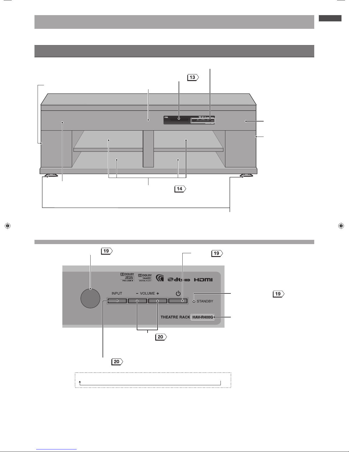
About this Unit
The illustrations below show HAV-R400G. The visual appearance of HAV-R500G is slightly different from the illustrations.
Front view
Display panel
Control panel (see below)
Front speaker (right)
Front speaker (left)
Storage compartments
• You can adjust the height of the shelf
boards (3 levels).
Center speaker
Casters/caster trays (Refer to Installation Guide)
• Be sure to install the supplied caster trays under the
front casters.
Subwoofer (right)
Subwoofer (left)
Control panel
Control panel
TV → HDMI 1 → HDMI 2 → HDMI 3 → OPTICAL → AUDIO 1 → AUDIO 2
Remote sensor
POWER
• Press to turn the power ON and OFF.
INPUT selector
• Each time you press the button, the input source changes as follows:
VOLUME +/–
• Press to adjust the volume level.
POWER indicator
Model indication
continued
Page 12

12
Rear view
Amplifier connections
(see below)
Topple-prevention screw hole
• Use this hole to secure the TV stand to the
unit to prevent toppling.
Amplifier connections
Amplifier connections
The amplifier is fixed to the rack. Do not attempt to remove it.
HDMI output jack
• Use this jack to connect a TV with an HDMI input jack.
Power inlet
• Use this inlet to connect the supplied power
cord.
• When connecting external equipment such as
a TV or BD/DVD player, connect the power
cord to the wall outlet only after the necessary
connections have been completed.
HDMI input jacks 1, 2 & 3
• Use these jacks to connect a BD/DVD player
with an HDMI output jack.
Air-cooling fan
• The unit has a built-in air-cooling fan for heat
dissipation.
• Be careful not to block the fan (ventilation holes).
Speaker jacks
• The speaker jacks are exclusively for the speakers
of this unit. Do not connect any other speakers.
• The speakers are pre-connected to the speaker
jacks. Do not touch the connectors unless
necessary for reconnection, etc.
Optical digital audio input jacks
• “TV” is only for connection to the optical digital
output jack on the TV.
• Use these jacks to connect external equipment
with an optical digital audio output jack.
Analog audio input jacks
• Use these jacks to connect external
equipment with an analog audio output jack.
Page 13

13
Getting Started
Display panel
Input indicator
• Indicates the selected input.
Information display
• Displays the information on the input and status.
Audio signal / decoder indicator
• Indicates the currently played signal and built-in decoder in use.
Muting
Remote control
Buttons on the remote control and their key functions are as described below (some buttons may have different
functions from ordinary operations).
RETURN MENU
AUDIO 1 AUDIO 2 OPTICAL TV
HDMI 1 HDMI 2 HDMI 3
MUTING
IRT-S500
SOUND
MODE
VOLUME
ENTER
SUB
WOOFER
Rear view Front view
Battery compartment
cover
• Remove this cover to
insert batteries.
RETURN
• Press to return to the previous menu.
SUBWOOFER
• Press to adjust the subwoofer level.
Signal transmitter
• To operate the unit, point it at the
remote sensor on the unit.
POWER
• Press to switch “Power ON” and
“Standby”.
INPUT SELECTOR
• Press to select the input source.
(Cursor)
• Press to navigate the items on the MENU.
MENU
• Press to enter the MENU items.
ENTER
• Press to select the items selected on
the MENU.
VOLUME +/–
• Press to adjust the volume level.
MUTING
• Press to mute the sound temporarily.
Press again to restore the sound.
SOUND MODE /
• Press to switch the sound mode.
Page 14

14
Installation
Installing External Equipment such as a TV and Player
Refer to the operating instructions supplied with the installed TV and external equipment. Connect your external
equipment to the unit only after it has been placed on the unit properly. (Refer to “Connecting a TV and Player”
,
on connecting the equipment.)
Place the TV in the center of the unit.
Compatible equipment
Compatible equipment
Storage compartment (right and left)
Model Supported TV size Weight
HAV-R400G Up to 55" 176 lb (80 kg) Max.
HAV-R500G Up to 70" 264 lb (120 kg) Max.
Be sure to place the TV in the
center of the top board of the
unit. For safety, be sure to
take measures to prevent the
TV from falling or toppling
over.
Top glass
Upper compartment
Lower compartment
Model
Equipment
installation
position
Shelf board
installation
position
Storage compartment
(right and left)
Height Depth Width Maximum load
HAV-R400G
Upper
compartment
Upper 3 15/16" (100 mm)
12 3/4"
(325 mm)
17 1/2"
(445 mm)
26 lb (12 kg)Middle 5 1/16" (130 mm)
Lower 6 9/32" (160 mm)
Lower
compartment
Upper 6 7/8" (175 mm)
13 1/2"
(343 mm)
44 lb (20 kg)Middle 5 11/16" (145 mm)
Lower 4 1/2" (115 mm)
HAV-R500G
Upper
compartment
Upper 3 15/16" (100 mm)
12 3/4"
(325 mm)
18 11/16"
(475 mm)
26 lb (12 kg)Middle 5 1/16" (130 mm)
Lower 6 9/32" (160 mm)
Lower
compartment
Upper 6 7/8" (175 mm)
15 11/16"
(398 mm)
44 lb (20 kg)Middle 5 11/16" (145 mm)
Lower 4 1/2" (115 mm)
Height/Depth/Width – Unit: Inch (mm) / Maximum load – Unit: lb (kg)
Ensure good ventilation if the connected equipment’s operating instructions include requirements on heat dissipation or ventilation.
Install the equipment with ventilation holes following the instructions in the equipment’s operating instructions.
Noise may be heard or the image on the TV may be interrupted by electromagnetic radiation emitted by other digital equipment or
microwave ovens. Install the equipment away from such devices.
Page 15

15
Installation
Preventing the TV from falling or toppling
Preventing the TV from falling or toppling
The effectiveness of falling and toppling prevention may decrease significantly depending on the strength of the wall or platform on
which the fall or topple-prevention device is installed. Be sure to provide appropriate reinforcement. The falling and toppling
prevention methods outlined below are intended to reduce the risks such as injuries only, and not to guarantee that these methods
will be effective in all cases.
The unit may fall backwards. After securing the TV, bring the unit closer to the wall so that the unit will not fall backwards.
Infants and children may be injured if allowed behind the unit. Bring the unit closer to the wall so that infants and children cannot go
behind the unit.
The measures described below are only an example of the preventive methods. Other measures should be taken according to the
operating instructions supplied with your TV.
The illustration is an example only. The actual form of the equipment/device differs depending on the connected TV.
Securing the unit and TV stand with topple-prevention belt
Securing the unit and TV stand with topple-prevention belt
Bring the topple-prevention belt located at the bottom of the TV stand to the rear, and use the locking screw (supplied) to securely
fasten it to the topple-prevention screw hole on the back of the unit.
Secure the unit and TV with Topple-prevention
belt (not supplied) and screw M4 × 16 (supplied)
Topple-prevention screw hole
Topple-prevention belt (not supplied)
Stand
TV stand screw (not supplied)
• The TV stand screw and topple-prevention belt are not supplied in this package. For details, please refer to your TV’s User Guide.
Connecting the Audio Player
Cables to be used
Cables to be used
Pin cable (not supplied)
White
Red
White
Red
Pin cable (not supplied)
White
Red
Mini plug
Refer to the operating instructions of each equipment to connect equipment.
When using Audio Player
Amplifier connections
Amplifier connections
Audio Player etc.
To Audio IN
To Audio OUT
Signal
Signal
To Analog Audio OUT
White
Red
White
Red
CD Player
White
Red
• The sound volume may be lower if an audio cable with a built-in resistor is used.
• When the unit is connected to a TV or player with an audio cable, use the remote control of the connected equipment to change the sound
setting for sound multiplex broadcasting programs.
Page 16

16
Connecting a TV and Player
Read the operating instructions of the connected equipment together with these instructions.
Before connecting external equipment, be sure to turn them off and unplug the power cord of the equipment. When
you wish to add any equipment, turn off and unplug the IGO Audio HOME THEATRE RACK SYSTEM as well as the
equipment being installed before proceeding.
Connect the power cord of each piece of equipment only after all the connections have been completed.
Connecting equipment with an HDMI jack (TV, DVD/BD player, etc.)
Connect a HDMI CEC compatible TV with a player as described below. You can operate HDMI CEC compatible TVs
and players using the TV and other remote control via the unit’s link function.
Cables to be used
Cables to be used
HDMI cable
Use the supplied HDMI cable or a commercially-available cable with the HDMI (
) logo. Use a high-speed HDMI cable to
input a 1080p video signal from external equipment (the signal may not be input properly with a standard HDMI cable).
Optical cable
Connect the optical cable as well as an HDMI cable to listen to the sound from a non ARC (Audio Return Channel) compatible TV.
You cannot listen to the TV sound with this unit via an HDMI cable only. Check the jack type of the connected equipment before
purchasing additional cable.
The type of the plug to be connected to the unit is
.
Amplifier connections
Amplifier connections
Connect to one of the
HDMI IN 1 to 3 jacks.
Signal
Signal
HDMI cable (not supplied)
HDMI cable (supplied)
To HDMI OUT
To HDMI
OUT
To HDMI
IN
with an HDMI output jack -
HDMI CEC compatible
Player
TV
with an HDMI output jack -
HDMI CEC compatible
To Optical Digital
Audio OUT
To Optical Digital
Audio IN (TV)
Optical cable (supplied)
Connect the optical cable together with an HDMI cable to listen to the
sound of a
non ARC compatible TV
. You cannot listen to the TV audio
with this unit via an HDMI cable only.
The optical digital audio input jack is
covered. Just insert the plug into the
covered jack after making sure it is
pointing the correct way.
Connect to the Digital Audio IN
(TV).
For connections via an HDMI cable or optical cable
For connections via an HDMI cable or optical cable
Set the digital audio output setting on the connected equipment (such as a TV) to “Auto” or “Bitstream”, etc. Refer to the operating
instructions of the connected equipment for setting method.
• The optical cable may be damaged if it is bent excessively.
About the HDMI PASS-THRU function
• You can listen to the sound of the equipment connected to the unit via the TV speakers even if the unit is in standby mode. If the priority speaker
setting on the TV is set to “AV System” or “Theatre System”, etc., the sound is automatically output from the speakers of the unit when the unit is
turned on.
Page 17

17
Installation
Connecting equipment without an HDMI jack (TV, DVD/BD player, etc.)
Cables to be used
Cables to be used
Pin cable
White
Red
White
Red
Optical cable
Check the jack type of the connected equipment before purchasing additional cable. The type of the plug to be connected to the
unit is
.
Refer to the operating guide of each device for proper connection instructions.
Amplifier connections
Amplifier connections
Optical cable (not supplied)
Use one of these
cables for
connection.
To Optical Digital IN
Pin cable (not supplied)
To Optical Digital Audio OUT
To Analog Audio OUT
To Audio OUT
To Optical Digital
Audio OUT
Optical cable (supplied)To Optical Digital
Audio IN (TV)
Use one of these
cables for
connection.
without an HDMI output jack
Player
TV
Video cord
To Video OUT
To Video IN
The optical digital audio input
jack is covered. Just insert the
plug into the covered jack after
making sure it is pointing the
correct way.
Connect to the Digital Audio
IN (TV).
Signal
Signal
Signal
Signal
White
Red
White
Red
White
Red
White
Red
For connections via an optical cable
For connections via an optical cable
Set the digital audio output setting on the connected equipment (such as a TV) to “Auto” or “Bitstream”, etc. Refer to the operating
instructions of the connected equipment for setup.
• The optical cable may be damaged if it is bent excessively.
• The sound volume may be lower if an audio cable with a built-in resistor is used.
• When the unit is connected to a TV or player with an audio cable, use the remote control of the connected equipment to change the sound
setting for sound multiplex broadcasting programs.
Page 18

18
Preparing the Remote Control
Inserting batteries into the remote
control
Use two R03 or LR03 (size AAA) batteries.
Two R03 (size AAA) batteries are supplied with the unit.
Remove the cover and insert the batteries.
Remove the cover and insert the batteries.
To remove the cover, lift its latch while
pressing it in the direction.
Check the polarity markings + and - to insert the
batteries correctly.
Top of the cover
Bottom of the cover
To close the cover, insert the protrusion at the bottom of
the cover into the notch on the remote control and then
push down the top of the cover until a click is heard.
About batteries
• Battery life differs depending on how the battery is used. Replace
both of two batteries with new ones if you experience difficulty in
using the remote control or if the signal transmission distance
shortens.
• Dispose of the used batteries following your local regulations for
disposal.
Connecting the Power Cord
Be sure to connect the power cords of both the
unit and connected equipment only after all the
connections have been done.
CAUTION!
Do not use the supplied power cord for any
device other than this unit.
The supplied power cord is exclusively for
this product.
Connect the power cord to the amplifier
first, then to the wall outlet.
Connecting to the wall outlet should
be the last connection made.
Power cord
Power cord
(supplied)
(supplied)
Connect the power plug in the above order and . Firmly
insert the power plug fully into an AC120V outlet.
Be sure to power OFF the unit before disconnecting the power
plug.
Page 19

19
Installation
Turning on the Power
After connecting your external equipment, turn on the
power of the unit.
Turning on the power for the first time
Turning on the power for the first time
1
Make sure that the POWER indicator
on the front panel is OFF, then press
on the unit.
The power turns on and the POWER indicator on the
front panel lights up green.
Make sure that the
POWER indicator is OFF.
Press on the front
panel to turn on the power.
The POWER indicator
lights up green (ON).
Turning on the power for the second time
Turning on the power for the second time
onwards
onwards
1
Make sure that the POWER indicator
on the front panel is in standby mode (lit
in red), then press
on the remote
control.
The power turns on and the POWER indicator on the
front panel lights up green.
Make sure that the
POWER indicator is in
standby mode (red).
Press
on the remote
control to turn on the power.
The POWER indicator
lights up green (ON).
If on the remote control is pressed while the power is
turned on, the unit goes into standby mode and the POWER
indicator lights up red.
If
on the unit is pressed, the power is turned off and the
POWER indicator turns off.
The power cannot be turned on by pressing
on the remote
control when the power is OFF (the POWER indicator: OFF).
About the power indicator and display panel
About the power indicator and display panel
The color of the power indicator varies depending on the
power status of the unit. If the brightness of the display panel is
changed
1
, the power indicator also changes accordingly.
Power status
Power
indication
Display
panel
CEC LINK
2
Power OFF (The
power is turned off
using the button on
the unit.)
OFF OFF N/A
Standby (The power
is turned off using the
remote control.)
ON (red) OFF
YES
Power ON
ON (green)
ON
(standard)
ON (green/ dim) ON (dim)
ON (orange) OFF
1 The brightness of the display panel can be set to one of the three levels.
2 Refer to for HDMI CEC Link.
About the remote control’s operating
range
Point the remote control at the remote sensor on the
unit.
Avoid exposing the remote sensor to intense light. The
remote control may not function under such a condition.
Do not place obstacles in the path between the remote
control and remote sensor. Otherwise, the remote
control may not work or will respond slowly.
Remote sensor
Within about 16 ft (5 m)
About 30º About 30º
From the remote sensor:
Distance – Within 16 ft (5 m) / Angle – Within 30˚ (horizontal);
Within 20˚ (vertical)
About the remote control
Do not drop, swing or apply impact to the remote control.
Do not splash water on the remote control or place it on a
wet object.
Do not disassemble the remote control.
Do not place the remote control in a place subject to high
temperature or humidity.
Page 20

20
Functions
Listening to the TV, DVD or Video Sound
AUDIO 1 AUDIO 2 OPTICAL TV
HDMI 1 HDMI 2 HDMI 3
RETURN MENU
IRT-S500
SOUND
MODE
ENTER
SUB
WOOFER
RETURN
MEN
U
RT-S500
UN
D
MODE
ENTER
UB
FER
AUDIO 1 AUDIO 2 OPTICAL TV
HDMI 1 HDMI 2 HDMI 3
MUTING
VOLUME
Selecting the input source
1
Select the input source.
Selecting the input source with the INPUT SELECTOR button
on the front panel.
Select the input source by pressing
button repeatedly.
The input source changes in the following order:
(Actual change of the input source may be slower than the display.)
TV
HDMI 1
HDMI 2
HDMI 3
OPTICAL
AUDIO 1
AUDIO 2
↓
↓
↓
↓
↓
↓
Input sequence Display panel
Selecting the input source with the remote control
Press the INPUT button for the desired source.
Adjusting the volume level
1
Press to control the volume level.
The display appears for about 3 seconds.
Volume control range: 0 (min) – 100 (max)
The volume level is displayed on the front display panel.
The volume level can be controlled by pressing
on the
front panel.
The sound may be interrupted if these buttons are pressed
continuously.
Turning off the sound temporarily (Muting)
About sound etiquette
• When listening to audio, adjust the volume so that you
do not disturb the comfort or relaxation of anyone in
the vicinity or set the mode to “NIGHT” or
“AUDIO DRC” . Especially at night, even a small
sound reaches far and wide. Ensure a comfortable
living environment by caring for each other by taking
measures such as closing windows.
1
Press .
“MUTING” flashes.
“MUTING” is displayed on the front display panel and the “MUTING”
indicator flashes.
Press
again to return to the original volume level.
The mute mode is canceled if you control the volume or turn the unit
off/on.
Page 21

21
Functions
RETURN MENU
AUDIO 1 AUDIO 2 OPTICAL TV
HDMI 1 HDMI 2 HDMI 3
MUTING
IRT-S500
VOLUME
ENTER
SOUND
MODE
DIO 1
DIO 2
PTICA
L
HDMI 1DMI 2
DMI
3
MUTIN
G
RT-S500
VOLUM
E
UN
D
MODE
SUB
WOOFER
Selecting the subwoofer level during playback
You can select one of the three subwoofer levels.
1
Select the desired subwoofer level by pressing
button repeatedly.
The subwoofer level is displayed on the front display panel.
Subwoofer level Display panel
Woofer 1
(Low)
Woofer 3
(High)
Woofer 2
(Medium: Default)
Besides the pre-defined three levels, you may also adjust the
subwoofer level to your liking. For more information, refer to “Adjusting
level of center speaker/subwoofer (SP. SET)”
.
Enjoying Various Sound Modes
RETURN MENU
AUDIO 1 AUDIO 2 OPTICAL TV
HDMI 1 HDMI 2 HDMI 3
MUTING
IRT-S500
VOLUME
ENTER
SUB
WOOFER
ETURN MENU
AUDIO 1AUDIO 2
PTICAL
1
2
3
MUTIN
G
RT-
S500
LUM
E
UB
FER
SOUND
MODE
Selecting the sound mode
You can select a sound mode that suits the genre of the sound to be
played.
The sound mode can be set for each input source
.
1
Select the desired sound mode by pressing .
Each time you press , the sound mode changes as
follows:
STANDARD
CINEMA
DRAMA
NEWS
SPORTS
MUSIC
GAME
JAZZ
CLASSIC
POP
LIVE
NIGHT
continued
Page 22

22
About sound mode
About sound mode
Video/Sound
category
Suitable
sound mode
Effects
All categories STANDARD
You can enjoy the standard sound that suits any type of videos and sounds.
If no information on the category is available for viewing/playing program, set
the sound mode to “STANDARD”.
Movies CINEMA
Produces a powerful and realistic sound, along with clear dialog.
Dramas DRAMA
Suitable for TV dramas.
News NEWS
Produces the announcer’s voice clearly.
Sports SPORTS
Produces clear play-by-play commentary and realistic sound with surround
effects, such as cheering, etc.
Music programs MUSIC
Produces optimal sound for programs or music Blu-ray Discs, DVDs and
CDs.
Suitable for listening to music.
Game equipment GAME
Produces a powerful and realistic sound, suitable for playing video games.
Music programs,
BDs, DVDs and
CDs
JAZZ
Produces sound with emphasized, rich bass and treble. Suitable for jazz
music.
CLASSIC
Produces sound with emphasized bass and treble as well as sharp high
notes. Suitable for classical music.
POP
Delivers light sound suitable for pop music.
LIVE
Delivers the atmosphere of a concert hall.
–––––– NIGHT
Suitable for listening to sound at a low volume late at night. You can enjoy
surround effect and hear the dialog in movies even at a low volume level.
The effect may not be obtained depending on the data to be reproduced (or
category or decoder used).
Supported Audio Decode Formats
Audio formats supported by this system are as follows.
Audio decode
format
Input source
LPCM 2ch
LPCM 5.1ch
LPCM 7.1ch
Dolby
Digital
Dolby
TrueHD
Dolby Digital
Plus
DTS
DTS-HD
Master
Audio
DTS-HD
High
Resolution
Audio
DTS
96/24
AAC
(MEPG2)
HDMI
DIGITAL IN (OPTICAL)
–
–
–––
: Supported format
–: Unsupported format
Decoded multi channel 5.1/7.1-ch signals are outputted from 3.1-ch speakers by re-arrangement.
Page 23

23
Functions
Advanced Functions and Settings
AUDIO 1 AUDIO 2 OPTICAL TV
HDMI 1 HDMI 2 HDMI 3
MUTING
IRT-S500
VOLUME
SUB
WOOFER
SOUND
MODE
AUDIO 1AUDIO 2
PTICAL
3MU
TIN
G
RT-
S500
LUM
E
UB
FER
UND
D
E
RETURN MENU
ENTER
You can change the MENU items to your liking.
Setting MENU items
Pressing
displays “MENU” on the front display panel and enables
you to set the MENU items.
Default settings are shown in bold type.
MENU
HDMI SET LINK ON
LINK OFF
ARC ON
ARC OFF
-6~-3~+6
-6~0~+6
DISPLAY DISP ON
DISP DIM
DISP OFF
SP.SET WOOFER
CENTER
DOLBY VS AUTO
ON
OFF
2CH SURR DOLBY PLII
DTS NEO:6
AUDIO DRC DRC OFF
DRC STD
DRC AUTO
DRC MAX
A/V SYNC SYNC AUTO
SYNC SET
SYNC OFF
10ms~200ms
Setting HDMI CEC Link (HDMI SET)
Sets HDMI CEC Link
function.
To return to the previous menu, press .
1
Press .
2
Press to select “HDMI SET”, then press
.
3
Press to select “LINK ON” or “LINK OFF”,
then press .
LINK ON
Operations of the unit and HDMI CEC compatible equipment will be
linked.
LINK OFF
Operations of the unit and HDMI CEC compatible equipment will not
be linked.
Once the setting is completed, press until the input source such as “TV”
and “HDMI 1” is shown on the display panel to end the menu.
continued
Page 24

24
If the ARC function of the HDMI jack is not
If the ARC function of the HDMI jack is not
in use
in use
If the unit is connected to an ARC compatible TV using
both HDMI and optical cables, priority is given to sound
via the HDMI cable. If you wish to listen to sound via the
optical cable, turn off the ARC function following the
steps below.
Perform the above Steps 1 and 2.
Press to select “LINK ON”,
then press
.
Press to select “ARC OFF”,
then press .
“OPTICAL” lights up.
Adjusting delay between picture and
sound (A/V SYNC)
You can delay the sound using this function when the
picture is slower than the sound.
AV/SYNC can be set for each input jack type.
About input jack type
HDMI IN: HDMI 1, HDMI 2 and HDMI 3
Optical digital IN: TV and Optical Digital
Audio IN: Audio 1 and Audio 2
Individual settings can be made for TV and Optical Digital.
To return to the previous menu, press .
1
Press .
2
Press to select “A/V SYNC”, then
press .
3
Press to select “SYNC AUTO” or
“SYNC SET”, then press .
SYNC AUTO
When the unit is connected to an equipment with the
auto audio delay function via an HDMI cable, the
optimal audio delay is automatically set if “SYNC AUTO”
is selected.
(The mode is set to “OFF” when the unit is connected
to equipment with no auto audio delay function.)
SYNC SET
Select this mode to set the delay time. Move on to Step 4.
4
Press to select “OFF” or delay
time.
If “OFF” is selected, the A/V SYNC function is not
activated.
The setting range is 10ms to 200ms in 10ms
increments.
Once the setting is completed, press
until the input
source such as “TV” and “HDMI 1” is displayed on the display
panel to end the menu.
Enjoying Dolby Digital sound at a low
volume (AUDIO DRC)
Compresses the dynamic range (difference between the
softest and loudest sounds in audio signal) for clearer
dialog even at a low volume level without affecting the
sound field.
This function is useful when you may not listen to the
sound at a high volume late at night.
To return to the previous menu, press .
1
Press .
2
Press to select “AUDIO DRC”,
then press .
3
Press to select the setting item.
DRC OFF
Ordinary playback without compression of dynamic
range.
DRC AUTO
Compresses dynamic range according to the sound
source.
DRC STD
Compresses dynamic range at the standard level.
DRC MAX
Compresses dynamic range fully.
Once the setting is completed, press
until the input
source such as “TV” and “HDMI 1” is displayed on the display
panel to end the menu.
About delay time
• The unit of delay time is ms (millisecond). It is a unit to express time, which is a thousandth (1/1000) of a second.
Page 25

25
Functions
Adjusting brightness of display panel
(DISPLAY)
You can change brightness of display panel.
To return to the previous menu, press
.
1
Press .
2
Press to select “DISPLAY”, then
press
.
3
Press to select the setting item.
DISP ON
Standard brightness
DISP DIM
Dimmer than the standard brightness
DISP OFF
Turns off the display.
Once the setting is completed, press
until the input
source such as “TV” and “HDMI 1” is displayed on the display
panel to end the menu.
Adjusting level of center speaker/
subwoofer (SP.SET)
You can adjust center speaker and subwoofer to your
desired level.
To return to the previous menu, press
.
1
Press .
2
Press to select “SP.SET”, then
press
.
3
Press to select “WOOFER LV” or
“CENTER LV”, then press .
WOOFER LV
Select this to adjust level of subwoofer.
Move on to Step 4 to adjust level.
CENTER LV
Select this to adjust level of center speaker.
Move on to Step 4 to adjust level.
4
Press to adjust level.
The setting range is –6dB to +6dB in 1dB increments
for both the subwoofer and center speaker.
Default setting:
Subwoofer: −3dB
Center speaker: ±0
Once the setting is completed, press
until the input
source such as “TV” and “HDMI 1” is displayed on the display
panel to end the menu.
continued
Page 26

26
Setting Dolby Virtual Speaker (DOLBY
VS)
Dolby Virtual Speaker (“DOLBY VS”) delivers the
surround effect similar to 5.1-channel system.
To return to the previous menu, press
.
1
Press .
2
Press to select “DOLBY VS”, then
press .
3
Press to select the setting item.
AUTO
ON/OFF modes of DOLBY VS automatically changes
as shown below according to the category of sound
mode
and audio signal.
Sound mode category
2-channel
stereo signal
(no surround
information)
2-channel
stereo signal
(with surround
information/
5.1- and other
multi-channel
signal)
STANDARD
NEWS
JAZZ
CLASSIC
POP
OFF
ON
*
1
CINEMA
DRAMA
SPORTS
MUSIC
GAME
LIVE
NIGHT
ON
*
2
ON
*
1
1: Even if the input is 2-channel stereo signal, you can
enjoy powerful sound by the combination of Dolby Pro
Logic II (or DTS Neo:6) and DOLBY VS as long as
surround information is provided.
2: Even when no surround information is provided, the
DOLBY VS is set to “ON” for clearer movie dialog and
play-by-play commentary of sports programs.
However, it will not be set to “ON” when the DTS
Neo:6 mode
is set.
ON
Surround effect is activated regardless of sound mode
.
The DOLBY VS functions when reproducing a
2-channel stereo signal or 5.1- and other multi-channel
signal to deliver a surround effect similar to 5.1-channel
system.
5.1 multi-channel signal is reproduced in 3.1-channel
and output from the center speaker.
lights up when there is an input signal.
OFF
Surround effect is not activated.
5.1 multi-channel signal is reproduced in 3.1-channel
and output from the center speaker.
Once the setting is completed, press
until the input
source such as “TV” and “HDMI 1” is displayed on the display
panel to end the menu.
Setting 2-channel surround mode
(2CH SURR)
2-channel sound can be reproduced in up to 5.1-channel.
There are two types of 2-channel surround modes.
To return to the previous menu, press .
1
Press .
2
Press to select “2CH SURR”, then
press
.
3
Press to select the setting item.
DOLBY PL II
If the audio signal to be reproduced is 2-channel stereo
and the DOLBY VS is set to “ON”
, a threedimensional surround effect can be enjoyed by the
combination of DOLBY VS and Dolby Pro Logic II.
lights up when this mode is activated.
DTS Neo:6
If the audio signal to be reproduced is 2-channel stereo
and the sound category is movie or music, a threedimensional surround effect can be enjoyed.
DTS and NEO:6 lights up when this mode is activated.
Once the setting is completed, press
until the input
source such as “TV” and “HDMI 1” is displayed on the display
panel to end the menu.
• DOLBY VS is not activated for monaural sound.
Page 27

27
Functions
About the HDMI CEC Link
About the HDMI link function
The HDMI link function of this unit enables you to link the operation of equipment using the standard HDMI CEC
protocol.
This function can be used by connecting the unit with your HDMI-compatible equipment (such as TVs and players)
using an HDMI cable (supplied or not supplied).
To use the HDMI link function, the setting needs to be made on each connected device. For more information, refer to
the operating instructions of the connected equipment.
Some linked operations may be available on equipment connected to the unit via an HDMI cable even if it is not
recommended equipment. However, FORMOSA PROSONIC INDUSTRIES BERHAD shall not guarantee such linked
operations. Also note that some linked operations may not be available on certain types of recommended equipment.
When you change the connections or settings of HDMI-linked equipment, you should carry out the following:
• Turn on all the connected equipment and then turn the unit off and on again.
• Check every piece of connected equipment to make sure it is working.
The number assigned to each equipment may change depending on the connections.
Preparing HDMI CEC
Preparing HDMI CEC
Make the following preparations.
Connect the unit and HDMI-compatible equipment (such as TVs and players) using an HDMI cable (supplied or not
supplied).
Make the settings for the HDMI link function on each device.
• Make sure that the “HDMI LINK” is set to “ON” for the unit. Turn on the HDMI link on the connected
equipment according to the relevant operating instructions.
What you can do with HDMI CEC
Use the TV remote for operations using this function. Operations and displayed items may vary depending on the TV type.
Refer to the operating instructions supplied with the TV connected to the unit.
Use the TV remote control to control the
AMP Sound; “Volume up/down”, “Muting”
Power OFF (standby) link
The unit turns off (or goes into the standby mode)
automatically if the TV is turned off (or set to the
standby mode). If any equipment that supports HDMI
CEC is connected via an HDMI cable, the equipment
also turns off (or goes into the standby mode).
Power OFF (standby)
Power OFF (standby)
Page 28

28
Troubleshooting
Check the Following First
Check the power plug connection.
Check the power plug connection.
Insert the power plug into the wall outlet securely.
Contact an electrician in the event of loose outlet.
Check the polarity of the batteries inserted in
Check the polarity of the batteries inserted in
the remote control.
the remote control.
Check if old batteries are being used.
Check if old batteries are being used.
Check the polarity (+, –) markings on the batteries.
Replace with new batteries and see if the problem is
remedied.
Polarity
Polarity
Check for any loose jacks or disconnected
Check for any loose jacks or disconnected
cables.
cables.
Securely connect the unit and equipment.
These do not Constitute a
Malfunction
Crack sound from the cabinet.
Crack sound from the cabinet.
A crack sound is heard when the cabinet expands and
contracts due to changes in the room temperature. This
is not an issue unless you experience a problem in the
sound.
The unit becomes hot even when it is not in use.
The unit becomes hot even when it is not in use.
The temperature of the unit rises slightly even in standby
mode.
Find Solution according to
the Symptoms
Use this troubleshooting guide to check possible
solutions for symptoms such as improper functioning of
the theatre rack.
Should any problems persists, disconnect the power
plug from the wall outlet and consult your dealer.
The page numbers in the table indicate the page number
on which you can find relevant information.
Resetting the theatre rack in the event
of freeze-up
Perform the following operation in the event that the
theatre rack cannot be operated using the control
buttons on the remote control or the unit; or if the
connected equipment is not recognized.
How to reset
How to reset
Disconnect the power plug from the wall outlet.
Wait for more than 1 minute.
Connect the power plug to the wall outlet and turn on
the power.
Page 29

29
Troubleshooting
Operation
The power does not turn on
The power does not turn on
Check if: Possible Solution/Other Page
The power plug is disconnected. • Connect the power plug to the wall outlet.
The POWER indicator is OFF. • You cannot turn on the power using the remote control when the
power indicator is OFF. Turn on the power using the POWER button
on the front panel of the unit.
• Disconnect the power plug from the wall outlet. Wait for more than 1
minute and then connect the power plug to the wall outlet again.
“S101” is displayed on the display panel. • This is an amplifier power error. Turn off the unit and connected
equipment and then disconnect the power cord from the wall outlet.
Inform your dealer of the error message and consult them for repair.
–
Unable to operate the unit with the remote control
Unable to operate the unit with the remote control
Check if: Possible Solution/Other Page
There is an obstacle in the path between the
remote control and remote sensor.
• Remove the obstacle.
The batteries of the remote control are empty. • Replace the batteries with new ones.
The polarity (+, −) of the batteries in the
remote control is incorrect.
• Check the polarity (+, −) and insert the batteries correctly.
The unit can be operated with the buttons on
the unit.
• If you are still unable to operate the unit using the remote control
even after trying the above possible solutions, the remote could be
defective. Consult your dealer.
–
Sound
No sound output (General)
No sound output (General)
Check if: Possible Solution/Other Page
The volume level is set to minimum.
• Increase the volume by pressing
.
“MUTING” is flashing on the display panel.
• Muting is canceled by pressing
. (Muting can also be canceled by
pressing
.)
Correct input source is not selected. • Select the desired input source correctly.
The equipment is not connected correctly. • Check the connections between the unit and equipment. If there is
no connection problem, there could be a problem with the cable.
Use another cable to connect the equipment and see if the problem
is solved.
,
The digital signal is not supported by the unit. • If you are using an optical cable, PCM signals with sampling
frequency exceeding 96 kHz may not be reproduced properly.
• Check if the digital signal is supported by the unit.
The connector is disconnected from the
speaker jack in the amplifier section (rear of
the unit).
• Check if the connector is disconnected from the speaker jack.
The HDMI link function is set between the TV
and the unit.
• It takes a few seconds until the sound is output from the unit when
the TV and the unit are turned on by the power link function.
–
No DTS sound output
No DTS sound output
Check if: Possible Solution/Other Page
“Bit stream” is selected for the digital sound
setting on the connected equipment.
• Check the sound output setting on the connected equipment. –
continued
Page 30

30
The surround effect cannot be obtained
The surround effect cannot be obtained
Check if: Possible Solution/Other Page
The DOLBY VS (DOLBY Virtual Speaker) is
set to “OFF”.
• Check the DOLBY VS setting.
• If there is no sound from the TV, check if the unit and the TV are
properly connected via an optical cable.
• The DOLBY VS does not work for PCM signals with sampling
frequency of 48 kHz.
• The DOLBY VS does not work for a multi-channel sound system
comprising AAC and Dolby Digital.
• DOLBY VS does not work for monaural sounds.
,
–
–
TV sound is slower than the picture
TV sound is slower than the picture
Check if: Possible Solution/Other Page
The AV/SYNC has been set. • Set the AV/SYNC to “OFF”.
Sound is interrupted or there is noise
Sound is interrupted or there is noise
Check if: Possible Solution/Other Page
The sound is a digital sound not supported
by the unit.
• Check if it is a digital sound supported by the unit.
The sound is output from both the unit and the TV
The sound is output from both the unit and the TV
Check if: Possible Solution/Other Page
The settings for the connected equipment are
not correct.
• Check the HDMI link setting for the TV. Refer to the operating
instructions supplied with the TV.
−
Picture and sound are delayed
Picture and sound are delayed
Check if: Possible Solution/Other Page
The input source has been changed; or the
speakers have been changed to the TV
speakers.
• It may take some time to output the picture and sound after the
input source or speakers were changed. Particularly when the HDMI
input was changed, it may take a few seconds or minutes until the
picture and sound are output due to communication between the
connected equipment.
−
HDMI related problems
Linked operation is not available between the connected equipment
Linked operation is not available between the connected equipment
Check if: Possible Solution/Other Page
The connections are incorrect. • Connect the equipment correctly using a standard HDMI cable with
the HDMI logo. Make sure that all the equipment is properly linked
when you connected the equipment for HDMI link for the first time or
after changing any settings.
The equipment used is not recommended
equipment.
• Not all the operations are available even if the equipment used is
recommended equipment. Use the unit’s remote control if this
equipment cannot be operated with the TV remote control.
–
The settings on the unit and the connected
equipment are incorrect.
• Check the HDMI link settings on the connected equipment. (Refer to
their respective operating instructions.)
• Check the “HDMI LINK” setting on the unit.
–
The power of the unit is turned off. • The power link function does not work on the CEC compatible
equipment (e.g. TV) when the power of the unit is turned off.
Page 31

31
Troubleshooting
If the TV is turned off (or set to standby mode), the unit also turns off (or goes into standby
If the TV is turned off (or set to standby mode), the unit also turns off (or goes into standby
mode)
mode)
Check if: Possible Solution/Other Page
The power link function is set to ON for the
TV under HDMI link settings.
• Check the HDMI link settings on the TV. (For more information, refer
to the operating instructions of the TV.)
• When you are not going to use the CEC function, select “LINK OFF”
under “HDMI SET”.
−
The unit does not turn on automatically even if the TV is turned on
The unit does not turn on automatically even if the TV is turned on
Check if: Possible Solution/Other Page
The power link function is set to OFF for the
TV under the HDMI link settings.
• Check the HDMI link settings on the TV. (For more information, refer
to the operating instructions of the TV.)
• When you want to use the CEC function, select “LINK ON” under
“HDMI SET”.
−
When an Error Message is Displayed
Representative error messages are described below.
Error message shown on the
display panel
Possible cause Possible Solution/Other Page
“H101” flashes
HDMI connection error
Disconnect and reconnect the HDMI
cable; or turn the power of the unit
and the connected equipment off
and on again.
“H102” flashes for about 5 seconds and then
goes off.
HDMI connection error
Disconnect and reconnect the HDMI
cable; or turn the power of the unit
and the connected equipment off
and on again.
If the error persists, inform your
dealer of the error message and
consult them for repair.
“D101” flashes for about 5 seconds and then
goes off.
Internal digital signal
processing error
Turn the power of the unit and the
connected equipment off and on
again.
If the error persists, inform your
dealer of the error message and
consult them for repair.
“D102” flashes
A signal not recognized or
supported by the unit is input.
Check the decoder and sound types
supported by the unit.
“E101” lights up for about 1 second and then
goes off.
Internal error
Turn the power of the unit off and on
again.
If the error persists, inform your
dealer of the error message and
consult them for repair.
“S101” lights up for about 1 second and then
goes off.
Power error
Turn off the unit and connected
equipment, then disconnect the
power cord from the wall outlet.
Inform your dealer of the error
message and consult them for
repair.
–
If an error message appears frequently or if the error message does not go off even after
If an error message appears frequently or if the error message does not go off even after
the above measures are taken
the above measures are taken
There are various possible causes for unit failure, defective cables and connection compatibility between the unit and the connected
equipment.
Check the symptoms and contact the “FORMOSA PROSONIC INDUSTRIES BERHAD” (see the back cover).
When you contact the service center, provide the service personnel with detailed information on the error message and symptoms.
Disconnecting the power plug while the unit is ON can cause severe damage to the unit. Be sure to turn the unit off before
disconnecting the power plug.
Page 32

32
Others
Glossary
Dolby True HD
Dolby TrueHD Produces 100 percent lossless audio that
is identical to the studio master. Offer high quality sound
by high bit rate & high sampling frequency from Blu-ray
& HDMI.
Dolby Virtual Speaker
With Dolby Virtual Speaker, three-dimensional virtual
surround like 5.1-channel audio can be enjoyed with a
3.1-channel system.
DTS
DTS is a digital sound system for theatrical applications
developed by DTS Inc. It delivers a dynamic surround.
DTS 96/24
DTS 96/24 offers a higher quality level on multi-channel
audio (up to 5.1 channels) for standard DVDs. The “96”
refers to a 96kHz sampling rate (compared to the typical
48kHz sampling rate.) The “24” refers to 24-bit depth,
compared to 16-bit depth used for CD sound, which
means there is more audio information present. Like the
other DTS extensions, DTS 96/24 is backwardcompatible.
DTS-HD High Resolution Audio
DTS-HD High Resolution Audio delivers a high definition
reproduction of the original studio master by a constant
bit-rate, and is fully backward-compatible with all DTS
decoders.
DTS-HD Master Audio
DTS-HD Master Audio provides lossless audio that
matches, bit-to-bit, the original movie’s studio master
soundtrack and is fully backward-compatible with all
DTS decoders.
DTS Neo:6
DTS Neo:6 is a function developed by DTS Inc. to deliver
sounds derived from a 2-channel source in multi-channel
with advanced processing.
HDMI (High-Definition Multimedia Interface)
HDMI is a digital audio/video interface that connects
high-definition video signals, multi-channel audio signals
and control signals supporting two-way transmissions
with a single cable. High-definition images and sounds
can be enjoyed just by a simple connection since the
digital signals are not compressed for transmission.
HDMI CEC function
HDMI CEC Link is a function to control HDMI CEC Link
compatible TVs, BD/DVD players and audio amplifiers
mainly using the HDMI CEC (Consumer Electronics
Control) technology. Users are able to use the TV remote
control to power ON/OFF, control the volume and mute
the unit in a linked manner with the connected LCD/LED
TV.
Linear PCM (L-PCM)
Linear PCM is an uncompressed sound signal converted
to digital format. Multi-channel L-PCM which delivers
sounds of higher quality is used for Blu-ray discs and
DVDs.
5.1-channel surround
The “monaural” and “stereo” systems use one and two
speakers respectively to reproduce sounds. Meanwhile,
5.1-channel surround uses five speakers and one
subwoofer for sound output. The name “5.1-channel
surround” originates from its sound reproduction method
using all of five channels consisting of one center
speaker, two front speakers and two side or rear
surround speakers; as well as 0.1 channel of subwoofers
which generates a narrower sound field than other
speakers. You can enjoy 5.1-channel like surround effect
from this product using the DOLBY VS (DOLBY Virtual
Speaker).
AAC
AAC is an audio compression format which was
declared an international standard.
It is adopted for “MPEG-2”, an image compression
format for terrestrial digital/BS/CS broadcasting. AAC’s
compression efficiency is about 1.4 times higher than
“MP3”, an audio compression format adopted for
MPEG-1.
ARC (Audio Return Channel)
ARC is a function to transmit the digital sound such as
Dolby Digital and AAC from the receiving component (TV,
etc.) to the transmitting component (AV amplifier, etc.) via
an HDMI cable.
Conventionally, the TV and amplifier need to be
connected with an optical digital cable in order to output
the sound from a TV tuner to an amplifier. Between ARC-
compatible equipment, sound can be transmitted using
only an HDMI cable.
Bitstream
Digital Audio Signal Format as PCM, Dolby, DTS etc.
Decoder
A decoder is a device to decompress the sound
compressed by DOLBY DIGITAL and DTS systems into
its original sound.
DOLBY DIGITAL
DOLBY DIGITAL is a digital sound system for theatrical
applications such as cinemas, which is adopted as a
standard audio format for DVDs. It delivers the highest
quality sounds.
Dolby Digital Plus
Dolby Digital Plus is based on core Dolby Digital
technologies. & an advanced surround sound audio
codec designed specifically for evolving media. From
home theatres and PCs to mobile phones and online
streaming, Dolby Digital Plus defines high-fidelity audio.
Dolby Pro Logic II
Dolby Pro Logic II converts 2-channel audio into a
surround sound by signal processing. With this
technology, stereo audio sources such as music CDs
and old movies can be enjoyed with a natural surround
effect without spoiling the original sound.
Page 33

33
Others
PCM
PCM is a format to covert an analog sound signal into a
digital signal. It encodes analog signals into digital format
and involves no compression process. The signal
converted by this method is called PCM signal and used
for music CDs and DVDs.
Sampling frequency
Sampling is recording sound waves (analog signals) at
regular intervals and digitalizing the height of the sound
waves.
The number of samples obtained in one second is called
the sampling frequency. As the sampling frequency gets
higher, the sound closer to the original can be
reproduced and higher sound quality can be achieved.
Sound modes
These are the sound modes that are pre-adjusted to the
recommended level to achieve the optimal sound quality.
Users can select their desired sound modes to enjoy
dramas, music and sports programs.
Page 34

34
Specifications
Type
IGO HOME THEATRE RACK SYSTEM
Model
HAV-R400G HAV-R500G
AC power source
AC 120V 60Hz
Power consumption
75 W
Standby mode: 0.65 W
*
1
; Power off: 0.4 W
Dimensions
(W × D × H) (Approx.)
inch
55 3/16" × 15 13/16" × 19 1/2" 63 1/16" × 17 15/16" × 19 1/2"
mm
1402 mm × 402 mm × 496 mm 1602 mm × 456 mm × 496 mm
Maximum load
Top board
Max. 176 lb (80 kg) Max. 264 lb (120 kg)
Shelf board
Max. 26 lb (12 kg)
Bottom board
Max. 44 lb (20 kg)
Mass (Approx.)
133 lb (60.5 kg) 168 lb (76.2 kg)
Speakers
Left
Cone type; Full Range 3" (80 mm) 6 Ω + Dome Tweeter 1" (30 mm) 6
Ω
Center
Cone type; Full Range 3" (80 mm) 6
Ω
Right
Cone type; Full Range 3" (80 mm) 6 Ω + Dome Tweeter 1" (30 mm) 6
Ω
Subwoofer
Cone type; Subwoofer 6" (160 mm)
6 Ω × 2
Cone type; Subwoofer 10" (250 mm)
6 Ω × 2
AMP Output Power
For USA Model
Power output and total
harmonic distortion (FTC)
Front L + Front R: With 6 Ω loads, both channels driven, from 150-20,000 Hz;
rated 47 W per channel minimum RMS power, with no more than 1 % total
harmonic distortion from 250 mW to rate output.
Power output (Rated)
Front L + Front R: 49 W + 49 W (at 6 Ω, 1 kHz 1 % THD)
Power output (Reference)
Front L / Front R: 58 W (per channel at 6 Ω, 1 kHz)
Center: 58 W (at 6 Ω, 1 kHz)
Subwoofer: 110 W (at 3 Ω, 100 Hz)
Total power: 284 W
Input/Output
Terminal
HDMI IN 1 to 3
HDMI
HDMI OUT
HDMI (ARC
*
2
)
Optical digital audio IN
(TV/optical digital)
S/PDIF (OPTICAL)
Analog audio input jack
Pin jack (200 mV(rms), 22 kΩ and above) × 2
Operating environment conditions
Temperature: 32 ˚F to 104 ˚F (0 ˚C to 40 ˚C); Relative humidity: 20 % to 80 %
(no condensation)
Accessories
See “Supplied Accessories”
1: When HDMI PASS THRU function is not used.
2: ARC function is available only through an HDMI output jack.
Design, specifications and software used are subject to change without prior notice for product improvement.
The material designation of major plastic parts of this product are indicated for recycling purpose.
Some exaggerations and omissions are made to the illustrations and monitor displays featured in these instructions to facilitate
understanding. Actual items may vary from the illustrations.
HDMI input/output signal timing
480i, 480p, 1080i, 720p, 1080p, VGA (640×480), SVGA (800×600), XGA (1024×768), WXGA (1280 × 768, 1360 × 768),
SXGA (1280 × 1024)
External dimensions – Unit: inch (mm)
HAV-R400G HAV-R500G
19 1/2"
(496 mm)
19 1/2"
(496 mm)
15 13/16"
(402 mm)
17 15/16"
(456 mm)
55 3/16" (1402 mm) 63 1/16" (1602 mm)
Page 35

35
Others
2CH SURR .................................................................... 26
5.1-channel surround .................................................... 32
A
AAC .............................................................................. 32
Accessory ....................................................................... 4
ARC .................................................................. 16, 24, 32
AUDIO DRC .................................................................. 24
A/V SYNC ..................................................................... 24
C
Caster tray ....................................................................... 4
Category ....................................................................... 22
CENTER ........................................................................ 25
CINEMA ........................................................................ 22
Center speaker .................................................. 21, 25, 26
CLASSIC ....................................................................... 22
Cleaning ...................................................................... 6, 9
Compatible equipment .................................................. 14
D
Decoder ........................................................................ 32
DISPLAY ........................................................................ 25
DOLBY DIGITAL ............................................................ 32
DOLBY PL II .................................................................. 26
Dolby Virtual Speaker .............................................. 26, 32
DOLBY VS .................................................................... 26
DRAMA ......................................................................... 22
DTS ............................................................................... 32
DTS Neo:6 .............................................................. 26, 32
E
Error message ............................................................... 31
F
Front View ..................................................................... 11
G
GAME ........................................................................... 22
H
HDMI ............................................................................. 32
HDMI CEC ..................................................................... 27
HDMI SET ..................................................................... 23
HDMI cable ..................................................................... 4
HDMI PASS-THRU function ........................................... 16
HDMI link function ......................................................... 27
I
Input .............................................................................. 20
Inserting batteries .......................................................... 18
Installation position ........................................................ 14
J
JAZZ ............................................................................. 22
L
License .......................................................................... 10
Linear PCM ................................................................... 32
LIVE ............................................................................... 22
L-PCM .......................................................................... 32
M
MENU ........................................................................... 23
MUSIC .......................................................................... 22
Muting ........................................................................... 20
N
NEWS ........................................................................... 22
NIGHT ........................................................................... 22
O
Optical cable ................................................................... 4
P
PCM .............................................................................. 33
POP .............................................................................. 22
Power consumption ...................................................... 34
Power cord .................................................................... 18
Power indication ............................................................ 19
R
Rear view ...................................................................... 12
Remote control .............................................................. 13
Remote sensor .............................................................. 19
S
Safety precautions ........................................................... 5
Sampling frequency ....................................................... 33
Shelf board ...................................................................... 4
Sound etiquette ............................................................. 20
Sound mode ..................................................... 21, 22, 33
Specifications ................................................................ 34
SPORTS ........................................................................ 22
SP.SET .......................................................................... 25
STANDARD ................................................................... 22
Subwoofer ............................................................... 21, 25
T
Topple-prevention screw .................................................. 4
Trademark ..................................................................... 10
Troubleshooting ............................................................. 28
V
Ventilation hole ................................................................ 7
Volume control ............................................................... 20
W
WOOFER ...................................................................... 25
Index
Page 36

Website : http://www.igoaudio.com/
650-AVR500-01Printed in Malaysia
 Loading...