

Page 1
en
en
User manual JAMAJKA W OPEN
1. UNLOADING
The unit should be transported in an upright position, properly secured and packed. The manufacturer sends the unit on
a special wooden pallet, protected by cardboard angles and foil.
2. PROPERTIES OF THE DEVICE
2.1. Purpose
“Jamaica W Open” was made without the front glass, which allows self-service sales. The cabinet is a universal cooling
unit intended for exhibition and short-term storage of confectionery: cakes, pies, cookies, desserts, etc. at +8°C/+15°C at
ambient temperature of +15°C/+25°C and relative air humidity of max. 60%.
2.2. Description of the device
“Jamaica W Open” is also tted with an internal chiller controlled by an electronic thermostat, optionally working with the
temperature recording module, which allows for recording and signaling whenever the temperature in the unit is too high
or too low. Cooling is done by forced air circulation. The cabinet is equipped with automatic condensate evaporation and
automatic defrosting. It is suitable for connecting in rows and can be supplied with an external chiller unit (“-mod C”). The
display section of the cabinet consists of glass or metal shelves suspended on a frame. The shelves have the ability to
change their height and angle. “IGLOO” devices are made using modern technology and have the certicates required
by law.
Contents List of Figures
1.UNLOADING 1
2.PRODUCT FEATURES 1
2.1.Purpose 1
2.2.Device description 1
2.3.Technical data 2
3.PREPARING THE UNIT FOR OPERATION 3
3.1.Requirements for the installation site 3
3.2.Connection and start-up 3
4.OPERATION 5
4.1.Temperature control 5
5.MAINTENANCE 5
5.1.Cleaning and maintenance 5
6.SERVICE 7
6.1.Identication and repair of faults 7
6.2.Maintenance 8
7.THERMOSTAT OPERATION 9
7.1.IGLOO Thermostat 9
7.2.CAREL Thermostat 10
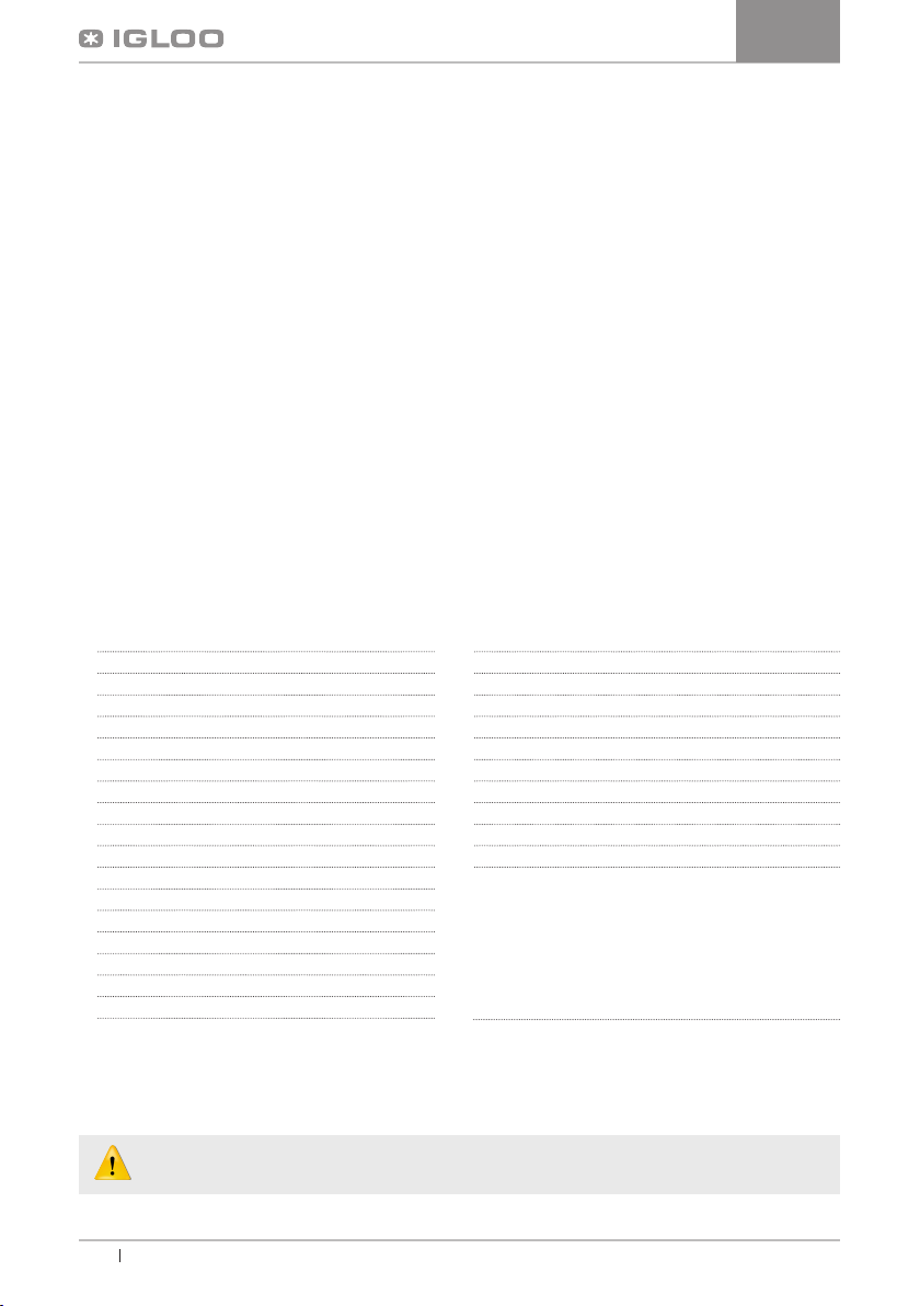
Fig.1 Layout of unit “Jamaica W OPEN” 2
Fig.2 Mounting the hook on the frame 3
Fig.3 Adjusting the height of hooks 4
Fig.4 Assembly/disassembly of glass elements 4
Fig.5 Control panel 4
Fig.6 Assembly/disassembly of suction 6
Fig.7 Cleaning the condenser 6
Fig.8 Replacing the uorescent lamp 7
Fig.9 Nameplate 8
Fig.10 “Igloo” thermostat panel 9
Fig.11 “Carel” thermostat panel 10
List of tables
Table 1 Technical data 2
This sign signies information of particular meaning for user security and for proper device
exploitation.
1
User manual Jamajka W OPEN www.igloo.pl
Page 2
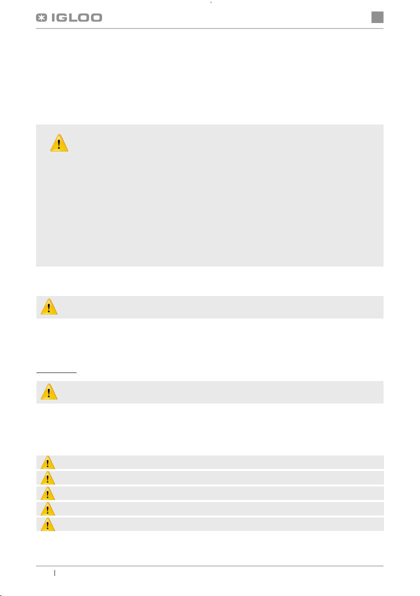
1 – Internal lighting
2 – Internal back (perforated – DO NOT BLOCK THE VENTS
to ensure chilled air circulation!)
3 – Shelf price strip
4 – Front glass grip
5 – Low front glass
6 – Airow channel
7 – Wooden housing
8 – Chiller unit
9 – Feet for leveling the unit
10 – Top shelf (roof) – wooden or stainless steel
11 – Rear of the unit (outer back)
12 – Display shelf (glass or stainless steel)
13 – Internal frame
14 – Internal countertop
15 – Control panel (thermostat, switches)
16 – Nameplate
17 – Windchest (After removing, access to the condenser ns is
available. DO NOT OBSTRUCT THE VENTS!!!
en
2.3. Technical data
Table 1 Technical data
Type of unit
1.3W Open* 230/50 4.7 144 16.2 10 - 190
1.3W Open-mod/A * 230/50 4.7 144 16.2 10 - 180
1.3W Open-mod/C * 230/50 - 144 - 10 700 170
0.9W Open * 230/50 3 72 10.1 10 - 140
0.9W Open-mod/A * 230/50 3 72 10.1 10 - 130
0.9W Open-mod/C * 230/50 - 72 - 10 700 120
0.6W Open* 230/50 2.2 60 7.7 10 - 90
0.6W Open-mod/A * 230/50 2.2 60 7.7 10 - 80
0.6W Open-mod/C * 230/50 - 60 - 10 700 70
Rated voltage
[V/Hz]
Rated current
[A]
Rated lighting
power [W]
Power
consumption
[kWh/24h]
Shelf load
[kg/m]
* Jamaica W Open” also has a wooden (RETRO/TREND) or stainless steel housing.
User manual Jamajka W OPENwww.igloo.pl
Cooling po-
wer demand
[W/mb]
Unit weight
[kg]
2
Page 3
en
3. PREPARING THE UNIT FOR OPERATION
3.1. Requirements for the installation site
• Check whether the cross-section of power cables is suitable for the current consumption of the installed equipment
• It is forbidden to connect the device via extension cables or distributors
• The unit must be connected to a separate, properly prepared electrical circuit with a socket with protective pin
(as per PBUE)
The unit may only be started after conrming the effectiveness of shock protection with the results of
measurements carried out in accordance with applicable regulations!
3.2. Connection and start-up
• Unpack the unit and remove the wooden pallet
• Place the unit on a level and sufciently solid surface, and then level it with the feet Fig.1/9 (p.3)
• Remove protective lm from the cabinet components
• First cleaning of the unit should be done after unpacking the unit and prior to start-up. The device should
be cleaned with water at a temperature not exceeding 40°C with added natural cleaning agents. Cleaning
and washing of the device must not be done using agents containing chlorine and different varieties
of sodium, as they damage the protective layer and the unit’s components! Any residual adhesive or
silicon on metal components may only be removed with petroleum ether (does not apply to plastics components!). Do not use other organic solvents.
Do not use water jets while washing the unit. The unit should be cleaned with a damp cloth.
• If the unit goes to the user partially disassembled for safety in transport, proceed as follows:
1. Install the hooks with the lamp in the frame
2. Fig.2/3 (p.5)
3. Place glass shelves on the frame and the internal countertop Fig.4/5,6 p.6) . Place glass components on silicon
parts (bumpons) Fig.4/8 (p.6).
Once the unit has been installed at its destination, leave it at rest for at least 2 hours before switching on
(for equipment with internal generator unit), so that the oil level settles to prevent problems with starting the
chiller!
WARNING: Protect the cooling circuit against damage!
• Place the plug of the connection cable directly into the socket (it is forbidden to connect the device via
extension cables or distributors!)
• Switch on the main switch Fig.5/1 (p.7), which will turn on the thermostat, and then the generator unit
• In the thermostat panel Fig.5/3(p.7) set temperature a (detailed operation at
p.14 or 15)
• Press the lighting switch Fig.5/2 (p.7)
1
2
3
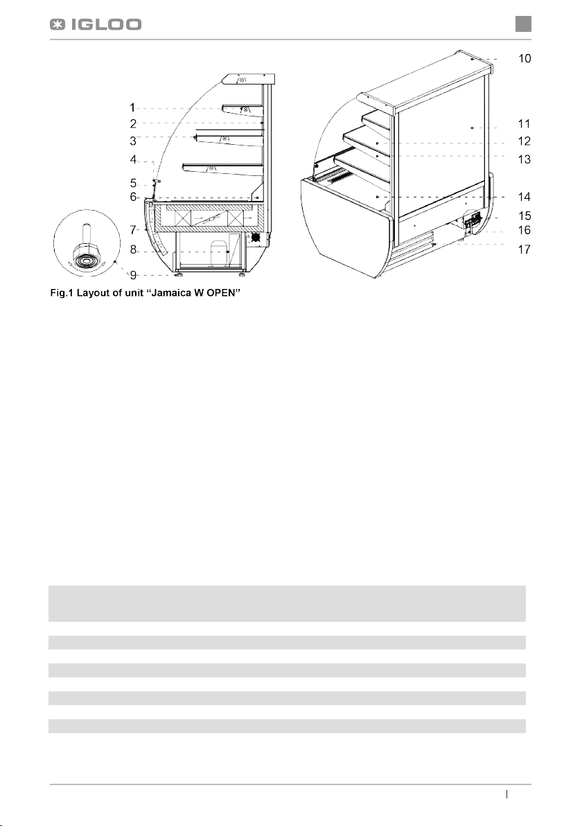
Fig.2 Mounting the hook on the frame
1 – Hook mounting holes
2 – Vertical pin of the internal frame
3– Hook (tted for three-step adjustment of the suspension angle)
3
User manual Jamajka W OPEN www.igloo.pl
Page 4
en
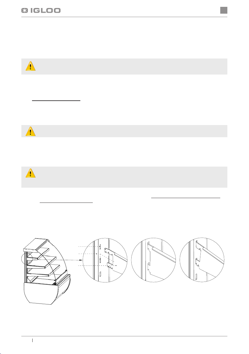
Fig.3 Adjusting the height of hooks
1 – Hook
2 – The conduit tube shielding the lamp cord
3 – PVC prole masking the frame’s vertical bar
To change the height of the hook, slightly tilt the PVC prole and drag
the conduit tube to the appropriate position. Then pull the hook from
the frame and place it in the appropriate position and angle.
1
2
3
4
1 2 3
5
6
1
1
2
2
3
4
260
440
530
525
Fig.4 Assembly/disassembly of glass elements
1 – Glass side
2 – Front glass grip
7
8
3 – Low front glass
4 – Top aluminum prole (tilting guide) of the glass
5 – Frame display shelf
6 – Countertop display shelf
7 – Bumpon – silicone element protecting glass components
from moving and providing better grip (Do not damage during
operation and maintenance!)
8 – Frame hook
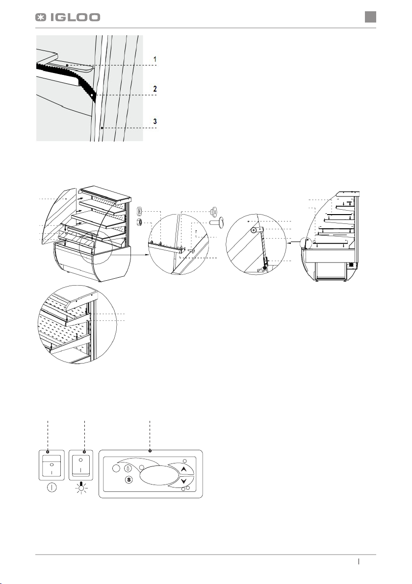
Fig.6 Control panel
1 – Main switch (turns on/off the aggregate of the
device)
2 – Lighting switch
3 – Thermostat (temperature regulator) panel (servi-
ce details – Chapter No. 7, p. 21 and 22)
User manual Jamajka W OPENwww.igloo.pl
4
Page 5
en
4. OPERATION
The cooling temperature and the work cycle of the unit may uctuate. They depend on a number of factors, e.g. the
amount and temperature of the products inside, and the ambient temperature.
Place the unit in a dry, well-ventilated place without direct sunlight, ensuring good air exchange (distance between
the wall and the device min. 10 cm), away from heat sources and devices forcing the airow (portable and ceiling
fans, blow heaters). The unit is functioning properly in an environment where the temperature is in the appropriate
climate class, as indicated on the nameplate. Operation of the device may deteriorate if the temperature was above
or below the indicated range for a long period.
4.1. Temperature control
NOTES AND TIPS
• Properly level the unit to prevent noisy operation and ensure proper (condensate) drainage during defrosting
• After transporting the unit, wait about 2 hours before restarting it
• When rst lling the cooling space, do so after it has cooled down to operating temperature.
This principle should also be observed after a long downtime
• Do not block any vents, as could hinder the circulation of cooled air. You should also provide proper
airow around the unit (in any case, do not cover the vents)t
• Ensure a uniform load on the shelves without exceeding their maximum load
• Keeping the condenser clean. Impurities may cause overheating of the compressor and ultimately lead
to failure, which is not covered by the warranty.
• Do not use electrical appliances inside the chamber for storing food products
For operation of thermostats (temperature controllers) “Igloo” and “Carel”, see section 7 (p.14 and 15).
The main task of the thermostat is to control the refrigerating unit, so as to reach the preset temperature within the unit and
keep it within certain ranges. All temperature control settings necessary for normal functioning of the unit are introduced
by the manufacturer. Before using the device, the user should check and set the desired temperature on the panel inside
the device.
Digital display – displays the current temperature inside the device
Any interference in the factory settings of the thermostat voids the warranty!
5. MAINTENANCE
5.1. Cleaning and maintenance
All maintenance services need to be performed after disconnecting the device from power supply!
Protect the electrical installation against damage or ooding
Do not use water jets while washing the unit. The unit should be cleaned with a damp cloth.
Do not use any sharp objects to remove lth!
Devices equipped with wheels cannot be used on uneven surfaces!
5
User manual Jamajka W OPEN www.igloo.pl
Page 6
en
1
2
Fig.6 Assembly/disassembly of suction
1 – Internal countertop
2 – Suction (DO NOT BLOCK the vents!!!)
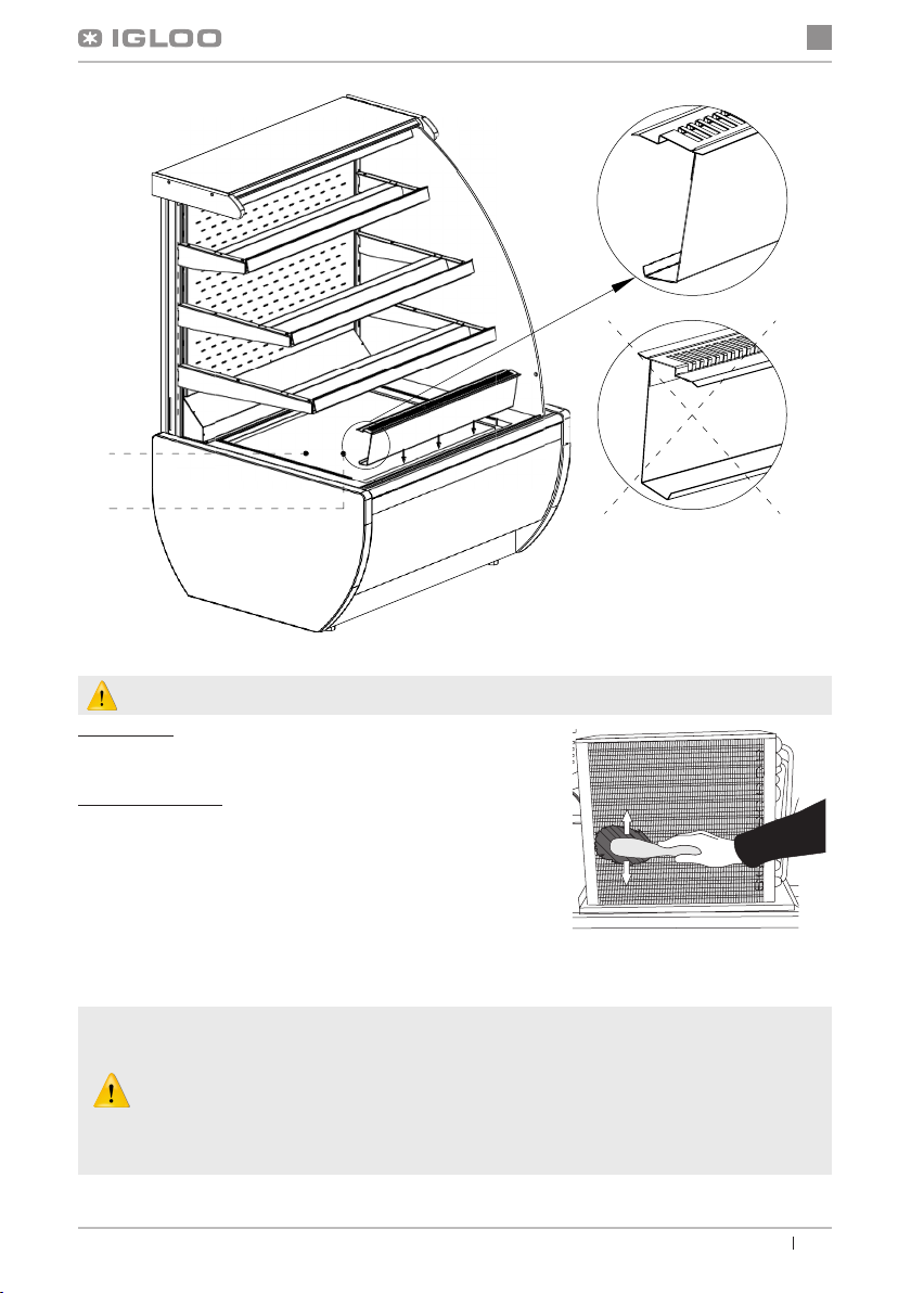
Do not use mechanical means in order to fasten the defrosting process!
Once a month it is recommended to stop the operation of the device
to clean the interior, provide natural defrosting of the evaporator and
to clean the condenser.
The unit’s evaporator should be kept clean. Impurities impede heat
transfer, resulting e.g. in increased electricity consumption and could
cause damage to the compressor unit.
To clean the condenser, unscrew the xing screws and remove the
windscreen. Clean the condenser ns with a soft brush. For strong
soiling (clogging the ns) of the condenser, it is advisable to use a
vacuum or compressed nitrogen to suck out/blow out the soil from
between the ns.
The manufacturer is not liable for damage to the condensing unit resulting from non-observance of
the condenser’s cleanliness!
Parts of the unit may corrode if used or maintained incorrectly. Follow the rules:
• Do not let surfaces of the unit to come into contact with agents containing chlorine and sodium
varieties that damage the protective layer and the unit’s components (including various grades
of stainless steel)
Fig.10 Condenser cleaning
User manual Jamajka W OPENwww.igloo.pl
6
Page 7
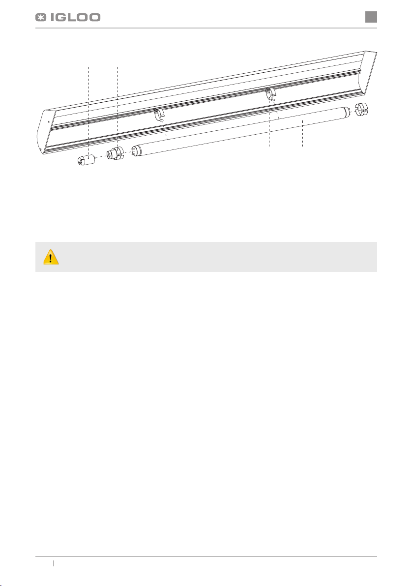
34
21
Fig.8 Replacing the uorescent lamp
1 – Lamp grip
2 – Lamp
3 – Light housing
4 – Fluorescent igniter
During maintenance work, be careful not to damage the nameplate Fig.9 (p.13), which contains
important information for maintenance workers and waste disposal companies.
6. SERVICE
6.1. Fault identication and repair
In case of any difculties during actuation of the device or during its exploitation, please return to these chapters in this
manual, which explain the performed operation. This aims to ensure that the device is properly operated. If you still
experience difculties, the following hints will help you solve the problem:
The device is not working... – Make sure that:
• The device is connected to the supply network
• Voltage and frequency in the network are compliant with those recommended by the producer, 230V/50Hz
• The main switch is turned on
• Thermostat is turned on (This concerns the Igloo thermostat – If only two spots are visible on the display – turn on
the thermostat)
The device is operating, but the lighting is off...– Make sure that:
• Lighting switch is turned on
• Fluorescent lamp or starting switch of the device is not burnt
The device does not reach the proper temperature, the lighting is on...– Make sure that:
• The main switch is on
• Temperature setting on the thermostat is properly set
• Thermostat works properly
• The condenser is clean, if necessary – clean the condenser
• Ambient temperature does not exceed 25ºC
• Enough time has passed for products to be cooled
• Ventilation holes of the device are not blocked
(This concerns the “IGLOO” thermostat) thermostat displays C0 or C1 or C2 instead of displaying temperature:
This situation shall occur, when one of temperature regulation sensors has been destroyed. The following
messages may be displayed in such case:
• C0 – temperature sensors inside the chamber are damaged – call authorized service
• C1 – failure of evaporator sensor - call authorized service
• C2 – failure of condenser alarm sensors (or failure of second evaporator sensor) – call authorized service
en
7
User manual Jamajka W OPEN www.igloo.pl
Page 8

(This concerns the “CAREL” thermostat) Thermostat displays E0 or E1 or L0 or HI or EE or Ed or DF instead
of temperature:
• E0 – failure of temperature sensor inside the chamber – call authorized service
• E1 – failure of evaporator sensor – call authorized service
• L0 – low temperature alarm (lower than temperature range set within the device – call authorized service
• HI – high temperature alarm – call authorized service
• EE – internal defect of the regulator – call authorized service
• Ed – max. defrosting time exceeded – call authorized service
• DF – defrosting in progress (this is not an alarm signal) – call authorized service
(This concerns the “IGLOO” thermostat) The device is working, sound signalling is activated...– Make sure that:
• The condenser is clean, if necessary – clean the condenser
• Condenser ventilator is working properly
• Ambient temperature does not exceed 25ºC
The device is working too loud...– Make sure that:
• The device is standing stably
• Furniture adjoining the device do not vibrate when the cooling aggregate compressor is working
Sounds made by equipment at work are normal. The equipment includes fans, motors and compressors, which turn on and off automatically. Every compressor produces a noise while at work. These
sounds are generated by the motor unit and by the refrigerant owing in the circuit. This phenomenon is a technical characteristic of refrigeration units and does not mean malfunction.
In the case of exceeding the ambient conditions as per third-class climate (relative humidity above 60%),
the phenomenon of water transfer from the system with automatic condensate evaporation (evaporator)
may be observed. This case does not mean malfunction and does not require a service call.
Deposition of condensation on the unit’s windows at high relative humidity above 60% is a natural phenomenon and does not require a service call!
en
6.2. Service
IGLOO service telephone number: +48 (14) 662 19 56 or +48 605 606 071 e-mail: serwis@igloo.pl
If after checking points described in chapter 6.1 “Fault identication and repair” the device still does not work properly,
please contact Technical Service of the Igloo company, stating the data from the data plate Fig.12 (p. 20):
• Serial number (NS)
• Production date
• Type (name of the device)
and
• Date when the device was purchased
• Description of the problem
• Your exact address and telephone number
(with the code number)
The above gure shows a demonstrative data plate and
the data stated on the plate are exemplary data, which
are not related with “Jamajka W OPEN” devices!
Fig.12 Data plate
User manual Jamajka W OPENwww.igloo.pl
8
Page 9

7. THERMOSTAT SERVICE
7.1. „IGLOO” thermostat
Fig.13 „Igloo” thermostat control panel
21 3 4 65
1 – Cooling on/off switch
2 – Manual defrosting switch
3 – Aggregate and defrosting operating control diode
4 – Temperature monitoring switch on defrosting sensor
5 – Temperature regulation switch (increase)
6 – Temperature regulation switch (decrease)
en
Verication of adjusted temperature (inside the device) – By pressing “▲” or “▼” switch once we can verify the adjusted
temperature. The adjusted temperature shall be shown on the display with a visible red blinking spot (diode). The preview
shall nish automatically after about 3 seconds.
Lowering (or increasing) the temperature – press “▼” (or “▲”) switch and the adjusted temperature shall be visible on
control panel. By pressing the “▼” switch we decrease the temperature to the desired value. The preview shall nish
automatically after about 3 seconds.
Manual defrosting – switch No. 2 enables to initiate the defrosting cycle at any moment when the device is working (re-
gardless of the automatic defrosting function); the switch shall not operate when the temperature is higher than the nal
defrosting temperature.
The user should switch on/ switch off the aggregate only by means of the main switch of the device, and
not by means of the direct switch on thermostat control panel. Switching on the main switch shall automatically initiate the thermostat!
* Read more on www.igloo.pl
9
User manual Jamajka W OPEN www.igloo.pl
Page 10

en
7.2. „CAREL” thermostat
Fig.14 „Carel” thermostat control panel
1
2
3
4
5
WHAT DO DIODES ON CONTROL PANEL SIGNIFY
Diode 1 is on - Compressor: the symbol is visible when the compressor is working. It is blinking when compressor
actuation is delayed by security procedure. It blinks in the following cycle: two blinks – pause, when the constant working
mode is activated.
Diode 2 is on - Ventilator: the symbol is visible when evaporator ventilators are turned on. It blinks when the actuation
of the ventilators is delayed by external disengagement or when another procedure is in progress.
Diode 3 is on - Defrosting: the symbol is visible when the defrosting function is activated. It blinks when the actuation
is delayed by external disengagement or when another procedure is in progress.
Diode 4 is on - Alarm: the symbol is visible when the alarm is activated.
5 – current temperature inside the device is displayed (decimal places displayed after the comma)
SETTING THE DESIRED TEMPERATURE
- press for 1 second
- increase or decrease the leading value by means of and , switches, until the desired value shall be obtained
- press
MANUAL INPUT OF THE DEFROSTING CYCLE
Defrosting shall be realised in an automatic mode. It is possible to force defrosting at any moment by pressing and holding
the
* Read more on www.alfaco.pl
once again in order to conrm the new value of the setting point;
switch for minimum 5 seconds. Diode No. 1 shall blink during manual defrosting.
leading value shall be displayed on the screen;
;
NOTE: IN CASE OF NOT OBSERVING THE PRINCIPLES ON CONNECTING AND USING THE DEVICE INCLUDED IN THIS MANUAL, THE PRODUCER SHALL RESERVE THE RIGHT TO RECEDE FROM OBLIGATIONS OF
THE GUARANTOR!!!
Information included in this document may be altered by “IGLOO” without noticing the user.
Copying the present manual without the consent of the producer is forbidden.
Images and drawings are of demonstrative character and may differ from the purchased device.
User manual Jamajka W OPENwww.igloo.pl
10
 Loading...