

Page 1
en
13
User manual INNOVAwww.igloo.pl
Contents List of Figures
1. UNLOADING 13
2. PROPERTIES OF THE DEVICE 13
2.1. Purpose 13
2.2. Description of the device 13
2.3. Technical data 15
3. PREPARING THE DEVICE FOR EXPLOITATION 16
3.1. Requirements concerning the place of installation 16
3.2. Connection and actuation 16
4. EXPLOITATION 16
4.1. Temperature regulation 17
4.2. Temperature regulation 17
5. MAINTENANCE 17
5.1. Cleaning and maintenance 17
6. SERVICE 19
6.1. Fault identication and repair 19
6.2. Service 20
7. THERMOSTAT SERVICE 20
7.1. „IGLOO” thermostat 20
7.2. „CAREL” thermostat 21
1. UNLOADING
The device should be transported in vertical position, and it should be properly secured and packed. The manufacturer
ships the device on a special wooden platform, secured with cardboard angle sections and foil.
2. PROPERTIES OF THE DEVICE
2.1. Purpose
The „INNOVA” display case is a universal cooling device for displaying and storage of short-term confectionery: tarts, cakes, biscuits, desserts, etc. at temperatures between +2°C / +15°C with ambient temperature +16°C / +25°C and relative
air humidity of up to 60%.
2.2. Description of the device
„INNOVA” is equipped in dynamic cooling, automatic condensation evaporation and defrosting. The display case is also
equipped with an electronic thermostat, which works optionally with the temperature registration module that enables
registration and signalling high and low temperatures in the unit. Display cases are adapted to connect in sequences and
can be powered by an internal unit within the temperature range of +2°C / +15°C. It is possible to control the humidity
of the display case ranging from 40 to 90%. The exhibition part of the display case are glass shelves placed on a rack.
The exposition shelves are able to change the position and angle of suspension. The glass elements are made of insulating glass lled with argon and black silk-screen printing. The „INNOVA” display cases use energy-saving LED back
lighting. „IGLOO” Units are made in accordance with modern technology and possess the certicates required by law.
This sign signies information of particular meaning for user security and for proper device
exploitation.
Instruction manual
INNOVA
en
Fig.1 Section of the device 14
Fig.2 Control panel 14
Fig.3 Construction of the unit 15
Fig.4 Humidistat 17
Fig.6 Cleaning the condenser 18
Fig.12 Data plate 19
Fig.13 „Igloo” thermostat control panel 20
Fig.14 „Carel” thermostat control panel 21
List of tables
Table 1 Technical data 2
Page 2
en
14
User manual INNOVA www.igloo.pl
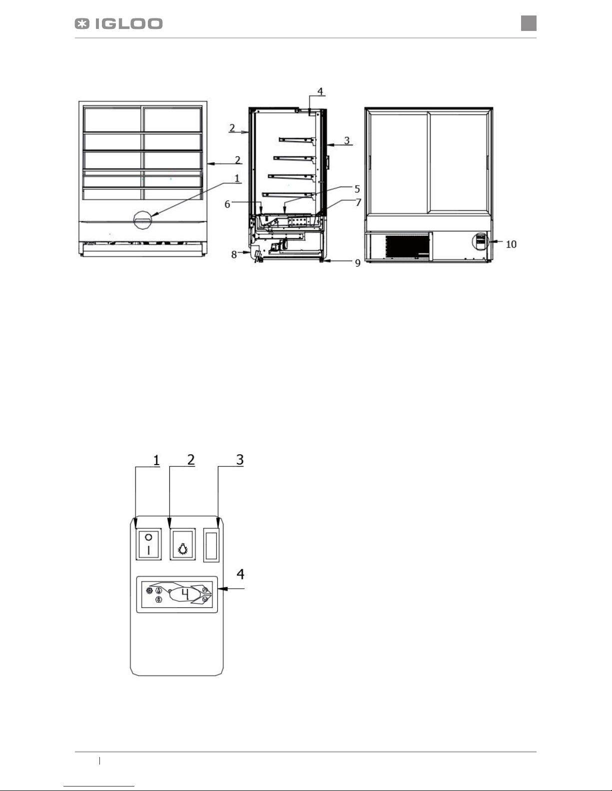
Rys.1 Section of the device
1 – The handle for opening the front glass
2 – Front glass
3 – Sliding or swing doors (model 70)
4 – Humidistat (humidity control system)
5 – Internal surfaces with glass shelf
6 – Suction (DO NOT BLOCK the vents!!!)
7 – Airow (DO NOT BLOCK the vents!!!)
8 – Plinth block
9 – Legs - used to level the unit
10 – Control panel (thermostat switches)
Rys.2 Control panel
1 – Main switch (switches on / off the unit)
2 – Light switch
3 – Electromagnetic lock the front glass extension
4 – Thermostat panel (temperature controller)
(the details of operating in Chapter 7
Page 3
en
15
User manual INNOVAwww.igloo.pl
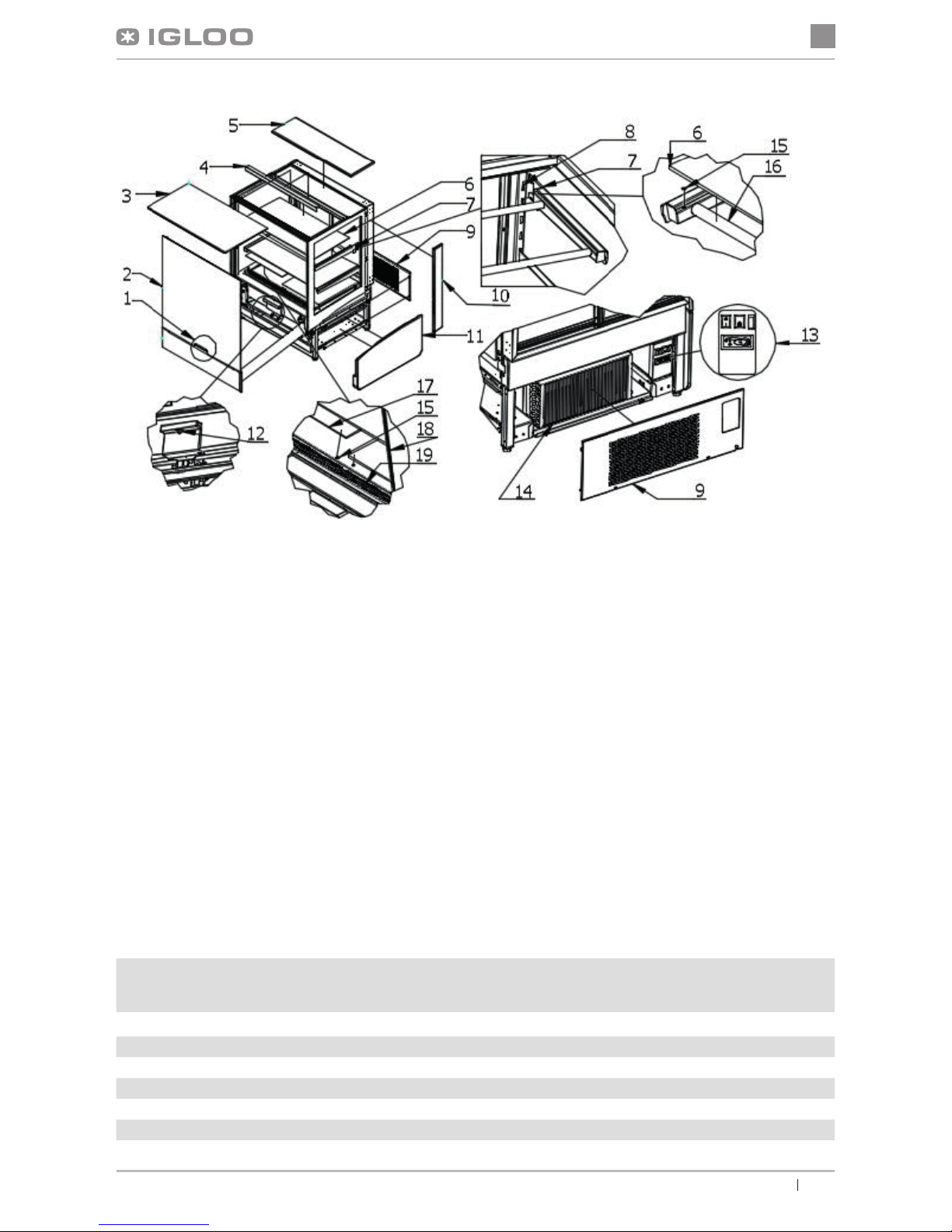
Fig.3 Construction of the unit
1 – The handle for opening the front glass
2 – Front glass
3 – Glass shelf (upper)
4 – Interior lighting (upper)
5 – Wooden top (of granite)
6 – Glass display shelves (on the rack and internal surfaces)
7 – Hook (adaptable to angle of suspension)
8 – Internal frame
9 – Fan (When removed access to the lamella condenser- DO NOT BLOCK the vents!!!)
10– Wooden side wing
11 – Wooden side
12 – Electromagnetic lock the front glass extension
13 – Control panel
14 – Lamella condenser (keep clean!)
15 – Bumbon – Silicone element protecting glass components from moving and allowing for better grip (Do not dama-
ge during operation and maintenance!!!)
16 – Aluminium prole - glass shelf support (with backlight)
17 – Internal surfaces with glass shelf
18 – Composite side glass with screen printing
19 – Airow (DO NOT BLOCK the vents!!!)
2.3. Technical data
Table 1 Technical data
Type of the device
„INNOVA”
Rated voltage
[V/Hz]
Rated lighting
power [W]
Electric energy
consumption
[kWh/24h]
Max shelf load
[kg/mb]
Usable surface
[m2]
INN70.110 230/50 26,4 8,0 33 175
INN100.110 230/50 34,2 9,6 33 220
INN140.110
230/50
42,9
10,833235
INN70.140
230/50338,333280
INN100.140
230/50
40,2
9,933340
INN140.140
230/50
49,5
11,133145
Page 4
en
16
User manual INNOVA www.igloo.pl
• Place the plug of the connecting cable directly in plug-in socket (it is forbidden to connect the device by
means of extension cords or dividers!)
• Turn on the main switch Fig.2/2 (p.14), which activates the thermostat, and then aggregate of the device
• Set the temperature on thermostat control panel Fig.2/1 (p.14) (thermostat service details on p.21 or 22)
• Turn on the lighting switch Fig.2/3 (p.14)
4. EXPLOITATION
Temperature of the cooled space and aggregate operating cycle may uctuate. They depend on numerous factors,
such as amount and temperature of products placed in the device and temperature of the surroundings.
The device should be placed in a dry and well-ventilated place, ensuring proper air exchange (distance between the
wall and the device – min. 10 cm), out of sunlight, kept far from heat sources and devices enforcing air ow (ceiling
and portable ventilators, blow-in heaters). The device functions properly in a room, where temperature falls within
appropriate climatic class stated on the data plate. The operation of the device may worsen when it shall operate in
temperature lower or higher than the stated temperature range.
Remarks and indications
• It is necessary to properly level the rack, which will prevent the device from noisy operation and will ensure
proper outow of the water (condensate) during defrosting.
• After transporting the device, wait about 2 hours before its actuation.
• In order to ensure proper conditions for the stored products, do not load the shelves completely. It is neces-
3. PREPARING THE DEVICE FOR EXPLOITATION
3.1. Requirements concerning the place of installation
• Verify whether the cross section of feeding conduits is proper for power consumption of the installed
device.
• It is forbidden to connect the device by extension rods or dividers.
• The device should be connected to the separate, properly made electric circuit with plug-in socket with
• protecting pin (according to PBUE /Regulations concerning Electric Equipment Construction/)
3.2. Connection and actuation
• Unpack the device and remove the wooden platform from the basis Fig.3 (p.15)
• The device should be placed on an even and on a sufciently hard base, and then level it with the help of
levelling feet.
• Remove the protection foil from the elements of the device (f. ex. from the inside of the device, display shelves, front fender beam)
• If the user shall obtain a device partially disassembled to secure it during transportation, perform the following
operations:
1. Fix hooks in frame rails Fig.3 (p.15)
2. Place shelves and/or baskets on hooks Fig.3 (p.15)
3. (Concerns the devices with internal aggregate) Place the condensate container on the basis of the aggregate,
under water outow hose (does not concern devices with automatic condensate evaporation) Fig.5 (p.18)
4. (Concerns the devices to be mounted on central aggregate) Defrosting water outow is located under the bottom of the body (about 10mm from the back of the rack, in the middle part of the body), which needs toallow
water outow to the sewage grit
• The rst cleaning of the device should be provide right after unpacking, and before turning it on. The unit
should be cleaned with water at a temperature not exceeding 40°C with a neutral detergent. For washing
and cleaning the equipment it is prohibited to use products containing chlorine and sodium varieties, which
destroy the protective layer and components of the device! Any residue of adhesives or silicone on metal
elements should be removed only with extraction naphtha (not applicable to items made of plastic !). Do
not use other organic solvents.
When cleaning the unit is prohibited to use water jet. The unit should be cleaned with a wet rag.
After installation of the device at the destination place it should be left to rest for at least 2 hours before
turning it on (for devices with built in compressor) to set the level of refrigerant in order to prevent problems
with starting up the aggregate.
WARNING: Keep out the cooling circuit from damage!
Page 5

en
17
User manual INNOVAwww.igloo.pl
sary to ensure even load of shelves and not to exceed the maximum load.
• The rst lling of cooling space should be performed after its previous cooling to working temperature. This
principle should also be observed after longer pause in exploitation.
• Do not block any ventilation holes, which would hamper circulation of the cooled air (Do not place the
products directly to the screen!). It is also necessary to ensure proper airow around the device (aggregate
ventilation holes cannot be covered).
• Keep the condenser clean. Impurities may lead to overheating of the compressor and as a consequence
may result in damage of the device, which is not covered by warranty.
• Do not use electric devices inside grocery product storing chamber.
• When the rack is used without the need to display goods (night work; closed post, shop) it is recommended to drop roller blinds in order to reduce consumption of electric energy
• Make sure whether the front panel is properly closed and whether it ts tight to the body of the device.
4.1. Temperature regulation
Service of “Igloo” and “Carel” thermostat (temperature regulators) is described in chapter 7
(p. 20 and 21)
The basic aim of a thermostat is to control the cooling aggregate to obtain the set temperature within the device
and maintain it within the determined temperature ranges. The producer enters all settings of temperature regulators required for normal functioning of the device. Before primary actuation the user should control and possibly
set the required temperature inside the device on the control panel.
Digital display – displays the current temperature inside the device.
It is forbidden to interfere with systemic parameters of the thermostat, as this can lead to serious
consequences, including the damage of the cooling device!
4.2. Humidity regulation
The humidistat controls the humidity, when the temperature in the unit is in the range from +10°C to +15°C. Using
the humidistat knob, set the desired humidity in the unit in the range from 40 to 90% by turning the knob and
setting it in place. Rotating the knob clockwise raises the humidity setting, and turning it in the opposite direction
reduces it.
5. MAINTENANCE
5.1. Cleaning and maintenance
All maintenance services need to be performed after disconnecting the device from power supply!
Protect electric installation against any damage or water spillage
Do not use water stream to clean the device, only a wet cloth
Do not use any sharp objects to remove lth!
Fig.4 Humidistat
Page 6
en
18
User manual INNOVA www.igloo.pl
Fig.5 Cleaning the condenser
Elements of device can corrode when improper used and maintenance. To avoid that please
follow the rules:
• Do not allow contact of the surface of the device with substances containing chlorine and / or baking
soda in different varieties, which destroy the protective layer and components of the device (also
includes various stainless steel)
During maintenance services it is necessary to pay attention not to damage the data place of the
device Fig.13 (p.10), which contains signicant information for servicing organs and waste removal
companies.
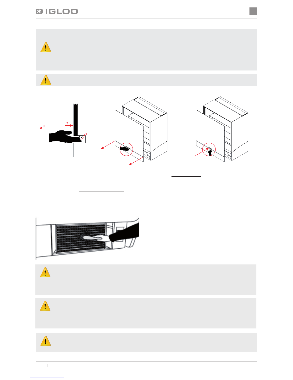
The device uses a retractable front panel system with an electromagnetic lock blocking the slide.
To slide the glass out, switch on the open/close lock button on the control panel at the back of
the unit, and then press the release lock, while slightly pressing against the wooden casing for
the lock to let go. To draw the front glass back in, lightly press near the lock for the lock button to
switch on. To completely prevent from opening the front glass by unauthorized persons, turn off
the power of the electromagnet on the operating panel.
While drawing the glass front back in, press against it slightly where the lock is, and not in the upper part!
It is recommended to make a break in the exploitation of the device once a month in order to clean its interior,
naturally defrost the evaporator and clean the condenser.
It is essential to keep the condenser of the device clean. Dirt may hinder the heat exchange, causing mainly increase in electric
energy consumption and may cause damage of aggregate compressor.
In order to clean the condenser it is necessary to unscrew the sheet metal screws and pull the wind brace out of catch by lifting it
up. Clean condenser lamellas with help of soft brush or paint brush. If the condenser is extremely dirty (blocking of lamellas) it is
indicated to use vacuum cleaner or compressed nitrogen to suck / blow the dirt from between lamellas.
Page 7

en
19
User manual INNOVAwww.igloo.pl
The producer shall not be held responsible for damages of the condenser aggregate resulting
from non-observance of condenser cleanliness !
6. SERVICE
6.1. Fault identication and repair
In case of any difculties during actuation of the device or during its exploitation, please return to these chapters in this
manual, which explain the performed operation. This aims to ensure that the device is properly operated. If you still
experience difculties, the following hints will help you solve the problem.
The device is not working... – Make sure that:
• The device is connected to the supply network
• Voltage and frequency in the network are compliant with those recommended by the producer, 230V/50Hz
• The main switch is turned on
• Thermostat is turned on (This concerns the Igloo thermostat – If only two spots are visible on the display – turn on
the thermostat)
The device is operating, but the lighting is off...– Make sure that:
• Lighting switch is turned on
• Fluorescent lamp or starting switch of the device are not burnt
Water leakage from under the device
• Check whether the device is properly levelled
• Empty the condensate container
The device does not reach the proper temperature, the lighting is on...– Make sure that:
• The main switch is on
• Temperature setting on the thermostat is properly set
• Thermostat works properly
• The condenser is clean, if necessary – clean the condenser
• Ambient temperature does not exceed 25ºC
• Enough time has passed for products to be cooled
• Ventilation holes of the device are not blocked
(This concerns the “IGLOO” thermostat) thermostat displays C0 or C1 or C2 instead of displaying temperature:
This situation shall occur, when one of temperature regulation sensors has been destroyed. The following
messages may be displayed in such case:
• C0 – temperature sensors inside the chamber are damaged – call authorized service
• C1 – failure of evaporator sensor - call authorized service
• C2 – failure of condenser alarm sensors (or failure of second evaporator sensor) – call authorized service
(This concerns the “CAREL” thermostat) Thermostat displays E0 or E1 or L0 or HI or EE or Ed or DF instead
of temperature:
• E0 – failure of temperature sensor inside the chamber – call authorized service
• E1 – failure of evaporator sensor – call authorized service
• L0 – low temperature alarm (lower than temperature range set within the device – call authorized service
• HI – high temperature alarm – call authorized service
• EE – internal defect of the regulator – call authorized service
• Ed – max. defrosting time exceeded
• DF – defrosting in progress (this is not an alarm signal)
(This concerns the “IGLOO” thermostat) The device is working, sound signalling is activated...– Make sure that:
• The condenser is clean, if necessary – clean the condenser
• Condenser ventilator is working properly
• Ambient temperature does not exceed 25ºC
The device is working too loud...– Make sure that:
• The device is standing stably and is properly levelled
• Furniture adjoining the device do not vibrate when the cooling aggregate compressor is working
Page 8
en
20
User manual INNOVA www.igloo.pl
• Enough time has passed for products to be cooled
• Ventilation holes of the device are not blocked
(This concerns the “IGLOO” thermostat) thermostat displays C0 or C1 or C2 instead of displaying temperature:
This situation shall occur, when one of temperature regulation sensors has been destroyed. The following
messages may be displayed in such case:
• C0 – temperature sensors inside the chamber are damaged – call authorized service
• C1 – failure of evaporator sensor - call authorized service
• C2 – failure of condenser alarm sensors (or failure of second evaporator sensor) – call authorized service
(This concerns the “CAREL” thermostat) Thermostat displays E0 or E1 or L0 or HI or EE or Ed or DF instead
of temperature:
• E0 – failure of temperature sensor inside the chamber – call authorized service
• E1 – failure of evaporator sensor – call authorized service
• L0 – low temperature alarm (lower than temperature range set within the device – call authorized service
• HI – high temperature alarm – call authorized service
• EE – internal defect of the regulator – call authorized service
• Ed – max. defrosting time exceeded
• DF – defrosting in progress (this is not an alarm signal)
(This concerns the “IGLOO” thermostat) The device is working, sound signalling is activated...– Make sure that:
• The condenser is clean, if necessary – clean the condenser
• Condenser ventilator is working properly
• Ambient temperature does not exceed 25ºC
The device is working too loud...– Make sure that:
• The device is standing stably and is properly levelled
• Furniture adjoining the device do not vibrate when the cooling aggregate compressor is working
6.2. Service
IGLOO service telephone number: +48 (14) 662 19 56 or +48 605 606 071 e-mail: serwis@igloo.pl
If after checking points described in chapter 6.1 “Fault identication and repair” the device still does not work
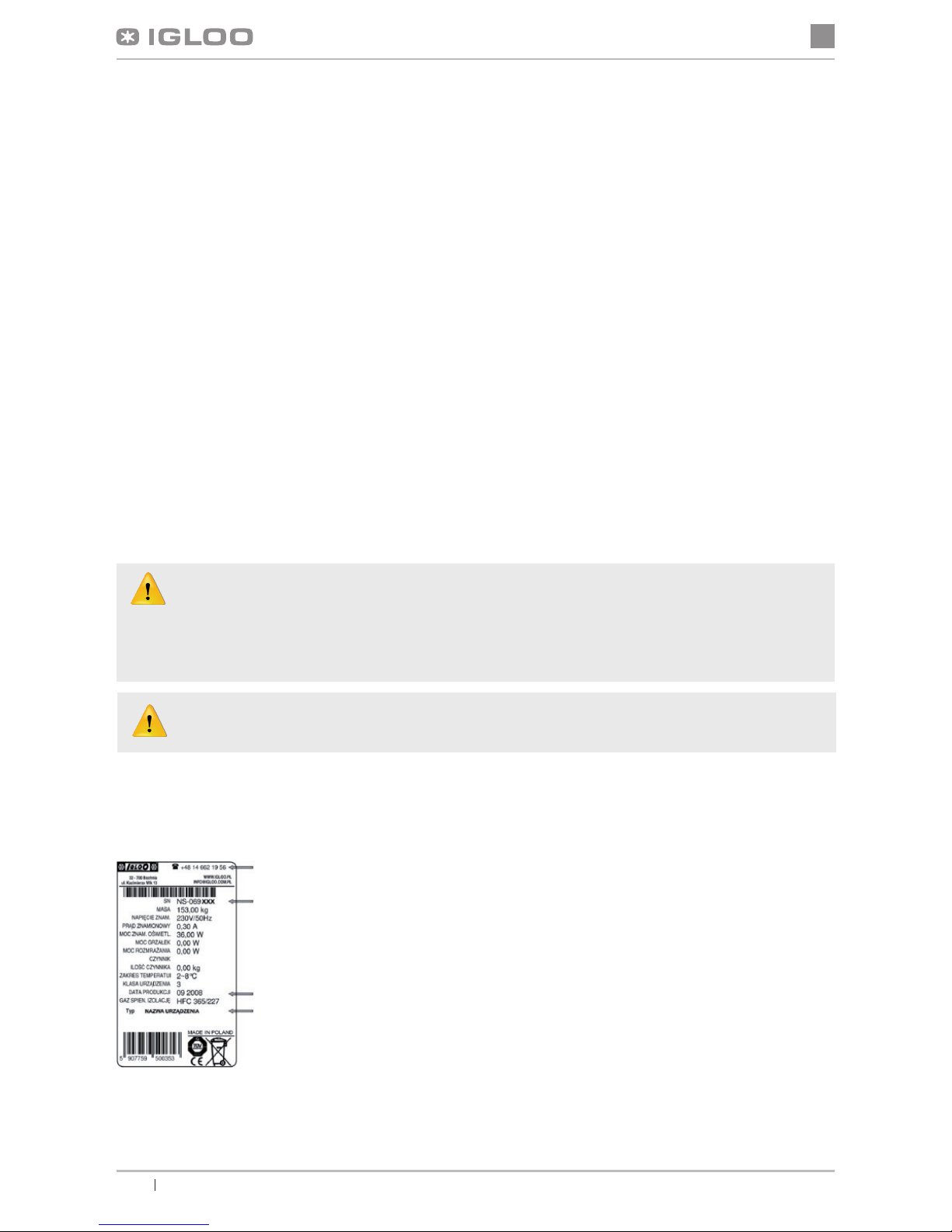
properly, please contact Technical Service of the Igloo company, stating the data from the data plate Fig.13 (p.10)
• Serial number (NS)
• Production date
• Type (name of the device)
and
• Date when the device was purchased
• Description of the problem
• Your exact address and telephone number
(with the code number)
• The data plate is located inside the device, on the screen, in its right upper corner
Noises made by the operating device are a normal phenomenon. The devices are equipped with ventilators,
engines and compressors, which turn on and off automatically. Each compressor makes certain noises
when operating. These sounds are made by the aggregate engine and by cooling agent owing through the circuit. This phenomenon constitutes a technical feature of cooling devices and it does not
signify their faulty work.
Steam precipitation on glasses of the device is a normal phenomenon in case of high relative air humidity
exceeding 60% and does not require calling the service
Fig. 12 Data plate
Page 9
en
21
User manual INNOVAwww.igloo.pl
The above gure shows a demonstrative data plate and the data stated on the plate are exemplary
data, which are not related with INNOVA device!
7. THERMOSTAT SERVICE
7.1. „IGLOO” thermostat
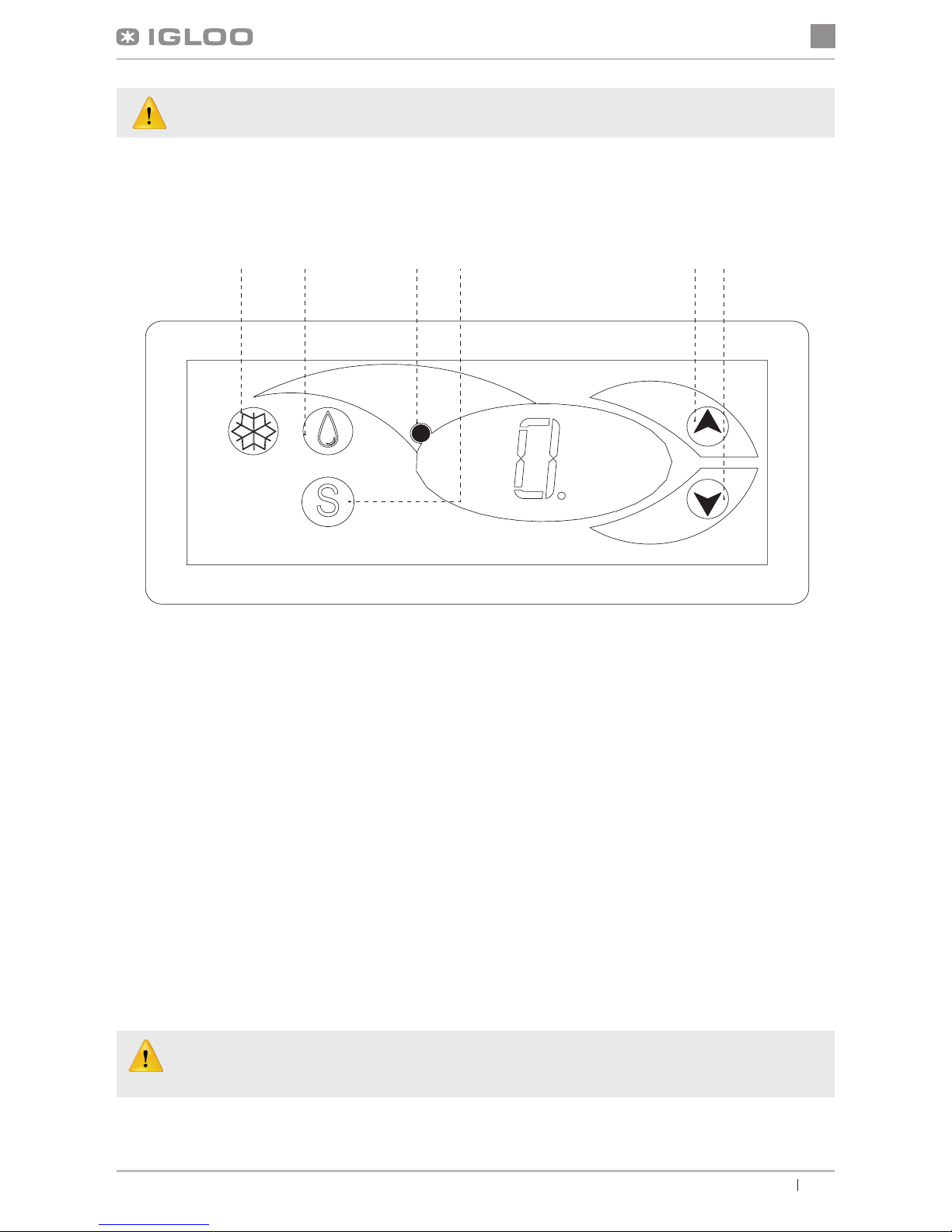
Fig.13 „Igloo” thermostat control panel
Verication of adjusted temperature (inside the device) – By pressing “▲” or “▼” switch once we can verify the adjusted
temperature. The adjusted temperature shall be shown on the display with a visible red blinking spot (diode). The preview
shall nish automatically after about 3 seconds.
Lowering (or increasing) the temperature – press “▼” (or “▲”) switch and the adjusted temperature shall be visible on
control panel. By pressing the “▼” switch we decrease the temperature to the desired value. The preview shall nish
automatically after about 3 seconds.
Manual defrosting – switch No. 2 enables to initiate the defrosting cycle at any moment when the device is working (regardless of the automatic defrosting function); the switch shall not operate when the temperature is higher than the nal
defrosting temperature.
The user should switch on/ switch off the aggregate only by means of the main switch of the device, and
not by means of the direct switch on thermostat control panel. Switching on the main switch shall automatically initiate the thermostat!
* Read more on www.igloo.pl
1 – Cooling on/off switch
2 – Manual defrosting switch
3 – Aggregate and defrosting operating control diode
4 – Temperature monitoring switch on defrosting sensor
5 – Temperature regulation switch (increase)
6 – Temperature regulation switch (decrease)
21 3 4 65
Page 10
en
22
User manual INNOVA www.igloo.pl
7.2. „CAREL” thermostat
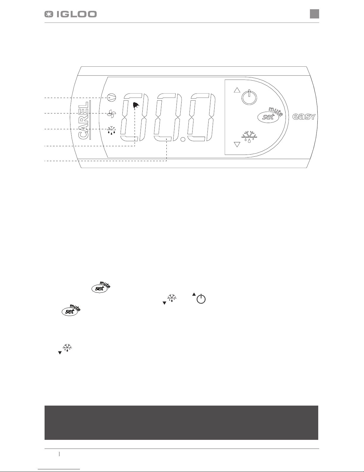
Fig.14 „Carel” thermostat control panel
WHAT DO DIODES ON CONTROL PANEL SIGNIFY
Diode 1 is on - Compressor: the symbol is visible when the compressor is working. It is blinking when compressor
actuation is delayed by security procedure. It blinks in the following cycle: two blinks – pause, when the constant working
mode is activated.
Diode 2 is on - Ventilator: the symbol is visible when evaporator ventilators are turned on. It blinks when the actuation
of the ventilators is delayed by external disengagement or when another procedure is in progress.
Diode 3 is on - Defrosting: the symbol is visible when the defrosting function is activated. It blinks when the actuation
is delayed by external disengagement or when another procedure is in progress.
Diode 4 is on - Alarm: the symbol is visible when the alarm is activated.
5 – current temperature inside the device is displayed (decimal places displayed after the comma)
SETTING THE DESIRED TEMPERATURE
- press for 1 second leading value shall be displayed on the screen;
- increase or decrease the leading value by means of and , switches, until the desired value shall be obtained
;
- press once again in order to conrm the new value of the setting point;
MANUAL INPUT OF THE DEFROSTING CYCLE
Defrosting shall be realised in an automatic mode. It is possible to force defrosting at any moment by pressing and holding
the
switch for minimum 5 seconds. Diode No. 1 shall blink during manual defrosting.
* Read more on www.alfaco.pl
NOTE: IN CASE OF NOT OBSERVING THE PRINCIPLES ON CONNECTING AND USING THE DEVICE INCLUDED IN THIS MANUAL, THE PRODUCER SHALL RESERVE THE RIGHT TO RECEDE FROM OBLIGATIONS OF
THE GUARANTOR!!!
Information included in this document may be altered by “IGLOO” without noticing the user.
Copying the present manual without the consent of the producer is forbidden.
Images and drawings are of demonstrative character and may differ from the purchased device.
1
2
3
4
5
Page 11

en
23
User manual INNOVAwww.igloo.pl
Correspondence:
Stary Wiśnicz 289, 32-720 Nowy Wiśnicz
Poland
NIP: 868-000-50-40
Tel.: +48 14/662 19 10, fax: +48 14/662 19 12, e-mail: info@igloo.pl
www.igloo.pl
 Loading...