

Iget HGDVK-84408, HGDVK-44404, HGDVK-84402, HGDVK-84404, HGDVK-164408 Quick Start Manual
...
Helpdesk / Technical Support
www.iget.eu/cs/helpdesk-centrum-cs
https://helpdesk.intelek.cz/

SMART
DETECTION
MOTION & HEAT TRIGGER ACCURATE ALERTS
H
eat-sensing HD CCTV Kit
Quick Start Guide - EN
For the latest, up-to-date manual, please visit
www.iget.eu
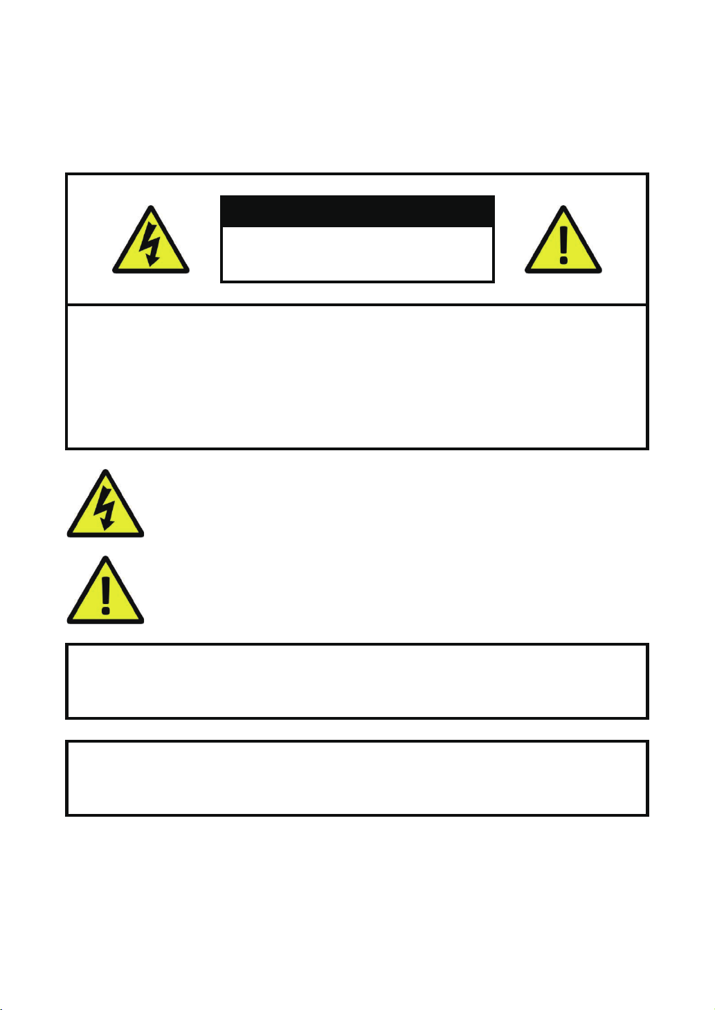
CAUTION
RISK OF ELECTRIC SHOCK
DO NOT OPEN
TO REDUCE THE RISK OF ELECTRIC SHOCK,
DO NOT REMOVE THE COVER.
NO USER SERVICABLE PARTS INSIDE.
REFER SERVICING TO QUALIFIED PERSONNEL.
The lightning flash with arrowhead symbol, within an equilateral triangle, is intended to alert
the user to the presence of non-insulated “dangerous voltage” within the product’s enclosure
that may be of sufficient magnitude to constitute a risk of electric shock.
The exclamation point within an equilateral triangle is intended to alert the user to the
presence of important operating and maintenance (servicing) instructions in the literature
accompanying the appliance.
1
WARNING:
CAUTION:
TO PREVENT FIRE OR SHOCK HAZARD, DO NOT
EXPOSE THIS UNIT TO RAIN OR MOISTURE
TO PREVENT ELECTRIC SHOCK, ENSURE THE PLUG
IS FULLY INSERTED INTO A MAINS SOCKET

IMPORTANT SAFEGUARD
All lead-free products offered by the company comply with the requirements of the
RoHS
conform
European law of the Restriction of Hazardous Substances (RoHS) directive, which means
our manufacturing processes and products are strictly “lead-free” and without the
hazardous substances cited in the directive.
The crossed-out wheeled bin mark symbolizes that within the European Union the
product must be collected separately at the product’s end-of-life. This applies to your
product and any peripherals marked with this symbol. Do not dispose of these products
as unsorted municipal waste. Contact your local dealer for procedures for recycling this
equipment.
DISCLAIMER
We reserve the right to revise or remove any content in this manual at any time. We do not warrant or assume any
legal liability or responsibility for the accuracy, completeness, or usefulness of this manual. The content of this
manual is subject to change without notice.
RECOMMENDATIONS
• AVOID DUSTY LOCATIONS:
• INSTALL IN VENTILATED SPACE:
• DO NOT EXPOSE TO MOISTURE:
• DO NOT DROP:
• DO NOT OPEN CHASSIS:
Excessive build-up of dust may cause the unit to fail.
Ensur
e adequate airflow around the DVR to prevent overheating.
Exposing the unit to water poses high risk of electric shock.
Doing so could damage internal components.
No user-serviceable parts inside.
TRADEMARKACKNOWLEDGEMENTS
• Internet Explorer™, Microsoft™&Windows™ are registered trademarks of Microsoft Corporation.
• Apple™, iPhone™, iPad™ and iTunes™ are registered trademarks of Apple Computer, Inc.
• AndroidTM and Google Play™ are registered trademarks of Google Inc
WARRANTY AND TECHNICAL SUPPORT
To help you make the most of this product you’ll find a host of information including full product manuals, FAQ,
troubleshooting guides and a support service if you have specific questions, available at our support website :
homeguardworld.com/support.
2

CONTENTS
CONNECTING YOUR SYSTEM
4
BASIC OPERATION
13
5
Introduction
6
Package Contents
7
DVR Layout
9
Connecting the DVR
10
Mounting the Cameras
11
Using Remote Control
12
Using the Mouse
14
Start-up Wizard
17
Main Interface
19
PIR Setup
20
Record
21
Playback
CONNECTING SMART DEVICE
22
CONNECTING TO PC&MAC
28
TECHNICAL SUPPORT
36
23
Before Start
23
Get the App
24
User Interface
25
For iPhone
26
For iPad
27
For Android Phone
29
Homeguardsafe Software for PC & Mac
32
Remote Access via Web Client
35
Cloud Access
37
Technical Specifications
38
Technical Q&A
39
Warranty & Support
40
Camera Installation Template
3

CONNECTING
YOUR SYSTEM
1
4

1.1 Introduction
Congratulations on your purchase of this Homeguard Hybrid DVR. Homeguard offers a complete CCTV solution for
home or office security, featuring high quality cameras, easy setup and configuration, motion detection and network
connectivity.
This system features:
• H.264 Video compression and G.711 audio compression
• Support CVBS, AHD, TVI, CVI and IPC
• Provides a convenient User Interface
• 4/8 CH Composite Input Connectors
• Supports 1080p/720p/960H/D1/CIF recording formats
• With the network specific codec, network transfer enabled regardless of the recording conditions
• Hard Disk overwrite function
• Mass storage hard disk backup through high-speed USB 2.0
• Simultaneous Record and Playback of 4/8/16-channel video data
• Various Search Modes (Search by Time, Event, Backup and Motion Detection)
• Various Recording Modes (Manual, Scheduled Recording)
• Remote Monitoring function by Network Viewer and Mobile Viewer
5
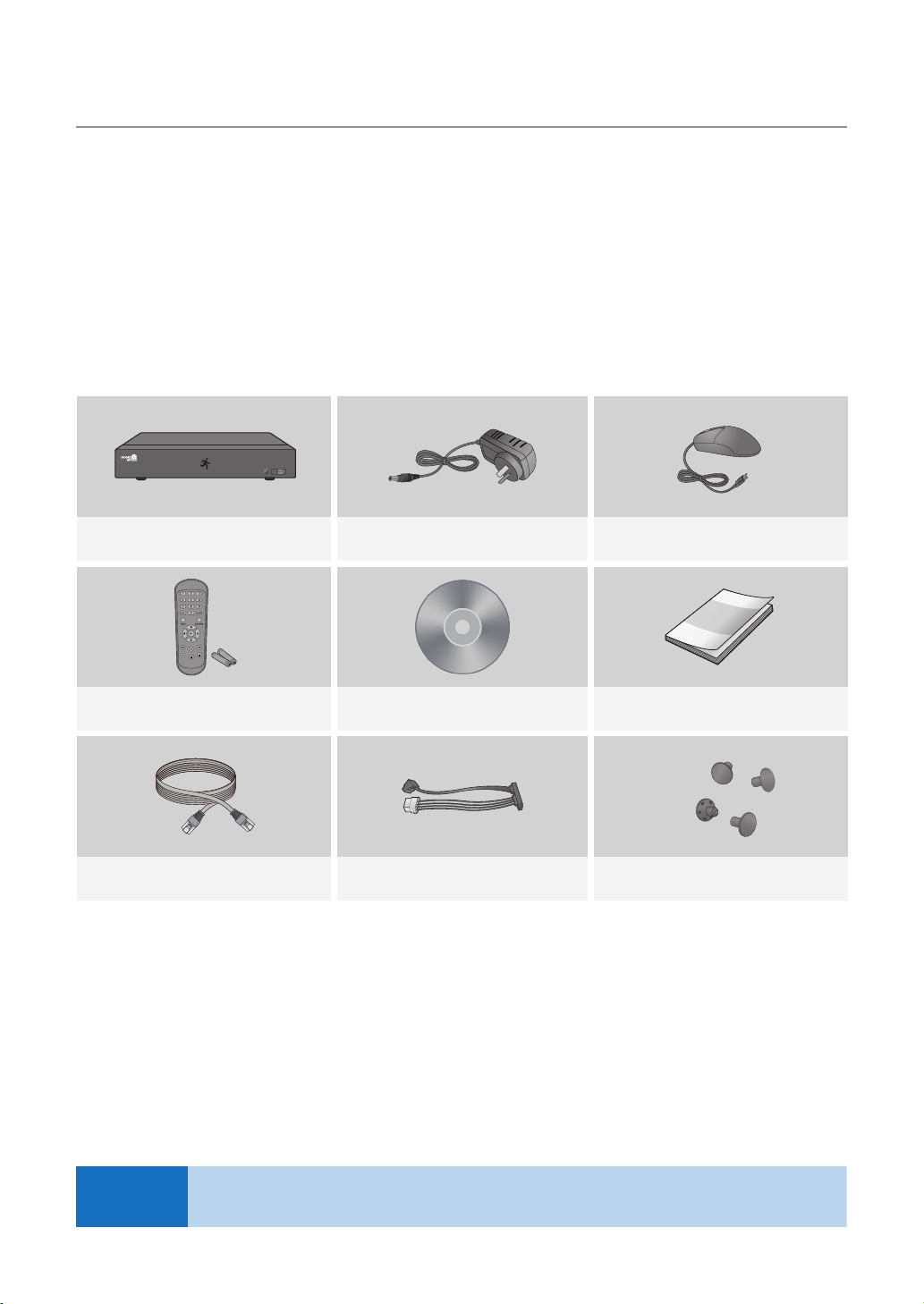
1.2 Package Contents
Please unwrap the product, and place the product on a flat place or in the place to be installed.
Please check the following contents are included in addition to the main unit.
• The appearance of the components may differ from the image shown.
• Accessory category and quantity may differ depending on sales region.
Check the contents of your DVR package against this checklist. If anything is missing or damaged, please do not use
the system, and inform your supplier as soon as possible.
HDD NET PWR
1080P HD DIGITAL VIDEO RECORDER
Hybrid DVR Power Adapter Mouse
USB
NOTE
User Manual / SoftwareRemote Control / Battery (AAA x 2) Quick Start Guide
Ethernet Cable
SATA Cable
(for models having no installed HDD)
This manual covers both 4 channel and 8 channel versions of the Homeguard DVR kits model:
HGDVK-44402 / 44404 / 84402 / 84404 / 84408 / 164408 / 164416.
HDD Fixing Screw
6
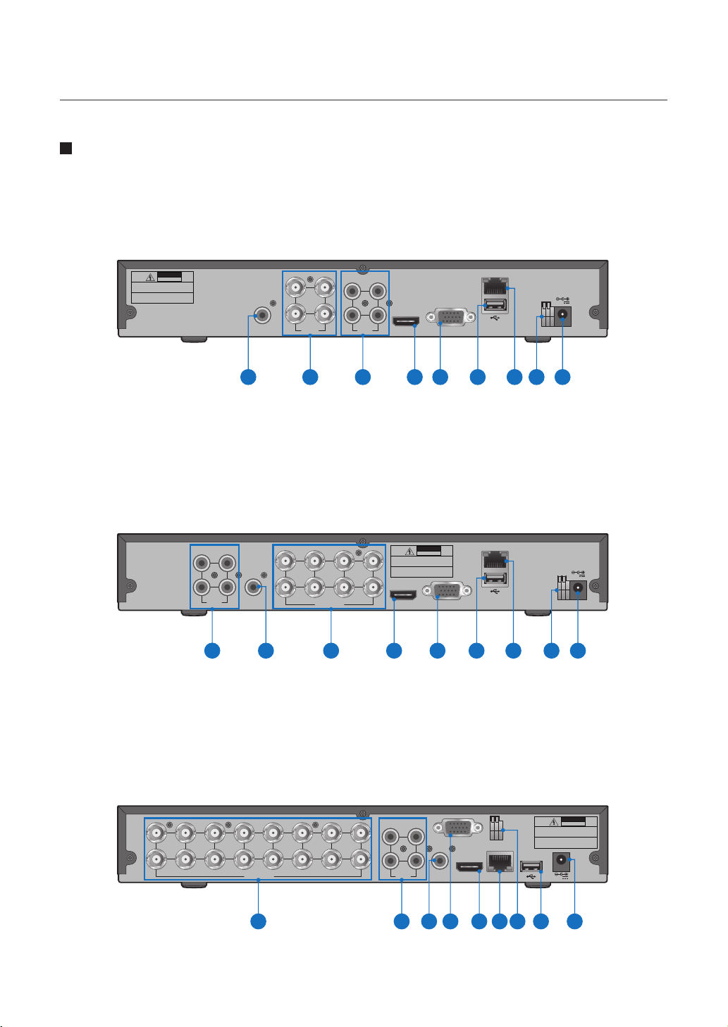
1.3 DVR Layout
Rear Panel
4CH DVR
DVR Kits Model: HGDVK-44402 / 44404
CAUTION
RISK OF ELECTRIC SHOCK
DO NOT OPEN
CAUTION : TO REDUCE THE RISK OF ELECTRICAL SHOCK
DO NOT OPEN COVERS. NO USER SERVICEABLE
PARTS INSIDE. REFER SERVICING TO QUALIFIED
SERVICE PERSONNEL.
WARNING : TO PREVENT FIRE OR SHOCK HAZARD. DO NOT
EXPOSE UNITS NOT SPECIFICALLY DESIGNED
FOR OUTDOOR USE TO RAIN OR MOISTURE.
AUDIO
OUTPUT
1 2 3 4 5 6 7 8 9
8CH DVR
DVR Kits Model: HGDVK-84402 / 84404 / 84408
31
2 4
AUDIO
INPUT
2 8
AUDIO
OUTPUT
1 23 4 5 6 7 8 9
3 1
4 42 2
VIDEO
INPUT
3
1
4
VIDEO INPUT
AUDIO
INPUT
5 7
6
13
HDMI VGA
CAUTION : TO REDUCE THE RISK OF ELECTRICAL SHOCK
DO NOT OPEN COVERS. NO USER SERVICEABLE
PARTS INSIDE. REFER SERVICING TO QUALIFIED
SERVICE PERSONNEL.
WARNING : TO PREVENT FIRE OR SHOCK HAZARD. DO NOT
EXPOSE UNITS NOT SPECIFICALLY DESIGNED
FOR OUTDOOR USE TO RAIN OR MOISTURE.
HDMI VGA
CAUTION
RISK OF ELECTRIC SHOCK
DO NOT OPEN
LAN
+ -
12V
RS485
LAN
+ -
12V
RS485
16CH DVR
DVR Kits Model: HGDVK-164408 / 164416
11
13
15
14
16
7
VIDEO INPUT
CAUTION
RISK OF ELECTRIC SHOCK
13
AUDIO
OUTPUT
VGA
+ -
RS485
HDMI
LAN
1
3
5
7
9
2
4
6
8
1012
4 2
AUDIO
INPUT
DO NOT OPEN
CAUTION : TO REDUCE THE RISK OF ELECTRICAL SHOCK
DO NOT OPEN COVERS. NO USER SERVICEABLE
PARTS INSIDE. REFER SERVICING TO QUALIFIED
SERVICE PERSONNEL.
WARNING : TO PREVENT FIRE OR SHOCK HAZARD. DO NOT
EXPOSE UNITS NOT SPECIFICALLY DESIGNED
FOR OUTDOOR USE TO RAIN OR MOISTURE.
12V
132 5 4 7 68 9
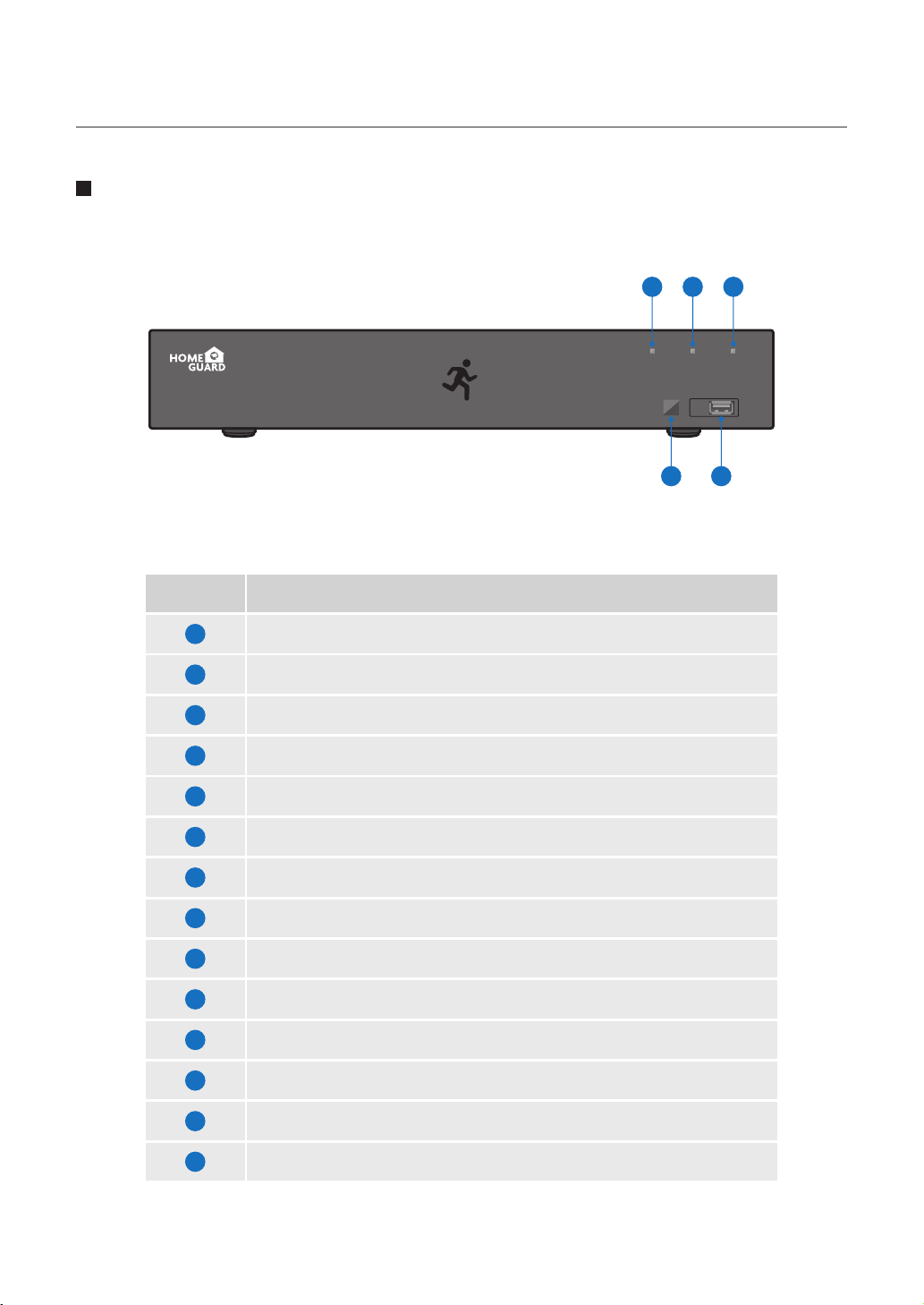
Front Panel
10 11 12
HDD NET PWR
1080P HD DIGITAL VIDEO RECORDER
Part Names Functions
1
2
3
4
5
6
7
8
RCA Audio Output: For speakers
4x / 8x / 16x BNC Video Connectors: For each camera input
4x RCA Audio Connectors: For each audio input*
HDMI Output: For most modern TVs
VGA Output: For most monitors
USB Ports: For USB mouse and external storage
LAN Port: To connect your DVR to the network
RS485: Connect to PTZ devices
USB
13 14
9
10
11
12
13
14
Power Connector: To power the DVR
HDD LED: Flashes when the HDD is in use
Network LED: Flashes when the internet is connected
Power LED: Indicates the DVR is turned ON when lit
IR Receiver: Receives the signal from the remote control
USB Ports: For USB mouse and external storage
8
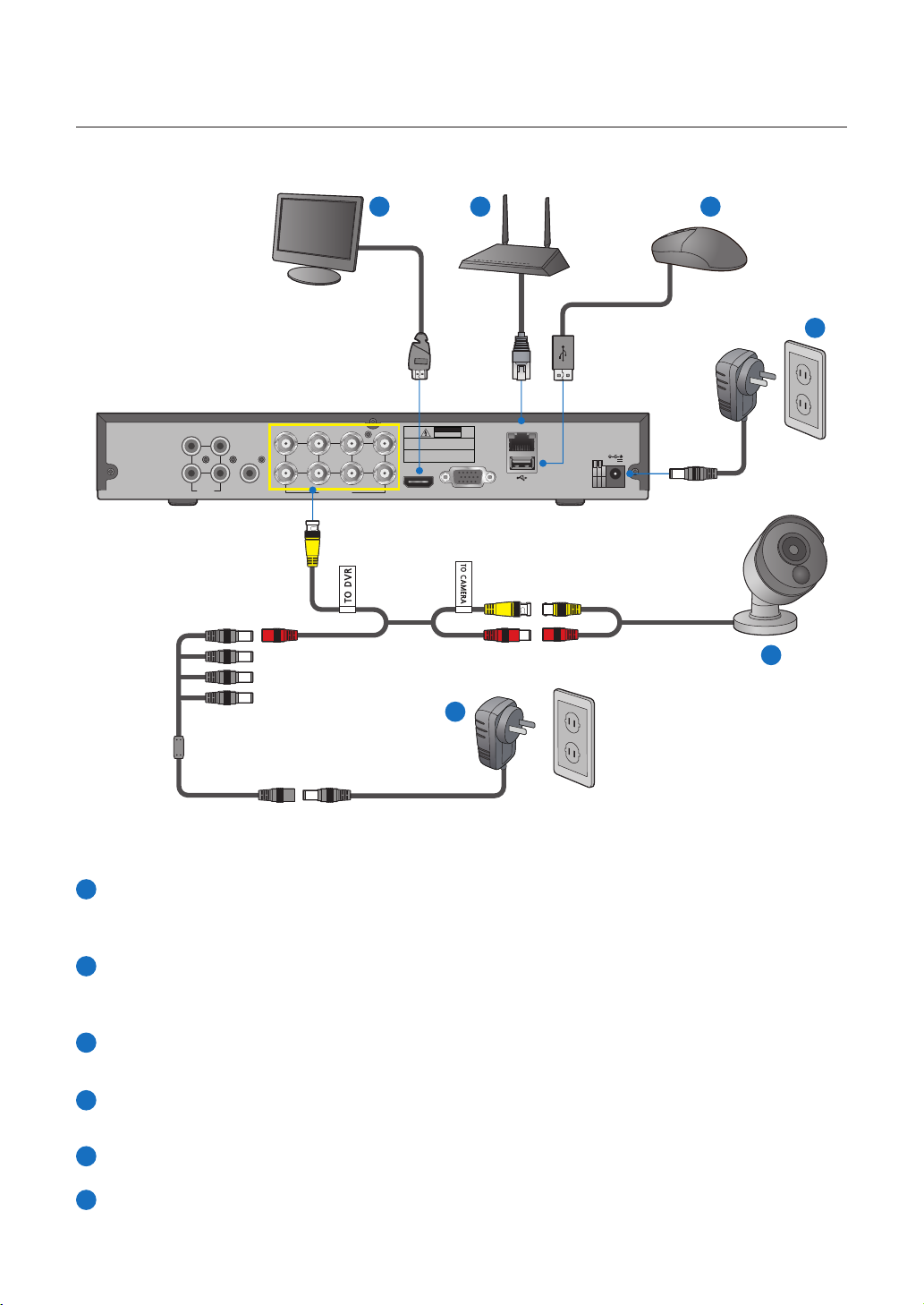
1.4 Connecting the DVR
53 4
6
LAN
+ -
12V
RS485
2 4
AUDIO
INPUT
5 7
31
AUDIO
OUTPUT
341
VIDEO INPUT
6
2 8
CAUTION
RISK OF ELECTRIC SHOCK
DO NOT OPEN
CAUTION : TO REDUCE THE RISK OF ELECTRICAL SHOCK
DO NOT OPEN COVERS. NO USER SERVICEABLE
PARTS INSIDE. REFER SERVICING TO QUALIFIED
SERVICE PERSONNEL.
WARNING : TO PREVENT FIRE OR SHOCK HAZARD. DO NOT
EXPOSE UNITS NOT SPECIFICALLY DESIGNED
FOR OUTDOOR USE TO RAIN OR MOISTURE.
HDMI VGA
1
2
Connect the camera's video input (yellow) and power supply (red) connectors to the BNC extension cables. Then
1
connect the BNC video input (yellow) to the video input port on the rear panel. (Repeat Step 1 for the remaining
cameras.)
Connect the camera's power supply (red) to the power splitter. Then connect the other end of the power splitter
2
to the power adapter for Cameras and plug in the adapter to a wall outlet. (Repeat Step 2 to connect the cameras to the second set of power splitter and power adapter.)
Depending on the monitor port, connect the HDMI or VGA cable from your monitor to the HDMI or VGA Port on
3
the rear panel.
Connect one end of the Ethernet cable into your router’s LAN port, and the other end of the cable to the Ethernet
4
port on the rear panel.
5
Connect the mouse to the USB Port on the front or back panel of the DVR.
Connect the power adapter for DVR to the DC 12V port on the rear panel and the power plug into a wall outlet.
6
The DVR will automatically power on and the startup wizard will appear on your monitor.
9
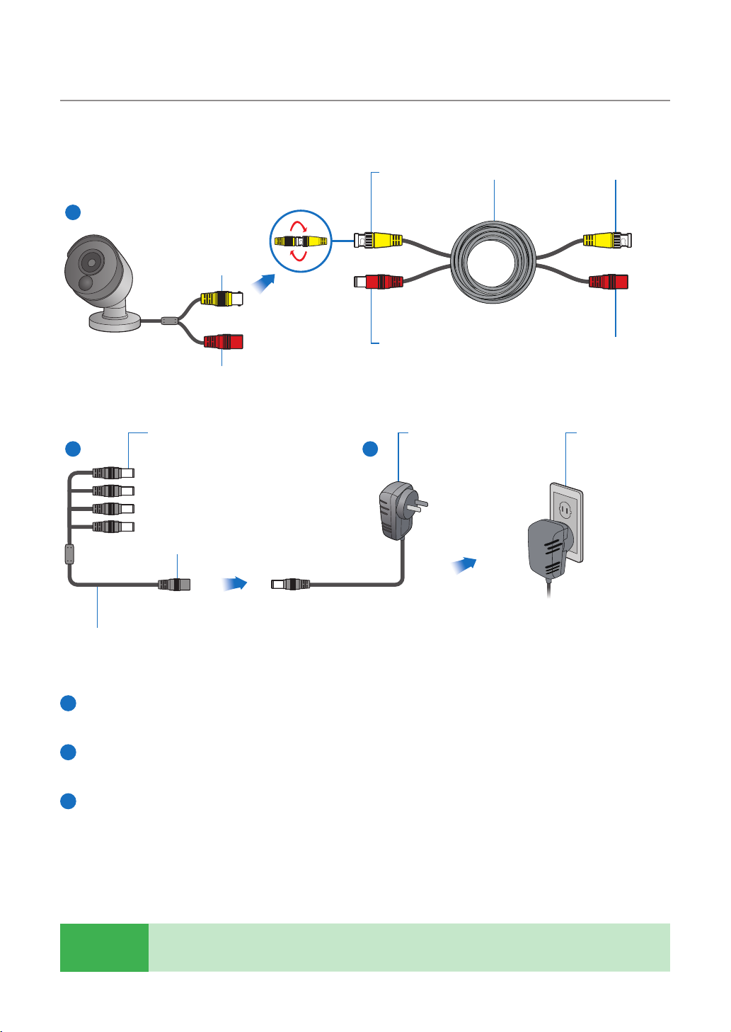
1.5 Mounting the cameras
Twist to lock
connectors
1
Video Output
Power Input
Video & Power Cable
2 3
connects here
Power Adapter
connects here
Video Input Video & Power Cable
Power Adapter
Connect this to the DVR
Power Splitter connects herePower Output
Connect to a spare
wall socket
Power Splitter
Connect the video output and power input connection on the camera to the corresponding connections on the
1
supplied video & power cable.
Connect the supplied power splitter to the other end of the video & power cable. This provides power to multiple
2
cameras using a single power adapter.
Connect the other end of the power splitter to the supplied power adapter then connect the power adapter to
3
a power outlet.
TIP
Each Homeguard camera is supplied with a mounting kit for attaching it to a wall. Before you affix the
camera in position, please ensure the cable is of adequate length to reach the DVR.
10

1.6 Using Remote Control
Part Names Functions
1-8
9, 0
ALL
Menu
Mute
Submenu
▲
Sel
◄►
▼
◄◄
►►
►
●
■
▌▌
Numeric keys. Press to display channel 1~8
Numeric keys
Press to display all channels. Multiple display mode
Press to enter or exit the Main Menu
Mute On/off
Go to submenu
Up arrow key; Volume increase
Press to enter the selected menu item and edit the setting
Left/Right key; Decrease/increase parameter value of control bar
Down arrow key; Volume decrease
Press to rewind during video playback
Press to fast forward during video playback
Press to play recorded video or enter the recording search menu
Press to start manual recording
Press to stop manual recording or stop the video playback
Press to pause the video playback or enter frame-playback mode
11
 Loading...