

Iget HGDVK-84408, HGDVK-44404, HGDVK-84402, HGDVK-84404, HGDVK-164408 Quick Start Manual
...Page 1
Helpdesk / Technical Support
www.iget.eu/cs/helpdesk-centrum-cs
https://helpdesk.intelek.cz/
Page 2

SMART
DETECTION
MOTION & HEAT TRIGGER ACCURATE ALERTS
H
eat-sensing HD CCTV Kit
Quick Start Guide - EN
For the latest, up-to-date manual, please visit
www.iget.eu
Page 3
CAUTION
RISK OF ELECTRIC SHOCK
DO NOT OPEN
TO REDUCE THE RISK OF ELECTRIC SHOCK,
DO NOT REMOVE THE COVER.
NO USER SERVICABLE PARTS INSIDE.
REFER SERVICING TO QUALIFIED PERSONNEL.
The lightning flash with arrowhead symbol, within an equilateral triangle, is intended to alert
the user to the presence of non-insulated “dangerous voltage” within the product’s enclosure
that may be of sufficient magnitude to constitute a risk of electric shock.
The exclamation point within an equilateral triangle is intended to alert the user to the
presence of important operating and maintenance (servicing) instructions in the literature
accompanying the appliance.
1
WARNING:
CAUTION:
TO PREVENT FIRE OR SHOCK HAZARD, DO NOT
EXPOSE THIS UNIT TO RAIN OR MOISTURE
TO PREVENT ELECTRIC SHOCK, ENSURE THE PLUG
IS FULLY INSERTED INTO A MAINS SOCKET
Page 4

IMPORTANT SAFEGUARD
All lead-free products offered by the company comply with the requirements of the
RoHS
conform
European law of the Restriction of Hazardous Substances (RoHS) directive, which means
our manufacturing processes and products are strictly “lead-free” and without the
hazardous substances cited in the directive.
The crossed-out wheeled bin mark symbolizes that within the European Union the
product must be collected separately at the product’s end-of-life. This applies to your
product and any peripherals marked with this symbol. Do not dispose of these products
as unsorted municipal waste. Contact your local dealer for procedures for recycling this
equipment.
DISCLAIMER
We reserve the right to revise or remove any content in this manual at any time. We do not warrant or assume any
legal liability or responsibility for the accuracy, completeness, or usefulness of this manual. The content of this
manual is subject to change without notice.
RECOMMENDATIONS
• AVOID DUSTY LOCATIONS:
• INSTALL IN VENTILATED SPACE:
• DO NOT EXPOSE TO MOISTURE:
• DO NOT DROP:
• DO NOT OPEN CHASSIS:
Excessive build-up of dust may cause the unit to fail.
Ensur
e adequate airflow around the DVR to prevent overheating.
Exposing the unit to water poses high risk of electric shock.
Doing so could damage internal components.
No user-serviceable parts inside.
TRADEMARKACKNOWLEDGEMENTS
• Internet Explorer™, Microsoft™&Windows™ are registered trademarks of Microsoft Corporation.
• Apple™, iPhone™, iPad™ and iTunes™ are registered trademarks of Apple Computer, Inc.
• AndroidTM and Google Play™ are registered trademarks of Google Inc
WARRANTY AND TECHNICAL SUPPORT
To help you make the most of this product you’ll find a host of information including full product manuals, FAQ,
troubleshooting guides and a support service if you have specific questions, available at our support website :
homeguardworld.com/support.
2
Page 5

CONTENTS
CONNECTING YOUR SYSTEM
4
BASIC OPERATION
13
5
Introduction
6
Package Contents
7
DVR Layout
9
Connecting the DVR
10
Mounting the Cameras
11
Using Remote Control
12
Using the Mouse
14
Start-up Wizard
17
Main Interface
19
PIR Setup
20
Record
21
Playback
CONNECTING SMART DEVICE
22
CONNECTING TO PC&MAC
28
TECHNICAL SUPPORT
36
23
Before Start
23
Get the App
24
User Interface
25
For iPhone
26
For iPad
27
For Android Phone
29
Homeguardsafe Software for PC & Mac
32
Remote Access via Web Client
35
Cloud Access
37
Technical Specifications
38
Technical Q&A
39
Warranty & Support
40
Camera Installation Template
3
Page 6

CONNECTING
YOUR SYSTEM
1
4
Page 7

1.1 Introduction
Congratulations on your purchase of this Homeguard Hybrid DVR. Homeguard offers a complete CCTV solution for
home or office security, featuring high quality cameras, easy setup and configuration, motion detection and network
connectivity.
This system features:
• H.264 Video compression and G.711 audio compression
• Support CVBS, AHD, TVI, CVI and IPC
• Provides a convenient User Interface
• 4/8 CH Composite Input Connectors
• Supports 1080p/720p/960H/D1/CIF recording formats
• With the network specific codec, network transfer enabled regardless of the recording conditions
• Hard Disk overwrite function
• Mass storage hard disk backup through high-speed USB 2.0
• Simultaneous Record and Playback of 4/8/16-channel video data
• Various Search Modes (Search by Time, Event, Backup and Motion Detection)
• Various Recording Modes (Manual, Scheduled Recording)
• Remote Monitoring function by Network Viewer and Mobile Viewer
5
Page 8
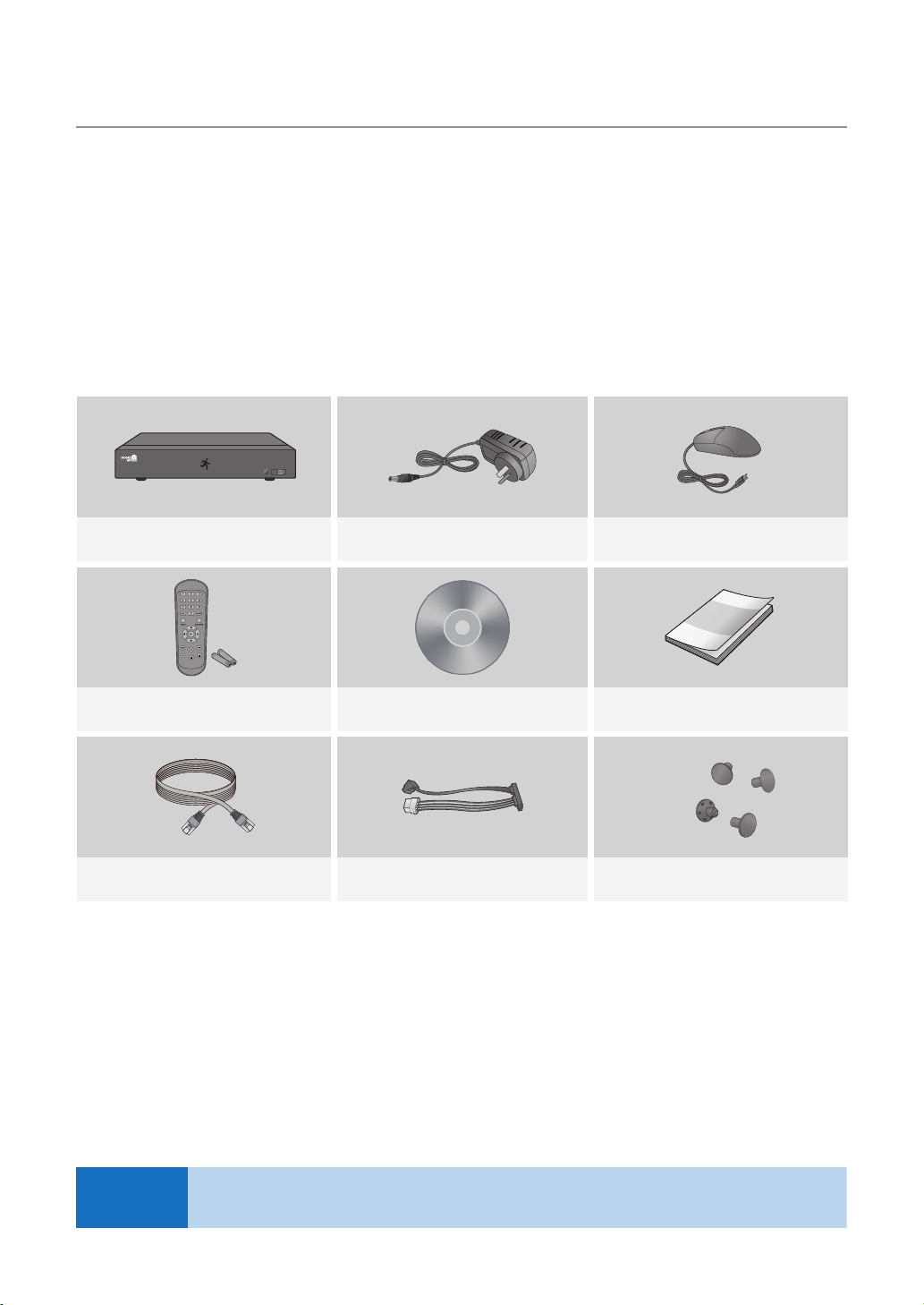
1.2 Package Contents
Please unwrap the product, and place the product on a flat place or in the place to be installed.
Please check the following contents are included in addition to the main unit.
• The appearance of the components may differ from the image shown.
• Accessory category and quantity may differ depending on sales region.
Check the contents of your DVR package against this checklist. If anything is missing or damaged, please do not use
the system, and inform your supplier as soon as possible.
HDD NET PWR
1080P HD DIGITAL VIDEO RECORDER
Hybrid DVR Power Adapter Mouse
USB
NOTE
User Manual / SoftwareRemote Control / Battery (AAA x 2) Quick Start Guide
Ethernet Cable
SATA Cable
(for models having no installed HDD)
This manual covers both 4 channel and 8 channel versions of the Homeguard DVR kits model:
HGDVK-44402 / 44404 / 84402 / 84404 / 84408 / 164408 / 164416.
HDD Fixing Screw
6
Page 9
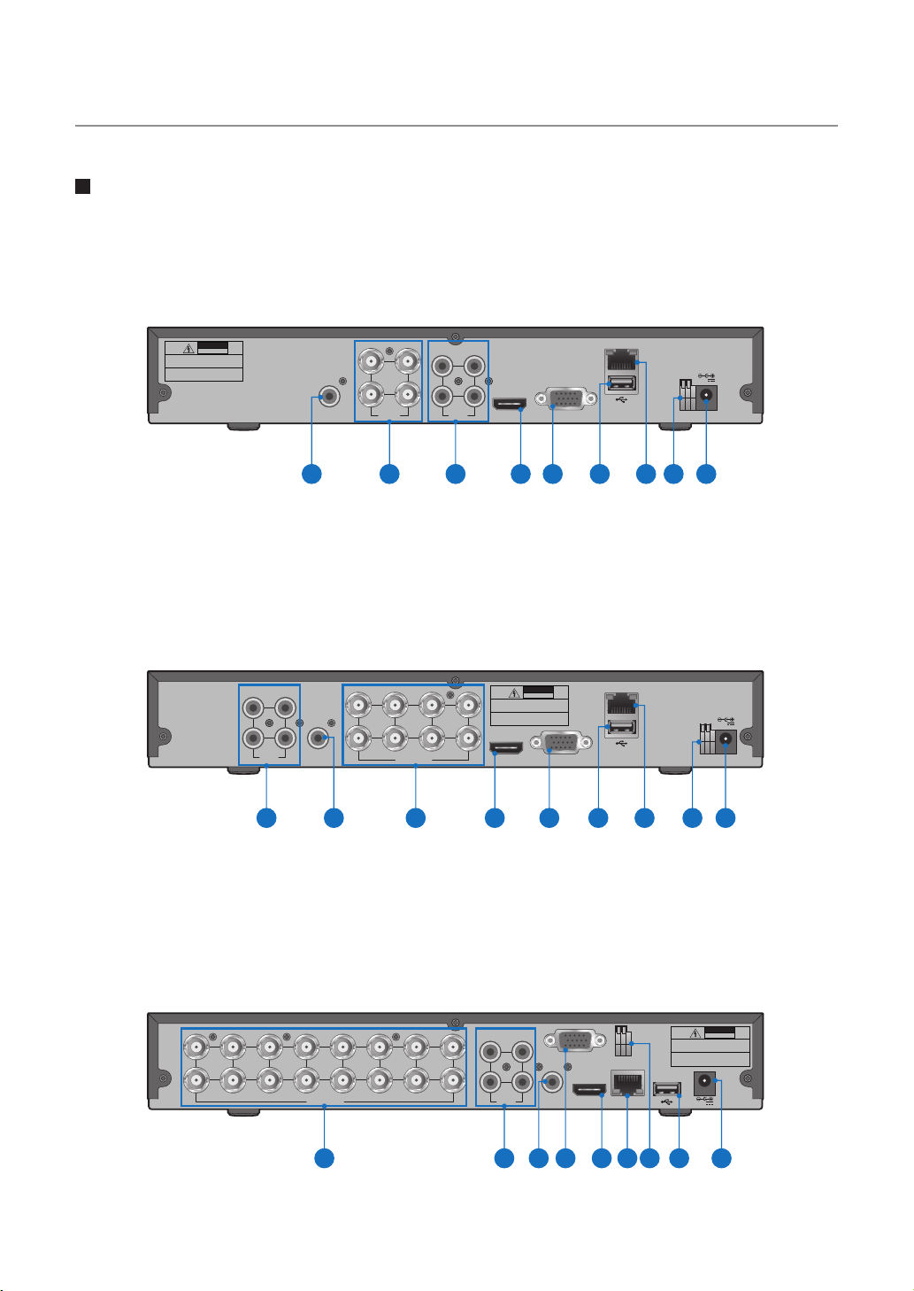
1.3 DVR Layout
Rear Panel
4CH DVR
DVR Kits Model: HGDVK-44402 / 44404
CAUTION
RISK OF ELECTRIC SHOCK
DO NOT OPEN
CAUTION : TO REDUCE THE RISK OF ELECTRICAL SHOCK
DO NOT OPEN COVERS. NO USER SERVICEABLE
PARTS INSIDE. REFER SERVICING TO QUALIFIED
SERVICE PERSONNEL.
WARNING : TO PREVENT FIRE OR SHOCK HAZARD. DO NOT
EXPOSE UNITS NOT SPECIFICALLY DESIGNED
FOR OUTDOOR USE TO RAIN OR MOISTURE.
AUDIO
OUTPUT
1 2 3 4 5 6 7 8 9
8CH DVR
DVR Kits Model: HGDVK-84402 / 84404 / 84408
31
2 4
AUDIO
INPUT
2 8
AUDIO
OUTPUT
1 23 4 5 6 7 8 9
3 1
4 42 2
VIDEO
INPUT
3
1
4
VIDEO INPUT
AUDIO
INPUT
5 7
6
13
HDMI VGA
CAUTION : TO REDUCE THE RISK OF ELECTRICAL SHOCK
DO NOT OPEN COVERS. NO USER SERVICEABLE
PARTS INSIDE. REFER SERVICING TO QUALIFIED
SERVICE PERSONNEL.
WARNING : TO PREVENT FIRE OR SHOCK HAZARD. DO NOT
EXPOSE UNITS NOT SPECIFICALLY DESIGNED
FOR OUTDOOR USE TO RAIN OR MOISTURE.
HDMI VGA
CAUTION
RISK OF ELECTRIC SHOCK
DO NOT OPEN
LAN
+ -
12V
RS485
LAN
+ -
12V
RS485
16CH DVR
DVR Kits Model: HGDVK-164408 / 164416
11
13
15
14
16
7
VIDEO INPUT
CAUTION
RISK OF ELECTRIC SHOCK
13
AUDIO
OUTPUT
VGA
+ -
RS485
HDMI
LAN
1
3
5
7
9
2
4
6
8
1012
4 2
AUDIO
INPUT
DO NOT OPEN
CAUTION : TO REDUCE THE RISK OF ELECTRICAL SHOCK
DO NOT OPEN COVERS. NO USER SERVICEABLE
PARTS INSIDE. REFER SERVICING TO QUALIFIED
SERVICE PERSONNEL.
WARNING : TO PREVENT FIRE OR SHOCK HAZARD. DO NOT
EXPOSE UNITS NOT SPECIFICALLY DESIGNED
FOR OUTDOOR USE TO RAIN OR MOISTURE.
12V
132 5 4 7 68 9
Page 10
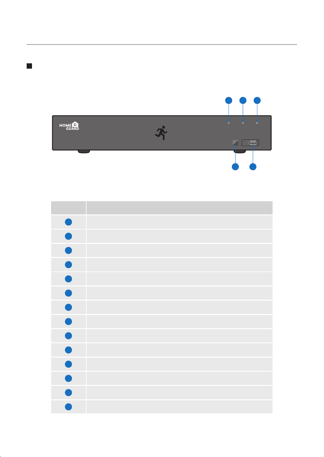
Front Panel
10 11 12
HDD NET PWR
1080P HD DIGITAL VIDEO RECORDER
Part Names Functions
1
2
3
4
5
6
7
8
RCA Audio Output: For speakers
4x / 8x / 16x BNC Video Connectors: For each camera input
4x RCA Audio Connectors: For each audio input*
HDMI Output: For most modern TVs
VGA Output: For most monitors
USB Ports: For USB mouse and external storage
LAN Port: To connect your DVR to the network
RS485: Connect to PTZ devices
USB
13 14
9
10
11
12
13
14
Power Connector: To power the DVR
HDD LED: Flashes when the HDD is in use
Network LED: Flashes when the internet is connected
Power LED: Indicates the DVR is turned ON when lit
IR Receiver: Receives the signal from the remote control
USB Ports: For USB mouse and external storage
8
Page 11
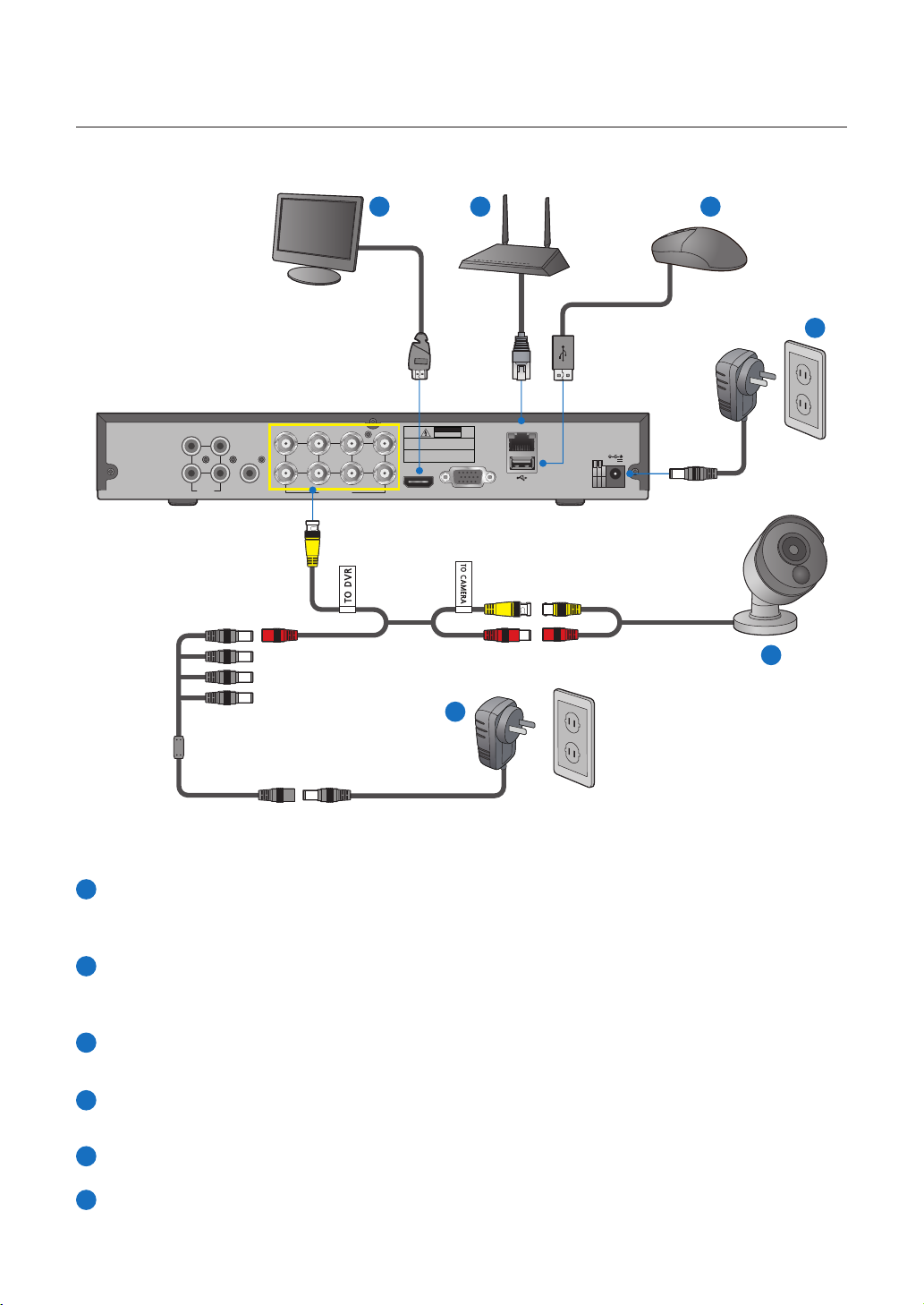
1.4 Connecting the DVR
53 4
6
LAN
+ -
12V
RS485
2 4
AUDIO
INPUT
5 7
31
AUDIO
OUTPUT
341
VIDEO INPUT
6
2 8
CAUTION
RISK OF ELECTRIC SHOCK
DO NOT OPEN
CAUTION : TO REDUCE THE RISK OF ELECTRICAL SHOCK
DO NOT OPEN COVERS. NO USER SERVICEABLE
PARTS INSIDE. REFER SERVICING TO QUALIFIED
SERVICE PERSONNEL.
WARNING : TO PREVENT FIRE OR SHOCK HAZARD. DO NOT
EXPOSE UNITS NOT SPECIFICALLY DESIGNED
FOR OUTDOOR USE TO RAIN OR MOISTURE.
HDMI VGA
1
2
Connect the camera's video input (yellow) and power supply (red) connectors to the BNC extension cables. Then
1
connect the BNC video input (yellow) to the video input port on the rear panel. (Repeat Step 1 for the remaining
cameras.)
Connect the camera's power supply (red) to the power splitter. Then connect the other end of the power splitter
2
to the power adapter for Cameras and plug in the adapter to a wall outlet. (Repeat Step 2 to connect the cameras to the second set of power splitter and power adapter.)
Depending on the monitor port, connect the HDMI or VGA cable from your monitor to the HDMI or VGA Port on
3
the rear panel.
Connect one end of the Ethernet cable into your router’s LAN port, and the other end of the cable to the Ethernet
4
port on the rear panel.
5
Connect the mouse to the USB Port on the front or back panel of the DVR.
Connect the power adapter for DVR to the DC 12V port on the rear panel and the power plug into a wall outlet.
6
The DVR will automatically power on and the startup wizard will appear on your monitor.
9
Page 12
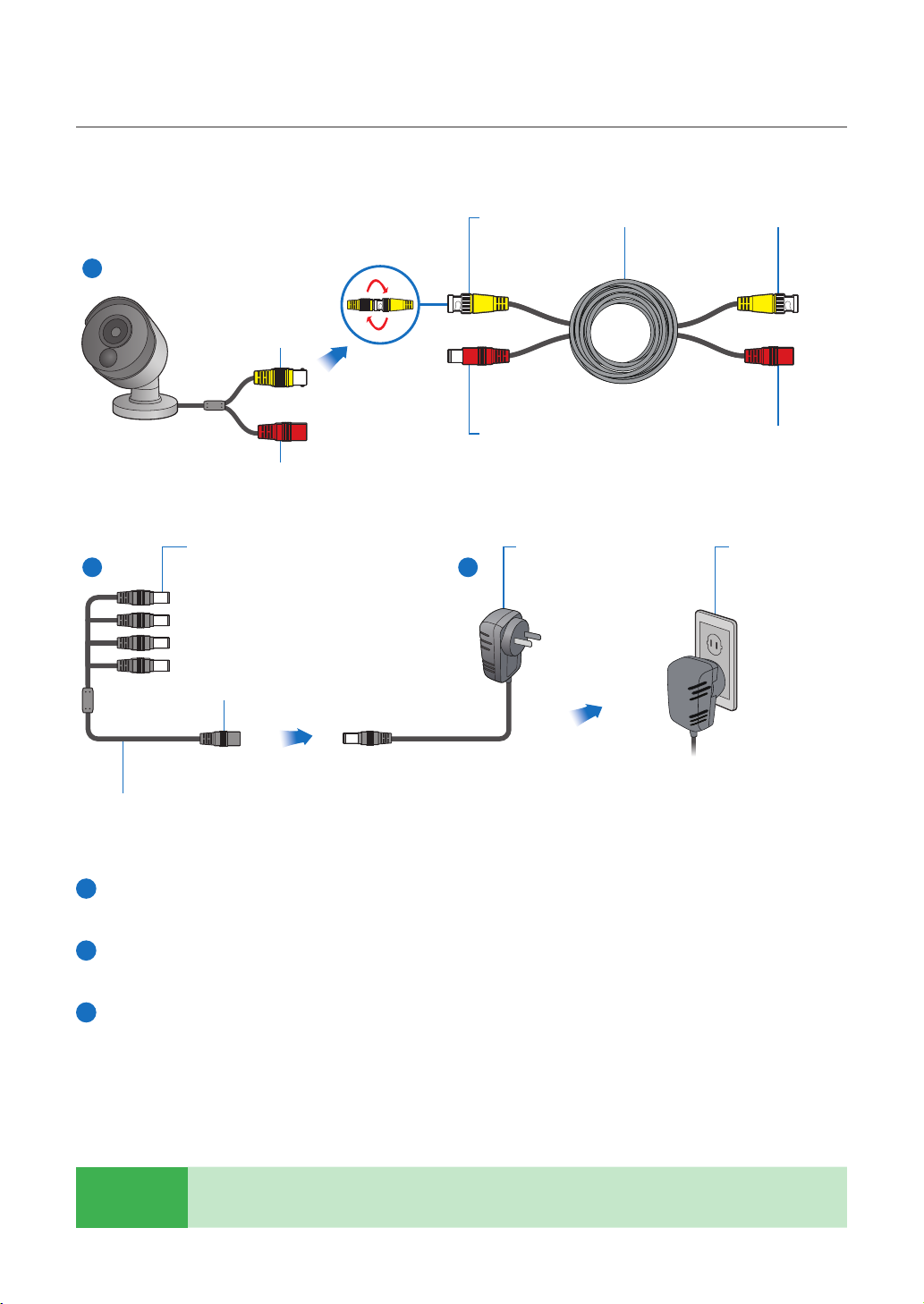
1.5 Mounting the cameras
Twist to lock
connectors
1
Video Output
Power Input
Video & Power Cable
2 3
connects here
Power Adapter
connects here
Video Input Video & Power Cable
Power Adapter
Connect this to the DVR
Power Splitter connects herePower Output
Connect to a spare
wall socket
Power Splitter
Connect the video output and power input connection on the camera to the corresponding connections on the
1
supplied video & power cable.
Connect the supplied power splitter to the other end of the video & power cable. This provides power to multiple
2
cameras using a single power adapter.
Connect the other end of the power splitter to the supplied power adapter then connect the power adapter to
3
a power outlet.
TIP
Each Homeguard camera is supplied with a mounting kit for attaching it to a wall. Before you affix the
camera in position, please ensure the cable is of adequate length to reach the DVR.
10
Page 13
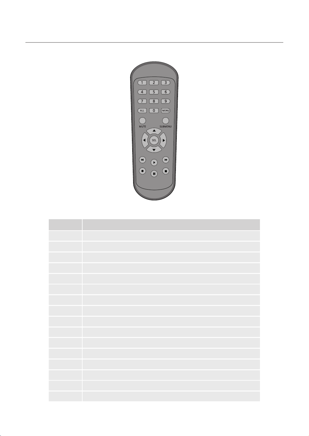
1.6 Using Remote Control
Part Names Functions
1-8
9, 0
ALL
Menu
Mute
Submenu
▲
Sel
◄►
▼
◄◄
►►
►
●
■
▌▌
Numeric keys. Press to display channel 1~8
Numeric keys
Press to display all channels. Multiple display mode
Press to enter or exit the Main Menu
Mute On/off
Go to submenu
Up arrow key; Volume increase
Press to enter the selected menu item and edit the setting
Left/Right key; Decrease/increase parameter value of control bar
Down arrow key; Volume decrease
Press to rewind during video playback
Press to fast forward during video playback
Press to play recorded video or enter the recording search menu
Press to start manual recording
Press to stop manual recording or stop the video playback
Press to pause the video playback or enter frame-playback mode
11
Page 14

1.7 Using the Mouse
1 2
3
1
Left Button:
• Click to select menu options.
• During live viewing in split-screen view, double-click on a channel to view it in full-screen. Double-click the
channel again to return to split-screen viewing.
• Click upon a channel on Live Viewing screen to open Camera Quick Tool bar.
• Click and hold to drag sliders and scales on menu mode
2
Right Button:
• Click once to open the Task bar on the Live Viewing screen.
• In menus, click to go back / close menus.
3
Scroll Wheel:
• In menus, scroll to move up / down through the menu content.
• While hovering over the volume control wheel, scroll to turn system volume up / down.
12
Page 15

BASIC
2
OPERATION
13
Page 16

2.1 Start-up wizard
1
Create a Password
Please create a user name and password
for your device. Password MUST be 8
characters long.
Use the on-screen keyboard to input text,
numbers and characters. Click to
change from lower-case to upper-case
2
Start Wizard
After DVR startup is completed, the start-up
wizard will be displayed. Click "Start
Wizard".
3
Network
In DHCP mode the router will automatically
assign an IP address to DVR.
If the DVR fails to obtain an IP address, refer
to the DVR Router Guide. If the problem
still cannot be resolved, contact technical
support.
CAUTION
Don’t forget to write down your password: ___ ___ ___ ___ ___ ___ ___ ___.
14
Page 17

4
Date / Time
Set the date, time, NTP, DST.
5
Disk
New hard drive(s) connected must be
formatted before use. Upon connection, it
will indicate to format new hard drive.
Click on "Select" to select the unformatted
hard drive. Click on "Format HDD" to pop
up the user login window and enter the
password to log in. A notice window will
indicate "Entire Data Will Be Erased. do
You Want To Continue?". Click "OK" to
format the disk. When the progress bar is
complete, the formatting process is
completed.
6
Resolution
Select the resolution for the VGA output or
HDMI output of your monitor.
15
Page 18

7
Mobile
If you scan a QR code using Homeguardsafe,
the device ID displayed in the DVR will be
automatically reflected in the Mobile Viewer
ID, and you can use the Mobile Viewer
immediately by entering the ID / password
of the DVR.
8
Summary
Shows system and network status of DVR.
Click on “Finish” to finish setting of startup wizard.
9
You can click on “Don’t show this window next time” if you do not wish to have the wizard setting to appear
next time.
16
Page 19

2.2 Main Interface
1
4 5 6 7 8 9
21
22
23
24
25
20
32
11 12 13 14 15 16 17 18 19
10
Part NamesItems Functions
1
2
3
4
5
6
7
8
9
Channel Name
PIR
Motion Detection
Manual Recording
Manual Capture
Instant Playback
PTZ
Zoom
Color Setting
Display channel name
This icon appears when the camera has PIR detection
This icon appears when the camera has detected motion
Enable or disable manual recording
Make a snapshot of current video
Playback of the last five minutes of the video
Click to enter PTZ control panel
Hold and drag mouse cursor to select a frame of current video to zoom in
Set hue, brightness, contrast and saturation of current channel
17
Page 20

Part NamesItems Functions
10
11
12
13
14
15
16
17
18
19
20
21
Main Menu
4-Channel Layout
More Layout
Auto SEQ
Play
Audio
Stream Switch
Preview Policy
Connection State
Manual Mode
System
Video Loss
Admin
Access the main menu
Display four channels of video
Click to choose more layouts for live view
Press this button to switch the screen mode in sequence
Replay video recorded
Click to adjust audio volume
Click to switch all IP channels between main stream and sub stream
Click to switch among real-time, balanced, or smooth view
Display the network connection status
Set manual recording mode
System Information
Camera is off-line
To switch user
22
23
24
25
Search
Setup
Lock Screen
Shutdown
Search & Playback
Click to access DVR System Setup menu
Lock & unlock screen
Shutdown, reboot & logout the system
18
Page 21

2.3 PIR Setup
PIR is advanced motion detection that senses body heat and reduces false alarms. The PIR Technology takes your
motion detection to the next level by greatly reducing inaccuracies and false motion alerts. Homeguard camera’s PIR
sensor can detect changes in heat produced by humans, animals and vehicles. This new technology requires both
changes in motion and heat be detected simultaneously. Not only does this innovative technology significantly reduce
the number of false alerts you receive, it also conserves hard drive space. It is true and smart detection!
Access Main menu Setup Channel
1
PIR.
Click Setup button to set the PIR detect
2
field.
click “Select all” to set all of the field. Right
2
click and exit, then click “Apply” to save the
setting.
19
Page 22

2.4 Record
Access Main menu Setup Record
1
Record
2
Record
Record Switch: Check to enable the recording
in this channel.
Stream Mode: Choose the recording quality.
If you choose Dualstream, the system will record
in both Mainstream & Substream.
PreRecord: If this option is enabled, the DVR
starts recording a few seconds before an alarm
event occurs. Use this option if your primary
recording type is motion or I/O alarm based.
3
Record Schedule
This menu allows you to specify when the DVR
records video and defines the recording mode
for each channel. The recording schedule lets
you set up a schedule like, daily and hourly by
normal (continuous) recording, motion recording, PIR recording. To set the recording mode,
click first on the mode radio button (Normal,
Motion, PIR), then drag the cursor to mark the
slots.
20
Page 23

2.5 Playback
Click Search button in the Main Menu to enter search / playback section.
1
2
3
4
5
7
6
Part NamesItems Functions
1
Search Options
The system provides various search & playback methods: General, Events,
Sub-periods, Smart & Pictures
21
2
3
4
5
Search Date
Search Type
Channel Selection
Video Playback Controls
Search by a date to play back.
The system provides different search types to narrow your search.
To choose the channels you want to search & play.
To control the video playback.
Continuous recordings are shown with colored bars to represent different types
6
Timeline
of recording (legend shown in the bottom-right corner of the display). Use the
timeframe options.
7
Playback Status
Display the video play status.
Page 24

CONNECTING
SMART DEVICE
3
22
Page 25

3.1 Before Start
• Make sure you have a router and high-speed Internet access (not included).
• Connect your DVR to your router using an Ethernet cable (see the Quick Connection
Guide for details).
• Upgrade your DVR firmware and client software or mobile app to the latest versions.
• Please note that an upload speed of 1Mbps is required for remote video streaming.
• Up to 3 devices may connect to the system at the same time.
3.2 Get the App
For the best experience, download the Homeguardsafe app for your smartphone by scanning the QR code below or
searching for “ Homeguardsafe ” in the App Store or Google play.
23
iOS - iPhone & iPad
Android - Phone & Pad
Page 26

3.3 User Interface
1
2
3
1 2
Live View
Displays real-time footage of
your system.
Playback
Play video that has been
recorded on your DVR.
3
Smart Detection
Access the Smart Detection
notification list and to
enable push notifications.
24
Page 27

3.4 For iPhone
Install the free Homeguardsafe app from the App Store. Tap the Homeguardsafe icon
1
to open the app.
After start app, tap to open device
2
list page, click “+” to add a new device.
3
Tap to scan QR code, then enter the password of DVR.
HDD NET PWR
1080P HD DIGITAL VIDEO RECORDER
4
Tap “Save” to add DVR. The app opens in Live View and streams video from all connected cameras.
USB
25
Page 28

3.5 For iPad
Install the free Homeguardsafe app from the App Store. Tap the Homeguardsafe icon
1
to open the app.
After start app, tap to open
2
device list page, click “+” to add a
new device.
Tap to scan QR code, then
3
enter the password of DVR.
HDD NET PWR
1080P HD DIGITAL VIDEO RECORDER
4
Tap “Save” to add DVR. The app opens in Live View and streams video from all connected cameras.
USB
26
Page 29

3.6 For Android
Install the free Homeguardsafe app from the Google Play. Tap the Homeguardsafe icon
1
to open the app.
After start app, tap to open device list
2
page, click “+” to add a new device.
3
Tap to scan QR code, then enter the password of DVR.
HDD NET PWR
1080P HD DIGITAL VIDEO RECORDER
4
Tap “Save” to add DVR. The app opens in Live View and streams video from all connected cameras.
USB
27
Page 30

CONNECTING
TO PC&MAC
4
28
Page 31

4.1 Homeguardsafe Software for PC & Mac
Find the setup file of digital surveillance central management software named
1
“Homeguardsafe” from CD, and install it.
Double left click the icon to pop up [ LOGIN ]
2
interface, Input your user name & password
you like, and click “Login” to enter the
system.
Run Homeguardsafe and Add Device Wizard
3
will be opened. Click Next.
Note: If Add Device Wizard is not opened,
please single click Help to manually open it.
Click Add Online Device and the client
4
software will scan all the online network
DVRs in LAN.
29
Page 32

Click a DVR in the list and the added devices,
5
IP address, port and channel number will be
displayed. Click Add Selected Device to add.
Note: If your DVR is not available in the list,
click Exit and then click add Device to manually
input the IP address of DVR.
Input the name of the selected DVR, e.g. home,
6
office, etc. Input the DVR user name and
password. Click Add.
Click Import All to import all DVRs to the
7
default group.
Click Next and then click Finish to complete
the wizard.
30
Page 33

Click Control Panel option. Then Click
8
Main View.
Click and drag the default group to the display
9
window to access real-time footage of your
system.
31
Page 34

4.2 Remote Access via Web Client
For IE/Chrome/Firefox
Launch the explorer on your PC and enter the DVR IP address or DDNS domain name (Host Name) you have
1
set on DVR in the URL box.
For the first time you run the web client,
2
system will require to install the web client
plugin.
Click download to download the plugin
and install to your computer.
After installing the plug-in, close & launch
3
again your browser and repeat step 1 to
open the login page. Input your user name
and password to login the web client.
32
Page 35

For Mac Safari
Launch the Safari in your Mac, and enter
1
the DVR IP address or DDNS domain
name (Host Name) you have set on DVR
in the URL box.
Download the plug-in
2
"SurveillanceClient.dmg", locate the
downloaded file and double click it.
Click on “Continue” “Install”. Enter user
3
name and password for Mac computer,
Click on “Install Software” “Close” to
finish installation.
4
Close Safari and open again to repeat step 1 to open the Web Client login page.
33
Page 36

Live Interface
2 3
1
9
11
Items Functions
4 5
6
7
8
10
1
Channel List
2
Live Video Stream Options
3
Main Menus
4
Information: Hover over to see system details
5
Exit
6
Color Controls: Click to display or hide the color controls
7
PTZ Controls: Click to display or hide the PTZ controls for using PTZ cameras
8
PTZ Controls: PTZ control menu
9
Live View Control Buttons
10
11
Navigation: Shows current page number for the channels shown on screen. Use the arrow keys to switch between pages
Page View: Click to select how many channels appear on screen at a time
34
Page 37

4.3 Homeguard Cloud Access
Open your browser, go to
1
www.homeguardsafe.com
Please sign up and login.
Click Device Manager, input the device
2
information and click save to add DVR.
Click Live, Click ► to Displays real-time
3
footage of your system.
Click Playback, you can play video that
4
has been recorded on your DVR.
35
Page 38

TECHNICAL
SUPPORT
5
36
Page 39

5.1 Technical Specifications
Homeguard Hybrid DVR
Compression
Operating System
Smart Device Support
Dual Stream
Image Quality
Frame Rate Recording
Image Playback Quality
Video Mode
Backup Capability
User Control
Signal Input
H.264 Standard Compression
Linux
Apple iOS(iPhone/iPad) and Android Phones and Tablets
Yes, Set by Channel
1080p (1920 × 1080)
4 Channel: 1080p 15fps per Channel
8 Channel: 1080p 15fps per Channel
16 Channel: 1080p 15fps per Channel
1080p 4 Channel DVR: 60fps (15fps for 4 Channels)
1080p 8 Channel DVR: 120fps (15fps for 8 Channels)
1080p 16 Channel DVR: 240fps (15fps for 16 Channels)
Manual, Automatic & Motion Detection
USB Devices (Hard Disk, Flash Drive, DVD/RW etc.),
Webpage, CMS, Mobile Client
Mouse or Remote Control (Both Included)
CVBS, TVI, AHD, CVI, IP (optional), 5 in 1 Hybrid DVR
Video Input
Video Output
Audio Input
Audio Output
Network Interface
USB Port
RS485
Alarm Input / Output
Interface
Power
Operating Temperature
DVR Size
37
4 Channel: 4 × BNC
8 Channel: 8 × BNC
16 Channel: 16 × BNC
1 × VGA, 1 × HDMI
4 × RCA
1 × RCA, 1 × HDMI
100M Ethernet (RJ-45)
2 × USB 2.0
1 × RS485
No Alarm Input or Output, Not Supported
1 × SATA HDD, Maximum Support to 6TB
12V/2A
-10˚C ~ 55˚C
300 × 208 × 53mm
Page 40

5.2 Technical Q&A
01: The DVR doesn’t start once the power supply is connected
Please check the power switch at the rear panel of DVR.
Please check the power supply you are using is rated 12V/2A or above.
02: The DVR turns on but stays at the welcome screen
The hard drive may be faulty
The software may be corrupted.
03: The DVR is very slow to start
It may be that the hard drive is nearly full, causing the system to search for longer for the files required
A hard drive error can cause this delay.
04: The system reboots repeatedly
Check the hard drive is formatted to FAT32
Check the power supply is of the correct rating
Disconnect the network cable and check if the DVR becomes stable.
05: The DVR stops during playback
Check the hard drive is working correctly
Check the DVR is not getting too hot
Check there are no external electrical devices drawing too much current near the DVR.
06: The firmware upgrade has failed
Check the USB drive used is compatible with the DVR
USB interface is faulty.
07: The picture displayed is black and white
Check the video parameters are matching between you DVR and TV or monitor.
08: There is no image displayed
Ensure your TV or Monitor is switched on and the image properties are correct (brightness, etc)
Check that the video cables are properly connected.
09: The video is distorted
Check for damage on the video cable
If the video is obstructed by interference, select a shielded cable
Ensure only one grounding point is selected on the DVR.
10: The colours displayed are distorted
Check the video parameters are correct
Check the camera connection is good.
11: The video is skewed or deformed
Make sure the VGA cable and DVR are connected with grounding properly;
Make sure the DVR is not too hot.
12: The playback quality is poor
The recording parametersare set too low
The video files are locatedon a bad sector of the hard drive.
38
Page 41

5.3 Warranty & Support
All the products sold are covered by 24 months warranty from the date of invoice.
Warranty instructions:
1. Please contact us when the product is caused by its own fault within 2 year warranty.
2. Please mail us your written warranty card as soon as possible after purchasing our products so that we can repair
or replace this product to its original operation condition. Or the company will not deal with it.
3. Please write the truth on the warranty card.
4. Paid for repairing as follows:
A. Equipment failure caused by human operation
B. Equipment failure caused by not conforming to the using environment
C. No warranty card
D. Warranty expired
Product model:
Product serial number:
Purchase date:
User name:
Contact person:
Telephone:
24
39
Note: Please keep the warranty card for the better service.
Technical support
www.iget.eu/cs/helpdesk-centrum-cs
https://helpdesk.intelek.cz/
Page 42

5.4 Camera Installation Template
To make camera installation easier, you can tear off this page and adhere it to the place you would like to install
your cameras.
TEMPLATE
This template is used to install the camera on the wall
CAMERA FRONT
40
 Loading...