

Page 1
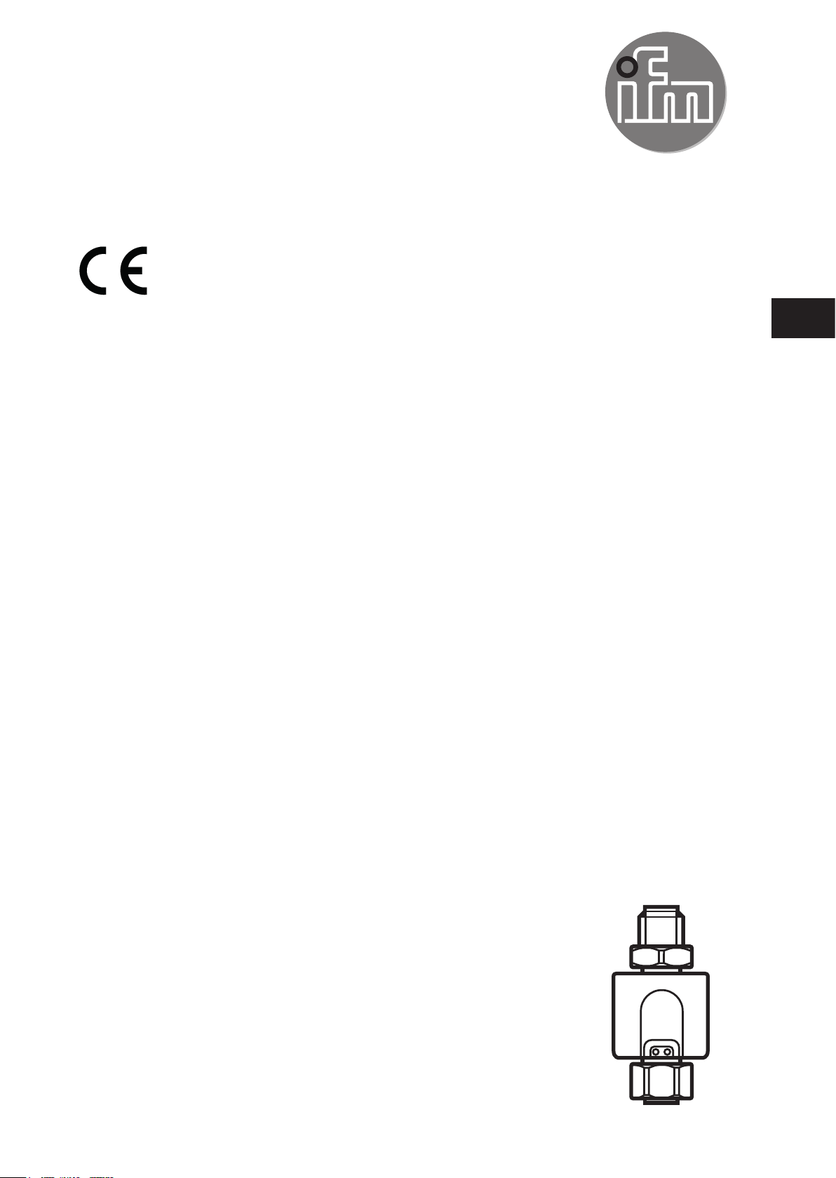
Operating instructions
Measured signal converter
for temperature sensors
TP323x
UK
704899 / 00 07 / 2019
Page 2

Contents
1 Preliminary note ��������������������������������������������������������������������������������������������������� 2
1�1 Symbols used ������������������������������������������������������������������������������������������������2
2 Safety instructions �����������������������������������������������������������������������������������������������3
3 Functions and features ����������������������������������������������������������������������������������������3
4 Function ��������������������������������������������������������������������������������������������������������������� 4
4�1 IO-Link �����������������������������������������������������������������������������������������������������������4
5 Installation������������������������������������������������������������������������������������������������������������4
6 Electrical connection �������������������������������������������������������������������������������������������� 5
7 Parameter setting ������������������������������������������������������������������������������������������������6
7�1 Adjustable parameters ����������������������������������������������������������������������������������� 6
8 Operation ������������������������������������������������������������������������������������������������������������� 7
9 Technical data and scale drawing ������������������������������������������������������������������������ 7
10 Factory setting ���������������������������������������������������������������������������������������������������7
1 Preliminary note
1.1 Symbols used
► Instruction
> Reaction, result
→ Cross-reference
Important note
Non-compliance can result in malfunction or interference�
2
Page 3

2 Safety instructions
• The device described is a subcomponent for integration into a system�
- The manufacturer of the system is responsible for the safety of the system�
- The system manufacturer undertakes to perform a risk assessment and to
create a documentation in accordance with legal and normative requirements
to be provided to the operator and user of the system� This documentation
must contain all necessary information and safety instructions for the operator,
the user and, if applicable, for any service personnel authorised by the
manufacturer of the system�
• Read this document before setting up the product and keep it during the entire
service life�
• The product must be suitable for the corresponding applications and
environmental conditions without any restrictions�
• Only use the product for its intended purpose (→ Functions and features).
• If the operating instructions or the technical data are not adhered to, personal
injury and/or damage to property may occur�
• The manufacturer assumes no liability or warranty for any consequences
caused by tampering with the product or incorrect use by the operator�
• Installation, electrical connection, set-up, operation and maintenance of the unit
must be carried out by qualified personnel authorised by the machine operator�
• Protect units and cables against damage�
UK
3 Functions and features
In connection with a temperature probe the unit monitors the system temperature
in machines and plants�
Connectable temperature probes:
• Temperature sensors TM, TS, TT�
• Resistance thermometer RTD (Pt 100 or Pt 1000).
The unit detects the connected sensor type and configures itself accordingly�
3
Page 4

4 Function
• The unit converts the measured signal into a temperature-proportional
analogue signal: 4���20 mA at [OU2] = [I] / 20���4 mA at [OU2] = [Ineg]�
• The analogue signal can be scaled� Factory setting → 10�
Minimum distance between ASP (analogue start point) and AEP (analogue end
point) = 5 °C or 9 °F.
• The unit supports IO-Link�
4.1 IO-Link
This unit has an IO-Link communication interface which enables direct access to
process and diagnostic data� In addition it is possible to set the parameters of the
unit while it is in operation� Operation of the unit via an IO-Link interface requires
an IO-Link master�
With a PC, suitable IO-Link software and an IO-Link adapter cable communication
is possible when the system is not in operation�
The IODDs necessary for the configuration of the unit, detailed information about
process data structure, diagnostic information, parameter addresses and the
necessary information about the required IO-Link hardware and software can be
found at www�ifm�com�
5 Installation
► Connect the unit to a temperature
1
probe�
2
1: Connection for voltage supply and output signals
2: Connection for temperature probe
4
Page 5

6 Electrical connection
The unit must be connected by a qualified electrician�
The national and international regulations for the installation of electrical
equipment must be adhered to�
Voltage supply to EN 50178, SELV, PELV�
► Disconnect power�
► Connect the unit as follows:
2
3
1
4
1
1
2
L
L
+
2
2
4
3
1
+
L
L
IO-Link
L
UK
1
2
3
1 432 432
3 4
1
LED1
4
LED2
1 / 2: Connection Ub and output signals
Pin 1 L+
Pin 3 L-
Pin 4 (OUT1) IO-Link
Pin 2 (OUT2) Analogue signal for temperature
3: Connection of a 2-wire measuring probe;
links between 1 / 2 and 3 / 4� A wire fault can be corrected in the menu COF�
4: Connection of a 4-wire measuring probe�
LED 1: lit in case of operation as 3-wire unit, IO-Link communication is possible�
LED 2: lit in case of a load on the analogue output�
5
Page 6

7 Parameter setting
Using an IO-Link capable parameter setting tool, the following options are
available:
- Reading current process values�
- Reading, changing and saving current parameter settings and transmitting
them to other units of the same type�
7.1 Adjustable parameters
OU2
ASP
AEP
COF
FOU2
Output function for OUT2:
Analogue signal: 4���20 mA [I] or 20���4 mA [Ineg]�
Analogue start value for temperature�
Measured value at which the output signal is 4 mA (20 mA at [OU2] = [Ineg]).
Analogue end value for temperature�
Measured value at which the output signal is 20 mA (4 mA at [OU2] = [Ineg]).
Minimum distance between ASP (analogue start point) and AEP (analogue end
point) = 5 °C or 9 °F.
Zero-point calibration�
Setting range: ±10 °C in steps of 0.1 °C. The internal measured value "0" is
shifted by this value�
Behaviour of output 2 in case of an internal fault�
- [On] = the analogue signal goes to the upper end stop value (21.0 mA).
- [OFF] = the analogue signal goes to the lower end stop value (3.5 mA.)
6
Page 7

8 Operation
After power on, the unit is in the Run mode (= normal operating mode).
Response of the analogue output in case of a fault:
Value below the set measuring
range
Value above the set measuring
range
Value below or above the
detection zone of the sensor
- The output signal falls to min. 3.8 mA (at [OU2] = [I]),
- rises to max. 20.5 mA (at [OU2] = [Ineg]).
- The output signal rises to max. 20.5 mA (at [OU2] = [I]),
- falls to min. 3.8 mA (at [OU2] = [Ineg]).
Analogue signal acc� to setting [FOU2]�
9 Technical data and scale drawing
Technical data and scale drawing at www�ifm�com�
10 Factory setting
Factory setting User setting
TP3231 TP3232 TP3233 TP3237
UK
OU2 I I I I
ASP -50 -50 0 0
AEP 150 300 300 100
COF 0.0 0.0 0.0 0.0
FOU2 OFF OFF OFF OFF
More information at www�ifm�com
7
 Loading...