

Page 1
Operating instructions
Electronic temperature sensor
TK61xx
TK63xx
UK
80257265 / 00 10 / 2016
Page 2

Contents
1 Safety instructions ...............................................................................................2
2 Functions and features ........................................................................................2
3 Function ............................................................................................................... 3
4 Installation............................................................................................................3
5 Electrical connection ............................................................................................ 4
6 Setting..................................................................................................................5
1 Safety instructions
• Please read this document prior to set-up of the unit. Ensure that the product is
suitable for your application without any restrictions.
• If the operating instructions or the technical data are not adhered to, personal
injury and/or damage to property can occur.
• Improper or non-intended use may lead to malfunctions of the unit or to unwanted effects in your application. That is why installation, electrical connection, set-up, operation and maintenance of the unit must only be carried out by
qualified personnel authorised by the machine operator.
• In order to guarantee the correct condition of the device for the operating time
the device must only be used in media to which the wetted parts are sufficiently
resistant (→ Technical data).
• The responsibility whether the measurement devices are suitable for the
respective application lies with the operator. The manufacturer assumes no
liability for consequences of misuse by the operator. Improper installation and
use of the devices result in a loss of the warranty claims.
2 Functions and features
The unit detects the system temperature in machines and installations.
2
Page 3
3 Function
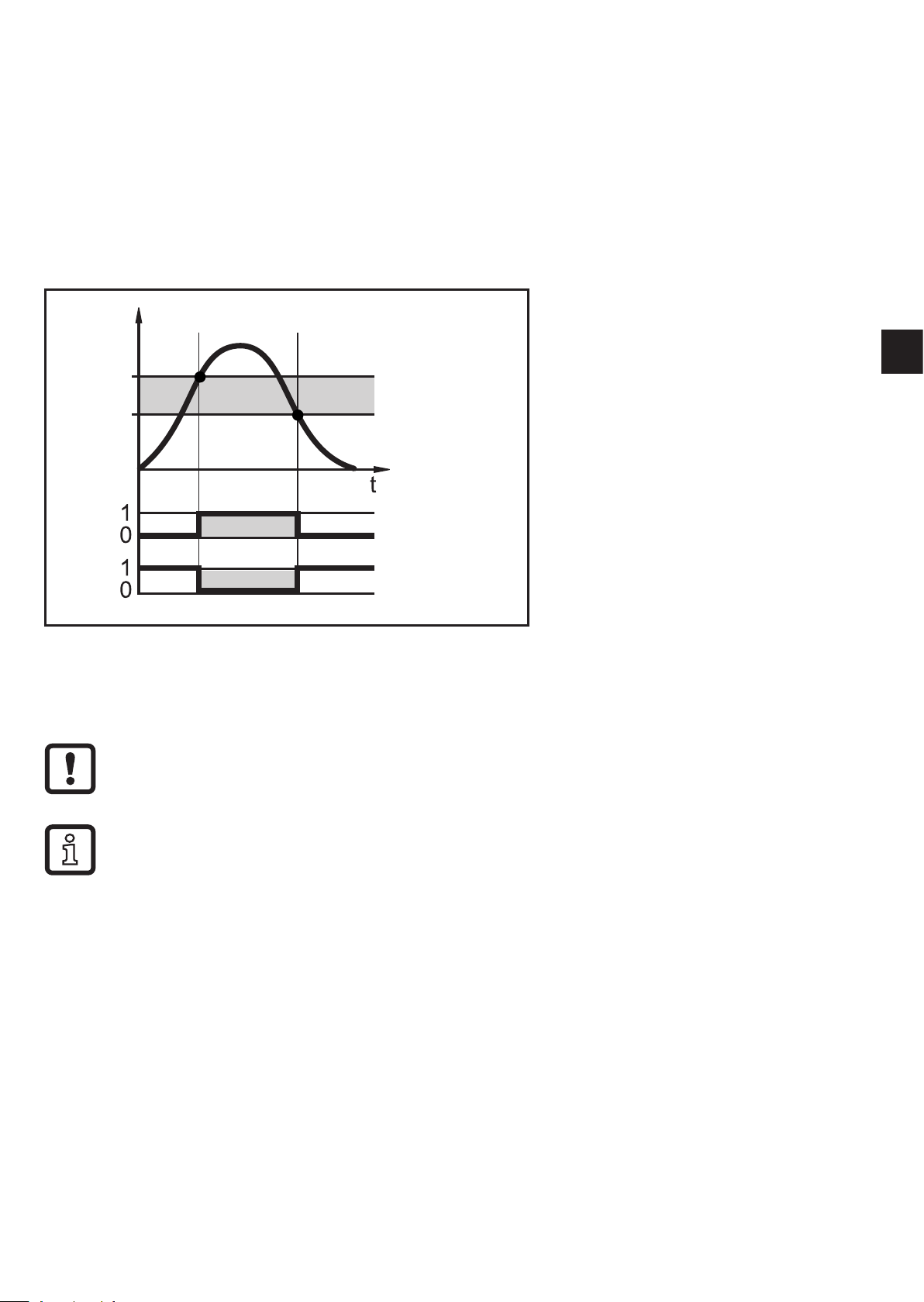
The unit switches the two complementary outputs OUT1 / OUT2:
With rising temperature OUT1 closes / OUT2 opens when the value SET is
reached.
With falling temperature OUT1 opens / OUT2 closes when the value RESET is
reached.
T
SET
HY
RESET
T = Temperature
OUT1 (Hno)
Hno = normally open
UK
OUT2 (Hnc)
HY = Hysteresis
4 Installation
Before mounting and removing the unit:
► Ensure that no medium can leak at the process connection.
Horizontal mounting recommended for high medium temperatures.
► Insert the unit in a process connection and tighten firmly. Recommended
Tightening torque:
- Process connection G ¼: 35 Nm
Hnc = normally closed
- Process connection ¼" NPT: 1.5 turns past hand tight
3
Page 4
5 Electrical connection
The unit must be connected by a qualified electrician.
The national and international regulations for the installation of electrical
equipment must be adhered to.
Voltage supply according to EN 50178, SELV, PELV.
► Disconnect power.
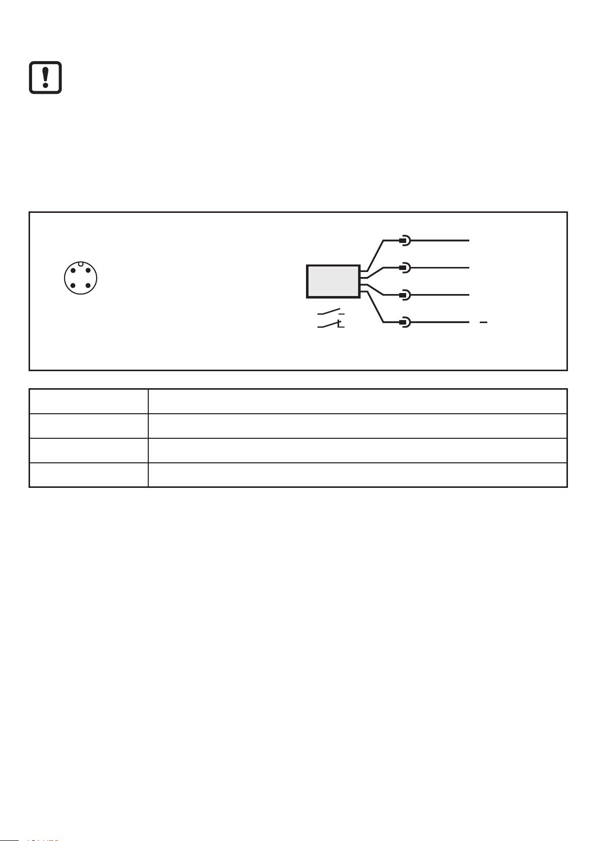
► Connect the unit as follows:
2 1
43
BK: black
BN: brown
BU: blue
WH: white
4:
2:
BN
1
WH
2
BK
4
BU
3
+
L
OUT2
OUT1
L
Colours to DIN EN 60947-5-2
Pin 1 L+
Pin 3 L-
Pin 4 (OUT1) Normally open (NO)
Pin 2 (OUT2) Normally closed (NC)
4
Page 5
6 Setting
R
et
S
eset
UK
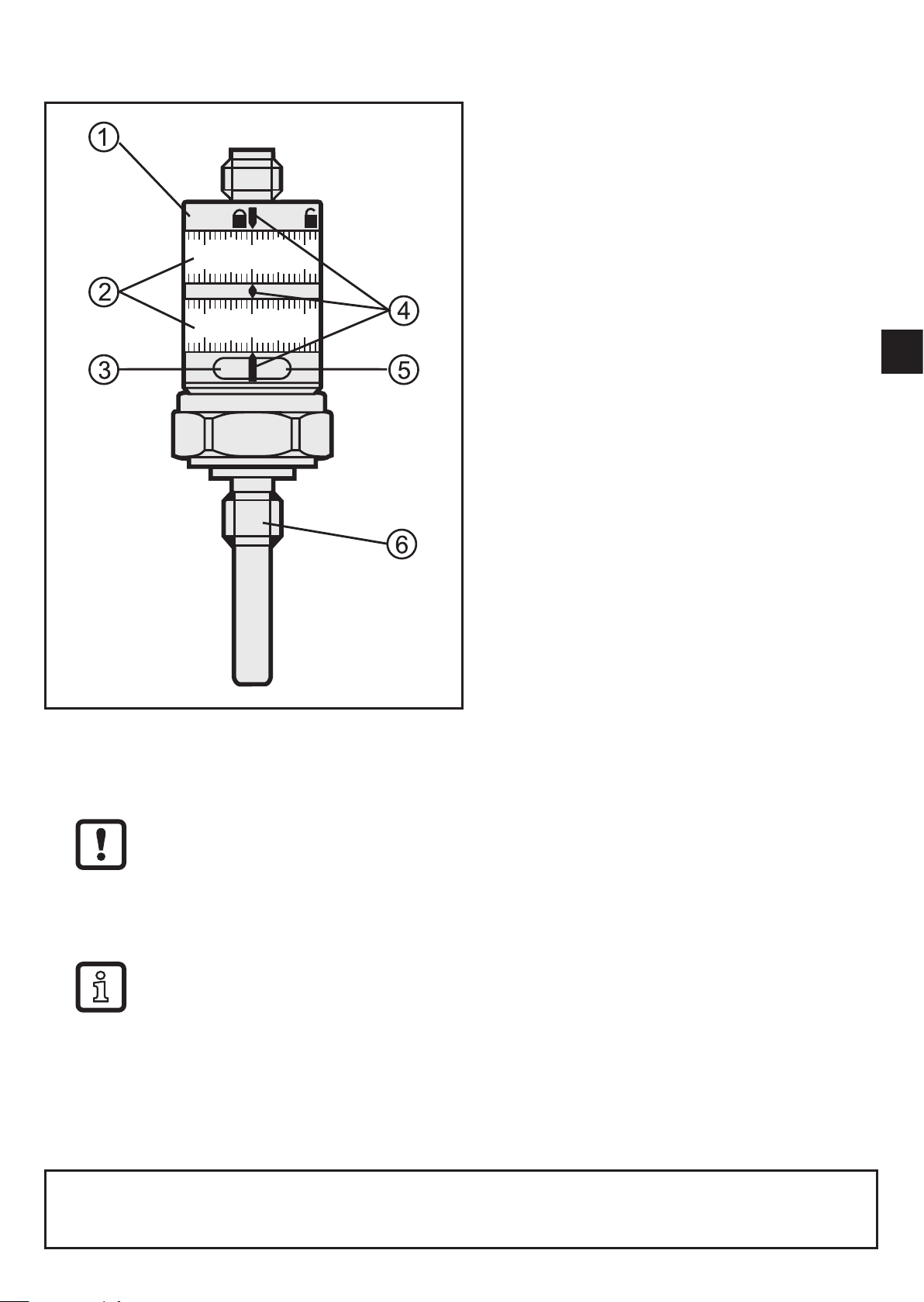
1: locking ring
2: setting rings
3: LED green: supply voltage
4: setting marks
5: LED yellow:
Temperature ≥ SET;
OUT1 closed / OUT2 open
6: process connection
► Turn the locking ring to the unlocked position.
► Turn both setting rings to the lowest setting.
This is important to ensure the setting accuracy.
► Rotate SET ring to desired temperature.
► Rotate RESET ring to desired temperature.
The RESET value must be lower than the SET value.
Minimum distance between SET and RESET = 3 K (= hysteresis).
► Turn the locking ring to the locked position.
Technical data, approvals, accessories and further information at
www.ifm.com.
5
 Loading...