

Page 1
Operating instructions
Optical distance sensor
OID20x
UK
80284285 / 00 04 / 2019
Page 2

Contents
1 Preliminary note ��������������������������������������������������������������������������������������������������� 3
1�1 Symbols used ������������������������������������������������������������������������������������������������3
1�2 Warning signs used ���������������������������������������������������������������������������������������3
2 Safety instructions �����������������������������������������������������������������������������������������������3
3 Functions and features ����������������������������������������������������������������������������������������5
3�1 Applications ���������������������������������������������������������������������������������������������������5
4 Installation������������������������������������������������������������������������������������������������������������5
4�1 Installation conditions ������������������������������������������������������������������������������������5
5 Electrical connection �������������������������������������������������������������������������������������������� 5
6 Setting / Operation ����������������������������������������������������������������������������������������������� 6
7 IO-Link �����������������������������������������������������������������������������������������������������������������7
7�1 General information ���������������������������������������������������������������������������������������7
7�2 Device-specific information ����������������������������������������������������������������������������7
7�3 Parameter setting tools ����������������������������������������������������������������������������������7
8 Maintenance, repair and disposal ������������������������������������������������������������������������ 7
2
Page 3

1 Preliminary note
1.1 Symbols used
► Instruction
> Reaction, result
[…] Designation of pushbuttons, buttons or indications
→ Cross-reference
Important note
Non-compliance can result in malfunctions or interference�
Information
Supplementary note�
1.2 Warning signs used
WARNING
Warning of serious personal injury�
Death or serious irreversible injuries may result�
UK
2 Safety instructions
• Please read this document prior to set-up of the unit� Ensure that the product is
suitable for your application without any restrictions�
• Improper or non-intended use may lead to malfunctions of the unit or to
unwanted effects in your application� That is why installation, electrical
connection, set-up, operation and maintenance of the unit must only be carried
out by qualified personnel authorised by the machine operator�
• In case of malfunction of the unit please contact the manufacturer� If the unit is
tampered with and/or modified, any liability and warranty is excluded�
• The unit conforms to the standard EN 61000-6-4� The unit may cause radio
interference in domestic areas� If interference occurs, the user must take
appropriate remedial actions�
3
Page 4
WARNING
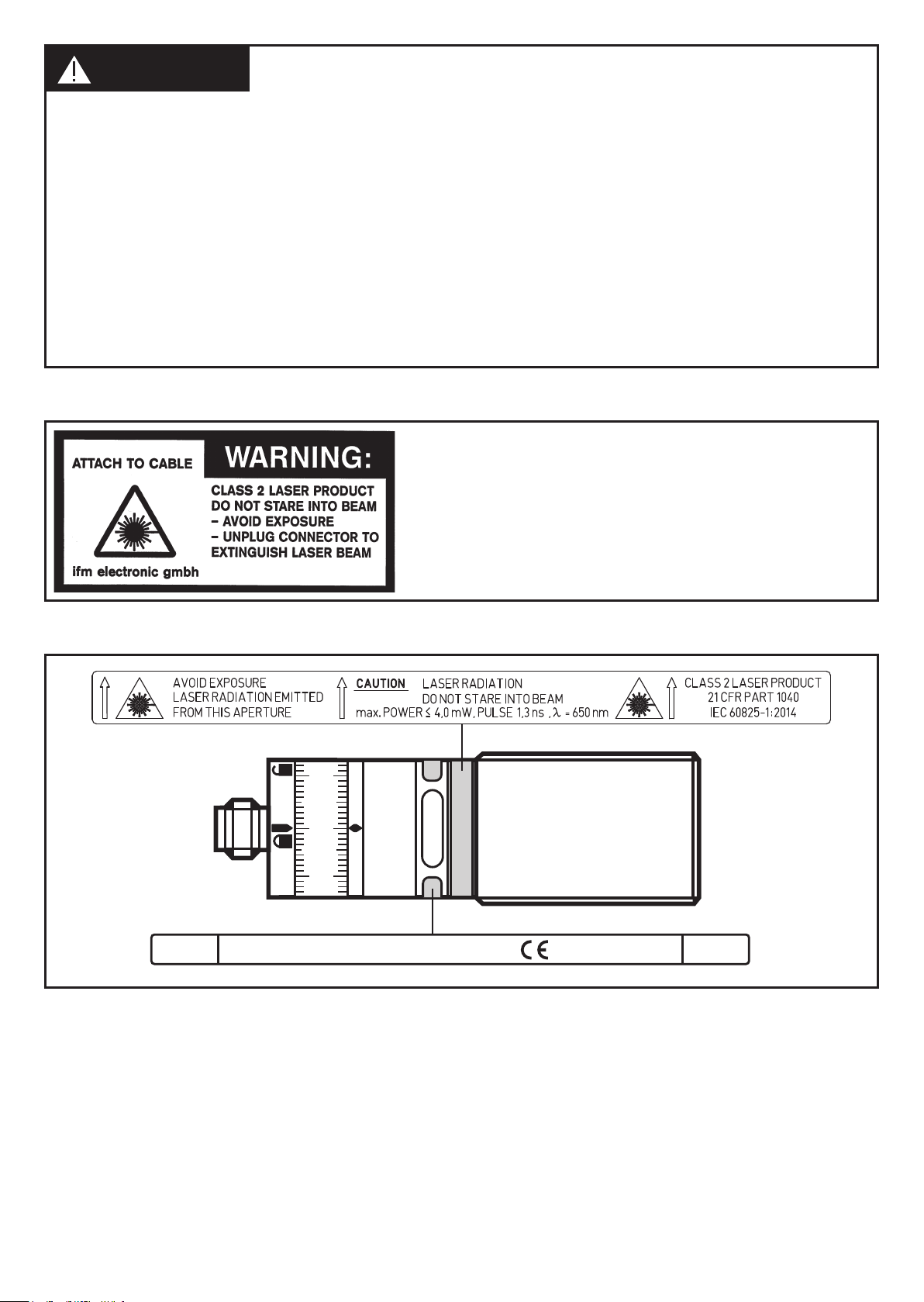
Visible laser light; laser protection class 2�
Use of controls or adjustments other than those specified herein may result in hazardous
radiation exposure� Damage to the retina is possible�
► Do not stare into the laser beam!
► Apply the enclosed labels (laser warning) in the immediate vicinity of the unit�
► Adhere to the caution and warning notes on the product label�
► Use the enclosed label for the power supply cable�
► EN/IEC 60825-1 : 2007 and EN/IEC 60825-1 : 2014 complies with 21 CFR 1040
except for deviations pursuant to Laser Notice No� 50, dated June 2007
Label for supply cable
Product label
D-45128 Essen
OID2xxPOWER
CLASS 2
LASER PRODUCT
www.ifm.com
TS AA 1301
OUT
4
Page 5
3 Functions and features
43
2
1
The unit is used as an optical distance sensor�
3.1 Applications
• The optical distance sensor measures distances between 0�03 and 2 m�
• It has a background suppression of up to 20 m�
• The switching outputs are complimentary�
The distance between the sensor and the background must be limited
to max� 20 m by the customer� Otherwise the measured value may be
UK
ambiguous. → 4.1 Installation conditions
4 Installation
4.1 Installation conditions
► Install the unit so that the object to be detected is within a measuring range of
0�03���2 m�
Any object between the set switch point and a distance of 20 m from the sensor is
suppressed�
Reflecting objects in the direct beam path of the sensor - also in the range
> 20 m – are to be avoided by the customer� Otherwise the measured
values may be ambiguous�
5 Electrical connection
The unit must be connected by a qualified electrician�
► The national and international regulations for the installation of electrical
equipment must be adhered to�
► Ensure voltage supply according to EN 50178, SELV, PELV�
► Disconnect power�
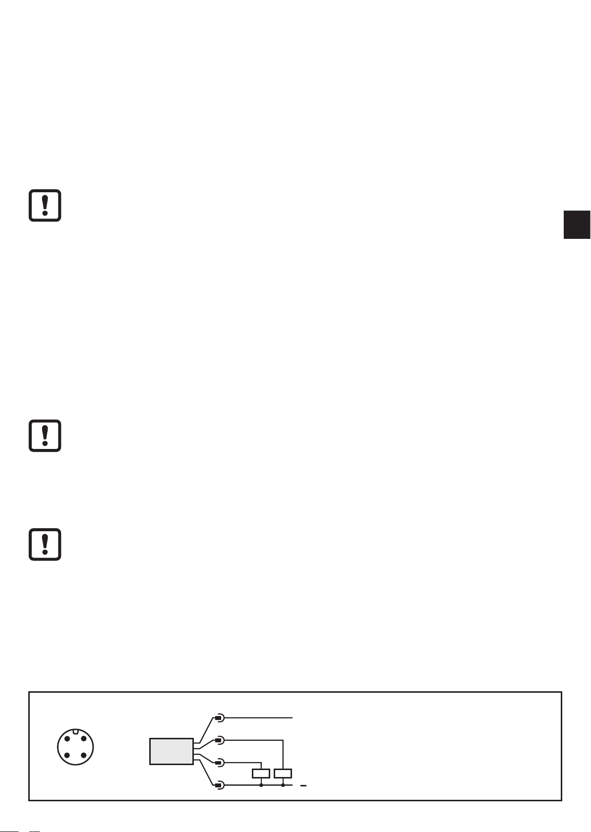
► Connect the unit as follows:
DC PNP
4: OUT1 = normally open / IO-Link
2: OUT2 = normally closed
5
Page 6
DC NPN
43
2
1
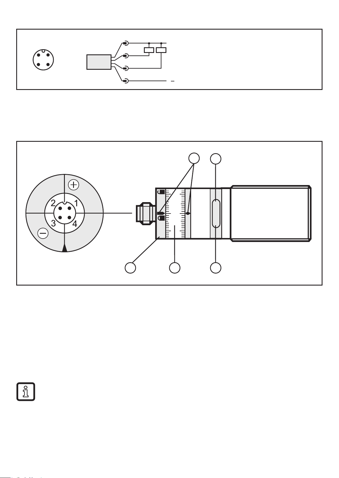
4: OUT1 = normally open / IO-Link
2: OUT2 = normally closed
Core colours of ifm sockets:
1 = BN (brown), 2 = WH (white), 3 = BU (blue), 4 = BK (black)
6 Setting / Operation
100 mA
PNP
OUT2
1
V
D
100 mA
OUT1
0
.
.
.
3
0
C
PNP
3
1
4
2
5
1: Setting marks
2: Yellow LED: Set1 value reached, output = ON
3: Locking ring
4: Setting ring (manually adjustable after unlocking)
5: Green LED: supply voltage O�K�
• To obtain the setting accuracy: Set the ring to the maximum value, then set the
requested value�
► After mounting, wiring and programming check whether the unit operates correctly�
Lifetime of a laser diode: 50,000 hours
6
Page 7

7 IO-Link
7.1 General information
This unit has an IO-Link communication interface which requires an IO-Linkcapable module (IO-Link master) for operation�
The IO-Link interface enables direct access to the sensor values and parameters
and provides the possibility to set the parameters of the unit during operation�
In addition communication is possible via a point-to-point connection with a USB
adapter cable�
UK
You will find more detailed information about IO-Link at www�ifm�com�
7.2 Device-specific information
You will find the IODDs necessary for the configuration of the IO-Link unit and
detailed information about sensor values, diagnostic information and parameters
in the overview table at www�ifm�com�
7.3 Parameter setting tools
You will find all necessary information about the required IO-Link hardware and
software at www�ifm�com�
8 Maintenance, repair and disposal
Faulty sensors must only be repaired by the manufacturer�
► Keep the front lens of the sensor free from soiling�
► After use dispose of the unit in an environmentally friendly way in accordance
with the applicable national regulations�
► Do not try to open the module enclosure� There are no user-serviceable
components inside�
Technical data and further information at www�ifm�com
7
 Loading...