

Page 1

Device Manual
RFID evaluation unit
DTE103
706429 / 00 12 / 2016
UK
Page 2

2
Contents
1 Preliminary note ....................................................................4
1.1 Symbols used..................................................................4
2 Safety instructions ..................................................................4
3 Functions and features...............................................................4
3.1 Configuration via Ethernet interface .................................................4
3.2 Functions for commissioning ......................................................4
4 Function .........................................................................5
4.1 Connection ....................................................................5
4.1.1 "AUX" voltage supply ........................................................6
4.1.2 Field bus connection EtherCAT In / Out ..........................................6
4.1.3 Process connections "IO-1 ... IO-4" .............................................6
4.2 Allowed network infrastructures ....................................................7
5 Installation.........................................................................7
6 Operating and display elements........................................................8
6.1 Reset to factory settings..........................................................8
6.2 Force firmware update ...........................................................8
6.3 LED indicators .................................................................8
6.3.1 LED AUX .................................................................8
6.3.2 LED EtherCAT IN / OUT......................................................8
6.3.3 LED RUN (operating state)....................................................9
6.3.4 LED ERR (error state) .......................................................9
6.3.5 LEDs IO1 ... IO4............................................................9
6.3.6 Special evaluation unit - LED indications ........................................10
7 Putting into operation ...............................................................10
8 Web server .......................................................................11
8.1 Verify and set the IP address of the PC .............................................11
8.2 Tab "Home"...................................................................13
8.3 Tab "Firmware" ................................................................14
8.4 Tab "IO-Port"..................................................................15
8.5 Tab "Monitor" .................................................................17
8.5.1 Tab "Monitor" - read/write head information ......................................18
8.5.2 Tab "Monitor" - Antenna firmware..............................................19
8.5.3 Tab "Monitor" -Tag monitoring ................................................21
8.5.4 Tab "Monitor" - Reading from the RFID tag ......................................21
8.5.5 Tab "Monitor" - Writing to the RFID tag .........................................22
8.6 Tab "System" .................................................................23
8.7 Tab "Info" ....................................................................24
8.8 Tab "Reset" ...................................................................25
9 Configuration .....................................................................26
9.1 Parameter setting of the Ethernet interface ..........................................26
9.2 Determining the MAC address ....................................................27
9.3 Connection concept of the EtherCAT interface........................................27
9.3.1 Socket connection EtherCAT In and Out ........................................27
9.4 EtherCAT device profile .........................................................27
10 PLC process data image ...........................................................28
10.1 Address model of the RFID evaluation unit with EtherCAT interface . . . . . . . . . . . . . . . . . . . . . .28
10.1.1 Process data input image...................................................28
10.1.2 Process data output image..................................................28
11 Parameter setting .................................................................29
11.1 Device parameters ............................................................29
11.1.1 Failsafe mode ............................................................29
11.2 Module setting ...............................................................29
11.3 Module parameters............................................................30
11.3.1 Setup “IO-channel mode” ...................................................30
11.3.2 Setup "Data hold time" .....................................................30
Page 3

3
UK
11.3.3 Setup “Transponder data block length”.........................................31
11.3.4 Setup “Overload and Overcurrent detection” ....................................31
11.3.5 Setup “Read UID edge controlled” ............................................31
12 Module description . . . . . . . . . . . . . . . . . . . . . . . . . . . . . . . . . . . . . . . . . . . . . . . . . . . . . . . . . . . . . . . .32
12.1 Module “Inactive” .............................................................33
12.2 Module “Input” ...............................................................35
12.3 Module “Output” ..............................................................37
12.4 Module “RWH_RW”, general description ...........................................39
12.5 Module “RWH_RW”, Read UID of the RFID tag synchronously..........................41
12.6 Module “RWH_RW”, Read UID of the RFID tag asynchronously.........................43
12.7 Module “RWH_RW”, Read User data of the RFID tag synchronously .....................45
12.8 Module “RWH_RW”, Read User data of the RFID tag asynchronously ....................47
12.9 Module “RWH_RW”, Write User data of the RFID tag .................................49
12.10 Module “RWH_RW”, Write verified User data of the RFID tag..........................51
12.11 Restart of the evaluation unit ...................................................53
13 Data frame examples . . . . . . . . . . . . . . . . . . . . . . . . . . . . . . . . . . . . . . . . . . . . . . . . . . . . . . . . . . . . . .55
13.1 Read UID on request (synchronous mode) .........................................55
13.1.1 Command sequence view ..................................................55
13.1.2 Payload traffic view........................................................56
13.2 Receive UID automatically (asynchronous mode) ....................................57
13.2.1 Command sequence view ..................................................57
13.2.2 Payload traffic view........................................................58
13.3 Access to the User data of the RFID tag ...........................................59
13.4 Read User data of the RFID tag on request (synchronous mode) ........................60
13.4.1 Command sequence view ..................................................60
13.4.2 Payload traffic view........................................................61
13.5 Write User data to the RFID tag (synchronous mode) .................................62
13.5.1 Command sequence view ..................................................62
13.5.2 Payload traffic view........................................................63
13.6 Write verified to user memory to the RFID tag (synchronous mode) ......................64
13.6.1 Command sequence view ..................................................64
13.6.2 Payload traffic view........................................................65
13.7 Read User data of the RFID tag automatically (asynchronous mode) .....................66
13.7.1 Command sequence view ..................................................66
13.7.2 Payload traffic view........................................................67
13.8 Read diagnostics information ....................................................68
13.8.1 Command sequence view, read diagnostics in mode “Read UID” ....................68
13.8.2 Payload traffic view, read diagnostics in mode “Read UID” .........................69
13.8.3 Command sequence view, read diagnostics in mode “Read/write User data of the RFID tag” .70
13.8.4 Payload traffic view, read diagnostics in mode “Read/write User data of the RFID tag” ...71
14 Error codes of the evaluation unit.....................................................72
14.1 Error group RFID tag (F1FE) ....................................................72
14.2 Error group evaluation unit (F4FE)................................................72
14.3 Error group Communication User – evaluation unit (F5FE ) ............................73
15 List of abbreviations ...............................................................74
Licences and trademarks
Microsoft® and Internet Explorer® are registered trademarks of Microsoft Corporation.
EtherCAT® and TwinCAT® are registered trademarks and patented technologies, licensed by Beckhoff
Automation GmbH, Germany.
All trademarks and company names are subject to the copyright of the respective companies.
Page 4

4
1 Preliminary note
1.1 Symbols used
► Instruction
> Reaction, result
[…] Designation of pushbuttons, buttons or indications
→ Cross-reference
Important note
Non-compliance can result in malfunction or interference
Information
Supplementary note
2 Safety instructions
Please read the operating instructions prior to set-up of the device. Ensure that the device is suitable for
your application without any restrictions
If the operating instructions or the technical data are not adhered to, personal injury and/or damage to
property can occur
3 Functions and features
The RFID evaluation unit integrates an Ethernet interface and 4 channels for the connection of field
devices. Each channel can be used either for the connection of a read/write head or as a input/output to
IEC 61131.
The device
● controls the data exchange to the read/write heads or the sensor/actuator level.
● communicates with the higher control level via Ethernet.
● allows device configuration via a web server.
Application examples:
● Material flow control in production lines
● Warehouse management by the automatic detection of stored products
● Tank management, order picking or product tracking
3.1 Configuration via Ethernet interface
● 10 Mbps and 100 Mbps
● TCP / IP - Transport Control Protocol / Internet Protocol
● IT functionality: HTTP server
● M12, twisted pair
3.2 Functions for commissioning
Via the integrated Webserver it is possible to
● read the UID of the RFID tag
● read the user data area of the RFID tag
● write to the user data area of the RFID tag
● read the input of the IO channels
Page 5
5
UK
● write to the output of the IO channels
● read the device information of the evaluation unit
● read the device information of the connected read/write heads
● update the firmware of the read/write heads
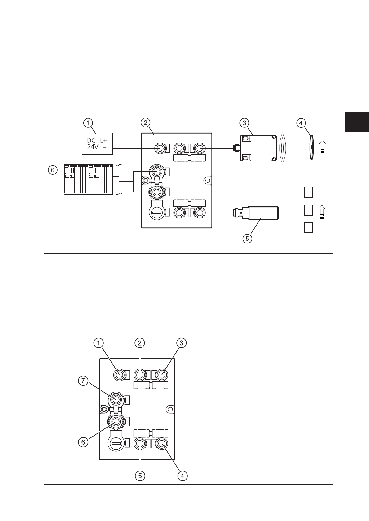
4 Function
1: Voltage supply
2: DTE103 RFID evaluation unit
3: read/write head type ANT51x / ANT41x
4: RFID tag
5: Sensor
6: Ethernet host
The evaluation unit processes data from up to 4 RFID read/write heads (type ANT41x, ANT42x, ANT43x,
ANT51x) or IEC 61131 inputs / outputs. The mode of operation for each channel can be set individually
via the EtherCAT controller.
For further information about port configuration, see (→ 9 Configuration)
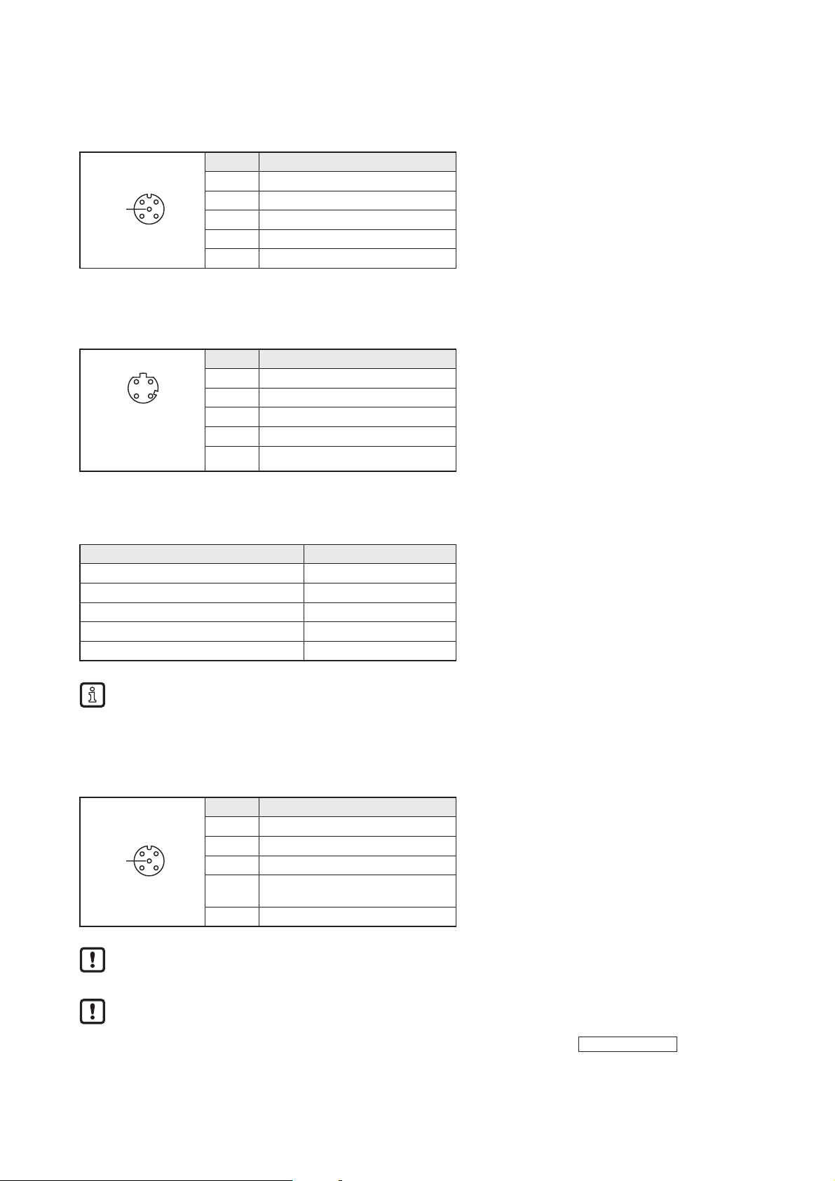
4.1 Connection
1: AUX voltage supply
2: Process connection IO-1
3: Process connection IO-2
4: Process connection IO-4
5: Process connection IO-3
6: Ethernet Port 1
7: Ethernet Port 2
Page 6
6
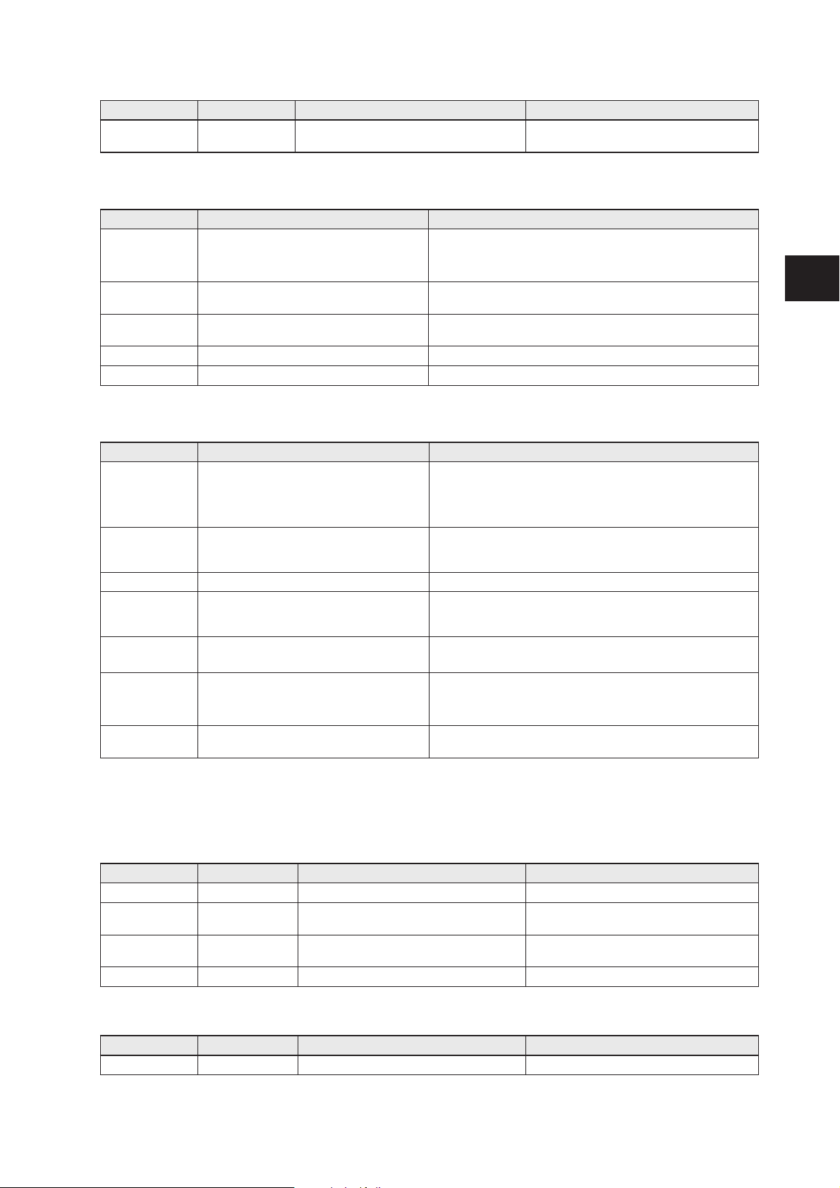
4.1.1 "AUX" voltage supply
► Connect the evaluation unit to the voltage supply using an M12 connection cable.
3
12
4
5
Pin Connection
1 24 V DC
2 not used
3 0 V
4 not used
5 not used
4.1.2 Field bus connection EtherCAT In / Out
► Connect the evaluation unit to an EtherCAT controller using a suitable M12 Ethernet connection cable.
12
34
Pin Connection
1 TD+
2 RD+
3 TD-
Note: screened
connection cable
required
4 RD-
Factory setting of the Ethernet parameters
The following values are preset on delivery of the evaluation unit:
Parameters Factory setting
IP address 192.168.0.79
Gateway address 192.168.0.100
Subnet mask 255.255.255.0
Auto-negotiation on
DHCP off
These values are only valid if the evaluation unit start up with the “Emergency System”. By default
the Ethernet parameters are set by the EtherCAT controller.
4.1.3 Process connections "IO-1 ... IO-4"
Each process connection can be used as input/output to IEC 61131 or for connection of an RFID read/
write head type ANT51x/ANT41x.
3
12
4
5
Pin Connection
1 L+
2 switching input (I/Q)
3 L-
4
switching output (C/Qo) or
input (C/Qi)
5 not used
The evaluation unit has to be disconnected from the power supply before field units are connected.
Please note that the total current consumption of the evaluation unit must not exceed the value of
3 A.
You can find information about the matching read/write heads on our website at:
www.ifm.com
Page 7

7
UK
4.2 Allowed network infrastructures
Linear structure:
D D D D D
The linear structure is the default structure for EtherCAT network.
Star structure:
Switch
D
D D
Switch
D
D D
Switch
D
D D
The star structure is only possible with EtherCAT switches.
D: Device
5 Installation
You can find information about installation and electrical connection in the operating instructions for the
evaluation unit at:
www.ifm.com
Page 8

8
6 Operating and display elements
6.1 Reset to factory settings
The Ethernet parameters can be reset to the factory settings. Take the following steps:
► Remove all cable connections from the evaluation unit.
► Insert an electrically conductive bridge between pin 1 and pin 3 on the process connection IO-3.
► Connect the evaluation unit with the voltage supply and wait until the yellow LED indication on AUX
and IO-3 flashes at approx. 8 Hz.
► Remove the conductive bridge from process connection IO-3.
► Disconnect the evaluation unit from the voltage supply and connect it again.
> The settings are reset.
6.2 Force firmware update
The firmware of the Evaluation unit can be updated directly from a PC without using an EtherCAT
controller.
Execute the following steps:
► Remove all cable connections from the evaluation unit.
► Insert an electrically conductive bridge between pin 1 and 3 on the process connection IO-4.
► Connect the evaluation unit with the voltage supply and wait until the yellow LED indication on AUX
and IO-4 flash at approx. 8 Hz.
► Connect the evaluation unit at EtherCAT port “In” with a personal computer.
► Open a web browser and enter the address “http://192.168.0.79”.
► Start firmware update and wait until the firmware is written to the evaluation unit.
► Remove all cable connections from the evaluation unit.
> The firmware update is finished.
Furthermore it is possible to update the firmware over the EtherCAT controller by using the integrated
Web server of the evaluation unit or by using the FoE function of the EtherCAT protocol.
Do not interrupt power or disconnect cables from the system while the firmware update is in
progress.
6.3 LED indicators
The evaluation unit indicates the current status of the interface via the status LEDs.
6.3.1 LED AUX
LED green LED yellow Status Note
off off no voltage supply U
AUX
< 5 V
on flashes at 2 Hz voltage supply too low 5 V ≤ U
AUX
≤ 18 V
On flashes at 8 Hz Firmware update is running Do not switch off power supply
on off voltage supply OK 18 V ≤ U
AUX
≤ 36 V
6.3.2 LED EtherCAT IN / OUT
LED green LED yellow Status Note
Off Off
No connection to another Ethernet
counterpart
Link status "no link"“
On Off
Connection to Ethernet counterpart exits,
no data exchange
Link status "link", "no traffic"
Page 9
9
UK
LED green LED yellow Status Note
On
Flashes
sporadically
Connection to Ethernet counterpart exists,
data exchange running
Link status "link", "traffic"
6.3.3 LED RUN (operating state)
LED green Status Note
Off
Power off
or
INITIALISATION of the evaluation unit
Check the voltage supply.
Blinking
PRE OPERATIONAL state of the
evaluation unit
If this state is not reached, check settings of the device in the
PLC
Single Flash
SAFE OPERATIONAL state of the
evaluation unit
If this state is not reached, check the configuration string of the
device in the PLC
On OPERATIONAL state of the evaluation unit -
Flickering Firmware download in progress -
6.3.4 LED ERR (error state)
LED red Status Note
Off
Power off
or
no error
Check the voltage supply
or
The EtherCAT communication of the evaluation unit is in
working condition
Flickering
Booting error detected. INIT state reached,
but error indicator bit is set to 1 in AL status
register
Restart evaluation unit
Blinking General Configuration Error Check the configuration string of the evaluation unit in the PLC
Single Flash
Slave evaluation unit application has
changed the EtherCAT state autonomously,
due to local error
- overload at IO-channel 1..4
- short circuit at IO-channel 1..4
Double Flash
Process data watchdog timeout/
EtherCAT watchdog timeout
Sync Manager watchdog timeout
Triple Flash
Slave application error, e.g. vendor
specific AL status code returned
- under voltage at AUX
- temperature failure of the evaluation unit
- internal fault
On
Critical communication or application
controller error
Application controller is not responding anymore (PDI watchdog
timeout)
6.3.5 LEDs IO1 ... IO4
The LED indications of the process connections depend on the set mode of the IO channel.
Use as input to IEC 61131
LED green LED yellow Status Note
Off Off Interface deactivated Interface via Ethernet host not configured
On Off
Interface activated, input C/Qi on L level
(0 V)
-
On On
Interface activated, input C/Qi on H level
(24 V)
-
Flashes at 8 Hz Flashes at 8 Hz Overload or short circuit -
Use as output to IEC 61131
LED green LED yellow Status Note
Off Off Interface deactivated Interface via Ethernet host not configured
Page 10

10
LED green LED yellow Status Note
On Off
Interface activated, output C/Qo L-active
(0 V)
-
On On
Interface activated, output C/Qo H-active
(24 V)
-
Flashes at 8 Hz Flashes at 8 Hz Overload or short circuit -
Use with RFID read/write heads
LED green LED yellow Status Note
Off Off Interface deactivated Interface via Ethernet host not configured
Flashes at 2 Hz Off Interface activated, antenna field off -
On Off Interface activated, RFID tag not in the field -
On On Interface activated, RFID tag in the field -
Flashes at 8 Hz Flashes at 8 Hz
Overload, short-circuit or communication
error
-
6.3.6 Special evaluation unit - LED indications
LED Status Note
Green AUX LED on
Yellow AUX LED
flashes at 8 Hz
Yellow IO1...IO4 LEDs
flash at 8 Hz
Evaluation unit is in the service mode
"emergency system started".
A firmware update is necessary and can be
executed via the web server.
Green AUX LED on
Yellow AUX LED
flashes at 8 Hz
Green IO1...IO4 LEDs
flash at 8 Hz
Yellow IO1...IO4 LEDs
flash at 8 Hz
Major error, evaluation unit has to be
returned.
Hardware fault or permanent data in the
evaluation unit are corrupt.
Green AUX LED on
Yellow AUX LED
flashes at 8 Hz
Yellow IO3 LED
flashes at 8 Hz
Reset to factory settings -
7 Putting into operation
► Connect the evaluation unit according to the operating instructions.
> After connecting the operating voltage, the evaluation unit is ready for use.
The green power supply LEDs of the read/write heads will light up after enabling the corresponding
module in the module configuration.
Page 11

11
UK
8 Web server
The evaluation unit is equipped with an integrated web server that allows to
● read the UID of the RFID tag
● read from the User data area of the RFID tag
● write to the User data area of the RFID tag
● update the firmware of the evaluation unit
● update the firmware of the read/write heads
The settings are made via a web browser, e.g. Microsoft Internet Explorer® as from V7.0
To access the Web server following preconditions need to be fulfilled
● EtherCAT master with integrated EtherCAT switch or EtherCAT switch ( e.g. Beckhoff CU1128, /
EK1122 )
● PC connected to the EtherCAT master or EtherCAT switch
● evaluation unit connected to EtherCAT master
● EoE protocol of the evaluation unit activated. The IP address setting of the evaluation unit must be in
the network address range of the PC.
► Open the web browser on the PC and enter the IP address which is set in the EoE settings of the
evaluation unit.
The evaluation unit must be at least in EtherCAT slave state “Preoperational”.
The actualization time of the Webpages depend on the EtherCAT bus cycle time and the data
traffic of the EtherCAT network. The actualization time can vary between 2…30 seconds.
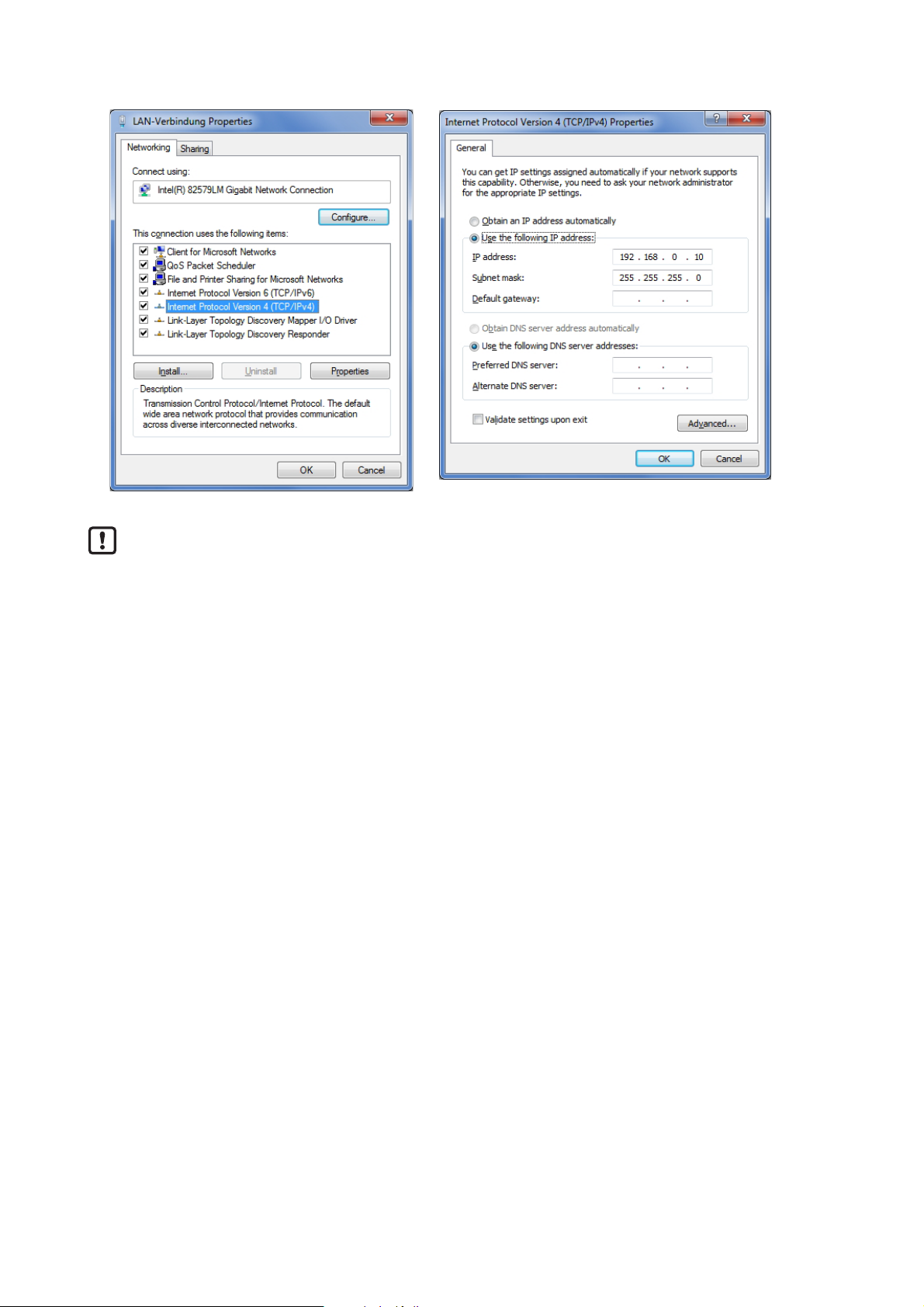
8.1 Verify and set the IP address of the PC
► Activate menu "Internet Protocol Version 4 (TCP/IPv4) Properties".
The Windows menu "Internet protocol (TCP/IP) Properties" is accessible for example via:
Start → Control Panel→ Network and Sharing Center → Change adapter settings → Local Area
Connection → Properties.
► Select the menu item "Use the following IP address".
► Verify and set the IP address, if necessary (here e.g. 192.168.0.10).
► Enter the subnet mask (255.255.255.0).
► Leave default gateway blank.
► Confirm the settings with [OK].
Page 12
12
Changes in the network settings of the PC require extended user rights.
Contact your system administrator.
Page 13

13
UK
8.2 Tab "Home"
This is the main menu from where all functions of the evaluation unit can be accessed. The user can
select the language of the evaluation unit web interface.
Page 14

14
8.3 Tab "Firmware"
This menu allows to update the firmware of the evaluation unit.
► Open the “Firmware” tab on the browser interface.
► Choose firmware file DTE103.nxf and commit via button [transfer]
Do not interrupt power or disconnect cables from the system while the firmware update is in
progress.
Page 15

15
UK
8.4 Tab "IO-Port"
This menu allows to configure the IO-Ports of the evaluation unit.
Each IO-channel can be configured to mode „Inactive“, „Input“, „Output“ and „RWH“.
Mode Function
Inactive No function, inactive
Input IEC 61131 input
Output IEC 61131 output
RWH RFID read/write head (Type ANT4xx or ANT5xx)
“Data hold time” define how long the RFID data are kept stable. This is helpful if the time interval, in which
the RFID tag data are available, is shorter than the host can read these from the RFID unit.
“Number of blocks” define the number of blocks available on the RFID tag.
“Block size” define the number of bytes per block available on the RFID tag.
If the value "Block size" does not match the physically value of the RFID tag, the read and write
commands will fail.
“UID edge controlled" allow the reading of the UID of the RFID tag once by setting bit "RD" from 0 to 1 in
the process data output image of the controller. This mode is suitable if the user knows when the RFID
tag is present in front of the read/write head. The read UID is kept in the data bytes 2…18 stable while bit
RD is set to 1.
► Set “Overload detection” to “off” if the load on terminal “L+” is above 0,5 A.
The current is limited to 0,7 A by hardware.
Page 16

16
► Set “Overcurrent detection” to “off” if load on terminal “C/Qo” is above 0,5 A.
The current is limited to 0,6 A by hardware.
► Set "High Current" to “on” if the current on ports IO-3 and/or IO-4, terminal “C/Qo”, shall be possible to
1 A.
The maximum power input shall not exceed 3,0 A, otherwise the evaluation unit can be
damaged.
Button Function Remark
Activate and save The settings are activated
and stored non-volatile
After next power-on the stored settings are activated. If
the host connect to the evaluation unit and write a new
IO-Port configuration the stored values are overwritten
Cancel Discard changes -
Page 17
17
UK
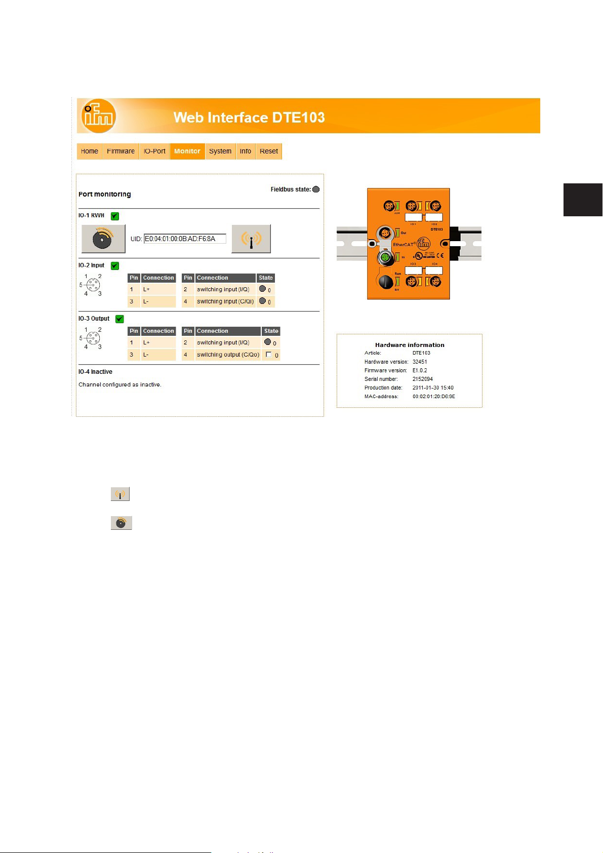
8.5 Tab "Monitor"
This menu shows the data of each port which is detected by the evaluation unit.
In this example the IO-1 port is configured as RFID read/write head, IO-2 port as input, IO-3 port as
output and IO-4 port as inactive.
► Click to switch to submenu "read/write head information" (→ 8.5.1 Tab "Monitor" - read/write head
information).
► Click to switch to submenu "Tag monitoring - read and write" (→ 8.5.3 Tab "Monitor" -Tag
monitoring).
Page 18

18
8.5.1 Tab "Monitor" - read/write head information
This menu shows the following information about the selected read/write head:
● Article number
● Device type
● Hardware version
● Firmware version
● ID link software
● Production date
Button Function Remark
Update Go to menu “Antenna firmware” -
Back Return to the main menu -
Page 19
19
UK
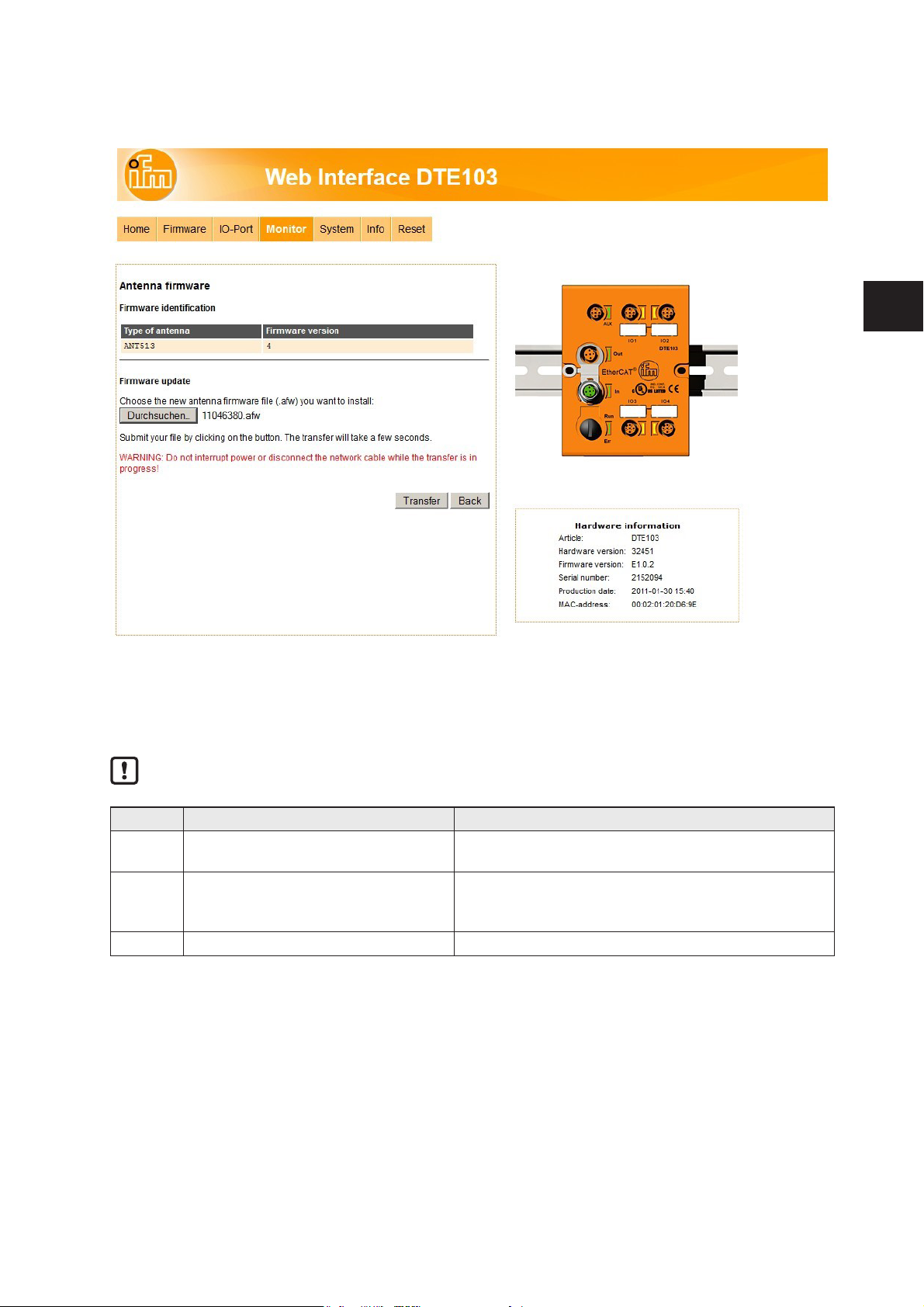
8.5.2 Tab "Monitor" - Antenna rmware
This menu allows to update the firmware of the read/write head connected at the selected port.
► Open the “Firmware” tab on the browser interface.
► Choose firmware file "xxx.afw" and submit via button [Transfer].
Do not interrupt power or disconnect cables from the system while the firmware transfer is in
progress.
Button Function Remark
Search Open new dialog window to browse
to the read/write head firmware file
-
Transfer Send antenna firmware to connected
read/write head
If the update process is finished the evaluation unit
reboots the read/write head automatically. A restart of
the evaluation unit is not necessary.
Back Return to the main menu. -
Page 20

20
If the firmware update fail or the read/write head is not detected by the evaluation unit at the selected IOport, the read/write head is accessible via web browser and the following URL:
http://<IP-ADDRESS>/rwhupdate?ioport=<IO-CHANNEL>1&anttype=<ANTENNA_TYPE> &fwVersion=
<NUMBER>&setLng=<LANGUAGE>
Parameter name Description Remark
IP-ADDRESS IP address of the evaluation unit [XXX.XXX.XXX.XXX] IPV4 address
IO-CHANNEL IO-Channel number [1…4] -
ANTENNA_TYPE Article number of the read/write head [e.g. ANT512] 6 digit article number
NUMBER Firmware number [01] 2 digit number. Shall be
set to “01”
LANGUAGE Language of the website [de, en, es, fr, it, ko, pt, ru, zh] -
Example of URL:
http://192.168.0.79/diagrwh?ioport=1&anttype=ANT513&fwVersion=01&setLng=en
After finishing the firmware update of the read/write head, enter the URL of the evaluation unit to
return to the main menu (→ 8 Web server).
Page 21
21
UK
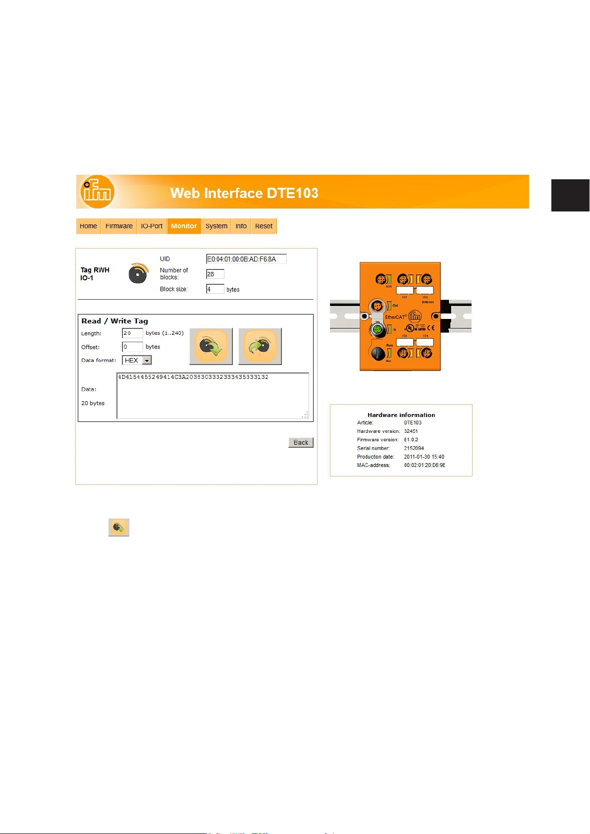
8.5.3 Tab "Monitor" -Tag monitoring
This menu allows to:
● read the UID from the RFID tag
● read from or write to the user data area of the RFID tag
8.5.4 Tab "Monitor" - Reading from the RFID tag
The UID data is displayed in real time with an update interval of approximately 0,5 seconds.
► Click to read from the User data area of the RFID tag.
The data length can be set from 1...240 bytes. The address offset can be set from 0 bytes up to the last
accessible address of the RFID tag.
► Click [Back] to return to the main menu.
With the selection field „Data format“ the received RFID tag data can be displayed in two formats:
● „HEX“: Data displayed in hexadecimal format.
Example: „4D4154455249414C3A2038303332333435333132“
● „ASCII“: Data displayed as ASCII character string.
Example: „MATERIAL: 8032345312“
Page 22
22
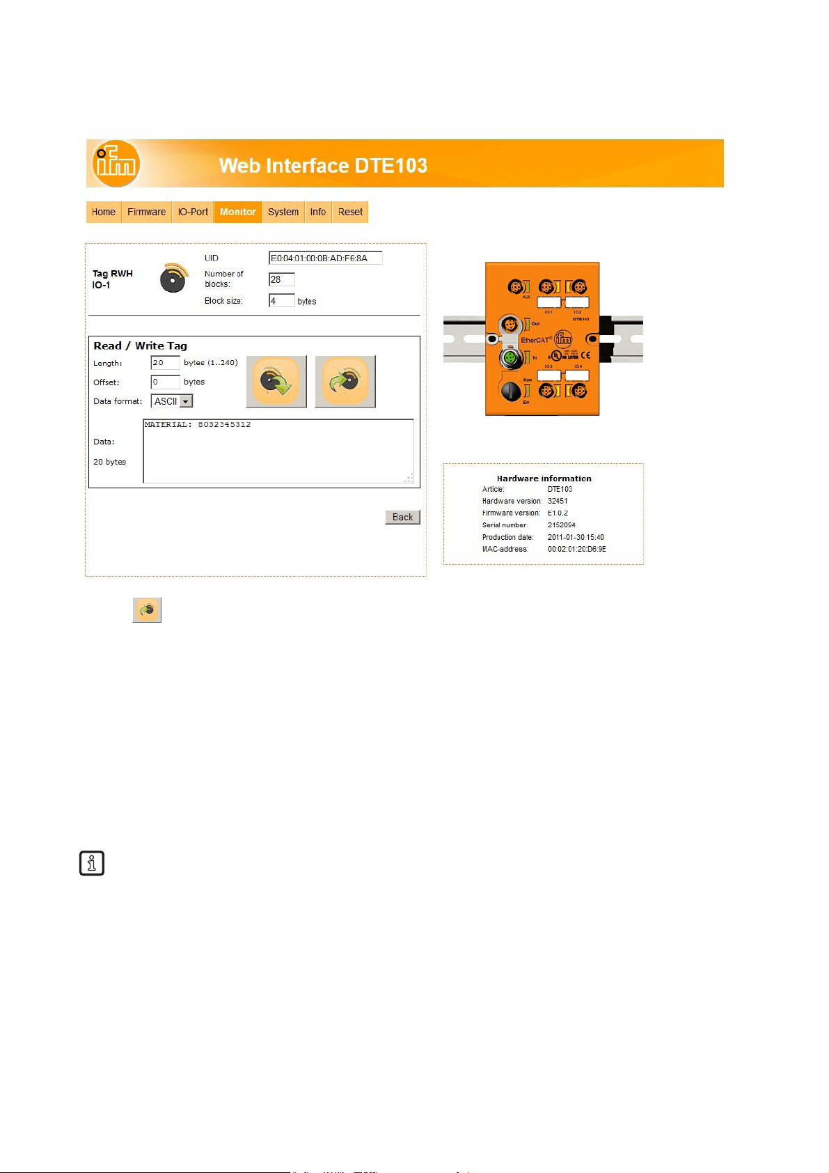
8.5.5 Tab "Monitor" - Writing to the RFID tag
► Click to write to the User data area of the RFID tag.
The data length to be written can be set from 1...240 bytes. The address offset can be set from 0 bytes up
to the last accessible address of the RFID tag. The data length to be written must correspond to the set
number of bytes.
► Click [Back] to return to the main menu.
With the selection field „Data format“ the RFID tag data can be input in two formats:
● „HEX“ : Data input in hexadecimal format.
Example: „4D4154455249414C3A2038303332333435333132“
● „ASCII“: Data input as ASCII character string.
Example: „MATERIAL: 8032345312“
The parameter “Length” is automatically calculated.
Page 23
23
UK
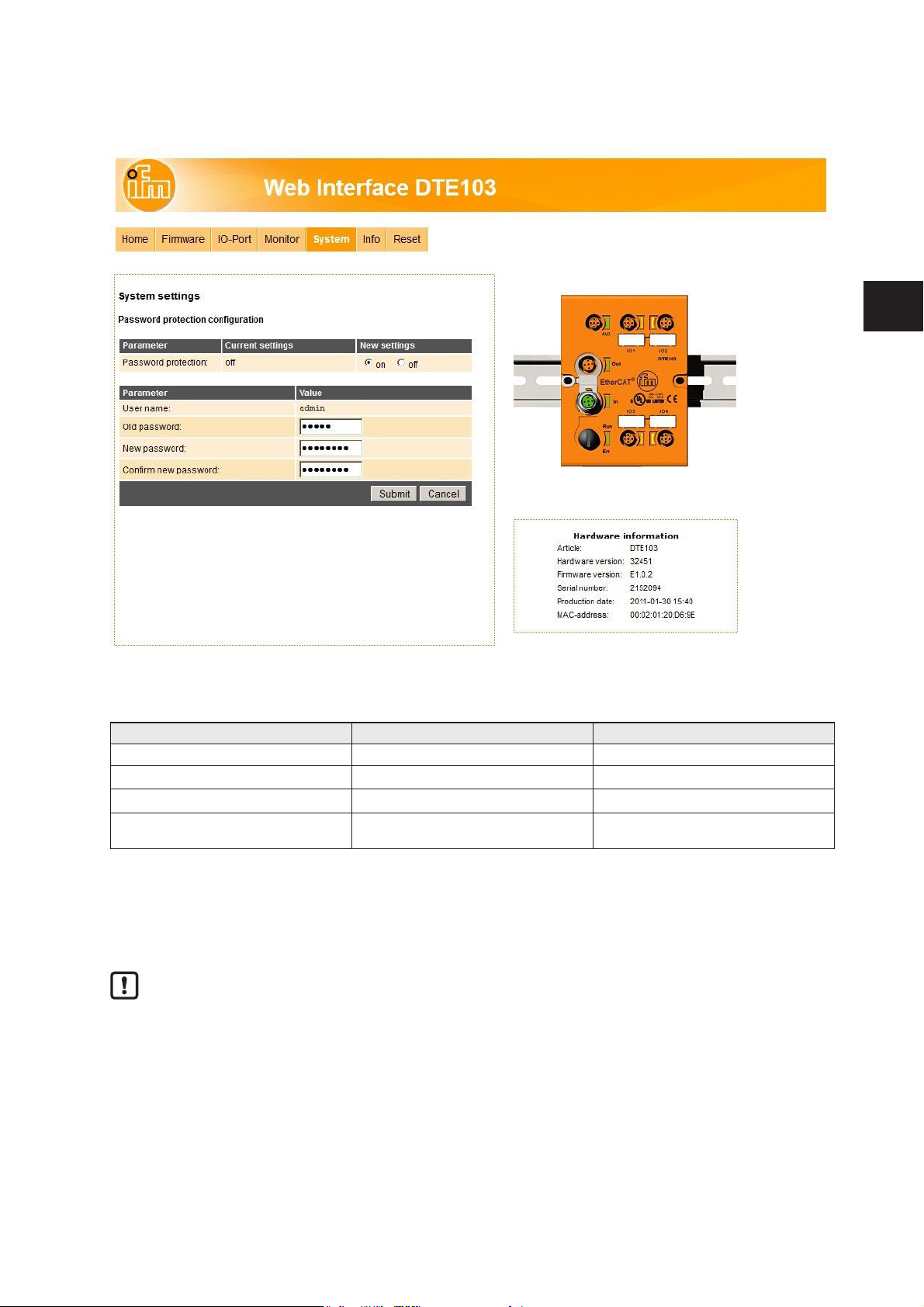
8.6 Tab "System"
This menu allows to define a password to protect the evaluation unit against unauthorised access.
To enable the password protection the button "New settings" has to be set to "on".
Parameter Setting Note
Username admin User name could not be changed
Old password XXXXXX Default password is "admin"
New password XXXXXX Up to 10 characters are allowed
Confirm new password XXXXXX Must correspond to the parameter setting
"New password"
► Click [Submit] to save the password
► Click [Cancel] to delete all parameter settings
If the password is lost the default password "admin" can be retrieved by a reset to factory settings
(→ 6.1 Reset to factory settings).
Page 24
24
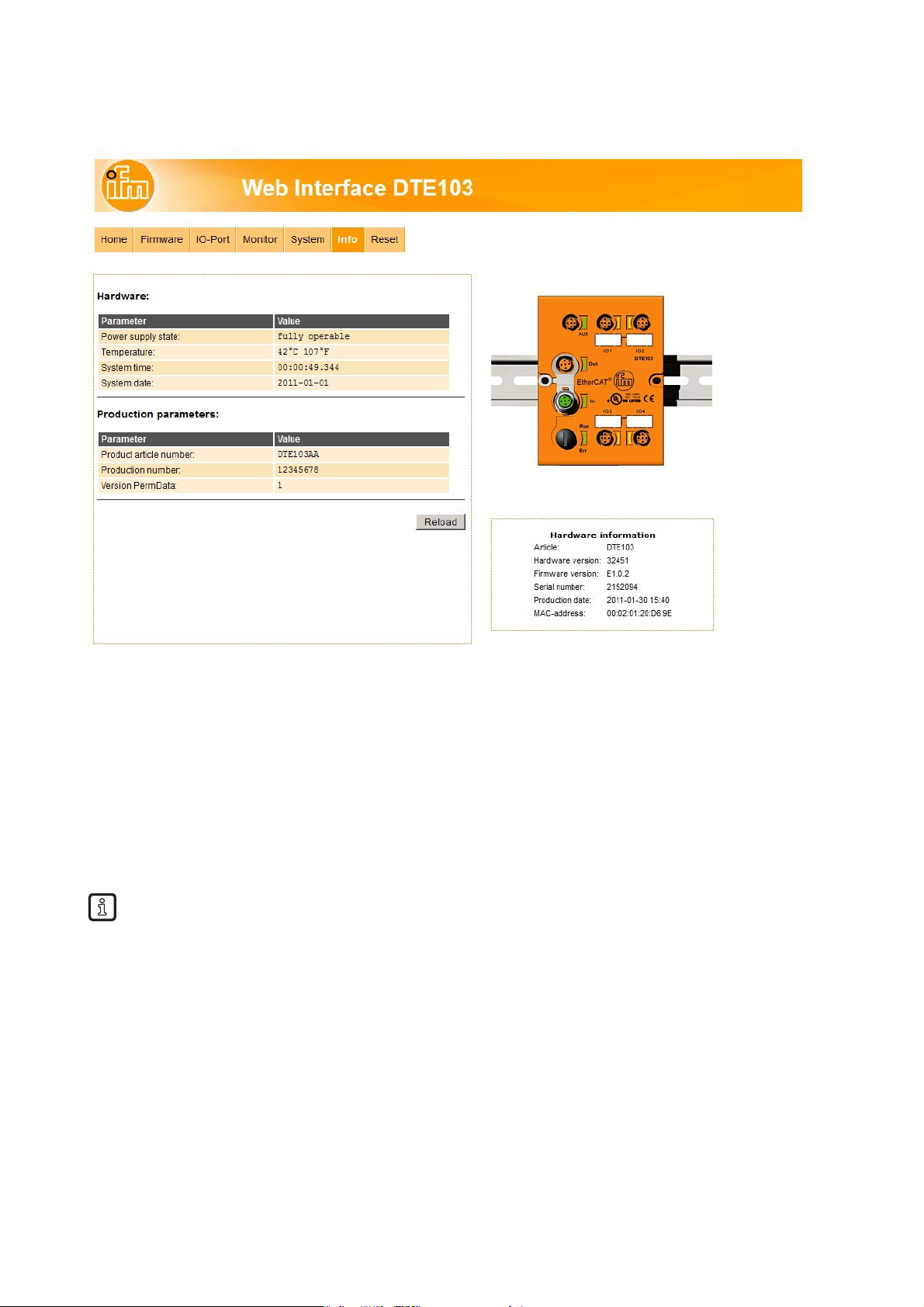
8.7 Tab "Info"
This menu shows the following information about the evaluation unit:
● Power supply state
● Temperature
● System time
● System date
● Product article number
● Production number
● Version PermData
For a proper operation of the evalution unit the "Power Supply State" should show as
"fully operable".
Page 25
25
UK
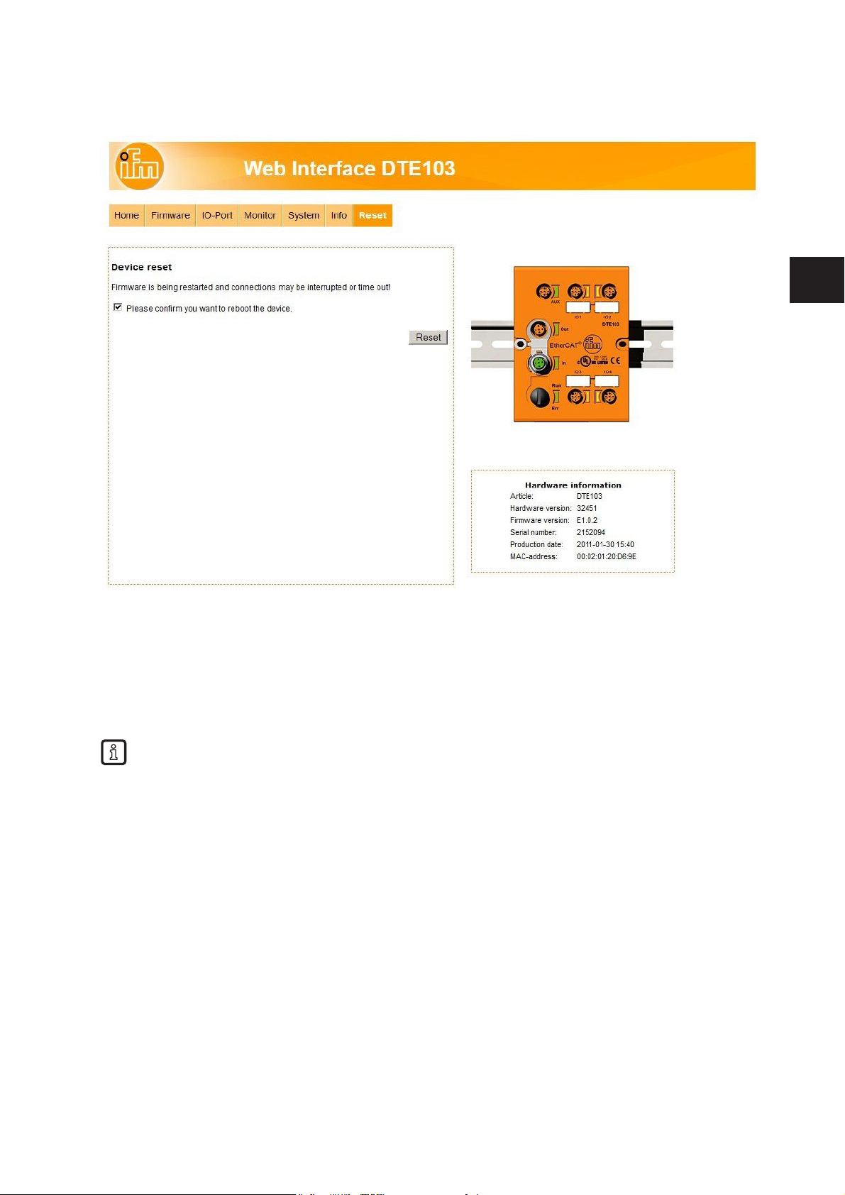
8.8 Tab "Reset"
This menu allows the user to restart the evaluation unit remotely.
If the evaluation unit is restarted, all connections are closed and the outputs are switched off.
To restart the evaluation unit
► check "Please confirm you want to reboot the device"
► Click [submit]
If the evaluation unit does not actualize the Web page, enter the URL of the device in the address
line of the Web client to actualize the display.
Page 26
26
9 Configuration
9.1 Parameter setting of the Ethernet interface
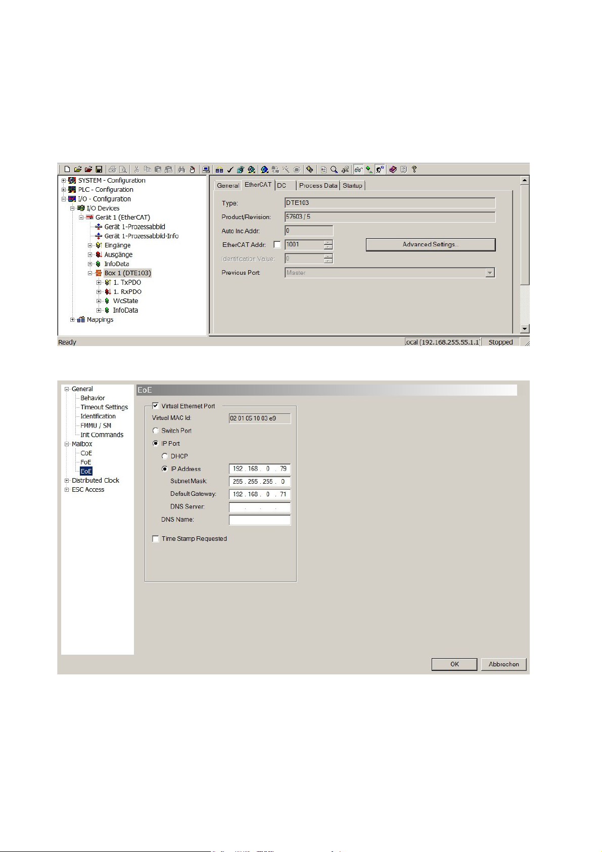
The settings of the Ethernet interface are done over the TwinCAT System Manager.
Screenshots are taken from TwinCAT version 2.11.Select “DTE103” and open Tab “EtherCAT”. Click on
“Advanced Settings”.
Change to entry “Mailbox” -> “EoE” and setup the parameter for the IP address.
Page 27
27
UK
9.2 Determining the MAC address
To determine the MAC adress of the evaluation unit several options are available.
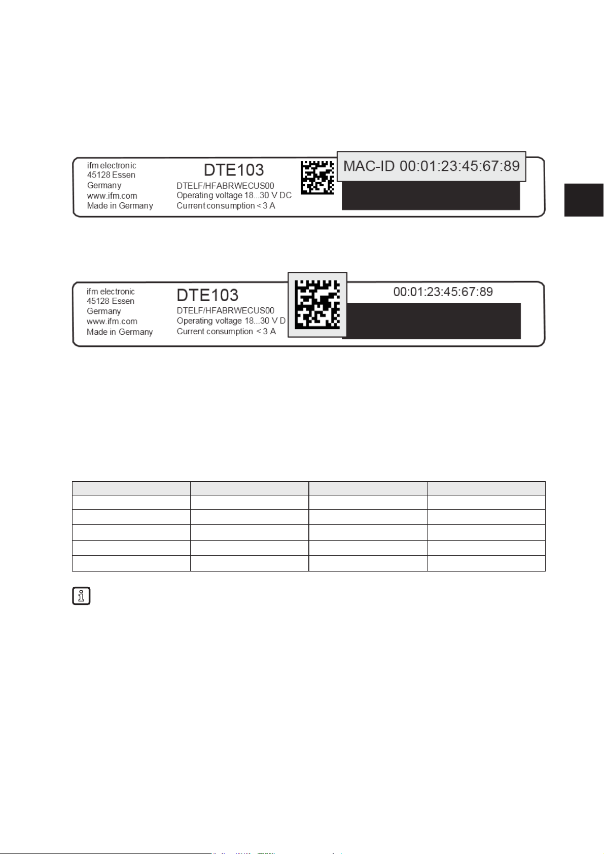
1. Finding the MAC address on the type label
The type lable is located on top of the evaluation unit above the AUX connector.
2. Scanning the MAC address with a data matrix code reader
The code is located on the type label and can be read with any data matrix code scanner.
9.3 Connection concept of the EtherCAT interface
The evaluation unit can be integrated in an EtherCAT network over the connectors "EtherCAT In" and
"EtherCAT Out". The integrated EtherCAT switch allows to build a line structure. An external switch is not
required. The evaluation unit has only one MAC address, enabling the system to address the evaluation
unit with a single IP address. Both Ethernet ports have the same functionality.
9.3.1 Socket connection EtherCAT In and Out
Pin connection of M12 Ethernet socket, D-coded
Signal Name Core colour Pin
TD + Transmission Data + White/orange 1
TD - Transmission Data - Orange 3
RD + Receive Data + White/green 2
RD - Receive Data - Green 4
Screen Shield - Housing
The colours refer to the standard T568B.
9.4 EtherCAT device profile
The device uses the EtherCAT profile “Modular device profile 5001”.
Page 28
28
10 PLC process data image
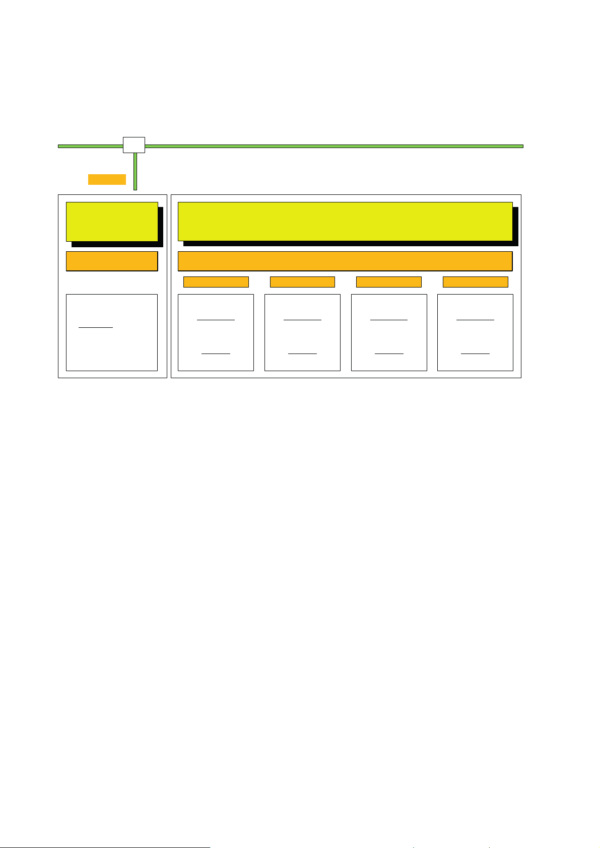
10.1 Address model of the RFID evaluation unit with EtherCAT interface
Device and channel
configuration
SDO 0x4000-4004
Startup settings:
- Ident Unit parametrization
- Channel mode selection
- Channel parametrization
EtherCAT
bus interface
DTE103
Data Exchange Mode
Payload length 4 x 20 bytes = 80 bytes
Tx PDO 0x3000:1
Rx PDO 0x2000:1
Supported mode
Inactive ( 20 Byte In/Out )
Input ( 20 Byte In/Out )
Output ( 20 Byte In/Out )
RWH_RW ( 20 Byte In/Out)
Data content
Data of selected mode
with diagnostics of channel
IO-1 interface IO-2 interface IO-3 interface IO-4 interface
ETHERNET Frame
Configuraon
with
TwinCAT System Manager
Sync Manager 0
Sync Manager 1
Sync Manager 2, 0x1A00, TxPDO (DTE103 -> PLC)
Sync Manager 3, 0x1600, RxPDO (PLC -> DTE103)
Tx PDO 0x3000:2
Rx PDO 0x2000:2
Supported mode
Inactive ( 20 Byte In/Out )
Input ( 20 Byte In/Out )
Output ( 20 Byte In/Out )
RWH_RW ( 20 Byte In/Out)
Data content
Data of selected mode
with diagnostics of channel
Supported mode
Inactive ( 20 Byte In/Out )
Input ( 20 Byte In/Out )
Output ( 20 Byte In/Out )
RWH_RW ( 20 Byte In/Out)
Data content
Data of selected mode
with diagnostics of channel
Supported mode
Inactive ( 20 Byte In/Out )
Input ( 20 Byte In/Out )
Output ( 20 Byte In/Out )
RWH_RW ( 20 Byte In/Out)
Data content
Data of selected mode
with diagnostics of channel
Tx PDO 0x3000:3
Rx PDO 0x2000:3
Tx PDO 0x3000:4
Rx PDO 0x2000:4
The configuration data and the process data of the evaluation unit are transferred over the EtherCAT
connection. The PLC act as requestor, the evaluation unit as responder.
10.1.1 Process data input image
Each IO channel occupies 20 bytes of the PLC process data input, regardless if it is activated or not. Total
size is fixed to 80 bytes.
10.1.2 Process data output image
Each IO channel occupies 20 bytes of the PLC process data output, regardless if it is activated or not.
Total size is fixed to 80 bytes
Page 29
29
UK
11 Parameter setting
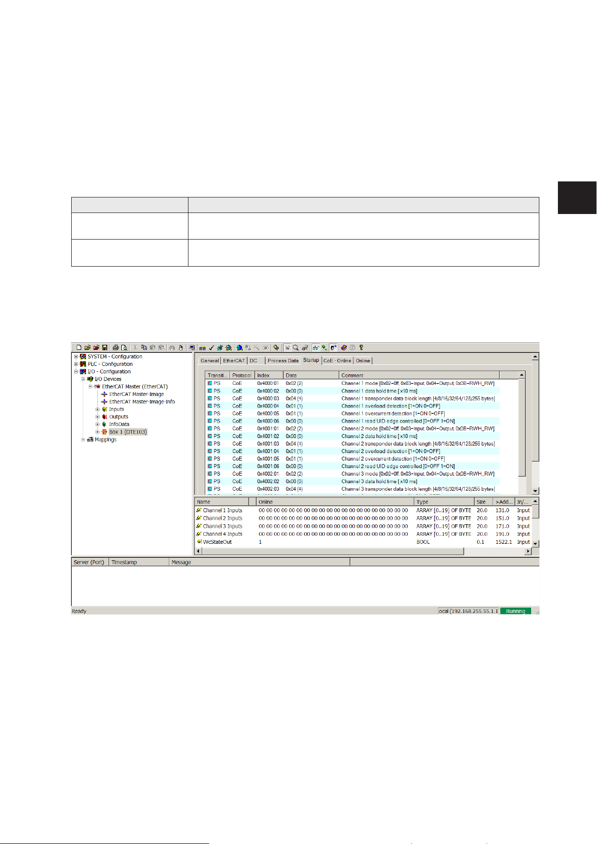
The parameters of the evaluation unit are set via the Startup settings of the device within the TwinCAT
System manager. The 4 IO channels of the RFID evaluation unit can be configured depending on the
application.
11.1 Device parameters
The device-specific parameters can be set in tab “Startup” of the evaluation unit.
11.1.1 Failsafe mode
Failsafe mode Description
Off The IO channel is deactivated if no connection to the EtherCAT controller is
established (default).
On The IO channels remain activated and the outputs keep the state received
last if no connection to the EtherCAT controller is established.
Select line “PS CoE 0x4004:01” in tab “Startup” of the device. Enter the requested value.
11.2 Module setting
Each IO-channel can be configured via the Startup settings of the device within the TwinCAT System
manager. Select the evaluation unit, here named “Box 1”, and open Tab “Startup”.
Page 30
30
11.3 Module parameters
The parameters of the modules Input, Output and RWH_RW can be set.
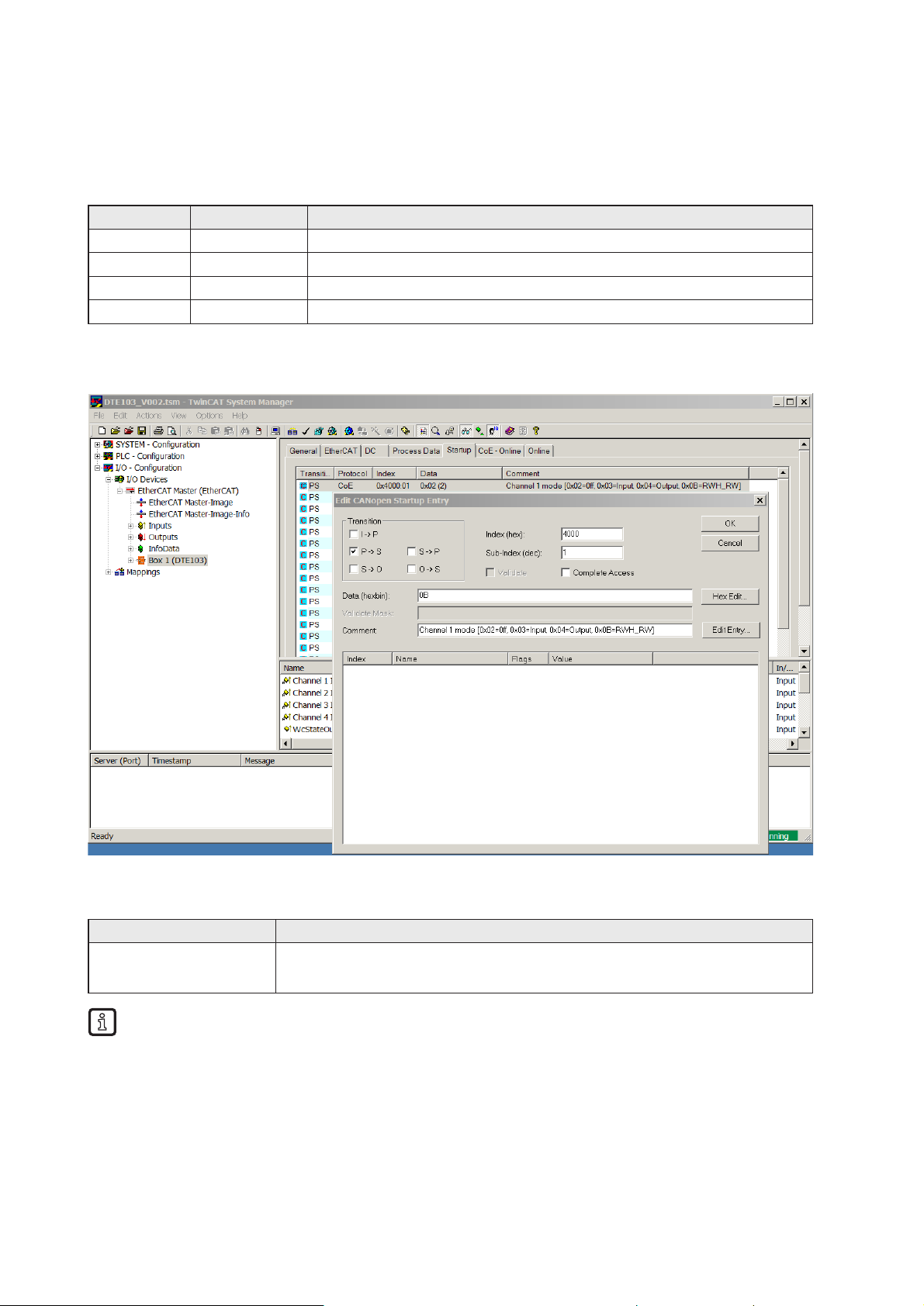
11.3.1 Setup “IO-channel mode”
Data [hex] Module Description
02 Inactive Channel off
03 Input 2 IEC 61131 inputs , terminals C/Qi and I/Q
04 Output 1 IEC 61131 output, 1 IEC 61131 input I/Q
0B RWH_RW RFID read/write head
Select first line “PS CoE 0x4000:01” in tab “Startup” of the device. Set the IO-channel mode by enter the
“CANopen Startup Entry”, field “Data”, of the IO-1 channel.
11.3.2 Setup "Data hold time"
Parameter Description
Data hold time Hold time of the UID and User data information of the RFID tag:
Unit: (milliseconds *10), 0 ms (default)
The value must be input as hexadecimal number.
Example: For 100 ms the setting shall be “0A”
Parameter valid only for IO-channel mode “Input”, “Output” and “RWH_RW”.
Select line 2 “PS CoE 0x4000:02” in tab “Startup” of the device. Enter the request value.
Page 31
31
UK
11.3.3 Setup “Transponder data block length”
Parameter Description
Transponder data block
size
Block size in bytes of the RFID tag:
4/8/16/32/64/128/255
Please refer to the data sheet of the RFID tag for the block size
Only necessary for IO-channel mode “RWH_RW”
The value must be input as hexadecimal number.
Example: For 32 byte the setting shall be “20”
Select line 3 “PS CoE 0x4000:03” in tab “Startup” of the device. Enter the requested value.
11.3.4 Setup “Overload and Overcurrent detection”
With the parameter “Overload detection” the output current at terminal L+ can be controlled.
With the parameter “Overcurrent detection” the output current at terminal C/Qo can be controlled.
Parameter Description
Overload detection On: Overload on terminal L+ of the IO-port is supervised ( default )
The output current is limited to 500...700 mA
Off: Supervision is off
The output current is not supervised and may increase up to 1200
mA. In this case the output driver of the IO-channel is protect against
overtemperature.
Overcurrent detection On: Overcurrent on terminal C/Qo of the IO-port is supervised ( default )
The output current is limited to 500 mA
Off: Supervision is off
The output current is not supervised and may increase up to 600 mA. In this
case the output driver of the IO-channel is protect against overtemperature.
Select line 4 and 5 with “PS CoE 0x4000:04” and “PS CoE 0x4000:05” in tab “Startup” of the device.
Enter the requested value.
The maximum current consumption at terminal AUX + / AUX - may not exceed 3 A.
11.3.5 Setup “Read UID edge controlled”
If the UID of the RFID tag shall be read only when a “Read UID” command is started than the value shall
be set to “01”. (Activate synchronous mode)
If the UID of the RFID tag shall be read continuously without sending a command from the EtherCAT
master the value “00” shall be used. (Activate asynchronous mode)
Parameter valid only for IO-channel mode “RWH_RW”
Parameter Description
UID edge controlled Edge-controlled reading of the UID via bit RD in the control word of the
module RWH_RW
Default: Off
Select line 6 with “PS CoE 0x4000:06” in tab “Startup” of the device. Enter the requested value.
Repeat the setup for all used IO-channels.
Page 32

32
12 Module description
The following functions are available:
● Detection if an RFID tag is in front of the read/write head.
● Control of read/write head to switch on or off the RFID antenna field.
● Read of the Unique Identifier number (UID) of the RFID tag.
● Read of the User data of the RFID tag.
Reading started via control bit “RD”. Maximum read length with one command is 16 bytes. (1)
● Write to the User data of the RFID tag.
Writing started via control bit “WR”. Maximum write length with one command is 16 bytes. (1)
● Write verified to the User data of the RFID tag.
Writing verified started via control bit “WR” and "RD". Maximum write length with one command is
16 bytes. (1)
● Simple diagnostics of the IO-x channels of the evaluation unit.
● Simple notification of evaluation unit diagnostics.
● Remote restart of the evaluation unit
(1) If more data than 16 bytes had to be read or written, the user must repeat the command with changed
offset parameter.
Module name Description Remark
Inactive ( 20 Byte In/Out ) Cyclic transmission High impedance
Input ( 20 Byte In/Out ) Cyclic transmission IEC61131 Input
Output ( 20 Byte In/Out ) Cyclic transmission IEC61131 Output
RWH_RW (20 Byte In/Out) Cyclic command channel Command channel
The PLC input data image and output data image has a size of 4 x 20 bytes = 80 bytes.
Page 33
33
UK
12.1 Module “Inactive”
This module allows the user to:
● switch off an unused process interface IO-1 … IO-4
● read the diagnostic information of the evaluation unit
PLC process data output image (Module Inactive)
Byte no. Bit
7 6 5 4 3 2 1 0
1 0 DR 0 0 0 0 0 0
2 0x00
3 0x00
,, ..
19 0x00
20 0x00
Description byte 1, “Control byte”:
Bit Value Description Remark
DR (1) 0 No read request Data byte 2 … 20 of the PLC process data input image
is set to 0x00.
0 -> 1 Read diagnostics of the evaluation unit 1 Diagnostics read request active DR must be kept on 1 until the diagnostics response is
available.
(1) Diagnostics is only available, if bit “Diag” within the response data is set.
Description Byte 2…20:
Not used. Should be set to 0x00 within the PLC process data output image.
PLC process data input image (Module Inactive)
Byte no. Bit
7 6 5 4 3 2 1 0
1 Diag DR-RDY 0 0 0 0 0 0
2 0x00 / Number of diagnostic events
3 0x00 / Error code byte 1
4 0x00 / Error code byte 2
5 0x00 / Error code byte 3
6 0x00 / Error code byte 4
.. ..
20 Not used
Page 34

34
Description byte 1, “Status byte”:
Bit Value Description Remark
DR-RDY 0 Reading not started or evaluation unit
diagnostics data not ready
-
1 Diagnostics read ready Diagnostics read response from evaluation unit is ready
and available in byte 2 … n.
Diag 0 No diagnostics available -
1 evaluation unit diagnostics occurred Data not yet written in the response buffer. The
response buffer contains still default values 0x00. The
diagnostics data will be copied in the response buffer,
after detecting that the DR control bit.is set within the
control byte.
Description Byte 2, ”Number of diagnostic events”:
Number of diagnostic events.
(0 = No diagnostics, 1…4 = 1…4 diagnostics event(s))
Description Byte 3…n:
If bit “DR-RDY” within the Status byte is set these bytes contain the error codes of the evaluation unit.
Otherwise these bytes are set to default value 0x00 by the evaluation unit.
If more than one diagnostics event is available this is appended. Up to 4 diagnostics messages could be
transferred. Error codes see (→ 14 Error codes of the evaluation unit).
Description Byte (n+1)…20:
Will be set to default value 0x00 by the evaluation unit.
Page 35
35
UK
12.2 Module “Input”
This module allows the user to
● read the binary inputs of the process interface IO-1 … IO-4.
● read the diagnostic information of the evaluation unit.
PLC process data output image (Module Input)
Byte no. Bit
7 6 5 4 3 2 1 0
1 0 DR 0 0 0 0 0 0
2 0x00
3 0x00
,, ..
19 0x00
20 0x00
Description byte 1, “Control byte”:
Bit Value Description Remark
DR (1) 0 No read request Data byte 2 … 20 of the PLC process data input image
is set to 0x00.
0 -> 1 Read diagnostics of the evaluation unit 1 Diagnostics read request active DR must be kept on 1 until the diagnostics response is
available.
(1) Diagnostics is only available, if bit “Diag” within the response data is set.
Description Byte 2…20:
Not used. Should be set to 0x00 within the PLC process data output image.
PLC process data input image (Module Input)
Byte no. Bit
7 6 5 4 3 2 1 0
1 Diag DR-RDY 0 0 OL 0 I/Q C/Qi
2 0x00 / Number of diagnostic events
3 0x00 / Error code byte 1
4 0x00 / Error code byte 2
5 0x00 / Error code byte 3
6 0x00 / Error code byte 4
.. …
20 Not used
Page 36

36
Description byte 1, “Status byte”:
Bit Value Description Remark
C/Qi 0 Input at C/Qi < 8 V The level of C/Qi is measured by hardware
1 Input at C/Qi > 11 V The level of C/Qi is measured by hardware
I/Q 0 Input I/Q < 8 V The level of I/Q is measured by hardware
1 Input I/Q > 11 V The level of I/Q is measured by hardware
OL 0 L+ o.k. Set by hardware
1 Overload on L+ Set by hardware
DR-RDY 0 Reading not started or evaluation unit
diagnostics data not ready
-
1 Diagnostics read ready Diagnostics read response from evaluation unit is ready
and available in byte 2 … 5.
Diag 0 No diagnostics available. -
1 evaluation unit diagnostics occurred Data not yet written in the response buffer. The
response buffer contains still default values 0x00. The
diagnostics data will be copied in the response buffer,
after detecting that the DR control bit.is set within the
control byte.
Description Byte 2, ”Number of diagnostic events”:
Number of diagnostic events.
(0 = No diagnostics, 1…4 = 1…4 diagnostics event(s))
Description Byte 3…n:
If bit “DR-RDY” within the Status byte is set these bytes contain the error codes of the evaluation unit.
Otherwise these bytes are set to default value 0x00 by the evaluation unit.
If more than one diagnostics event is available this is appended. Up to 4 diagnostics messages could be
transferred. Error codes see chapter 14.
Description Byte (n+1)…20:
Will be set to default value 0x00 by the evaluation unit.
Page 37
37
UK
12.3 Module “Output”
This module allows the user to
● read the binary inputs of the process interface IO-1 … IO-4.
● write to binary outputs of the process interface IO-1 … IO-4.
● read the diagnostic information of the evaluation unit.
PLC process data output image (Module Output)
Byte no. Bit
7 6 5 4 3 2 1 0
1 0 DR 0 0 0 HC 0 C/Qo
2 0x00
3 0x00
,, …
19 0x00
20 0x00
Description byte 1, “Control byte”:
Bit Value Description Remark
C/Qo 0 Drive output at C/Qo low -
1 Drive output at C/Qo high -
HC 0 Allow lowside and highside output current
of max. 0.5A at C/Qo
Bit HC only valid on channel IO-3 and channel IO-4.
(Output driver is in Push/Pull mode)
1 Allow highside output current of max. 1A
at C/Qo
Bit HC only valid on channel IO-3 and channel IO-4.
(Output driver is in Push mode)
DR (1) 0 No read request Data byte 2 … 20 of the PLC process data input image
is set to 0x00.
0->1 Read diagnostics of the evaluation unit 1 Diagnostics read request active DR must be kept on 1 until the diagnostics response is
available.
(1) Diagnostics is only available, if bit “Diag” within the response data is set.
Description Byte 2…20:
Not used. Should be set to 0x00 within the PLC process data output image.
PLC process data input image (Module Output)
Byte no. Bit
7 6 5 4 3 2 1 0
1 Diag DR-RDY 0 0 OL HC I/Q C/Qi
2 0x00 / Number of diagnostic events
3 0x00 / Error code byte 1
4 0x00 / Error code byte 2
5 0x00 / Error code byte 3
6 0x00 / Error code byte 4
.. …
20 Not used
Page 38

38
Description byte 1, “Status byte”:
Bit Value Description Remark
C/Qi 0 Level at C/Qo = L The level of C/Qi is not measured, but taken from the
output value C/Qo
1 Level at C/Qo = H The level of C/Qi is not measured, but taken from the
output value C/Qo
I/Q 0 Input I/Q < 8V The level of I/Q is measured by hardware
1 Input I/Q > 11V The level of I/Q is measured by hardware
HC 0 Current of max. 0.5A enabled at C/Qo -
1 Current of max. 1A enabled at C/Qo Only valid on channel IO-3 and IO-4
OL 0 L+ o.k. Set by hardware
1 Overload on L+ Set by hardware
DR-RDY 0 Reading not started or evaluation unit
diagnostics data not ready
-
1 Diagnostics read ready Diagnostics read response from evaluation unit is ready
and available in byte 2 … 5.
Diag 0 No diagnostics available. -
1 evaluation unit diagnostics occurred Data not yet written in the response buffer. The
response buffer contains still default values 0x00. The
diagnostics data will be copied in the response buffer,
after detecting that the DR control bit.is set within the
control byte.
Description Byte 2, ”Number of diagnostic events”:
Number of diagnostic events.
(0 = No diagnostics, 1…4 = 1…4 diagnostics event(s))
Description Byte 3…n:
If bit “DR-RDY” within the Status byte is set these bytes contain the error codes of the evaluation unit.
Otherwise these bytes are set to default value 0x00 by the evaluation unit.
If more than one diagnostics event is available this is appended. Up to 4 diagnostics messages could be
transferred. Error codes see chapter 14.
Description Byte (n+1)…20:
Will be set to default value 0x00 by the evaluation unit.
Page 39
39
UK
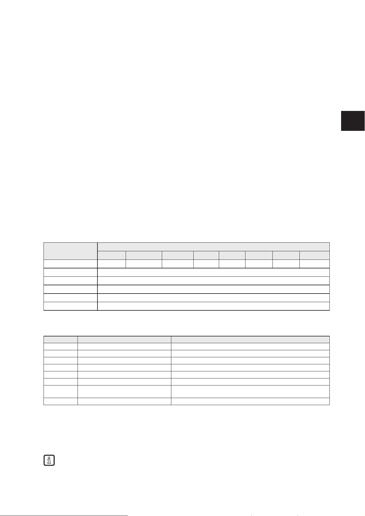
12.4 Module “RWH_RW”, general description
This module allows the user to
● read the UID of the RFID tag over the read/write head at process interface IO-1 … IO-4. Two different
modes are available:
– Read UID once on request (Synchronous mode).
– Read UID automatically whenever the evaluation unit detect a change of the UID data
(Asynchronous mode).
● read the User data of the RFID tag over the read/write head at process interface IO-1 … IO-4. Two
different modes are available:
– Read User data of the RFID tag once on request (Synchronous mode).
– Read User data of the RFID tag automatically whenever the evaluation unit detect a change of the
UID data (Asynchronous mode).
● Write to the User data of the RFID tag over the read/write head at process interface IO-1 … IO-4.
● Write verified to the User data of the RFID tag.
● Read the diagnostic information of the evaluation unit.
● Switch off and on the antenna field of the read/write head
PLC process data output image (Module RWH_RW)
Byte no. Bit
7 6 5 4 3 2 1 0
1 Res DR ER UR RD WR AO Res
2 Data byte 1
3 Data byte 2
,, …
19 Data byte 18
20 Data byte 19
Description Byte 1, “Control byte”:
Bit Bit name Description
0 Res Reserved
1 AO „Antenna field Off“ request
2 WR WRite data to the User data of the RFID tag
3 RD ReaD data from the User data of the RFID tag
4 UR Mode “Access to the UseR data of the RFID tag”
5 ER Mode “Event controlled Reading of User memory of the RFID tag”
6 DR evaluation unit Diagnostics Read, set by the controller to fetch the
diagnostics, signaled by the evaluation unit in the Diag status bit
7 Res Reserved
Remark:
The bits WR, RD, DR are edge controlled bits. The change from state “0->1” activates the command
request. The state “1” forces the evaluation unit to hold the response data or to execute the command
automatically. The state “0” forces the evaluation unit to set the data within the Process data input image
from Byte 2…20 to default value “0x00”.
It is not allowed to the set bit DR with the bits WR or RD or ER simultaneously, because the module
can handle only one command request. Otherwise an error message is created (Diag bit = 1).
Page 40
40
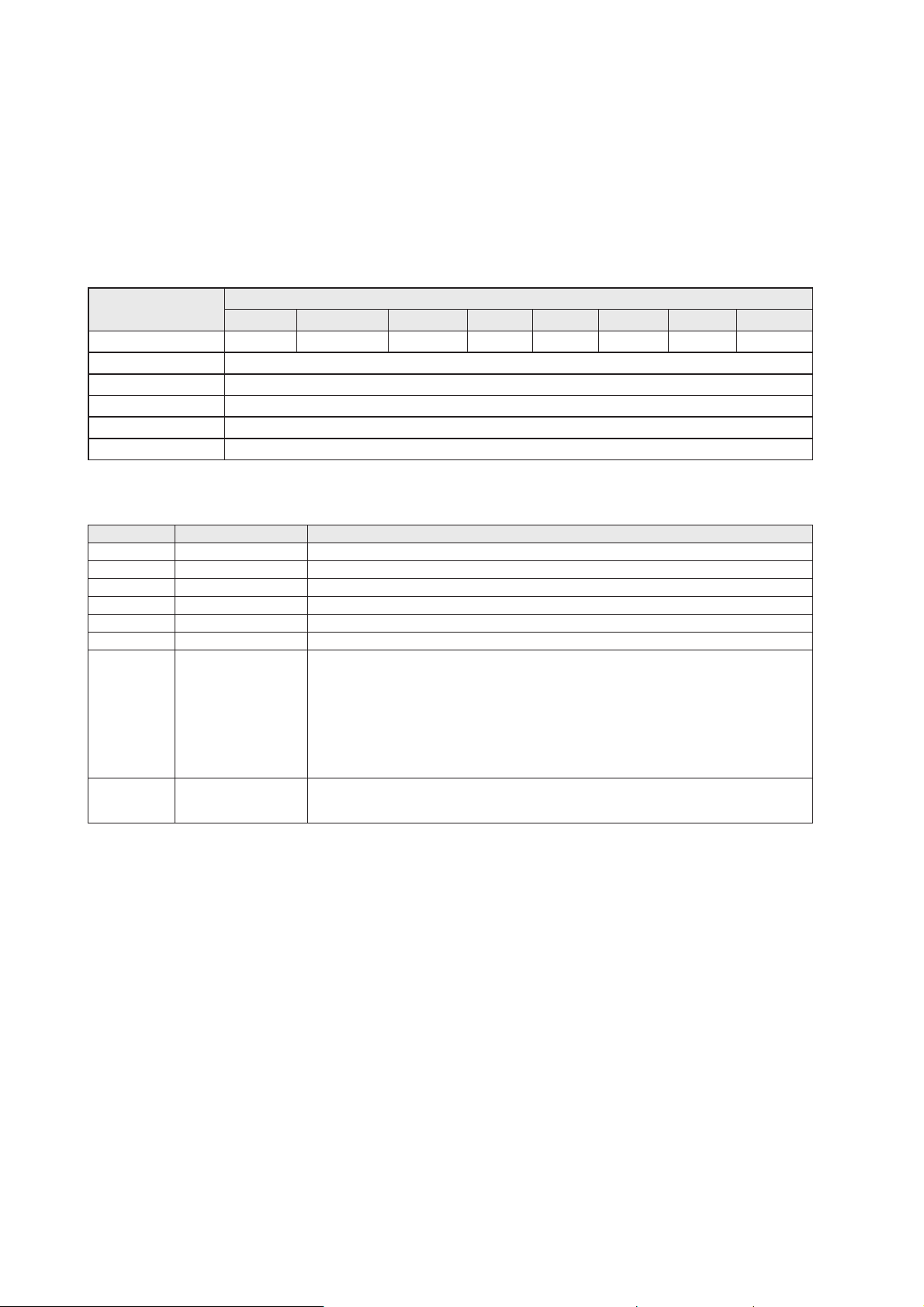
Description Byte 2…20, ”Data byte 1…19”:
Dependent on the selected mode this data memory contains command data to send to the evaluation
unit.
Default value “Control byte”: 0x00
Mode: Read UID automatically, antenna field on
PLC process data input image (Module RWH_RW)
Byte no. Bit
7 6 5 4 3 2 1 0
1 DIAG DR-RDY EA UD RD-RDY WR-RDY AI TP
2 Data byte 1
3 Data byte 2
.. …
19 Data byte 18
20 Data byte 19
Description Byte 1, “Status byte”:
Bit Bit name Description
0 TP RFID tag Present
1 AI Antenna field Inactive
2 WR-RDY WRite to User data of the RFID tag ReaDY
3 RD-RDY ReaD from the User data of the RFID tag ReaDY
4 UD Mode “Access to the User Data of the RFID tag” active
5 EA Mode “Receive User data on Event change Active”
6 DR-RDY Diagnostics Read response ReaDY and available in the response buffer.
Coding:
Byte 2: Number of diagnostic events
Byte 3-6: Diagnostic message 1
Byte 7..10: Diagnostic message 2
Byte 11..14: Diagnostic message 3
Byte 15..18: Diagnostic message 4
7 DIAG Evaluation unit DIAGnostics occurred, but not yet written in the response buffer. The
response buffer contains still RFID tag data. The diagnostics data will be copied in the
response buffer, after detecting that the DR control bit is set by the controller.
Description Byte 2…20, ”Data byte 1…19”:
Dependent on the selected mode this data memory contains the response data read from the evaluation
unit or the diagnostics information.
Page 41
41
UK
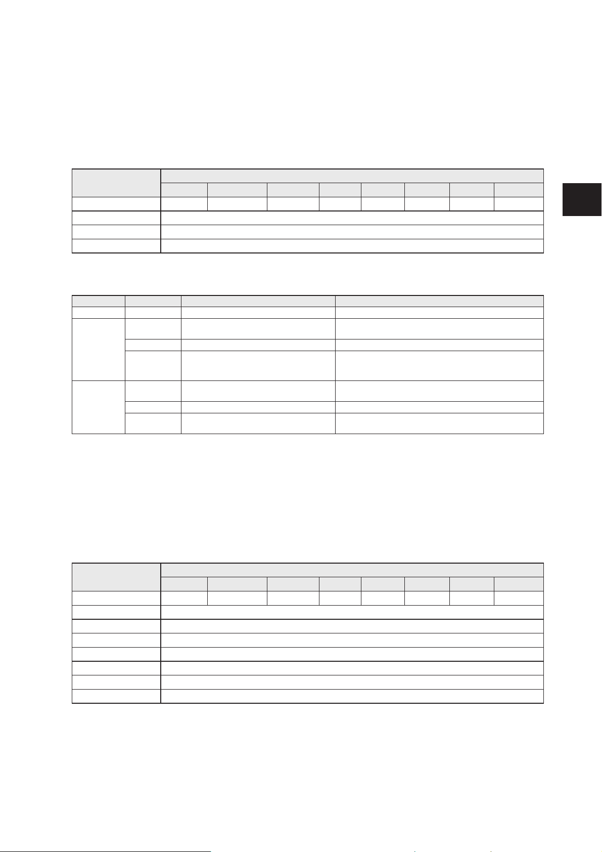
12.5 Module “RWH_RW”, Read UID of the RFID tag synchronously
In this mode the UID of the RFID tag can be read once by setting the bit RD from 0 to 1. This mode is
suitable if the user knows when the RFID tag is present in front of the read/write head. The read UID is
kept in the data bytes 2…18 stable while bit RD is set to 1.
PLC process data output image (Module RWH_RW)
Byte no. Bit
7 6 5 4 3 2 1 0
1 0 DR (2) 0 0 RD (1) 0 AO=0 0
2 Not used
,, ..
20 Not used
Description byte 1, “Control byte”:
Bit Value Description Remark
AO 0 “Antenna field on” request Activate the antenna field
RD (1) 0 UID no read request UID length/data is cleared in data bytes 2…20 of the
PLC process data input
0->1 Edge: UID read request Starts the reading of the UID.
1 UID hold request RD must be kept on 1 until the command response is
available. The UID length/data is transmitted in data
byte 2…20 of the PLC process data input.
DR (2) 0 No read request Data byte 2 … 20 of the process data input image is set
to 0x00
0->1 Read diagnostics of the evaluation unit 1 Diagnostics read request active DR must be kept on 1 until the command response is
available
(1) Bit RD is only evaluated if the channel parameter “UID edge controlled” is set. Otherwise the UID will
be read continuously regardless of the setting of bit RD.
(2) Diagnostics is only available, if bit “Diag” within the response data is set. Otherwise the response data
will return default data “0x00” within byte 2...20. The setting of bit DR to 1 is only allowed when bit RD is
set to 0.
PLC process data input image (Module RWH_RW)
Byte no. Bit
7 6 5 4 3 2 1 0
1 Diag DR-RDY 0 0 RD-RDY 0 AI=0 TP
2 UID data length read
3 UID data byte 1 ( MSBy )
4 UID data byte 2
,, ...
18 UID data byte 16
19 0x00
20 0x00
Page 42

42
Description Byte 1, “Status byte”:
Bit Value Description Remark
TP 0 No RFID tag detected in front of the read/
write head
-
1 RFID tag is detected in front of the read/
write head
Bit is set to 1 as long as the RFID tag is detected by the
Read/write head. With the channel parameter “data hold
time” the status of the bit can be extended.
AI 0 “Antenna field on” request active RD-RDY 0 No read request started or read request
not ready
Data in Byte 2 … 18 is set to default values 0x00
1 Read request from evaluation unit ready Data in Byte 2 … 18 valid.
DR-RDY 0 No diagnostic read request or diagnostic
data not ready.
-
1 Diagnostics read request from evaluation
unit ready.
Error code:
Byte 2: Number of diagnostic events
Byte 3-6: Diagnostic message 1
Byte 7..10: Diagnostic message 2
Byte 11..14: Diagnostic message 3
Byte 15..18: Diagnostic message 4
Diag 0 No error detected -
1 evaluation unit diagnostics available -
Description Byte 2, ”UID data length read”:
UID data length read. Data length of the UID read from RFID tag [bytes].
Remark: If no RFID tag is detected by the read/write head this byte is set to 0x00.
Description Byte 3 … 6/10/14/18, ”UID data byte”:
Read UID of the RFID tag with length of 32/64/96/128 bit. Unused bytes are set to 0x00. If no RFID tag is
detected by the read/write head this data field is set to 0x00.
Description Byte 19 … 20:
Always set to 0x00.
Page 43
43
UK
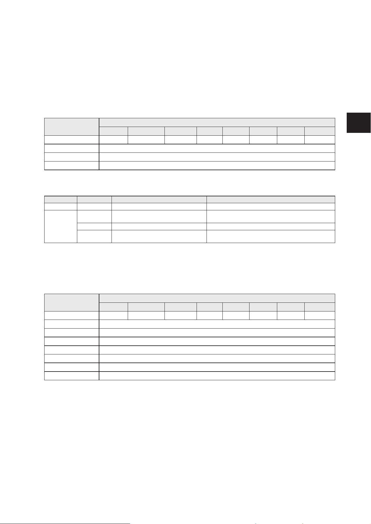
12.6 Module “RWH_RW”, Read UID of the RFID tag asynchronously
In this mode the UID of the RFID tag can be read automatically without sending any read request. This
mode is suitable if the user do not know when the RFID tag is present in front of the read/write head.
Additionally this mode allow the fastest detection of RFID tag cause no command request need to be
send to the evaluation unit. Please note that the UID is transmitted in real time and the PLC cycle time
need to be about factor 2 shorter as the RFID tag is detected by the read/write head.
PLC process data output image (Module RWH_RW)
Byte no. Bit
7 6 5 4 3 2 1 0
1 0 DR (1) 0 0 0 0 AO=0 0
2 Not used
,, ..
20 Not used
Description byte 1, “Control byte”:
Bit Value Description Remark
AO 0 “Antenna field on” request Activate the antenna field
DR (1) 0 No read request Data byte 2 … 20 of the process data input image is set
to 0x00
0->1 Read diagnostics of the evaluation unit 1 Diagnostics read request active DR must be kept on 1 until the command response is
available
(1) Reading of the diagnostics is only possible if ER is set to 0. Diagnostics is only available, if bit “Diag”
within the response data is set. Otherwise the response data will return default data “0x00” within byte
2...20 of the response data.
PLC process data input image (Module RWH_RW)
Byte no. Bit
7 6 5 4 3 2 1 0
1 Diag DR-RDY 0 0 0 0 AI=0 TP
2 UID data length read
3 UID data byte 1 ( MSBy )
4 UID data byte 2
,, ...
18 UID data byte 16
19 0x00
20 0x00
Page 44

44
Description Byte 1, “Status byte”:
Bit Value Description Remark
TP 0 No RFID tag detected in front of the read/
write head
-
1 RFID tag is detected in front of the read/
write head
Bit is set to 1 as long as the RFID tag is detected by the
Read/write head. With the channel parameter “data hold
time” the status of the bit can be extended.
AI 0 “Antenna field on” request active DR-RDY 0 No diagnostic read request or diagnostic
data not ready.
-
1 Diagnostics read request from evaluation
unit ready.
Error code:
Byte 2: Number of diagnostic events
Byte 3-6: Diagnostic message 1
Byte 7..10: Diagnostic message 2
Byte 11..14: Diagnostic message 3
Byte 15..18: Diagnostic message 4
Diag 0 No error detected -
1 evaluation unit diagnostics available -
Description Byte 2, ”UID data length read”:
Data length of the UID read from the RFID tag [bytes].
Remark: If no RFID tag is detected by the read/write head this byte is set to 0x00. The data length is held
according to the setting of the channel parameter “Data Hold Time”
Description Byte 3 … 6/10/14/18, ”UID data byte”:
Read UID of the RFID tag with length of 32/64/96/128 bit. Unused bytes are set to 0x00. If no RFID tag is
detected by the read/write head this data field is set to 0x00.
Remark: . UID data bytes are held according to the setting of the channel parameter “Data Hold Time”
Description Byte 19 … 20:
Always set to 0x00.
Page 45
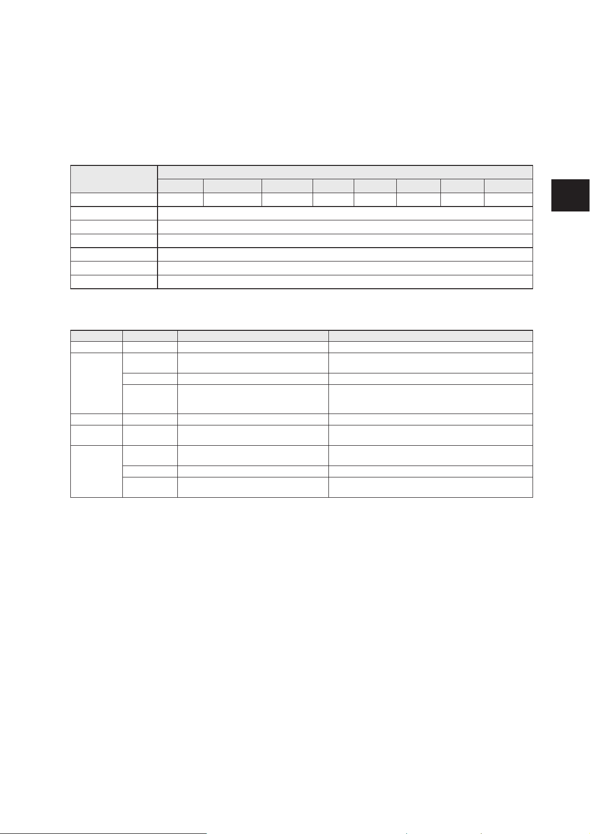
45
UK
12.7 Module “RWH_RW”, Read User data of the RFID tag synchronously
In this mode the User data of the RFID tag can be read edge controlled by setting the bit RD from 0 to 1.
This mode is suitable if the user know when the RFID tag is present in front of the read/write head. The
read User data is kept in the data bytes 2…18 stable while bit RD is set to 1.
PLC process data output image (Module RWH_RW)
Byte no. Bit
7 6 5 4 3 2 1 0
1 0 DR (3) ER=0 UR=1 (1) RD (2) 0 AO=0 0
2 Read data length
3 16 bit start address [D15…D8]
4 16 bit start address [D7…D0]
5 Not used
,,
20 Not used
Description Byte 1, “Control byte”:
Bit Value Description Remark
AO 0 “Antenna field on” request inactive Activate the antenna field.
RD (2) 0 No read request of User data User data length/data is cleared in data byte 2…20 of
the PLC process data input image.
0->1 edge: User data read request Starts the reading of the User data.
1 User data hold request RD must be kept on 1 until the command response is
available. The User data length/data is transmitted in
data byte 2…20 of the PLC process data input image.
UR (1) 1 Mode “User data” selected Must be set to 1 to access the User data of the RFID tag
ER 0 Mode “Read user data synchronously”
selected
Must be set to 0 for reading the User data synchronously
DR (3) 0 No read request Data byte 2 … 20 of the process data input image is set
to 0x00.
0->1 Read diagnostics of the evaluation unit 1 Diagnostics read request active DR must be kept on 1 until the command response is
available.
(1) Mode can be changed every time if bit “RD” and “DR” is set to 0 => no command active.
(2) A simultaneously activation of bit DR and RD is not allowed!
(3) Reading of the diagnostics is only possible if bit RD is set to 0. Diagnostics is only available, if bit
“Diag” within the response data is set. Otherwise the response data will return default data “0x00” within
byte 2...20 of the response data.
Description Byte 2, ”Read data length”:
Read data length, limited to a maximum number of 16 bytes.
Description Byte 3... 4, ”16 bit start address”:
Start address of the RFID tag User data where the data has to be read from.
Description Byte 5... 20, ”Not used ”:
These bytes are ignored.
Page 46
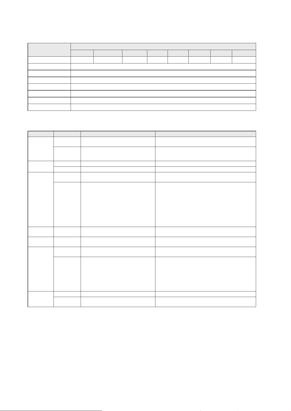
46
PLC process data input image (Module RWH_RW)
Byte no. Bit
7 6 5 4 3 2 1 0
1 Diag DR-RDY EA=0 UD=1 RD-RDY 0 AI TP
2 Read data length
3 Read data byte 1
4 Read data byte 2
,, ...
18 Read data byte 16
19 0x00
20 0x00
Description Byte 1, “Status byte”:
Bit Value Description Remark
TP 0 No RFID tag detected in front of the
read/write head
-
1 RFID tag is detected in front of the read/
write head
Bit is set to 1 as long as the RFID tag is detected by the
Read/write head. With the channel parameter “data hold
time” the status of the bit can be extended.
AI 0 “Antenna field on” request active -
1 “Antenna field off” request active -
RD-RDY 0 No command request detected or
command execution active
Read length / Read data byte is cleared in data byte
2…17 of the PLC process data input image.
1 Command execution is ready. Diag bit is not set:
Command execution ok.
Read length / Read data byte is set in data byte 2…17
of the PLC process data input image.
Diag bit is set:
Command execution not ok.
Read length / Read data bytes are set to zero.
UD 1 Mode “Read/write used data of the RFID
tag” active
Feedback of the selected mode.
EA 0 Mode “Receive User data of the RFID
tag on request” active
Feedback of the selected mode.
DR-RDY 0 No diagnostic read request or diagnostic
data not ready.
-
1 Diagnostics read request from evaluation
unit ready.
Error code:
Byte 2: Number of diagnostic events
Byte 3-6: Diagnostic message 1
Byte 7..10: Diagnostic message 2
Byte 11..14: Diagnostic message 3
Byte 15..18: Diagnostic message 4
Diag 0 No error detected -
1 evaluation unit diagnostics available Maybe channel related or channel independent error
occurred.
Description Byte 2, ”Read data length”:
Read data length
Description Byte 3... 20, ”Read data byte 1 … 16”:
In mode “User data” this data area contains the data of the User data of the RFID tag. Unused bytes are
set to 0x00.
In read diagnostics mode this data area contains detailed error codes.
Page 47
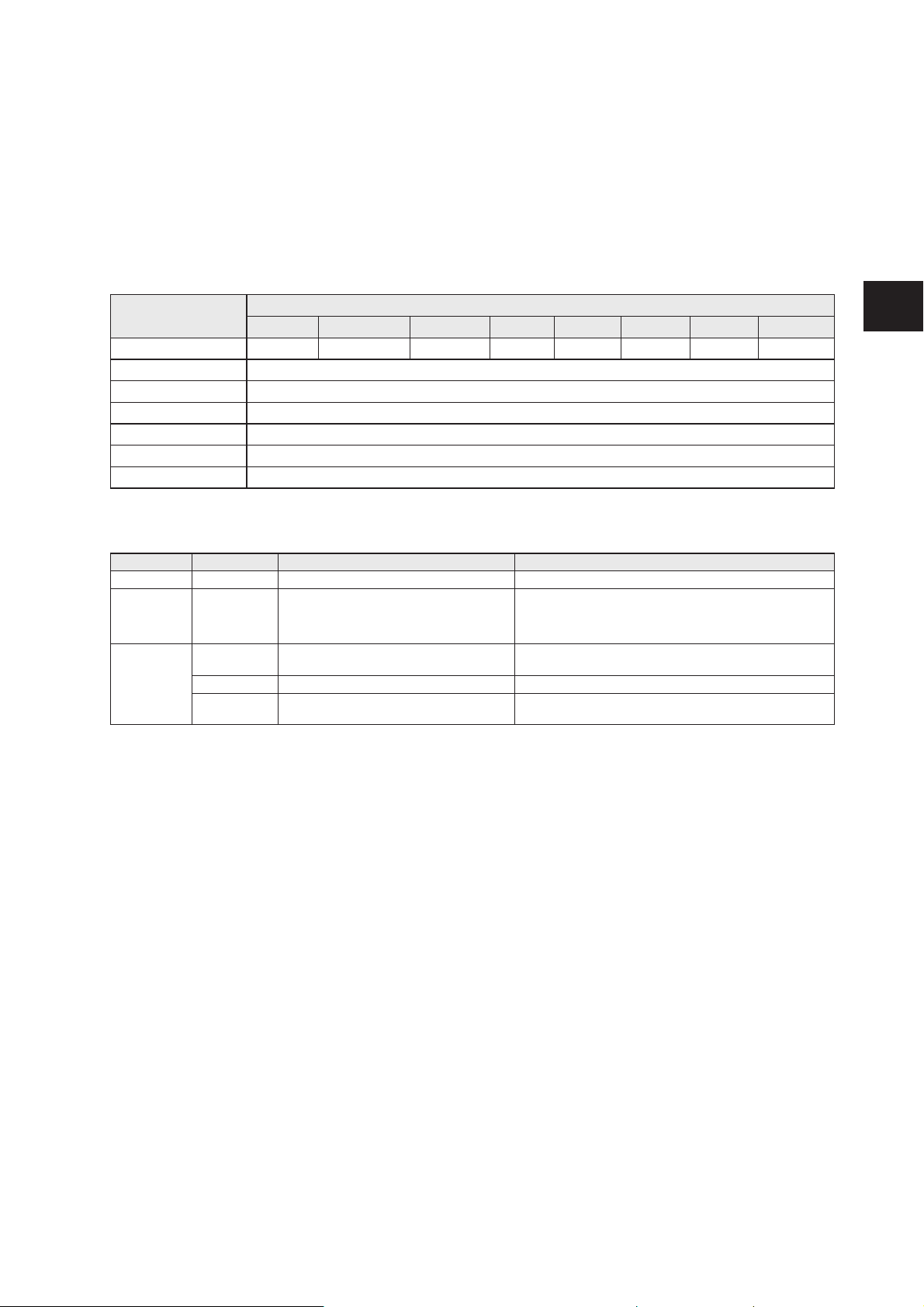
47
UK
12.8 Module “RWH_RW”, Read User data of the RFID tag asynchronously
In this mode the User data of the RFID tag can be read automatically without sending any read request.
This mode is suitable if the user know when the RFID tag is present in front of the read/write head.
Additionally this mode allow the fastest detection of RFID tag cause no command request need to be
send to the evaluation unit. Please note that the User data is transmitted in real time and the PLC cycle
time need to be about factor 2 shorter as the RFID tag is detected by the read/write head.
PLC process data output image (Module RWH_RW)
Byte no. Bit
7 6 5 4 3 2 1 0
1 0 DR (3) ER=1 (2) UR=1 (1) RD=1 (2) 0 AO=0 0
2 Read data length
3 16 bit start address [D15…D8]
4 16 bit start address [D7…D0]
5 Not used
,,
20 Not used
Description Byte 1, “Control byte”:
Bit Value Description Remark
AO 0 “Antenna field on” request inactive Activate the antenna field
RD (2)
UR (1)
ER (2)
1 Mode “Receive User data automatically”
selected
(1) Must be set to 1 to access the User data of the RFID
tag
DR (3) 0 No read request Data byte 2 … 20 of the process data input image is set
to 0x00.
0->1 Read diagnostics of the evaluation unit 1 Diagnostics read request active DR must be kept on 1 until the command response is
available.
(1) Mode can be changed every time if bit “RD”, “ER” and “DR” is set to 0 => no command active.
(2) If bit ER and bit RD is set to 1 a reading process of the User data of the RFID tag is started when a
change of the bit TP is detected. So the user gets only a message from the evaluation unit if the state of
the RFID tag changes from “not present to present” and from “present to not present”. This help to limit
the requests which are needed to be send from the PLC.
(3) Reading of the diagnostics is only possible if ER und RD is set to 0. Diagnostics is only available, if bit
“Diag” within the response data is set. Otherwise the response data will return default data “0x00” within
byte 2...20 of the response data.
Description Byte 2, ”Read data length”:
Read data length, limited to a maximum number of 16 bytes.
Description Byte 3... 4, ”16 bit start address”:
Start address of the RFID tag User data where the data has to be read from.
Description Byte 5... 20, ”Not used ”:
These bytes are ignored.
Page 48
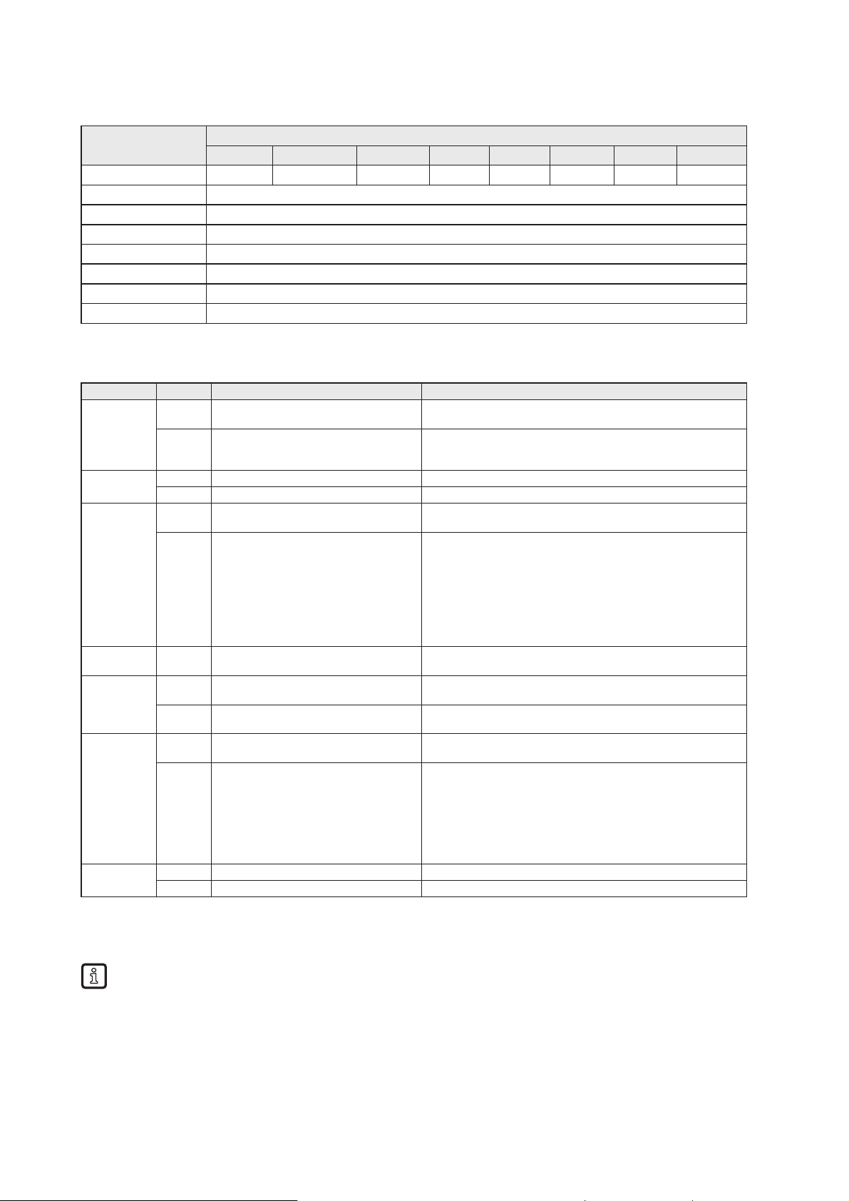
48
PLC process data input image (Module RWH_RW)
Byte no. Bit
7 6 5 4 3 2 1 0
1 Diag DR-RDY EA UD=1 RD-RDY 0 AI TP
2 Read data length
3 Read data byte 1
4 Read data byte 2
,, ...
18 Read data byte 16
19 0x00
20 0x00
Description Byte 1, “Status byte”:
Bit Value Description Remark
TP 0 No RFID tag detected in front of the
read/write head
-
1 RFID tag is detected in front of the
read/write head
Bit is set to 1 as long as the RFID tag is detected by the Read/
write head. With the channel parameter “data hold time” the
status of the bit can be extended.
AI 0 “Antenna field on” request active -
1 “Antenna field off” request active -
RD-RDY 0 No command request detected or
command execution active
Read length / Read data byte is cleared in data byte 2…17 of
the PLC process data input image.
1 Command execution is ready. Diag bit is not set:
Command execution ok.
Read length / Read data byte is set in data byte 2…17 of the
PLC process data input image.
Diag bit is set:
Command execution not ok.
Read length / Read data bytes are set to zero.
UD 1 Mode “Read/write used data of the
RFID tag” active
Feedback of the selected mode.
EA 0 Mode “Receive User data of the RFID
tag on request” active
-
1 Mode “Message controlled reception of
the User data of the RFID tag” actives
-
DR-RDY 0 No diagnostic read request or
diagnostic data not ready.
-
1 Diagnostics read request from
evaluation unit ready.
Error code:
Byte 2: Number of diagnostic events
Byte 3-6: Diagnostic message 1
Byte 7..10: Diagnostic message 2
Byte 11..14: Diagnostic message 3
Byte 15..18: Diagnostic message 4
Diag 0 No error detected -
1 evaluation unit diagnostics available Maybe channel related or channel independent error occurred.
Description Byte 2, ”Read data length”:
Read data length.
The data length is held according to the setting of the channel parameter “Data Hold Time”.
Description Byte 3... 20, ”Read data byte 1 … 16”:
This data area contains the data of the User data of the RFID tag. Unused bytes are set to 0x00.
In read diagnostics mode this data area contains detailed error codes.
The User data are held according to the setting of the channel parameter “Data Hold Time”.
Page 49
49
UK
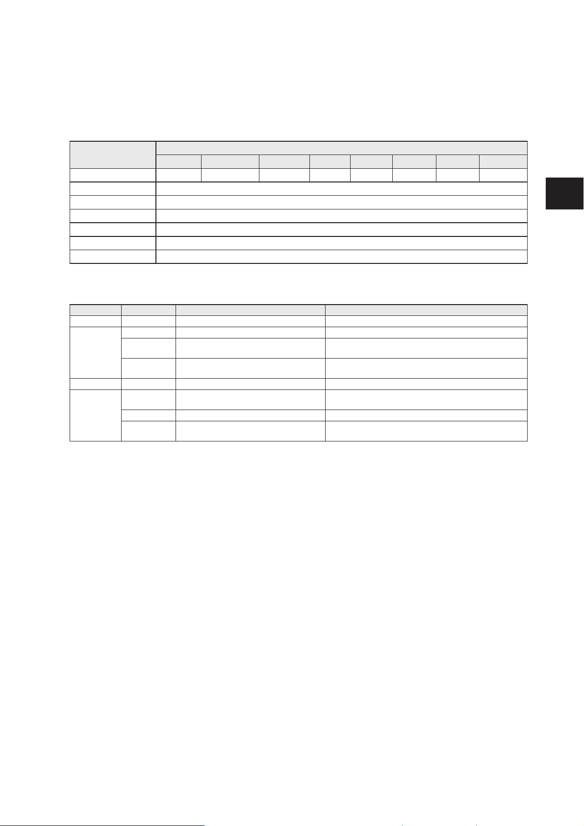
12.9 Module “RWH_RW”, Write User data of the RFID tag
In this mode the User data of the RFID tag can be written.
PLC process data output image (Module RWH_RW)
Byte no. Bit
7 6 5 4 3 2 1 0
1 0 DR (3) 0 UR=1 (1) 0 WR (2) AO=0 0
2 Write data length
3 16 bit start address [D15…D8]
4 16 bit start address [D7…D0]
5 Write data byte 1
,, ..
20 Write data byte 16
Description Byte 1, “Control byte”:
Bit Value Description Remark
AO 0 “Antenna field on” request active Activate the antenna field.
WR (2) 0 No write request -
0->1 Write “user data to the RFID tag” request Data byte 5 … 20 is written to the User data of the RFID
tag.
1 Write request active WR must be kept on 1 until the command response is
available.
UR (1) 1 Mode “User data” selected Must be set to 1 to access the User data of the RFID tag
DR (3) 0 No read request Data byte 2 … 20 of the process data input image is set
to 0x00.
0->1 Read diagnostics of the evaluation unit 1 Diagnostics read request active DR must be kept on 1 until the command response is
available.
(1) Mode can be changed every time if bit DR, WR = 0 (no command active.)
(2) A simultaneously activation of bit DR and WR is not allowed!
(3) Diagnostics is only available, if bit “Diag” within the response data is set. A simultaneously activation
of bit DR with bit WR not allowed! Otherwise the evaluation unit will return default data “0x00” within byte
2...20 of the response data.
Description Byte 2, ”Write data length”:
Write data length, limited to a maximum number of 16 bytes.
Description Byte 3... 4, ”16 bit start address”:
Start address of the RFID tag User data where the data has to be written to.
Description Byte 5... 20, ”Write data byte”:
In write mode the data to be written has to be copied in this data area. (Write data bytes 1 … 16)
Page 50
50
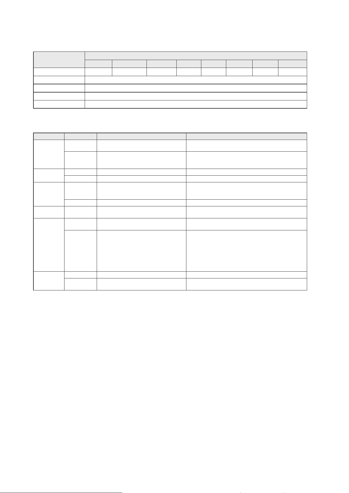
PLC process data input image (Module RWH_RW)
Byte no. Bit
7 6 5 4 3 2 1 0
1 Diag DR-RDY 0 UD=1 0 WR-RDY AI TP
2 Write data length
3 0x00
,, ...
20 0x00
Description Byte 1, “Status byte”:
Bit Value Description Remark
TP 0 No RFID tag detected in front of the read/
write head
-
1 RFID tag is detected in front of the read/
write head
Bit is set to 1 as long as the RFID tag is detected by the
Read/write head. With the channel parameter “data hold
time” the status of the bit can be extended.
AI 0 “Antenna field on” request active -
1 “Antenna field off” request active -
WR-RDY 0 No command request detected or
command execution active or error
occurred.
-
1 Command execution is ready. -
UD 1 Mode “Write User data to the RFID tag”
active
Feedback of the selected mode.
DR-RDY 0 No diagnostic read request or diagnostic
data not ready.
-
1 Diagnostics read request from evaluation
unit ready.
Error code:
Byte 2: Number of diagnostic events
Byte 3-6: Diagnostic message 1
Byte 7..10: Diagnostic message 2
Byte 11..14: Diagnostic message 3
Byte 15..18: Diagnostic message 4
Diag 0 No error detected -
1 evaluation unit diagnostics available Maybe channel related or channel independent error
occurred.
Description Byte 2, ”Write data length”:
Write data length. If the write data length matches to the write data length in the command response and
bit Diag is set to 0 the write process could be finished without failure.
Description Byte 3... 20:
In write mode this bytes are set 0x00.
In read diagnostics mode this data area contains detailed error codes.
Page 51
51
UK
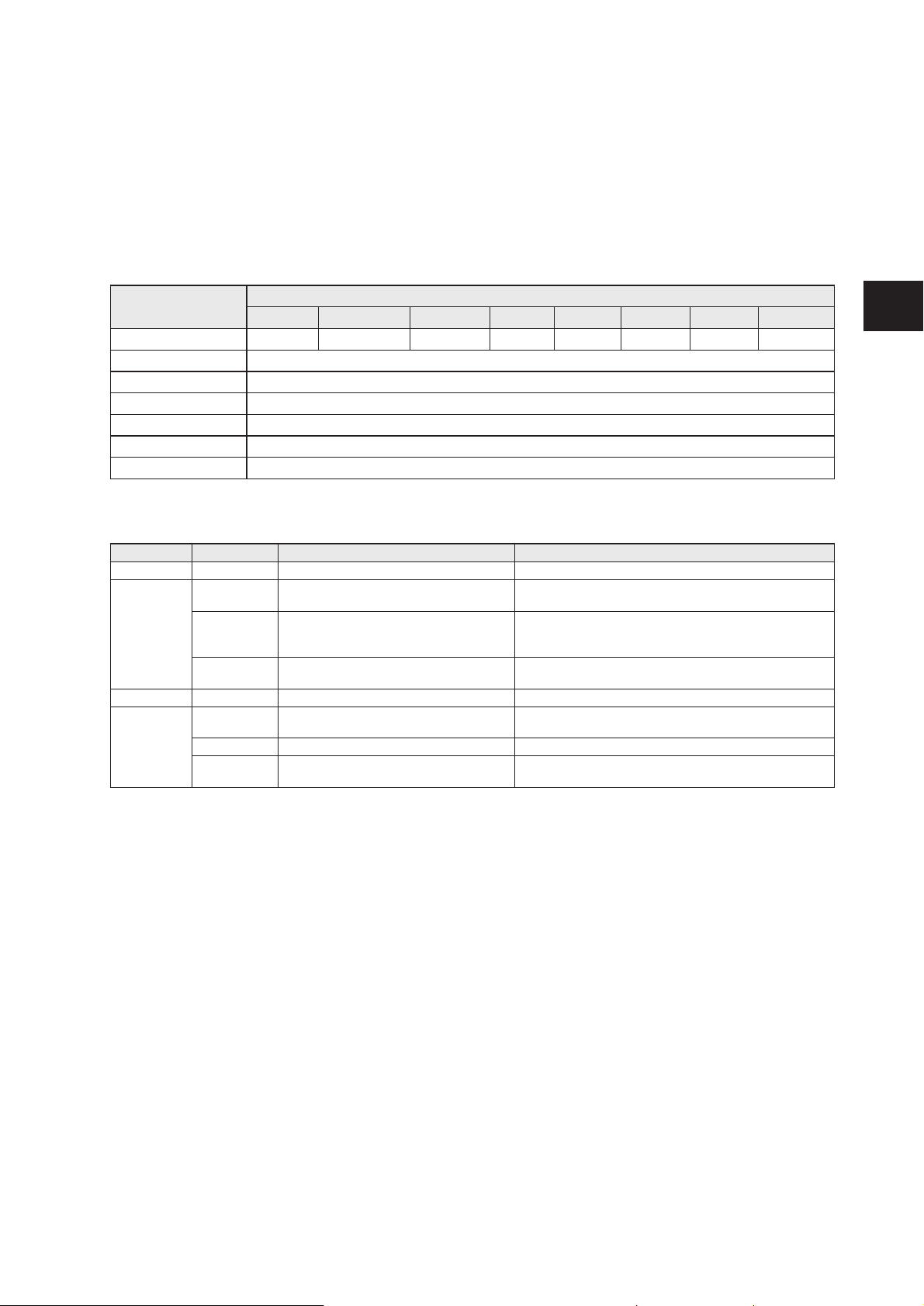
12.10 Module “RWH_RW”, Write verified User data of the RFID tag
In this mode the User data of the RFID tag can be written and read back with one command request.
In the first step the command data is written to the RFID tag, in the second step it is read back from the
RFID tag. In the third step the evaluation unit compares the written data with the read data and sends
back the result to the PLC.
PLC process data output image (Module RWH_RW)
Byte no. Bit
7 6 5 4 3 2 1 0
1 0 DR (3) 0 UR=1 (1) RD (2) WR (2) AO=0 0
2 Write data length
3 16 bit start address [D15…D8]
4 16 bit start address [D7…D0]
5 Write data byte 1
,, ..
20 Write data byte 16
Description Byte 1, “Control byte”:
Bit Value Description Remark
AO 0 “Antenna field on” request active Activate the antenna field.
WR (2)
RD (2)
0 No write verified request active Data byte 2 … 20 of the process data input image is set
to 0x00.
0->1 Write verified to the “user data of the
RFID tag” request
Data byte 5 … 20 are written to the User data of the
RFID tag. Afterwards the data bytes are read back from
the RFID tag.
1 Write verified request active WR must be kept on 1 until the command response is
available.
UR (1) 1 Mode “User data” selected Must be set to 1 to access the User data of the RFID tag
DR (3) 0 No read request Data byte 2 … 20 of the process data input image is set
to 0x00.
0->1 Read diagnostics of the evaluation unit 1 Diagnostics read request active DR must be kept on 1 until the command response is
available.
(1) Mode can be changed every time if bit DR, WR = 0 (no command active.)
(2) Bits WR and RD must be set simultaneously in the command request.
(3) Diagnostics is only available, if bit “Diag” within the response data is set. A simultaneously activation
of bit DR with bits WR and RD is not allowed! Otherwise the evaluation unit will return default data “0x00”
within byte 2...20 of the response data.
Description Byte 2, ”Write data length”:
Write data length, limited to a maximum number of 16 bytes.
Description Byte 3... 4, ”16 bit start address”:
Start address of the RFID tag User data where the data has to be written to.
Description Byte 5... 20, ”Write data byte”:
In write mode the data to be written has to be copied in this data area. (Write data bytes 1 … 16)
Page 52

52
PLC process data input image (Module RWH_RW)
Byte no. Bit
7 6 5 4 3 2 1 0
1 Diag DR-RDY 0 UD=1 RD-RDY WR-RDY AI TP
2 Write data length
3 0x00
,, ...
20 0x00
Description Byte 1, “Status byte”:
Bit Value Description Remark
TP 0 No RFID tag detected in front of the read/
write head
-
1 RFID tag is detected in front of the read/
write head
Bit is set to 1 as long as the RFID tag is detected by the
Read/write head. With the channel parameter “data hold
time” the status of the bit can be extended.
AI 0 “Antenna field on” request active -
1 “Antenna field off” request active WR-RDY
RD-RDY
0 No command request detected or
command execution active.
-
1 Command execution is ready. Result of the comparison is given back in byte 2.
UD 1 Mode “Write User data of the RFID tag”
active
Feedback of the selected mode.
DR-RDY 0 No diagnostic read request or diagnostic
data not ready.
-
1 Diagnostics read request from evaluation
unit ready.
Error code:
Byte 2: Number of diagnostic events
Byte 3-6: Diagnostic message 1
Byte 7..10: Diagnostic message 2
Byte 11..14: Diagnostic message 3
Byte 15..18: Diagnostic message 4
Diag 0 No error detected -
1 evaluation unit diagnostics available Maybe channel related or channel independent error
occurred.
Description Byte 2, ”Read data length”:
If the comparison of the written and read data is successful the read data length is identical to the write
data length.
Description Byte 3... 20:
These bytes contain the User data read back from the RFID tag.
In read diagnostics mode this data area contains detailed error codes.
Page 53
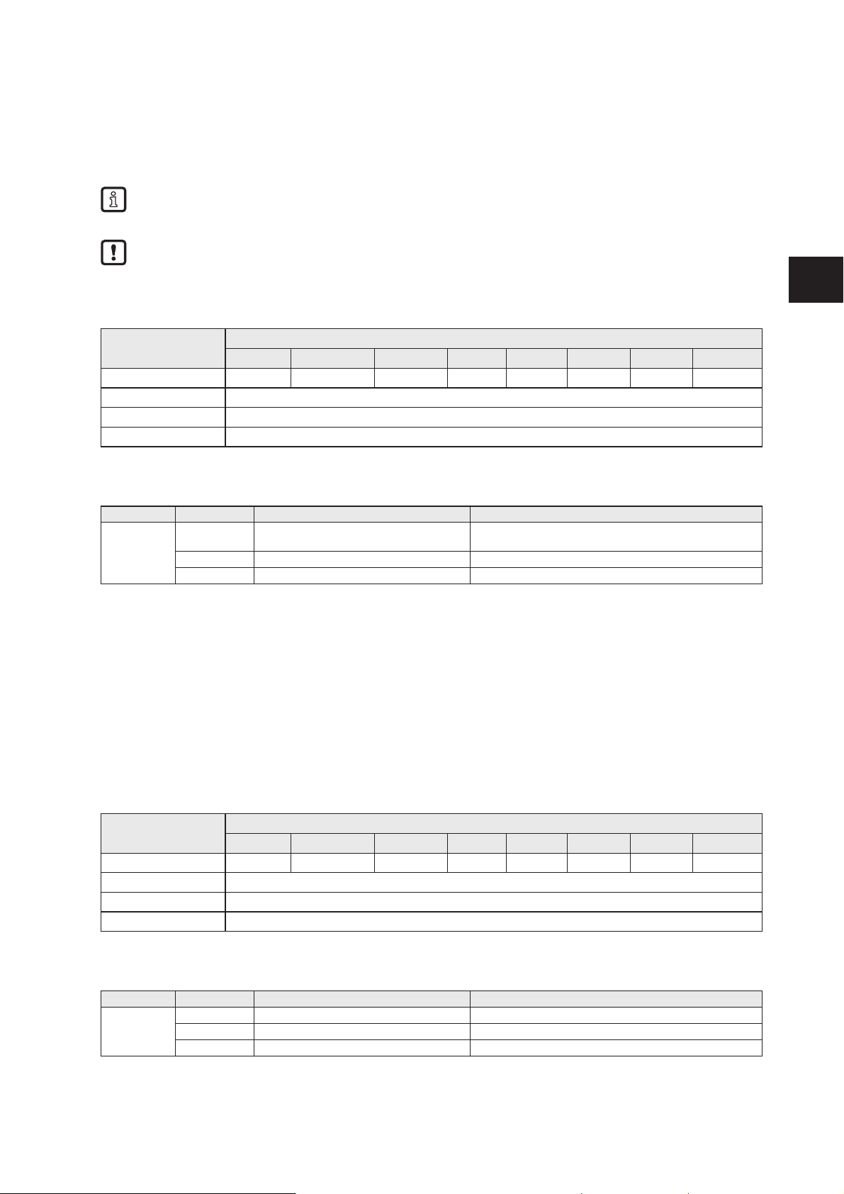
53
UK
12.11 Restart of the evaluation unit
The evaluation unit can be remotely restarted.
The device shut off the fieldbus interface and the IO ports and execute than a power on cycle.
The command can be executed in all modules.
The control and status byte must have value 0x0 before the command is started.
PLC process data output image (Command Restart)
Byte no. Bit
7 6 5 4 3 2 1 0
1 1 1 1 1 1 1 1 1
2 Restart delay time [ms*10]
,, …
20 0x00
Description Byte 1, “Control byte”:
Bit Value Description Remark
D0...D7 0 No restart request Dependent of the activated module, the response data
may contain RFID tag data
0->1 Restart request initiated 1 Restart request active -
Description Byte 2:
0x0 = Restart evaluation unit immediately (Default value)
0x1 .. 0xFF = Restart delay time. Time in [ms*10]
Description Byte 3…20:
Not used. Should be set to 0x00 within the PLC process data output image.
PLC process data input image (Command Restart)
Byte no. Bit
7 6 5 4 3 2 1 0
1 1 1 1 1 1 1 1 1
2 Restart delay time [ms*10]
,, …
20 0x00
Description Byte 1, “Status byte”:
Bit Value Description Remark
D0...D7 0 No restart active -
0->1 Restart initiated 1 Restart active -
Page 54

54
Description Byte 2:
0x0 .. 0xFF Actualized restart delay time [ms*10]. Value is decremented from “Restart delay time” set in
Control byte to 0x0. After that, the restart sequence is executed.
Description Byte 3…20:
Not used. Set to default value 0x0 by the evaluation unit.
Page 55
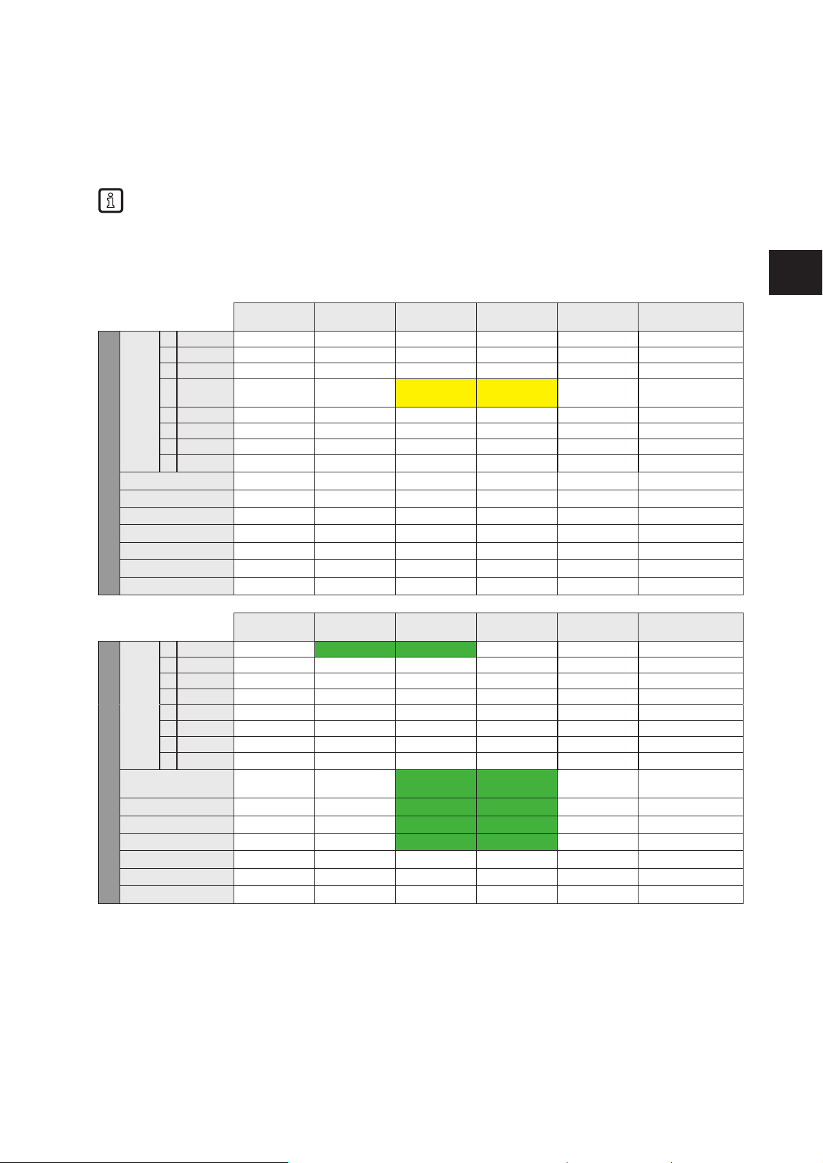
55
UK
13 Data frame examples
In the following examples the evaluation unit is configured for 2 Read/write heads at channel IO-1 and
channel IO-2. The Read/write heads are connected on both channels. Channel 3 and channel 4 are
unconnected.
The values shown in the payload traffic view are in hexadecimal notation. 30 = 0x30 = 48 decimal.
13.1 Read UID on request (synchronous mode)
13.1.1 Command sequence view
Step 0:
no tag in field
Step 1:
tag in field
Step 2:
tag still in field
Step 3: no tag
in field
Step 4: no tag
in field
Remark
PLC process data output
Byte 1
0 0 0 0 0 0 0
1 AO 0 0 0 0 0
2 WR 0 0 0 0 0
3 RD 0 0 1 1 0 Set RD to 1 when
TP = 1 is detected
4 UR 0 0 0 0 0
5 ER 0 0 0 0 0
6 DR 0 0 0 0 0
7 0 0 0 0 0 0
Byte 2 0x00 0x00 0x00 0x00 0x00
Byte 3 0x00 0x00 0x00 0x00 0x00
Byte 4 0x00 0x00 0x00 0x00 0x00
Byte 5 0x00 0x00 0x00 0x00 0x00
... … … … … …
Byte 19 0x00 0x00 0x00 0x00 0x00
Byte 20 0x00 0x00 0x00 0x00 0x00
Step 0:
no tag in field
Step 1:
tag in field
Step 2:
tag still in field
Step 3: tag left
the field
Step 4: no tag
in field
Remark
PLC process data input
Byte 1
0 TP 0 1 (1) 1 0 0
1 AI 0 0 0 0 0
2 WR-RDY 0 0 0 0 0
3 RD-RDY 0 0 0 0 0
4 UD 0 0 0 0 0
5 EF 0 0 0 0 0
6 DR-RDY 0 0 0 0 0
7 Diag 0 0 0 0 0
Byte 2 (UID length) 0x00 0x00 0x04 0x04 0x00 Data is hold until
RD is set to 0
Byte 3 (UID data) 0x00 0x00 0xE0 (2) 0xE0 0x00
Byte 4 (UID data) 0x00 0x00 0x04 0x04 0x00
Byte 5 (UID data) 0x00 0x00 0x01 0x01 0x00
… … … … … …
Byte 19 0x00 0x00 0x00 0x00 0x00
Byte 20 0x00 0x00 0x00 0x00 0x00
(1) TP bit indicate that the RFID tag is detected by the Read/write head.
(2) UID data, the length is dependent from the RFID tag (125kHz = 4 Byte; 13,56 MHz = 8 Byte).
Page 56

56
13.1.2 Payload trafc view
Command request send by controller:
08000000000000000000000000000000000000000800000000000000000000000000000000000000
00000000000000000000000000000000000000000000000000000000000000000000000000000000
Controller: “Read UID of the RFID tag edge controlled” on channel IO-1 and IO-2
Response send by evaluation unit when command has been processed:
0908e00401004c5f494c000000000000000000000908e00801138ca1d7cb00000000000000000000
00000000000000000000000000000000000000000000000000000000000000000000000000000000
Evaluation unit: Send “Tag is in field” and UID data with length of 8 bytes from channel IO-1 and IO-2.
The UID can be read out again after sending control byte "00" and "08" to the evaluation unit.
Page 57
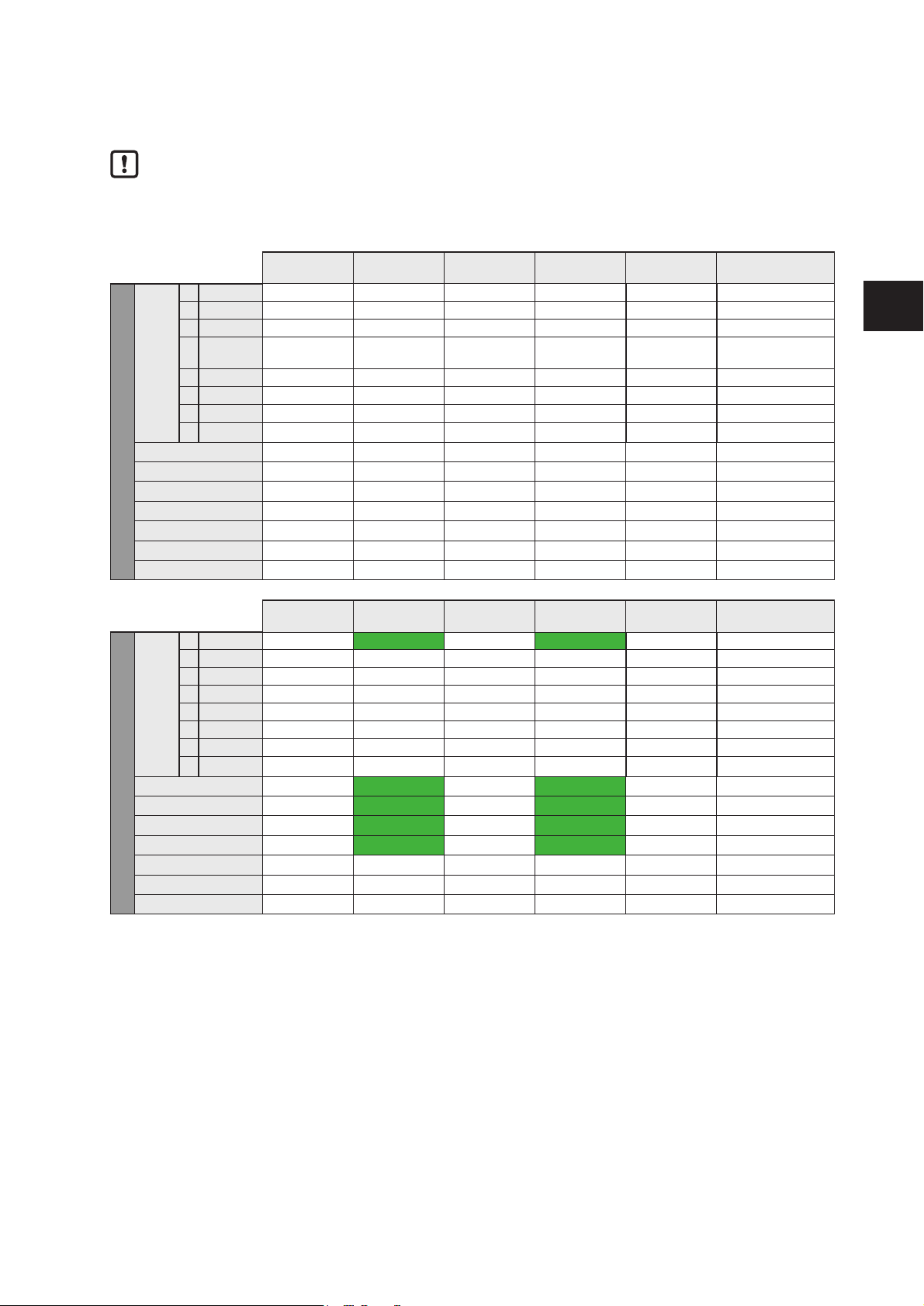
57
UK
13.2 Receive UID automatically (asynchronous mode)
The parameter "Read of UID edge controlled" must be set to 0x00 in the channel configuration.
13.2.1 Command sequence view
Step 0:
no tag in field
Step 1:
tag in field
Step 2:
tag still in field
Step 3:
no tag in field
Step 4:
no tag in field
Remark
PLC process data output
Byte 1
0 0 0 0 0 0 0
1 AO 0 0 0 0 0
2 WR 0 0 0 0 0
3 RD 0 0 0 0 0 No need for RD
setting
4 UR 0 0 0 0 0
5 ER 0 0 0 0 0
6 DR 0 0 0 0 0
7 0 0 0 0 0 0
Byte 2 0x00 0x00 0x00 0x00 0x00
Byte 3 0x00 0x00 0x00 0x00 0x00
Byte 4 0x00 0x00 0x00 0x00 0x00
Byte 5 0x00 0x00 0x00 0x00 0x00
... … … … … …
Byte 19 0x00 0x00 0x00 0x00 0x00
Byte 20 0x00 0x00 0x00 0x00 0x00
Step 0:
no tag in field
Step 1:
tag in field
Step 2:
tag still in field
Step 3:
no tag in field
Step 4:
no tag in field
Remark
PLC process data input
Byte 1
0 TP 0 1 (1) 0 1 (1) 0
1 AI 0 0 0 0 0
2 WR-RDY 0 0 0 0 0
3 RD-RDY 0 0 0 0 0
4 UD 0 0 0 0 0
5 EF 0 0 0 0 0
6 DR-RDY 0 0 0 0 0
7 Diag 0 0 0 0 0
Byte 2 (UID length) 0x00 0x08 0x00 0x08 0x00
Byte 3 (UID data) 0x00 0xE0 (2) 0x00 0xE0 0x00
Byte 4 (UID data) 0x00 0x04 0x00 0x03 0x00
Byte 5 (UID data) 0x00 0x01 0x00 0x0C 0x00
… … … … … …
Byte 19 0x00 0x00 0x00 0x00 0x00
Byte 20 0x00 0x00 0x00 0x00 0x00
(1) TP bit indicate that the RFID tag is detected by the Read/write head.
(2) UID data, the length is dependent from the RFID tag (125kHz = 4 Byte; 13,56 MHz = 8 Byte).
Page 58

58
13.2.2 Payload trafc view
Command request send by controller:
00000000000000000000000000000000000000000000000000000000000000000000000000000000
00000000000000000000000000000000000000000000000000000000000000000000000000000000
Controller: “Receive UID of RFID tag automatically” on channel IO-1 and IO-2
Response send by evaluation unit when command has been processed and a RFID tag is detected on
IO-1 and IO-2:
0108e00401004c5f494c000000000000000000000108e00801138ca1d7cb00000000000000000000
00000000000000000000000000000000000000000000000000000000000000000000000000000000
Evaluation unit: Send “Tag is in field” and UID data with length of 8 bytes from channel IO-1 and IO-2.
Page 59
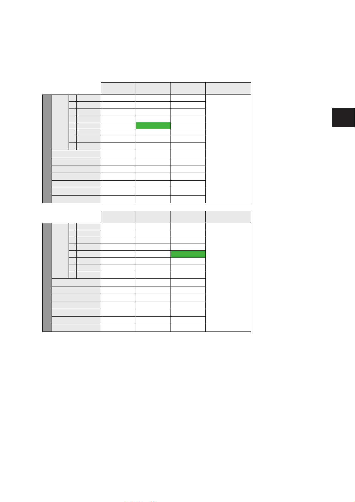
59
UK
13.3 Access to the User data of the RFID tag
To access the User data of the RFID tag, the IO channel has to be set into “user” mode. This can be done
by setting the UR bit of the control byte to 1. In the following command sequence the RFID tag is in the
reading field of the Read/write head.
Step 0:
Tag in field
Step 1:
Activate bit UR
Step 2:
Wait for bit UD
Remark
PLC process data output
Byte 1
0 0 0 0 0 Now the Read/write
head is able to
proceed read and
write requests to
the User data of the
RFID tag.
1 AO 0 0 0
2 WR 0 0 0
3 RD 0 0 0
4 UR 0 1 1
5 0 0 0 0
6 DR 0 0 0
7 0 0 0 0
Byte 2 0x00 0x00 0x00
Byte 3 0x00 0x00 0x00
Byte 4 0x00 0x00 0x00
Byte 5 0x00 0x00 0x00
... … … …
Byte 19 0x00 0x00 0x00
Byte 20 0x00 0x00 0x00
Step 0:
Tag in field
Step 1:
Activate bit UR
Step 2:
Wait for bit UD
Remark
PLC process data input
Byte 1
0 TP 1 1 1 Now the Read/write
head is able to
proceed read and
write requests to
the User data of the
RFID tag.
1 AI 0 0 0
2 WR-RDY 0 0 0
3 RD-RDY 0 0 0
4 UD 0 0 1
5 EF 0 0 0
6 DR-RDY 0 0 0
7 Diag 0 0 0
Byte 2 0x08 0x08 0x00
Byte 3 0xE0 0xE0 0x00
Byte 4 0x04 0x04 0x00
Byte 5 0x04 0x04 0x00
… … … …
Byte 19 0x00 0x00 0x00
Byte 20 0x00 0x00 0x00
Page 60
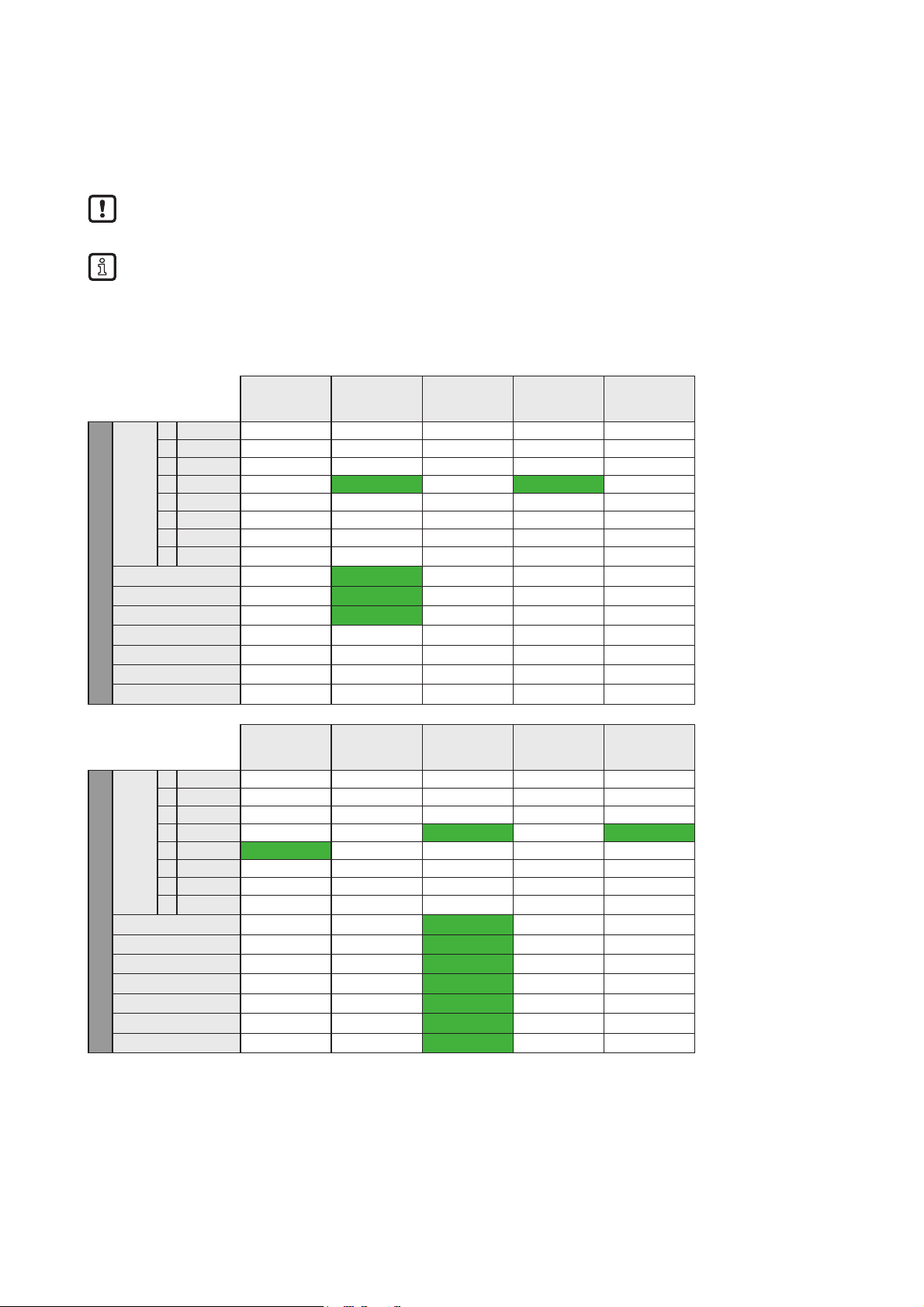
60
13.4 Read User data of the RFID tag on request (synchronous mode)
With one command cycle up to 16 bytes can be read. To read more data, the command cycle has to be
repeated with adapted address setting.
The control and status byte must have value “10” (UD activated) before the following command
sequence can be started.
With one reading cycle (step 4 to 7) up to 16 bytes can be read. If more data shall be read
● the steps 4 to 7 have to be repeated and
● the address offset has to be counted up.
13.4.1 Command sequence view
Step 1:
Bit UD is true
Step 2:
Start reading
(1)
Step 3:
Wait for bit
RD-RDY (2)
Step 4:
Reset bit RD
Step 5:
Wait for reset
bit RD-RDY
PLC process data output
Byte 1
0 0 0 0 0 0 0
1 AO 0 0 0 0 0
2 WR 0 0 0 0 0
3 RD 0 1 1 0 0
4 UR 1 1 1 1 1
5 0 0 0 0 0 0
6 DR 0 0 0 0 0
7 0 0 0 0 0 0
Byte 2 (data length) 0x00 0x08 0x08 0x00 0x00
Byte 3 (address MSB) 0x00 0x00 0x00 0x00 0x00
Byte 4 (address LSB) 0x00 0x10 0x10 0x00 0x00
Byte 5 0x00 0x00 0x00 0x00 0x00
… … … … … …
Byte 19 0x00 0x00 0x00 0x00 0x00
Byte 20 0x00 0x00 0x00 0x00 0x00
Step 1:
Bit UD is true
Step 2:
Start reading
(1)
Step 3:
Wait for bit
RD-RDY (2)
Step 4:
Reset bit RD
Step 5:
Wait for reset
bit RD-RDY
PLC process data input
Byte 1
0 TP 1 1 1 1 1
1 AI 0 0 0 0 0
2 WR-RDY 0 0 0 0 0
3 RD-RDY 0 0 1 1 0
4 UD 1 1 1 1 1
5 EF 0 0 0 0 0
6 DR-RDY 0 0 0 0 0
7 Diag 0 0 0 0 0
Byte 2 (data length) 0x00 0x00 0x08 0x12 0x00
Byte 3 (data) 0x00 0x00 0x12 0x34 0x00
Byte 4 0x00 0x00 0x34 0x56 0x00
Byte 5 0x00 0x00 0x56 0x56 0x00
… … … … … …
Byte 19 0x00 0x00 0x00 0x00 0x00
Byte 20 0x00 0x00 0x00 0x00 0x00
(1) Data length and the memory address of the RFID tag has to be set.
(2) The reading data can be read out from byte 3, the length is dependent from the reading length.
Page 61

61
UK
13.4.2 Payload trafc view
Command request send by controller:
180A0002000000000000000000000000000000001810001000000000000000000000000000000000
00000000000000000000000000000000000000000000000000000000000000000000000000000000
Controller: Read 10 bytes from channel IO-1 at address 0x0002 and 16 bytes at address 0x0010 from
channel IO-2.
Response send by evaluation unit when command has been processed:
190A112233445566778899AA00000000000000001100000000000000000000000000000000000000
00000000000000000000000000000000000000000000000000000000000000000000000000000000
Evaluation unit: Send read User data of channel IO-1, channel IO-2 is not ready with response.
...
190A112233445566778899AA000000000000000019101112131415161718191A1B1C1D1E1F000000
00000000000000000000000000000000000000000000000000000000000000000000000000000000
Evaluation unit: Send “Tag is in field” and User data with length of 16 bytes from channel IO-1 and IO.
Page 62

62
13.5 Write User data to the RFID tag (synchronous mode)
With one command cycle up to 16 bytes can be written. To write more data, the command cycle has to be
repeated with adapted address setting.
The control and status byte must have value “10” before the following command sequence can be
started.
With one write cycle (step 2 to 5) up to 16 bytes can be written. If more data shall be written
● the steps 2 to 5 have to be repeated,
● the address offset has to be counted up and
● the data to be written actualized.
13.5.1 Command sequence view
Step 1:
Bit UD is true
Step 2:
Start writing
(1)
Step 3:
Wait for bit
WR-RDY
Step 4:
Reset bit RD
Step 5:
Wait for reset
bit WR-RDY
PLC process data output
Byte 1
0 0 0 0 0 0 0
1 AO 0 0 0 0 0
2 WR 0 1 1 0 0
3 RD 0 0 0 0 0
4 UR 1 1 1 1 1
5 0 0 0 0 0 0
6 DR 0 0 0 0 0
7 0 0 0 0 0 0
Byte 2 (data length) 0x00 0x08 0x00 0x00 0x00
Byte 3 (address MSB) 0x00 0x00 0x00 0x00 0x00
Byte 4 (address LSB) 0x00 0x10 0x00 0x00 0x00
… … … … … …
Byte 19 0x00 0x00 0x00 0x00 0x00
Byte 20 0x00 0x00 0x00 0x00 0x00
Step 1:
Bit UD is true
Step 2:
Start writing
(1)
Step 3:
Wait for bit
WR-RDY
Step 4:
Reset bit RD
Step 5:
Wait for reset
bit WR-RDY
PLC process data input
Byte 1
0 TP 1 1 1 1 1
1 AI 0 0 0 0 0
2 WR-RDY 0 0 1 1 0
3 RD-RDY 0 0 0 1 0
4 UD 1 1 1 1 1
5 EF 0 0 0 0 0
6 DR-RDY 0 0 0 0 0
7 Diag 0 0 0 0 0
Byte 2 0x00 0x00 0x00 0x12 0x00
Byte 3 0x00 0x00 0x00 0x34 0x00
Byte 4 0x00 0x00 0x00 0x56 0x00
… … … … … …
Byte 19 0x00 0x00 0x00 0x00 0x00
Byte 20 0x00 0x00 0x00 0x00 0x00
(1) Data length and the memory address of the RFID tag has to be set.
Page 63

63
UK
13.5.2 Payload trafc view
Command request send by controller:
14040008C1C2C3C4000000000000000000000000140A0020B1B2B3B4B5B6B7B8B9BA000000000000
00000000000000000000000000000000000000000000000000000000000000000000000000000000
Controller: Write 4 bytes at address 0x0008 to User data of RFID tag at channel IO-1 and 10 bytes at
address 0x0020 to tag at channel IO-2.
Response send by evaluation unit when command has been processed:
1100000000000000000000000000000000000000150A000000000000000000000000000000000000
00000000000000000000000000000000000000000000000000000000000000000000000000000000
Evaluation unit: Data write on channel IO-1 not ready, data write on channel IO-2 ready and confirmed
with data length written = 10 bytes.
...
1504000000000000000000000000000000000000150A000000000000000000000000000000000000
00000000000000000000000000000000000000000000000000000000000000000000000000000000
Evaluation unit: Data write on channel IO-1 ready and confirmed with data length written = 4 bytes, data
write on channel IO-2 ready and confirmed with data length written = 10 bytes.
Page 64
64
13.6 Write verified to user memory to the RFID tag (synchronous mode)
The control and status byte must have bit UR and UD set to 1 before the following command
sequence can be started.
13.6.1 Command sequence view
Step 0:
no tag in field
Step 1:
tag in field
Step 2:
tag still in field
Step 3: tag left
the field
Step 4: tag left
the field
Remark
PLC process data output
Byte 1
0 0 0 0 0 0 0
1 AO 0 0 0 0 0
2 WR 0 0 1 1 0 Set WR and RD
to 1 when TP=1 is
detected
3 RD 0 0 1 1 0
4 UR 1 1 1 1 1 Set UR to 1
5 ER 0 0 0 0 0
6 DR 0 0 0 0 0
7 0 0 0 0 0 0
Byte 2 (Data length) 0x00 0x00 0x10 0x10 0x00 Number of User
data bytes to write
Byte 3 (Address-H) 0x00 0x00 0x00 0x00 0x00 Address (H-Byte)
Byte 4 (Address-L) 0x00 0x00 0x02 0x02 0x00 Address (L-Byte)
Byte 5 0x00 0x00 0xAA 0xAA 0x00 User data byte 1
Byte 6 0x00 0x00 0xBB 0xBB 0x00 User data byte 2
.. … … … … … …
Byte 20 0x00 0x00 0x00 0x00 0x00
Step 0:
no tag in field
Step 1:
tag in field
Step 2:
tag still in field
Step 3: tag left
the field
Step 4: tag left
the field
Remark
PLC process data input
Byte 1
0 TP 0 1 (1) 1 0 0
1 AI 0 0 0 0 0
2 WR-RDY 0 0 1 1 0
3 RD-RDY 0 0 1 1 0
4 UD 1 1 1 1 1
5 EF 0 0 0 0 0
6 DR-RDY 0 0 0 0 0
7 Diag 0 0 0 0 0
Byte 2 (Data length) 0x00 0x00 0x10 (2) 0x10 0x00 Number of bytes
read from the RFID
tag
Byte 3 (User data) 0x00 0x00 0xAA 0xAA 0x00 User data byte 1
read
Byte 4 (User data) 0x00 0x00 0xBB 0xBB 0x00 User data byte 2
read
… … … … … … …
Byte 19 0x00 0x00 0x00 0x00 0x00
Byte 20 0x00 0x00 0x00 0x00 0x00
(1) TP bit indicate that the RFID tag is detected by the Read/write head.
(2) Number of User data bytes read from the RFID tag.
Page 65

65
UK
13.6.2 Payload trafc view
Command request send by controller:
1C040008A1A2A3A40000000000000000000000001C0C0020E1E2E3E4E5E6E7E8E9EAEBEC00000000
00000000000000000000000000000000000000000000000000000000000000000000000000000000
Controller: Write 4 bytes at address 0x0008 to User data of RFID tag at channel IO-1 and 12 bytes at
address 0x0020 to tag at channel IO-2.
Response send by evaluation unit when command has been processed:
1D04A1A2A3A400000000000000000000000000001100000000000000000000000000000000000000
00000000000000000000000000000000000000000000000000000000000000000000000000000000
Evaluation unit: Data write and read back from tag ready at channel IO-1 ready, data write on channel IO2 not ready.
...
1D04A1A2A3A400000000000000000000000000001D0CE1E2E3E4E5E6E7E8E9EAEBEC000000000000
00000000000000000000000000000000000000000000000000000000000000000000000000000000
Evaluation unit: Data write and read back from tag ready at channel IO-1 read, data write and read back
from tag ready at channel IO-2.
Page 66

66
13.7 Read User data of the RFID tag automatically (asynchronous mode)
The control and status byte must have value “10” before the following command sequence can be
started.
13.7.1 Command sequence view
Step 0:
no tag in field
Step 1:
no tag in field
Step 2:
tag in field
Step 3:
no tag in field
Step 4:
tag in field
Remark
PLC process data output
Byte 1
0 0 0 0 0 0 0
1 AO 0 0 0 0 0
2 WR 0 0 0 0 0
3 RD 0 1 1 1 1 Set ER and RD
synchronously to 1
4 UR 1 1 1 1 1 Set UR to 1
5 ER 0 1 1 1 1
6 DR 0 0 0 0 0
7 0 0 0 0 0 0
Byte 2 (Data length) 0x00 0x10 0x10 0x10 0x10 Number of User
data bytes to read
Byte 3 (Address-H) 0x00 0x00 0x00 0x00 0x00 Address (H-Byte)
Byte 4 (Address-L) 0x00 0x02 0x02 0x02 0x02 Address (L-Byte)
Byte 5 0x00 0x00 0x00 0x00 0x00
… … … … … …
Byte 19 0x00 0x00 0x00 0x00 0x00
Byte 20 0x00 0x00 0x00 0x00 0x00
Step 0:
no tag in field
Step 1:
no tag in field
Step 2:
tag in field
Step 3:
no tag in field
Step 4:
tag in field
Remark
PLC process data input
Byte 1
0 TP 0 0 1 (1) 0 1
1 AI 0 0 0 0 0
2 WR-RDY 0 0 0 0 0
3 RD-RDY 0 1 1 1 1
4 UD 1 1 1 1 1
5 EF 0 1 1 1 1
6 DR-RDY 0 0 0 0 0
7 Diag 0 0 0 0 0
Byte 2 (Data length) 0x00 0x00 0x10 (2) 0x00 0x10 (2) Number of bytes
read
Byte 3 (User data) 0x00 0x00 0x11 0x00 0xAA User data byte 1
Byte 4 (User data) 0x00 0x00 0x22 0x00 0xBB User data byte 2
Byte 5 (User data) 0x00 0x00 0x33 0x00 0xCC User data byte 3
… … … … … … …
Byte 19 0x00 0x00 0x00 0x00 0x00
Byte 20 0x00 0x00 0x00 0x00 0x00
(1) TP bit indicate that the RFID tag is detected by the Read/write head.
(2) User data length of the RFID tag.
Page 67

67
UK
13.7.2 Payload trafc view
Command request send by controller:
3808000400000000000000000000000000000000380C000800000000000000000000000000000000
00000000000000000000000000000000000000000000000000000000000000000000000000000000
Controller: Read 8 bytes from channel IO-1 at address 0x0004 and 12 bytes at address 0x0008 from
channel IO-2 automatically.
Response send by evaluation unit when command has been processed:
38000000000000000000000000000000000000003800000000000000000000000000000000000000
00000000000000000000000000000000000000000000000000000000000000000000000000000000
Evaluation unit: Send read User data of channel IO-1 and IO-2. Because no tag is present the read data
length are set to 0x00.
After the command request is received, the evaluation unit always send one response to confirm
the new mode.
...
3908A1A2A3A4A5A6A7A8000000000000000000003800000000000000000000000000000000000000
00000000000000000000000000000000000000000000000000000000000000000000000000000000
Evaluation unit: Send data of channel IO-1, because tag is now present and could be read.
...
38000000000000000000000000000000000000003800000000000000000000000000000000000000
00000000000000000000000000000000000000000000000000000000000000000000000000000000
Evaluation unit: Send data of channel IO-1, because tag is no more present.
...
3800000000000000000000000000000000000000390CB1B2B3B4B5B6B7B8B9BABBBC000000000000
00000000000000000000000000000000000000000000000000000000000000000000000000000000
Evaluation unit: Send data of channel IO-2, because tag is now present and could be read
The automatically read mode is terminated when the bit "ER" is reset in the control byte of the
command request.
Page 68
68
13.8 Read diagnostics information
Dependent on the previously executed command, the diagnostic request must be prepared.
The control and status byte must have value "00" before the following command sequence can be
started.
13.8.1 Command sequence view, read diagnostics in mode “Read UID”
Step 0:
diagnostics
event
Step 1:
set bit DR
Step 5:
wait for bit DRRDY
Step 6:
reset bit DR
Step 7:
wait for reset
bit DR-RDY
PLC process data output
Byte 1
0 0 0 0 0 0 0
1 AO 0 0 0 0 0
2 WR 0 0 0 0 0
3 RD 0 0 0 0 0
4 UR 0 0 0 0 0
5 0 0 0 0 0 0
6 DR 0 1 1 0 0
7 0 0 0 0 0 0
Byte 2 (data length) 0x00 0x00 0x00 0x00 0x00
Byte 3 (address MSB) 0x00 0x00 0x00 0x00 0x00
Byte 4 (address LSB) 0x00 0x00 0x00 0x00 0x00
… … … … … …
Byte 19 0x00 0x00 0x00 0x00 0x00
Byte 20 0x00 0x00 0x00 0x00 0x00
Step 0:
diagnostics
event
Step 1:
set bit DR
Step 5:
wait for bit DRRDY
Step 6:
reset bit DR
Step 7:
wait for reset
bit DR-RDY
PLC process data input
Byte 1
0 TP 0 0 0 0 0
1 AI 0 0 0 0 0
2 WR-RDY 0 0 0 0 0
3 RD-RDY 0 0 0 0 0
4 UD 0 0 0 0 0
5 EF 0 0 0 0 0
6 DR-RDY 0 0 1 1 0
7 Diag 1 0 0 0 0
Byte 2 0x00 0x00 0x02 0x00 0x00
Byte 3 0x00 0x00 0xF1 0x00 0x00
Byte 4 0x00 0x00 0xFE 0x00 0x00
… … … … … …
Byte 19 0x00 0x00 0x00 0x00 0x00
Byte 20 0x00 0x00 0x00 0x00 0x00
Page 69

69
UK
13.8.2 Payload trafc view, read diagnostics in mode “Read UID”
Command request send by controller:
40000000000000000000000000000000000000004000000000000000000000000000000000000000
00000000000000000000000000000000000000000000000000000000000000000000000000000000
Controller: Read diagnostics information from channel IO-1 and IO-2.
Response send by evaluation unit when command has been processed:
4001F1FE020000000000000000000000000000004000000000000000000000000000000000000000
00000000000000000000000000000000000000000000000000000000000000000000000000000000
Evaluation unit: Channel IO-1 had diagnostics information with 1 element. Diagnostics "Presence error,
tag has left transmission window". Channel IO-1 has no diagnostics information.
Before a new diagnostics information can be read out, the DR bit within the Control byte must be
reset.
Example how to reset the DR bit on both channels:
00000000000000000000000000000000000000000000000000000000000000000000000000000000
00000000000000000000000000000000000000000000000000000000000000000000000000000000
Controller: Remove diagnostics read request on channel IO-1 and IO-2.
Page 70
70
13.8.3 Command sequence view, read diagnostics in mode “Read/write User data of the RFID tag”
Step 0:
tag in field
Step 1:
diagnostics
event
Step 2:
prepare diag.
read
Step 3:
start diag.
read
Step 4:
end diag. read
Remark
PLC process data output
Byte 1
0 0 0 0 0 0 0
1 AO 0 0 0 0 0
2 WR 0 0 0 0 0
3 RD 0 1 0 0 0 Set RD=0 to read
diagnostics
4 UR 1 1 1 1 1 Keep UR=1
5 ER 0 0 0 0 0
6 DR 0 0 0 1 0 Set DR to 1 to
read diagnostics
7 0 0 0 0 0 0
Byte 2 0x00 0x00 0x00 0x00 0x00
Byte 3 0x00 0x00 0x00 0x00 0x00
Byte 4 0x00 0x00 0x00 0x00 0x00
Byte 5 0x00 0x00 0x00 0x00 0x00
… … … … … …
Byte 19 0x00 0x00 0x00 0x00 0x00
Byte 20 0x00 0x00 0x00 0x00 0x00
Step 0:
tag in field
Step 1:
diagnostics
event
Step 2:
prepare diag.
read
Step 3:
start diag.
read
Step 4:
end diag. read
Remark
PLC process data input
Byte 1
0 TP 1 (1) 1 1 1 1
1 AI 0 0 0 0 0
2 WR-RDY 0 0 0 0 0
3 RD-RDY 0 1 0 0 0
4 UD 1 1 1 1 1
5 EF 0 0 0 0 0
6 DR-RDY 0 0 0 1 0
7 Diag 0 1 (2) 1 0 0
Byte 2 (Diag length) 0x00 0x00 0x00 0x01 (3) 0x00
Byte 3 (Diag data) 0x00 0x00 0x00 0xF1 0x00
Byte 4 (Diag data) 0x00 0x00 0x00 0xFE 0x00
Byte 5 (Diag data) 0x00 0x00 0x00 0x02 0x00
Byte 6 (Diag data) 0x00 0x00 0x00 0x00 0x00
… … … … … …
Byte 20 0x00 0x00 0x00 0x00 0x00
(1) TP=1 indicate that the RFID tag is detected by the Read/write head.
(2) Diagnostic detected by the evaluation unit.
(3) Number of error codes.
Page 71

71
UK
13.8.4 Payload trafc view, read diagnostics in mode “Read/write User data of the RFID
tag”
Command request send by controller:
50000000000000000000000000000000000000005000000000000000000000000000000000000000
00000000000000000000000000000000000000000000000000000000000000000000000000000000
Controller: Read diagnostics information from channel IO-1 and IO-2.
Response send by evaluation unit when command has been processed:
5001F1FE020000000000000000000000000000005000000000000000000000000000000000000000
00000000000000000000000000000000000000000000000000000000000000000000000000000000
Evaluation unit: Channel IO-1 had diagnostics information with 1 element. Diagnostics "Presence error,
tag has left transmission window". Channel IO-1 has no diagnostics information.
Before a new diagnostics information can be read out, the DR bit within the Control byte must be
reset.
Example how to reset the DR bit on both channels:
10000000000000000000000000000000000000001000000000000000000000000000000000000000
00000000000000000000000000000000000000000000000000000000000000000000000000000000
Controller: Remove diagnostics read request on channel IO-1 and IO-2.
Page 72
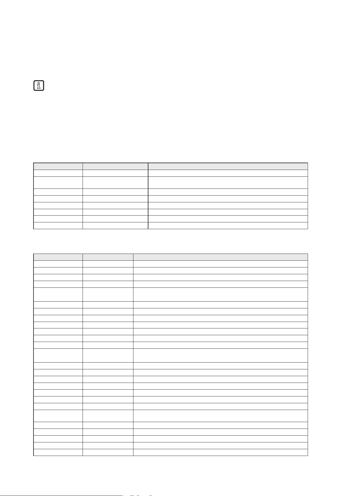
72
14 Error codes of the evaluation unit
Error codes are signaled with bit “Diag” within the status byte of the response data of the evaluation unit.
If more diagnostic events are available, the channel can transfer up to 4 diagnostics simultaneously. The
hardware diagnostic events, which are device relevant, are indicated by the Diag bit on all channels.
Inactive channels can only transfer hardware diagnostic events.
Example:
Command response of the evaluation unit for command “DR”
C001F4FE9000
14.1 Error group RFID tag (F1FE)
Error group F1 Error code Description
Tag/transponder F1FE0200 Tag not present, tag has left the transmission window
Tag/transponder F1FE0300 Address or command does not match the RFID tag characteristics,
memory size invalid
Tag/transponder F1FE0400 Tag is defective, replace tag or battery
Tag/transponder F1FE0500 Overflow of the RFID tag memory UID > 16 bytes
Tag/transponder F1FE0900 Command not supported by the RFID tag
Tag/transponder F1FE0A00 Access error, e.g. block locked. See ISO18000-x
Tag/transponder F1FE0B00 General tag error which is not specified in detail
Tag/transponder F1FE0C00 Unknown internal error
14.2 Error group evaluation unit (F4FE)
Error group F4 Error code Description
Evaluation unit F4FE0100 Power supply failure
Evaluation unit F4FE0200 Hardware failure, short circuit and overload
Evaluation unit F4FE0201 Allowed temperature exceeded
Evaluation unit F4FE0300 read/write head does not function because time out occurred
Evaluation unit F4FE0400 Command buffer overflow of the IO server queue
(Internal error)
Evaluation unit F4FE0500 Data buffer overflow, memory allocation (internal error)
Evaluation unit F4FE0600 Command is not supported in this mode (internal error)
Evaluation unit F4FE8100 ID-Link Master inactive. i.e. after power on (internal error)
Evaluation unit F4FE8200 Internal IO port server error (internal error)
Evaluation unit F4FE8300 Invalid IO port parameter, e.g. channel (internal error)
Evaluation unit F4FE8400 Vendor-specific error with the command PUT
Evaluation unit F4FE8500 IO port server resets channel
Evaluation unit F4FE8600 Data not available for delayed C/Q inputs or delayed UID
(Internal fault)
Evaluation unit F4FE8700 Reconfiguration of the IO port channel not yet allowed (internal error )
Evaluation unit F4FE8800 Parameter flag of the IO port not set (internal error )
Evaluation unit F4FE8900 General error detected by ID-Link master
Evaluation unit F4FE8A00 CRC error detected by ID-Link Master
Evaluation unit F4FE8B00 Object not found detected by ID-Link Master
Evaluation unit F4FE8C00 Data read/write area in the command not valid
Evaluation unit F4FE8D00 IO port channel reconfigured
Evaluation unit F4FE8E00 The read/write head could not process the command, i.e. read/write length
exceeded, tag memory error, write to locked block
Evaluation unit F4FE8F00 Tag data length exceeded (block size * block number)
Evaluation unit F4FE9001 Short circuit at output driver detected (C/Qo)
Evaluation unit F4FE9002 Undervoltage at output driver detected (AUX or L+)
Evaluation unit F4FE9003 Overload at output driver detected (L+ or C/Qo)
Evaluation unit F4FE9004 Over temperature at output driver detected
Page 73

73
UK
Evaluation unit F4FE9005 Wire break on the read/write head
Evaluation unit F4FE9006 Upper limit reached at output driver.
Evaluation unit F4FE9007 Undervoltage at C/Qo detected
Evaluation unit F4FE9008 General read/write head error detected
Evaluation unit F4FE9009 read/write head communication error
Evaluation unit F4FE900A I²C communication error (internal error)
Evaluation unit F4FE900B I²C communication parity error (internal error)
Evaluation unit F4FE9401 Frontend error detected by the read/write head
Evaluation unit F4FE9402 General error detected by the read/write head
Evaluation unit F4FE9403 ID-Link error detected by the read/write head
Evaluation unit F4FE9404 Buffer overrun (overflow???) error detected by the read/write head
Evaluation unit F4FEA000 Invalid command code detected
Evaluation unit F4FEA001 Invalid command parameter detected
Evaluation unit F4FEA002 Invalid command data detected
Evaluation unit F4FEA003 Invalid ticket number or ticket length detected
Evaluation unit F4FEA100 Configuration of the evaluation unit failed (CR1 / CR2 )
Evaluation unit F4FEA200 Configuration of the IO channel failed (internal error)
Evaluation unit F4FEA300 Reading of C/Qi / IQ inputs (internal error)
Evaluation unit F4FEA400 Write to output C/Qo failed (internal error)
Evaluation unit F4FEA500 High current setting failed (internal error)
Evaluation unit F4FEA600 Reading of UID failed (internal error)
Evaluation unit F4FEA700 Reading of the user data memory of the RFID tag failed (internal error)
Evaluation unit F4FEA800 Writing to the user data memory of the RFID tag failed, command WU (internal
error)
Evaluation unit F4FEA900 Writing to the user data memory of the RFID tag failed, command WV (internal
error)
Evaluation unit F4FEAA00 Verification of the user data memory of the RFID tag failed, command "WV"
(internal error)
Evaluation unit F4FEAB00 Setting of the antenna field on/off failed, command "AN"
Evaluation unit F4FEAC00 ID-Link master could not read the RFID tag blocks (internal error)
14.3 Error group Communication User – evaluation unit (F5FE )
Error group F5 Error code Description
Communication user
- evaluation unit
F5FE0800 Command is processed by another user
(indicated by the evaluation unit)
Communication user
- evaluation unit
F5FE8000 More than one command requested by user (DR, WR, Diag)
Communication user
- evaluation unit
F5FE8100 It is attempted to abort the command for synchronous reading or writing
Communication user
- evaluation unit
F5FE8300 Command parameter for asynchronous reading invalid
Page 74

74
15 List of abbreviations
Definition Remark
ACD
Address Conflict Detection. Procedure to detect IPv4 address conflicts as well as duplicate
addresses. See RFC 5227.
Antenna RFID antenna built in a read/write head
Assembly Instance
Assembly instances are instances of an I/O data block with predefined functionality which can
be exchanged between several communication participants. It is known to the communication
participants which data at which length is to be exchanged.
Block size Size of one block of the RFID tag, e.g. 4/8/32 bytes
CIP
Common Industrial Protocol. Object-oriented description of a communication protocol for
industrial requirements which is currently used by four different field buses (CompoNet,
DeviceNet, ControlNet and EtherNet/IP).
Connection Describes the logical connection between two application objects.
Controller PLC e.g. Allen Bradley Compact Logix
DLR
Device Level Ring protocol. Supports the media redundance in a ring structure Ethernet
environment.
EDS Electronic Data Sheet ist a device description file.
Emergency system Web server with reduced functionality to download the firmware of the evaluation unit
evaluation unit RFID Identification unit DTE103
Explicit Messaging Acyclic data exchange between I/O scanner and I/O adapter based on TCP/IP communication.
Hexadecimal Numeral format, which use 16 values to represent a numeric value: 0..9, A, B, C, D, E, F
I/O Adapter Comparable to a slave system (Target in EIP)
I/O Messaging oder Implicit
Messaging
Cyclic data exchange between I/O scanner and I/O adapter based on UDP/IP communication.
I/O Scanner Comparable to a master system (Originator in EIP)
Tag, transponder RFID RFID tag, e.g. E80360, E80370
ODVA Open Device Net Vendor Association
PC Personal computer, e.g. desktop computer, notebook
PermData
Nonvolatile data area of the evaluation unit for storage of user specific settings, like fieldbus
parameter, address settings and so on.
PLC Programmable Logic Controller, e.g. Allen Bradley Compact Logix
Process data input image Data area where the PLC can read the outputs of the external periphery devices. ( %IBx )
Process data output image Data area where the PLC can write to the inputs of the external periphery devices. ( %QBx )
read/write head RFID read/write head, e.g. ANT411, ANT513
User data Data area of the RFID tag which can be read and written randomly
Web client PC program to send “http protocol” requests, e.g. Firefox, Internet Explorer
Web server Built in “http protocol” server to service request from a PC
 Loading...