

Page 1

OPERATING AND MAINTENANCE
INSTRUCTIONS
HIGH POWER TWT AMPLIFIER
Ametek CTS US
Instruments for Industry
903 South Second Street
Ronkonkoma, NY 11779
Phone 631 467-8400
Fax 631 467-8558
Email :
MODEL T188-250
DOCUMENT NUMBER
T188-250MN.V1.0
Page 2

TABLE OF CONTENTS
SECTION DESCRIPTION PAGE
1.0 INTRODUCTION ............................................................................................................................... 3
2.0 GENERAL DESCRIPTION ................................................................................................................ 4
3.0 WARRANTY INFORMATION ........................................................................................................ 10
4.0 GENERAL INFORMATION
4.1 Scope Of This Manual ......................................................................................................... 11
4.2 Operation Overview ............................................................................................................. 11
4.3 General Specifications ......................................................................................................... 12
4.4 Functional Description ......................................................................................................... 12
4.5 Protection Circuits ............................................................................................................... 13
4.6 Status Indicators, Controls and Connectors ......................................................................... 13
4.7 TWT Operating Instructions ................................................................................................ 15
4.8 Data Sheets ................................................................................................................. 18
5.0 PRINCIPLES OF OPERATION
5.1 Proper Usage And Warnings ............................................................................................... 17
5.2 Features ................................................................................................................ 17
6.0 IEEE-488 INTERFACE OPTION
6.1 Introduction.......................................................................................................................... 18
6.2 Remote Initialization ............................................................................................................ 18
6.3 GPIB Address ...................................................................................................................... 18
6.4 IEEE-488 Commands .......................................................................................................... 19
6.5 RS-232 ................................................................................................................. 21
7.0 MAINTENANCE AND SERVICING
7.1 Periodic Maintenance .......................................................................................................... 22
7.2 Servicing The Amplifier ...................................................................................................... 22
7.3 Equipment Return Procedure ............................................................................................... 23
LIST OF FIGURES
FIGURE DESCRIPTION PAGE
1.0 TWTA ILLUSTRATION ................................................................................................................... 3
2.0 SYSTEM BLOCK DIAGRAM............................................................................................................ 6
3.0 REAR PANEL ILLUSTRATION ........................................................................................................ 9
4.0 FRONT DISPLAY PANEL START UP MENU ............................................................................... 11
5.0 GPIB ADDRESS MENU ................................................................................................................. 12
6.0 OPERATE MENU ................................................................................................................. 13
7.0 TURNING ON THE AMPLIFIER .................................................................................................... 14
8.0 OPERATE MODE ................................................................................................................. 15
LIST OF APPENDICES
SECTION APPENDIX DESCRIPTION PAGE
8.0 A DATA SHEETS .................................................................................................... 24
9.0 B DRAWINGS.......................................................................................................... 25
Page
2
Page 3
SECTION 1.0
INTRODUCTION
Congratulations on the purchase of your new Wide Band Amplifier from Instruments For Industry,
Inc. Your new Wide Band Amplifier incorporates the finest advancements in the state of the art
electronics technology available in a compact, portable and versatile package. Your Wide Band
Amplifier's quality, performance and trouble free operation depends on you thoroughly reading
through this manual and familiarizing yourself with its proper operation and usage.
Your Wide Band Amplifier comes with the following accessories, be sure to check your packaging
for the items listed below before disposing of the packaging.
CONTENTS
( For a typical Wide Band Amplifier )
Quantity Description
1 TWT High Power Wide Band Amplifier, P/N T188-250
1 Mating AC Power Line cord
1 Operation and Instruction Manual
1 Data Sheets (Included with the unit)
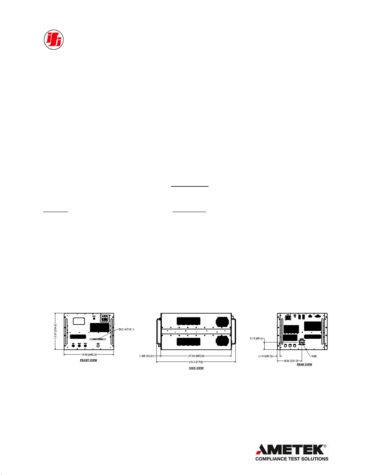
FIGURE 1.0
OUTLINE DRAWING
Page
3
Page 4

SECTION 2.0
GENERAL DESCRIPTION
The Instruments For Industry, Inc. ( IFI ) manufactured TWT Wide Band Amplifier is a Bench Top
or rack mount amplifier providing a nominal output power of at least 250 Watts from 7.0 GHz to
18.0 GHz . The minimum saturated output power midband of the operating frequency range is more
than 250 Watts.
The Amplifier features a Touchscreen Display that displays continuous forward and reflected power
metering. The display also provides the operator with operating status and self diagnostic fault
indications.
The Amplifier incorporates protection circuits that monitor and control so that the amplifier cannot be
damaged by any mismatched load.
The Amplifier has an IEEE-488, RS232 ,USB and Ethernet interface which allows the amplifier to be
remotely controlled through the use of a computer .
To operate the Amplifier, connect a Single phase or three phase power line (50/60 Hz), to the Power
line connector on the rear panel of the unit.
Page
4
Page 5

SECTION 3.0
WARRANTY INFORMATION
Instruments For Industry, Inc. (IFI) warrants each product of its manufacture to be free from any
defect in material and workmanship for a period of three years from shipment to the original
purchaser. All warranty returns, however, must first be authorized by our factory office
representative. Refer to the Service Section for information on how to return items for warranty
repair.
Warranty liability shall be limited to repair or replacement of, or part thereof, which proves to be
defective after inspection by IFI. This warranty shall not apply to any IFI product that has been
disassembled, modified, physically or electrically damaged or any product that has been subjected to
conditions exceeding the applicable specifications or ratings.
IFI shall not be liable for any direct or consequential injury, loss or damage incurred through the use,
or the inability to use, any IFI product.
IFI reserves the right to make design changes to any IFI product without incurring any obligation to
make the same changes to previously purchased units.
This warranty is the full extent of obligation and liability assumed by IFI with respect to any and all
IFI products. IFI neither makes, nor authorizes any person to make, any other guarantee or warranty
concerning IFI Products.
SECTION 4.0
Page
5
Page 6
GENERAL INFORMATION
4.1 SCOPE OF THIS MANUAL
This manual is intended to inform a qualified transmitter operator or technician of the normal
operating and maintenance procedures for the TWT Amplifier. It is not intended to be a course of
instruction for unqualified personnel.
4.2 OPERATION OVERVIEW
The Amplifier is designed to amplify a low level microwave signal and supply a high power CW
output. The Amplifier system function is accomplished primarily through the use of a Traveling
Wave Tube (TWT), control circuitry and power supplies, which can be controlled either locally or
remotely. The major subassemblies are mounted on two separated decks. The upper deck houses the
Collector supply, Filament supply, TWT, control circuitry and all the RF components. The lower
deck houses the Helix supply.
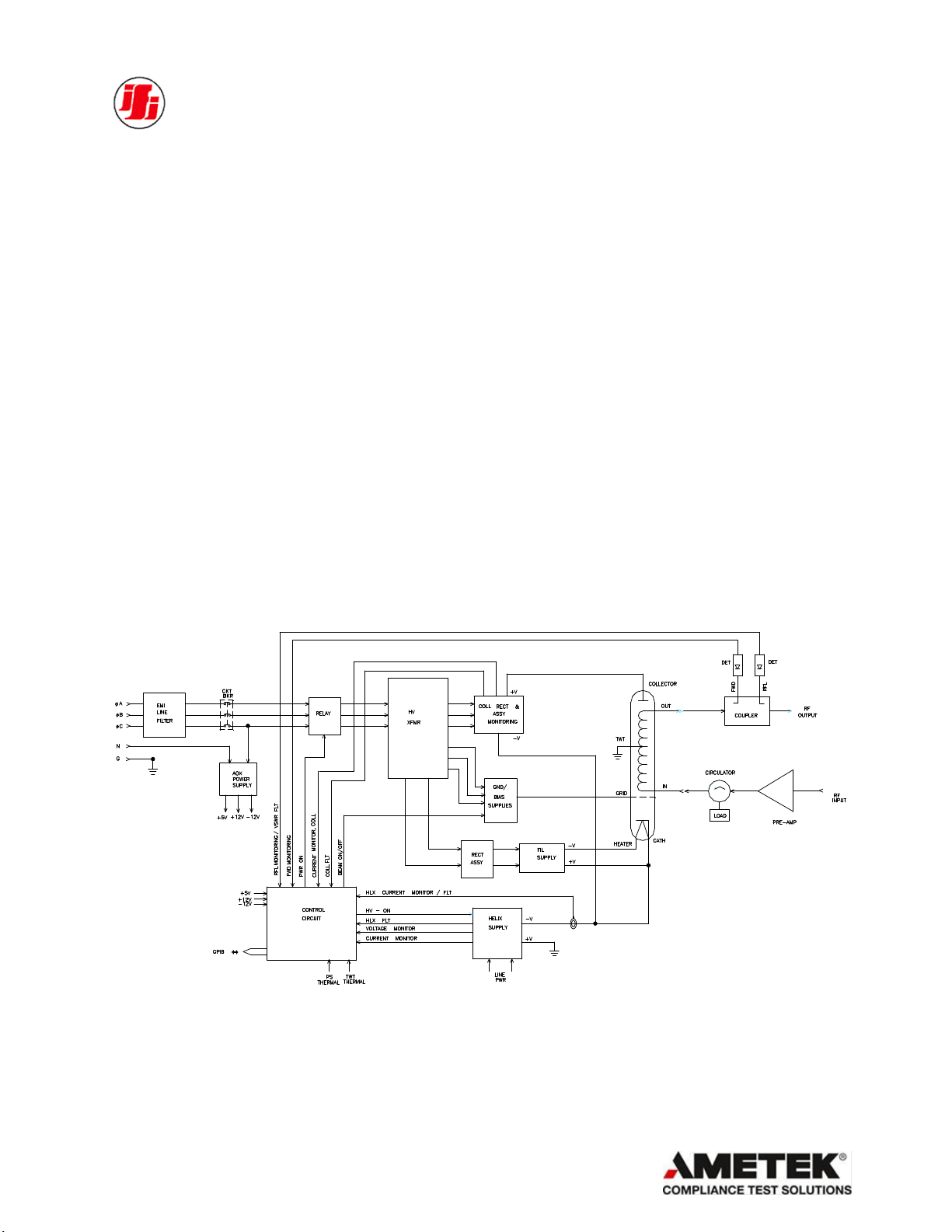
FIGURE 2.0
SYSTEM BLOCK DIAGRAM
4.3 GENERAL SPECIFICATIONS
Page
6
Page 7

The specifications listed below represent the minimum performance characteristics at the
time of delivery.
SPECIFICATIONS
Frequency Response: 7.0 GHz – 18.0 GHz
Power Output: 250 Watts
AC Source: 100-240VAC, 50/60 Hz, Single Phase [refer to label information
provided on the amplifier]
Power Gain: 55 dB
Input Impedance: Nominal 50 Ohms unbalanced
Output Impedance: Nominal 50 Ohms unbalanced
Input Signal Levels: < 0 dBm ( 1.0 mW ) See data sheet for specific input drive levels
Duty Cycle: CW
Spurious: -50dBc
4.4 Functional Description
The required voltages and currents to operate the TWT are provided by the Helix, Collector and
Filament supplies. The Helix supply provides the negative high voltage potential between TWT
Cathode and ground. The Collector supply provides the high voltage potential between the TWT
Cathode and Collector. The Filament supply provides the Heater voltage and floats at high voltage
Cathode potential. In some tubes a Grid element is used to switch the TWT beam ON and OFF.
The primary control circuitry and the service power supplies (+5V, +/- 12V, + 24V) are energized
when the main circuit breaker is turned ON. Upon pressing the AMP ON switch, the Filament and the
Collector supplies are energized and a three minute warm up time is initiated. At the completion of
the three minute time out the Helix supply is enabled and the Amplifier then goes to STBY mode if
no faults were detected. Upon pressing the OPERATE switch the TWT is then turned ON.
Page
7
Page 8

4.5 PROTECTION CIRCUITS
The TWT Amplifier is designed with a variety of protection circuits to provide safeguards for the
amplifier should any adverse electrical conditions occur or if the amplifier accidentally experiences
operator deviation of the design application. Listed below are the safeguards.
4.5.1 Overheat Protection
The TWT, a critical component of this Amplifier, is mounted to a heat sink, which is in turn, air
cooled by high efficiency blower. Should an overheating condition occur, either through component
failure or by a restricted airflow, the Amplifier contains heat sensors that will shut down the system.
As a result, the air inlet and outlet openings should be free of obstructions for proper cooling of the
amplifier. Operation is restored by the Reset button when the amplifier cools to normal temperature
levels.
4.5.2 Power Supply Faults
The Power Supply Fault circuit monitors the Helix and Collector power supplies and produces a fault
indication should any voltage level deviate from normal operating parameters. Each power supply
voltage output is monitored and displayed. Should any power supply voltage deviate from the design
parameters, the Power Supply Fault Indication LED (RED), located on the front panel of the
Amplifier will illuminate and the related fault will be displayed on the LCD display located on the
front panel.
4.5.3 Mismatch Protection
The Amplifier is designed to operate with a tuned 50 Ohm load. Should any mismatching of the 50
Ohm load occur, the Reverse Power, also called Reflective Power, will increase, producing a high
VSWR. The Amplifier microprocessor monitors the Reverse Power levels by utilizing a Dual
Directional Coupler. When the Reflected Power exceeds 25% the Amplifier Output Power The
amplifier will go to STBY and the High VSWR message will be indicated on the LCD display. The
Reverse Power is also displayed on the LCD Display for operator monitoring for any mismatched
load.
4.6 STATUS INDICATORS, CONTROLS AND CONNECTORS
The Amplifier has various controls and status indicators which are identified below and can be
visually located on Figure 1.0, Outline Drawing and Figure 3.0, Rear Panel Illustration. A narrative
description for the function and purpose of each control and status indicator is provided within
paragraphs 4.7.1 and 4.7.2.
Page
8
Page 9
RF AMPLIFIER
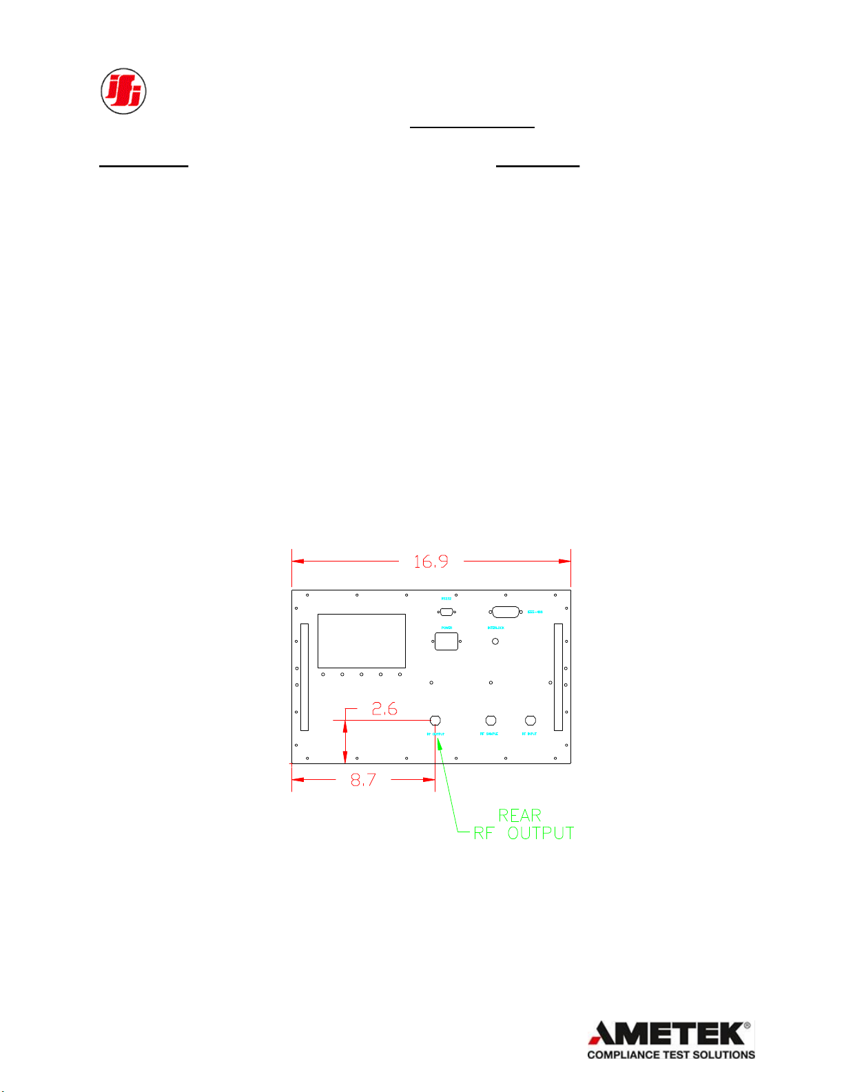
Front Panel: Rear Panel:
POWER ON/OFF Ckt Bkr AC PWR, IEC or MS Power Connector
Touchscreen Display USB
RF Input, N Type Female
FWD Sample Port, N Type Female
IEEE-488, Connector
RS232 Remote Control
Ethernet Remote Control
Interlock
RF Output , WRD750
FIGURE 3.0
REAR PANEL ILLUSTRATION
Page
9
Page 10

4.7.1 TOUCHSCREEN SOFT KEYS
INDICATOR FUNCTION
Fault : The FLT RST illuminates Red when either the Helix or the Collector
Power Supplies deviate from the design parameters. The Amplifier will
revert to AMP OFF mode. It also illuminates when either a Thermal or
Airflow condition occurs outside design parameters. Should an
excessive temperature condition occur while monitoring the TWT
temperature of the Heatsink, the Amplifier will revert to AMP OFF
mode. The Touchscreen will indicate which fault had occurred.
TOTAL/OPRT HOUR Elapsed time Indication on the Touchscreen, presents total hours that
the TWT Filament or Beam has been energized.
LOC RMT The LOC / RMT indicates, when illuminated Green, that the amplifier
is in the remote-control mode of operation via any Remote Control.
GPIB (xx) The address selection can be done through the front panel using the
touchscreen display. Holding the GPIB softkey will change the address
BAND 1/BAND 2 (OPT129) This optional feature allows the use of an Harmonic Filter to the limit
the TWT Harmonics. Band 1 is the default through Band and Band 2 is
filtered Band.
ALC ON/OFF (OPTIONAL) The ALC ON/ OFF is for Automatic Leveling Control this Optional
Feature levels the Power Based on the FWD Power Indication. The unit
must Have the Gain Control Feature in order for the ALC to function
4.7.2 CONTROLS
CONTROL FUNCTION
Power ON / OFF Circuit Breaker to turn ON/OFF main prime power to the Amplifier.
OFF/ON The Touchscreen OFF/ON softkey is a momentary switch which, when
pressed to ON position, Filament and Collector supplies are energized
after the Filament time out.
STBY / OPRT When set to OPERATE mode it turns TWT Beam ON, when
set to STBY it turns TWT Beam OFF.
FLT/RST When a Fault occurs the touchscreen button FLT/RST will turn Red.
Pressing this will reset the fault
Page
10
Page 11
4.7 TWT OPERATING INSTRUCTIONS
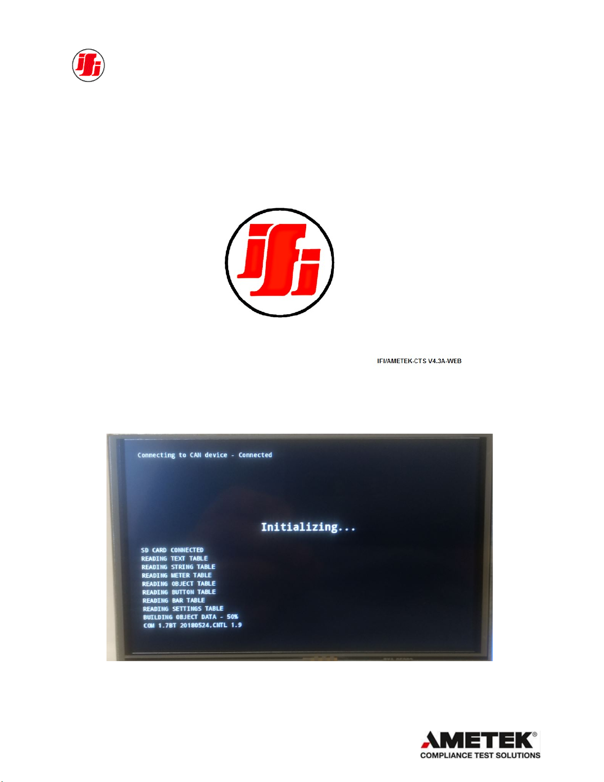
A) Apply power to the unit using the front panel ON/OFF switch. After 5 secs the splash screen will
display. Once it displays the Boot-up will start .
Figure 4.0, Front Panel Display – Splash Screen
Figure 4.1, Front Panel Display –Boot-Up
Page
11
Page 12

Start-Up Menu
After Boot-up the Start-up Menu will show and the amplifier can be controlled either Remotely or
Manually. Figure 5 is a typical screen customized to the amplifier
Figure 5.0, Front Panel Display – OFF Screen
Page
12
Page 13

Turning ON the Amplifier
FIGURE 7.0 – TURNING ON THE AMPLIFIER (Typical)
1. Press the OFF/ON Softkey .The unit will immediately start the “FILAMENT WARMUP” and
will start the countdown starting with the required time for the applicable TWT incorporated
in the amplifier. In this mode the Filament and Grid (if applicable) supplies will be energized.
2. After the time out, the High Voltage supplies will energize and at that point, if no faults exist,
the STANDBY (STBY/OPRT) mode will be highlighted Yellow.
3. The display will show the Helix and Collector voltages as seen in Figure 8.0.
Page
13
Page 14

FIGURE 8.0 – STANDBY MODE (Typical)
1. Place the unit in OPERATE (OPR) mode. In this mode the TWT will be turned ON.
2. The display will show the Helix and Collector currents as per TWT operating data sheet
FIGURE 9.0 – OPERATE MODE (Typical)
Page
14
Page 15

FAULTS: All Hard Faults will display in the Status Bar and the Actual Fault will be listed in the
Fault Bar. After a Hard Fault to regain control the amplifier the FLT/RST softkey must be
pressed. This will put the amplifier in the OFF Mode and you must restart the amplifier.
Soft Faults such as VSWR Limit or Interlock Open will only show up in the STATUS bar and
turns the amplifier to STANDBY. Once the fault is cleared the amplifier can immediately return
to OPERATE
FIGURE 10.0– FAULT SCREEN
Page
15
Page 16

OPTION 129S (HARMONIC FILTER) : If the amplifier is configured with Harmonic Filters,
the screen will have a Band selection. Band 1 is usually configured as the through Band. This is
done as protection, so the filter is not driven out of Band. Band 2 is the Harmonic Filter Band,
The Band Frequency limits will be displayed on the Front Panel and also recorded on the data
sheet.
FIGURE 11.0A – OPERATE MODE BAND 1
FIGURE 11.0B – OPERATE MODE BAND 2
Page
16
Page 17

4.8 DATA SHEETS
Provided with each Amplifier are specific Test Data Sheets measured from the amplifier using a
calibrated 50 Ohm Pad to assist the operator in maximizing the performance of the Wide Band
Amplifier.
The accuracy of the Metering is ± .5 dB ( nominal ) so to provide the operator with the ability to
maximize the performance of the wide band amplifier.
The Test Data Sheets are located within Appendix A
Page
17
Page 18

SECTION 5.0
PRINCIPLES OF OPERATION
5.1 PROPER USAGE AND WARNINGS
5.1.1 Controlling Power Output
With a nominal 50 ohm resistive load and an input signal appropriate to produce a power output
within the limitations specified above, the amplifier may be placed in operation. To interrupt the
output, simply interrupt the input signal. The amplifier may be run indefinitely at rated output.
Output power is usually measured with a power meter and suitable power Termination.
5.1.2 Input Signal Levels
The Amplifier is designed to operate with less than a 0 dBm (1.0 mW) input signal. It is not
advisable to over drive any amplifier and depend on protection circuits to maintain proper gain
control. IFI makes available with each shipped amplifier specific data and curves so the operator will
know the proper input signal levels to more efficiently operate the amplifier, refer to Paragraph 4.7
herein.
5.2 Features
5.2.1 Preamplifier
The Preamplifier provides the proper drive levels to the TWT to obtain the proper Output Power.
The preamplifier is powered from a low voltage power supply that is independent of the main power
supply.
5.2.2 Power Amplifier
The Power amplifier consists of TWT as the main amplification stage. It is powered by several
power supplies; Filament supply, Helix supply and Collector supply.
Page
18
Page 19

SECTION 6.0
6.1 INTRODUCTION
The Instruments For Industry, Inc. (IFI) Amplifiers can be operated remotely from a computer
having IEEE-488 (GPIB), RS-232, USB or ETHERNET. These interfaces will allow the
amplifier to be remotely controlled by sending commands to the amplifier. Additionally, the
amplifier status and forward and reverse power readings may be read over the remote.
6.2 IEEE-488.2 INTERFACE
The IFI Amplifiers have the IEEE-488.2, General Purpose Interface Bus (GPIB) interface. All
amplifier functions can be controlled by coded messages sent over the interface bus via the
24-pin socket connector on the rear panel of the unit. IEEE-488.2 Standard is implemented,
which defines the protocols and syntax of commands. The GPIB command codes for the IFI
Amplifier series are discussed on subsequent pages and, for ease of identification; the
command codes are identified within the text by bold capital characters. For full information
on the IEEE protocols and syntax, the IEEE-488.2 Standard should be consulted.
6.2.1 GPIB Address
Each amplifier has a unique GPIB address that allows communication to the amplifier on a
multi-bus interface (like GPIB). The GPIB address of the amplifier is set by via the Front
panel using the Control knob at the start up menu. Select an address that is different than the
addresses of any other instruments on the GPIB bus.
6.2.2 Using National Instruments’ GPIB Controllers
In order for the amplifiers to operate correctly with a National Instruments GPIB controller
card, the following must be done: (Items 1-5 are done in the IBCONF program.)
1. Set "Terminate reads on EOS" to yes.
2. Set "Set EOI with EOS on Writes" to yes.
3. Set the EOS byte to 0Ah (an ASCII line feed character).
4. Set "Send EOI at end of writes" to yes.
5. Set "Enable repeat addressing" to yes at the board level.
6. When sending command strings to the amplifier, a carriage return character (0Dh)
followed by a line feed character (0Ah), must always be appended to the command,
IEEE-488.2 INTERFACE
Page
19
Page 20

otherwise the amplifier will wait indefinitely for the CR-LF combination. If
this happens the unit will have to be powered off and back on to reset this
condition. (The interface device will automatically assert the EOI line during the LF if
items 2 - 4, above, are set to yes in the IBCONF program.) As an example, when issuing
the zero attenuation command using the IBIC or WIBIC program, the command string
would look like this: "ZA\r\n". (The \r is National Instruments' notation for the carriage
return, and the \n is the line feed or 'new line' character.) Notice that the commands are
upper case only.
6.3 RS-232 INTERFACE
RS-232, a standard which defines the communication between DTE, data terminal equipment
to DCE, data communication equipment. The IFI Amplifiers have a RS-232, serial interface.
All amplifier functions can be controlled by coded messages sent over the interface bus via the
9-pin D-type socket connector on the rear panel of the unit.
1.3.1 RS-232 Wiring
Connect the serial port of the amplifier to a computer using a null modem cable or a standard
serial cable with a null modem adapter.
Pin #s Signal Name Remote Terminal I/O
2 TXD Output to remote terminal
3 RXD Input from remote terminal
5 Signal GND Signal reference
The RS-232 Serial Communication Settings:
Baud Rate: 9600 Baud.
Data Bits: 8
Parity: None
Stop bits: 1
Flow control: None
6.4 RS-422 / RS-485 INTERFACE
The IFI Amplifiers have the RS-422 and RS-485, serial interfaces. All amplifier functions can
be controlled by coded messages sent over the interface bus via the 9-pin D-type (RS-422) and
RJ-11 (RS-485), connector on the rear panel of the unit.
6.4.1 RS-422/RS-485 Wiring
Connect the RS-422/RS-485 port of the amplifier to a computer cable.
The RS-422/RS-485 Serial Communication Settings:
Page
20
Page 21

Baud Rate: 9600 baud.
Data Bits: 8
Parity: None
Stop bits: 1
Flow control: None
6.5 ETHERNET INTERFACE [when applicable]
The IFI Amplifiers have an Ethernet Interface. All amplifier functions can be controlled by
coded messages sent over the interface bus via RJ-45 connector on the rear panel of the unit.
1.5.1 Description
The Ethernet Interface allows the IFI Amplifiers to communicate with and participate in a
Local Area Network using RJ-45 cable.
The Internet protocol suite (commonly TCP/IP) is the set of communications protocols that
implement the protocol stack on which the Internet and most commercial networks run. It is
named for two of the most important protocols in it: the Transmission Control Protocol (TCP)
and the Internet Protocol (IP), which were also the first two networking protocols defined.
Today's IP networking represents a synthesis of two.
TCP/IP uses four numbers to address a computer. Each computer must have a unique four
numbers address. The numbers are always between 0 and 255. Addresses are normally written
as four numbers separated by a period like this: 192.168.1.50.
The Ethernet interface is a cable bus which runs over copper or fiber. The copper interfaces
use either a coaxial cable or differential twisted pairs. The Ethernet network is defined by
IEEE 802.3 standard. Descriptions for each of the physical lines are provided below.
Ethernet Bus 10/100BaseT Pin-Out
Name Pin Cable Color Pin Name
TX+ 1 White/Orange 1 TX+
TX- 2 Orange 2 TX-
RX+ 3 White/Green 3 RX+
4 Blue 4
5 White/Blue 5
RX- 6 Green 6 RX-
7 White/Brown 7
8 Brown 8
Page
21
Page 22

6.6 REMOTE COMMAND FORMAT
The IFI Amplifiers remote commands are a string of ASCII characters with the following
format:
Command Code End Of String Characters
The Command Code is a three to nine characters command code which the system interprets
to determine the type of action to take. See Remote commands below.
The End of String characters are two ASCII characters, a carriage return character (0D hex)
followed by a line feed character (0A hex) that must follow the command code for all
commands.
NOTES:
1. ALL COMMANDS AND REQUESTS MUST CONSIST ENTIRELY OF UPPER
CASE ALPHANUMERIC CHARACTERS.
2. ALL VALUES DISPLAYED DO NOT SHOW THE ZEROS TO THE LEFT OF THE
NUMBER VALUE.
1.6.1 Remote/Local Control
When the amplifier receives a command over the remote interface, it automatically switches
to REMOTE operation, pressing the LOCAL key on the front panel returns the unit to normal
manual local operation. Optional mode is when the computer host must send a REMOTE
command for the amplifier to go remote. In this option all status commands can be read while
the amplifier is in local mode and they will not revert the amplifier to remote. An additional
LOCAL command is applied to put amp in local mode if it was set for remote operation
Page
22
Page 23

1.6.2 REMOTE COMMANDS
IEEE COMMANDS FOR TWTA
Code TWTA function
OFF AMP OFF
ON
STBY
OPRT
RESET
AMP ON
Standby
Operate
Fault Reset
ATTUxx Increase Attenuation (xx- # of steps) [Response with Gain value, ‘GAIN: XXXXX
%’](optional)
ATTDxx Decrease Attenuation (xx- # of steps) [Response with Gain value, ‘GAIN:
XXXXX %’](optional)
BAND Selects Band of Operation & Returns, ‘XXXXXXXXXXXXXXXX’ [Optional]
REQUEST STATUS
Code AMPLIFIER STATUS
STATUS OFF
FAULT
STANDBY INTERLOCK OPEN
REMOTE OPERATION DISABLED
EXCESS PULS W [ In Pulse unit only ]
EXCESS DTY CYC [ In Pulse unit only ]
ON-WARMUP
OPERATE
FAULT
INTERLOCK OPEN
HIGH VSWR
Returns Detailed Message
THERMAL FAULT
HIGH HELIX CURRENT FAULT
HELIX VOLTAGE FAULT
COLLECTOR CURRENT FAULT
COLLECTOR VOLTAGE FAULT
LOW AIRFLOW FAULT
Page
23
Page 24

POWER AND METERING - STATUS RESPONSES FOR AMP
CODE TWTA FUNCTION
POWERFWD
Returns Forward Power Value in Watts, ‘POWER FWD: XXXXX W’
POWERRFL Returns Reflected Power Value in Watts, ‘POWER RFL: XXXXX W’
HELIXV Returns Helix Volts Value in Volts, ‘HELIXV: XXXXX V’
HELIXI Returns Helix Current Value in milliamps, ‘HELIXI: XXXXX mA’
COLLV Returns Collector Volts Value in Volts, ‘COLLV: XXXXX V’
COLLI Returns Collector Current Value in milliamps, ‘COLLI: XXXXX mA’
FILAMENTV Returns Filament Volts Value in Volts, ‘FILAMENT V: XXXXX V’
[Optional]
GRIDV Returns Grid Volts Value in Volts, ‘GRID V: XXXXX V’ [Optional]
FILAMENTH Returns Filament Hours Value, ‘FIL HRS: XXXXX’
BEAMH Returns Beam Hours Value, ‘BEAM HRS: XXXXX’
PULSEW Returns Pulse Width Value, ‘PULS W: XXXXX.X uS’ [ In Pulse unit only ]
FRQNCY Returns Pulse Frequency Value, ‘REP RATE: XXXXXX Hz’ [ In Pulse
unit only ]
DUTYCYC Returns Duty Cycle Value, ‘DTY CYC: XXXXX %’ [ In Pulse unit only ]
ZEROATT Sets the Amplifier for ZERO Attenuation & Returns, ‘GAIN: 00100 %’
[Optional]
FULLATT Sets the Amplifier for FULL Attenuation & Returns, ‘GAIN: 00000 %’
[Optional]
MODEL
SN
*IDN?
Returns ASCII response comprising of four data fields in the format
Returns Model number of the unit
Returns Serial number of the unit
<Manufacturer>, <Model>, <Serial Number>, <Firmware Version>
*RST
Reset Command, Sets the Amplifier to the factory default power up state
(reboots MPU)
Page
24
Page 25

1.7 REMOTE EXAMPLE CODE
RS-232 USB or Ethernet, Example using Hyper-terminal
1. Connect serial port of amplifier to computer using a null modem cable or a standard serial
cable with a null modem adapter.
2. Use a program such as Hyper-terminal to communicate with the amplifier. (To find Hyper-
terminal go to Start Programs Accessories Communications Hyper Terminal,
and click on Hyper terminal.
To setup Hyper terminal follow the directions below.
When Hyper terminal runs a setup dialog box will open:
For RS-232:
2.1 Enter a name and choose an icon. Click OK.
2.2 In the Connect Using box select your Comm. port (Ex. “Direct to Com1” or
“Com1”) for RS-232 or TCP/IP for Ethernet remote. Click OK.
2.3 In Bits per Second select “9600”.
2.4 In Data Bits select “8”.
2.5 In Parity Select “None”.
2.6 In Stop bits select “1”.
2.7 In Flow control select “None”
2.8 Click OK.
For Ethernet:
2.1 Enter a name and choose an icon. Click OK.
2.2 In the Connect Using box select TCP/IP for Ethernet remote. Click OK.
2.3 Enter an IP Address in Host Address box and 10001 in Port Number box. Click
OK.
3. If you use Hyper-terminal steps 2.1 to 2.8 will set up Com1 to communicate at 9600 baud,
8 bits, and no parity with 1 stop bit and steps 2.1 to 2.3 will set up Ethernet to
communicate at 57600 baud.
4. Turn amplifier line power ON.
5. To place the amplifier in remote operation type in a valid command such as “STATUS”
and then hit the “Enter” key. The amplifier will then go into remote operation and the
status will be displayed on the computer.
Page
25
Page 26

6.8 See the section 1.6.2 REMOTE COMMANDS for the list of usable commands and
responses.
REMOTE EXAMPLES
Command to read the amplifiers status:
ASCII String to amplifier: STATUS(cr)(lf)
Hex equivalent of string: 0x53,0x54,0x41,0x54,0x55,0x53,0x0d,0x0a
Action: None
Response: Responds with the amplifiers current status.
Example of response: STANDBY(cr)(lf)
Hex value of example response: 0x53,0x54,0x41,0x4e,0x44,0x42,0x59,0x0a,0x0d
Command to place unit in operate mode:
ASCII String sent to amplifier: OPRT(cr)(lf)
Hex equivalent of string: 0x4f, 0x50, 0x52, 0x54,0x0d,0x0a
Action: The amplifier will go to Operate mode if the amplifier was previously in Standby mode.
Response: None
Example of response: N/A
Hex value of example: N/A
Command to read the amplifiers forward power:
ASCII String to amplifier: POWERFWD(cr)(lf)
Hex equivalent of string: 0x50,0x4f,0x57,0x45,0x52,0x46,0x57,0x44,0x0d,0x0a
Action: None
Response: Responds with the amplifiers forward power reading.
Example of response : POWER FWD: 09005 W(cr)(lf)
Hex value of example response :
0x50,0x4f,0x57,0x45,0x52,0x20,0x46,0x57,0x44,0x3a,0x20,0x30,0x39,0x30,0x30,0x35,0x2
Page
26
Page 27

Controlling the amplifier with the web-based interface
You can control the amplifier remotely via a web-based interface through a web browser.
IMPORTANT Please note that the amplifier and computer must be on the same local network.
Obtaining the amplifiers IP address
Connect the amplifier to a network by inserting an ethernet cable, and then turn the unit on.
Once you are at the main display, you should note in the top right corner the IP address of the
amplifier.
Page
27
Page 28

Accessing the web-based amplifier interface
Enter the amplifier’s IP address in the address bar of your web browser, using the following format,
and then press [ENTER]
http://[IP Address]:8000
At this point, any action performed via the web interface or the amplifier’s display, will show in each
of the screens.
Changing the amplifiers IP address
Page
28
Page 29

To change the IP address of the amplifier to a static IP, you can access the ethernet configuration
menu of the amplifier from the front display, or remotely.
From the front display:
- Press and hold the [LOC/RMT] button for 8 seconds, and you will be
prompted with the following ethernet configuration menu
Primary Ethernet
IP Address Displays the current IP address of the amplifier
Subnet Mask Displays the current Subnet Mask of the amplifier
Default Gateway By default, this field is left unpopulated*
Static IP Off by default. Enable to set a static IP address
Secondary Ethernet
IP Address Displays the IP address of the secondary ethernet controller
Subnet Mask Displays the Subnet Mask of the secondary ethernet controller
*Default Gateway only needs to be entered for Static IP configuration
Page
29
Page 30

Cross
-
Over
Direct Cross-Over Communication with Ethernet
Should you want to communicate with the amplifier directly, using a desktop or laptop pc, you can
accomplish this by using a cross-over ethernet cable.
It is recommended that you first issue an IP to the amplifier via a routers DHCP server, and then configure
the amplifier with a static IP.
Initial Configuration
The MPU by default is set to obtain an IP address automatically from a local DHCP server (such as a
router).
Both the computer being used to send commands, and the MPU, must be on the same local network.
For testing purposes, the following configurations were used.
Configuration 1 – Network Router
The computer and MPU are plugged into two separate ports of a router (Linksys BEFSR81). A router by
default is set to act as a local DHCP server and should work out of box in this way. The router was
modified to only issue IP addresses within a specific range of 192.168.1.50 through 192.168.1.99.
PC IP = 192.168.1.51
MPU IP = 192.168.1.50
Using HyperTerminal, a remote connection using Ethernet was established to begin testing.
Once connected, the following commands were issued to verify functionality.
- STATUS
- *IDN?
- OPRT
- STBY
Following this, the MPU was then configured with a static IP address using the SETTINGS -> EDIT
commands. The following values were set:
- STATIC IP = Y
- STATIC IP Value = 192.168.1.64
- SAVE SETTINGS = Y
Page
30
Page 31

The MPU was then rebooted with the *RST commanded, and it was verified that the MPU display
showed the correct static IP address.
Using HyperTerminal, a remote connection was established again, and the same commands listed above
were retested.
Following this test, the MPU was reset to receive an IP from the DHCP server. Again, using the SETTINGS
-> EDIT commands. The following values were set:
- STATIC IP = N
- STATIC IP Value = 1.1.1.1
- SAVE SETTINGS = Y
The MPU was then rebooted again and it was verified that the IP had changed to a dynamic IP address.
MPU IP = 192.168.1.50
PC IP = 192.168.1.51
Configuration 2 – Network Router + Network Switch
The PC and MPU were disconnected from the router and hooked up to a network switch (Linksys
SRW224G4) and used in an unmanaged mode (standard switch configuration). A single CAT5E cable was
ran from the router to the switch.
Following turn on of all the equipment, the following IP addresses were issued:
MPU IP = 192.168.1.51
PC IP = 192.168.1.50
A remote connection, via Ethernet, was reestablished with the MPU and the same commands were sent
to verify functionality.
Following this, the MPU was then configured with a static IP address again using the SETTINGS -> EDIT
commands. The following values were set:
- STATIC IP = Y
- STATIC IP Value = 192.168.1.96
- SAVE SETTINGS = Y
The MPU was then rebooted, and the correct static IP value was displayed on the front display of the
MPU.
Using HyperTerminal, a remote connection was established again, and the same commands listed above
were retested.
Once complete, the MPU was reset to accept a DHCP IP address, and once rebooted, the IP address of
the MPU went back to 192.168.1.51
Page
31
Page 32

SECTION 7.0
MAINTENANCE AND SERVICING
7.1 PERIODIC MAINTENANCE
The only periodic maintenance required on the TWT amplifier system is insuring that the cooling
vents are not obstructed in such a manner that the airflow is restricted. Periodic cleaning of the vents
may be required depending on the degree of dust in the atmosphere.
7.2. SERVICING THE AMPLIFIER
Servicing of the amplifier by the operator is not recommended. Most of the internal circuitry requires
special and unique test instruments to trouble shoot, align and calibrate the circuits. Should servicing
be required, refer to Paragraph 7.3.
7.2.1 TROUBLESHOOTING
PROBLEM CAUSE SOLUTION COMMENTS
TOUCHSCREEN display
blank
Amp will not go to Operate
mode
Helix supply fault after
warm-up time
Helix Supply fault when
turning amplifier to OPRT
mode.
Collector supply fault Collector supply faulty Check Collector voltage output
Air Flow fault No sufficient Air-inlet Move any obstructions from air
Thermal fault Over-heating Make sure airflow is adequate
No service voltages Check line power.
Check service voltages,
+12VDC, -12VDC, 5VDC
Door interlock open,
High VSWR
Helix Power supply faulty Check Helix voltage output
HV arcing (Overcurrent
fault).
TWT gassy
Check that door interlock BNC
connector is terminated with
either 50 Ohms or short.
Check RF output termination
connection.
without TWT connected
Disconnect TWT and operate
amplifier. Check for arcing if
fault consist.
Degas TWT by leaving Amp in
STBY mode for few hours.
without TWT connected
inlet sections
and ambient temperature within
the limit.
Connect AC line to
specified Prime power
source.
Refer to S/N tag on unit
When operating any RF
amplifier proper
termination must be
connected to the RF output
connector.
Check on the
TOUCHSCREEN display
for the fault description.
Danger High Voltages
TWTA must be turned ON
at least once a month, so to
eliminate TWT gassing up.
Check on the
TOUCHSCREEN display
for the fault description.
Danger High Voltages
Page
32
Page 33

7.3 EQUIPMENT RETURN PROCEDURE
Should such an event arise that the Amplifier requires repair or calibration, it is recommended that the
reader follow the Equipment Return Procedure so the equipment can be repaired or calibrated and
returned in a efficient and timely manner.
7.3.1 Request a RMA Number
Contact the IFI Service Department either in writing or by calling (631) 467-8400 and request a
Return Material Authorization (RMA) Number. The RMA Number is the method IFI uses to prepare
its' services for returned material in transit and acts as a tracking document for the returned material
through the repair or calibration process. The RMA also documents the customers' specific
instructions or reason related to the return of the material.
7.3.2 Return All Accessories
In the interest of saving time and expediting the repair or calibration process, return all the associated
accessories described in Section 1.0 when returning the equipment for repair or calibration. In many
cases, a faulty accessory could give the illusion that the equipment itself has failed. For this reason it
is important to return the all the accessories with the equipment. It is also IFI's policy to verify
performance of all associated accessories of Section 1.0 before returning the equipment to service.
7.3.3 Packaging The Equipment
When returning equipment to the manufacturer, always wrap each accessory separately and provide
sufficient protective material around each item to prevent damage from handling and shipping
conditions.
7.3.4 Reference The RMA Number
As detailed in Paragraph 7.3.1, always reference the IFI assigned RMA Number on your Packing List
and Purchase Order and also when any inquiries are made.
Page
33
Page 34

APPENDIX A
TEST DATA SHEETS
Page
34
Page 35

APPENDIX B
Drawings Package
900874 INTERCONNECT DIAGRAM
Page
35
 Loading...