

Page 1

Daughter Card with SATA to IDE & CF Type II Converter
SAIDE-KIT01
Quick Installation Guide
Version 1.0
May 12, 2008
Package Contents
SAIDE-KIT01 package includes the following items:
z 1 x SAIDE-KIT01 Daughter Card
z 1 x Power Cable
z 1 x QIG (Quick Installation Guide)
©2006 Copyright by IEI Technology corp.
All rights reserved.
1
Page 2

Specifications
z Daughter Card with SATA to IDE & CF Type II Converter
Only one IDE or CF device can be install and use in the same time.
z Chipset: JMicron JM20330
z Compliance to Serial ATA Generation1
z ATA/ATAPI PIO mode 0 to 4
z ATA/ATAPI Ultra DMA transfer rate up to 150MB/s
z 3.5-inch Hard Disk Drive and ATAPI Optical Storage
z Compliance with CFI/II and Micro Drive
z LED Indicator for Power Linked. SATA Linked and HDD Activity
z Mount in bracket.
z Serial ATA Hot Plug
z Connector:
1 x 40-pin IDE connector
1 x CF Type II connector
1 x Serial ATA Port
1 x 4-pin power connector
z Temperature: Operation: 0 ~ 60° C (32 ~ 140° F)
z Humidity: Operation: 5% ~ 95% non-condensing
z Dimension: 85.8(L) mm x 69.1(W) mm
Ordering Information
SAIDE-KIT01-R10
Daughter Card with SATA to IDE & CF Type II Converter
2
Page 3

Jumpers Setting and Connectors
PW1: Power Connector
PIN Description
1 N/C
2 GND
3 GND
4 +5V
SATA1: Serial ATA Connector
PIN Description
1 GND
2 TXP
3 TXN
4 GND
5 RXN
6 RXP
7 GND
IDE2: 2X20 Pin IDE Connector (P=2.54)
PIN Description PIN Description
1
3
5
7
9
11
13
15
17
19
21
23
25
27
29
31
33
35
37
39
RESET#
DATA 7
DATA 6
DATA 5
DATA 4
DATA 3
DATA 2
DATA 1
DATA 0
GROUND
DMARQ
IOW#
IOR#
IORDY
DMACK#
INTERRUPT
SA1
SA0
HDC CS0#
HDD ACTIVE#
2
4
6
8
10
12
14
16
18
20
22
24
26
28
30
32
34
36
38
40
GROUND
DATA 8
DATA 9
DATA 10
DATA 11
DATA 12
DATA 13
DATA 14
DATA 15
N/C
GROUND
GROUND
GROUND
GROUND
GROUND
N/C
PDIAG#
SA2
HDC CS1#
GROUND
3
Page 4
I
CF1: Compact Flash Storage Card Socket
PIN Description PIN Description
1
2
3
4
5
6
7
8
9
10
11
12
13
14
15
16
17
18
19
20
21
22
23
24
25
GROUND
DATA 3
DATA 4
DATA 5
DATA 6
DATA 7
CS1#
N/C
GROUND
N/C
N/C
N/C
VCC
N/C
N/C
N/C
N/C
SA2
SA1
SA0
DATA 0
DATA 1
DATA 2
N/C
IDE_DETECT
26
27
28
29
30
31
32
33
34
35
36
37
38
39
40
41
42
43
44
45
46
47
48
49
50
IDE_DETECT
DATA 11
DATA 12
DATA 13
DATA 14
DATA 15
CS3#
N/C
IOR#
IOW#
VCC
IRQ15
VCC
MASTER
N/C
RESET#
IORDY
DMARQ
DMACK#
ACTIVE#
PDIAG#
DATA 8
DATA 9
DATA 10
GROUND
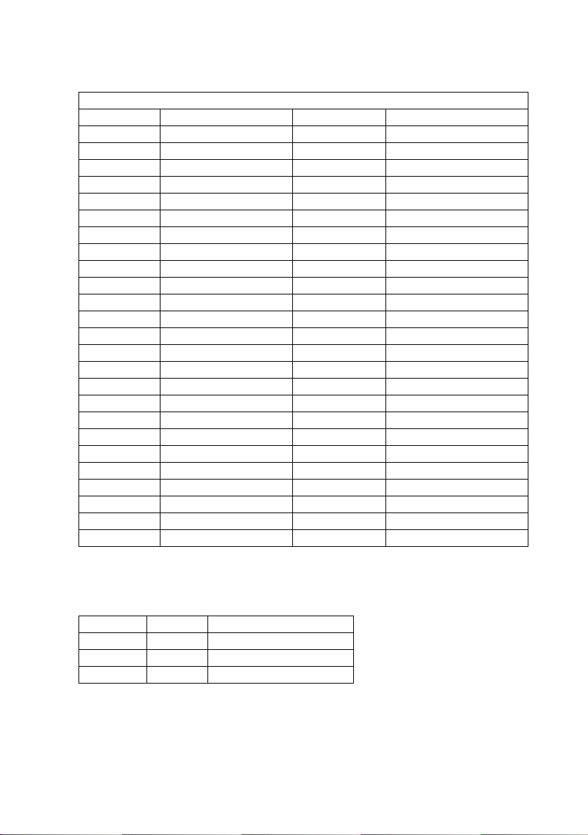
LED Indicator
Location Status Description
LED1 Red Power Linked
LED2 Green SATA Linked
LED3 Green HDD Activity
4
Page 5
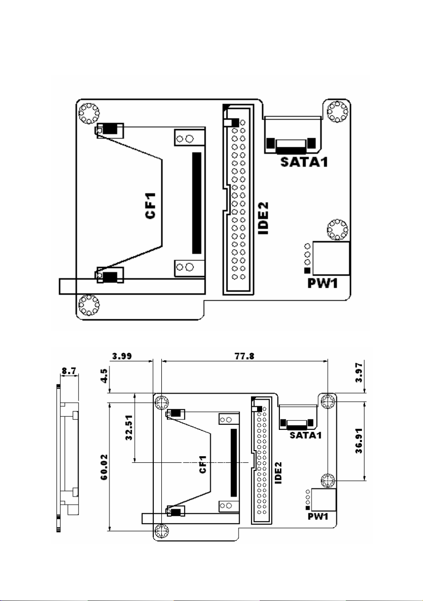
Board Layout: Jumper and Connector Locations
5
 Loading...