

Page 1
ROCKY-3786EV CPU Card
ROCKY-3786EV CPU Card
IEI Technology Corp.
MODEL NAME
MODEL:
ROCKY-3786EV
PICMG Socket 370 133 MHz FSB CPU Card
with VGA, LAN, GbE, USB 2.0, Audio and SATA RAID
User Manual
Rev. 4.10 – 25 September, 2009
Page 1
Page 1
Page 2
ROCKY-3786EV CPU Card
Revision
Date Version Changes
25 September, 2009 4.10 Changed SATA chip to VIA VT6421A
28 September, 2006 4.00 Initial release
Page 2
Page 2
Page 3

ROCKY-3786EV CPU Card
MODEL NAME
Table of Contents
1 INTRODUCTION........................................................................................................ 12
1.1 ROCKY-3786EV CPU BOARD OVERVIEW.............................................................. 13
1.1.1 ROCKY-3786EV Model Variations.................................................................. 13
1.1.2 ROCKY-3786EV CPU Board Applications...................................................... 13
1.1.3 ROCKY-3786EV CPU Board Benefits............................................................. 13
1.1.4 ROCKY-3786EV CPU Board Features............................................................ 13
1.2 ROCKY-3786EV CPU BOARD OVERVIEW.............................................................. 14
1.2.1 ROCKY-3786EV CPU Board Connectors........................................................ 14
1.2.2 Technical Specifications: ................................................................................. 15
2 DETAILED SPECIFICATIONS................................................................................ 17
2.1.1 Pentium® III.................................................................................................... 18
2.1.2 Celeron®.......................................................................................................... 19
2.1.3 VIA® C3........................................................................................................... 19
2.2 ONBOARD CHIPSETS................................................................................................. 20
2.2.1 Northbridge and Southbridge Chipsets ........................................................... 20
2.2.2 Intel® 815E Northbridge Chipset.................................................................... 20
2.2.3 Intel® ICH2 Southbridge Chipset.................................................................... 21
2.3 DATA FLOW.............................................................................................................. 24
2.4 GRAPHICS SUPPORT.................................................................................................. 24
2.5 MEMORY SUPPORT ................................................................................................... 25
2.6 PCI BUS INTERFACE SUPPORT.................................................................................. 25
2.7 10/100/1000MBPS ETHERNET.................................................................................. 26
2.8 DRIVE INTERFACES .................................................................................................. 27
2.8.1 SATA Drives..................................................................................................... 27
2.8.2 IDE HDD Interfaces........................................................................................ 27
2.8.3 Floppy Disk Drive (FDD)................................................................................ 27
2.8.4 Compact Flash Support ................................................................................... 27
2.9 SERIAL PORTS .......................................................................................................... 28
2.10 REAL TIME CLOCK................................................................................................. 28
2.11 INFRARED DATA ASSOCIATION (IRDA) INTERFACE ................................................ 28
2.12 USB INTERFACES ................................................................................................... 28
Page 3
Page 3
Page 4

2.15 AUDIO CODEC........................................................................................................ 29
2.16 POWER CONSUMPTION........................................................................................... 30
2.17 PACKAGED CONTENTS AND OPTIONAL ACCESSORY ITEMS..................................... 30
2.17.1 Package Contents........................................................................................... 30
2.17.2 Optional Accessory Items............................................................................... 31
3 CONNECTORS AND JUMPERS.............................................................................. 32
3.1 PERIPHERAL INTERFACE CONNECTORS..................................................................... 33
3.1.1 ROCKY-3786EV CPU Board Layout............................................................... 33
3.1.2 Peripheral Interface Connectors ..................................................................... 33
3.1.3 Rear Panel Connectors.................................................................................... 35
3.1.4 Onboard Jumpers............................................................................................. 35
3.2 INTERNAL PERIPHERAL CONNECTORS ...................................................................... 36
3.2.1 ATX Power Connector ..................................................................................... 36
3.2.2 ATX Power 5VSB and PSON connector .......................................................... 37
ROCKY-3786EV CPU Card
3.2.3 ATX Power Switch Connector.......................................................................... 38
3.2.4 Audio Connector .............................................................................................. 39
3.2.5 CD In Connector.............................................................................................. 40
3.2.6 Compact Flash Socket...................................................................................... 41
3.2.7 CPU Fan Connector........................................................................................ 43
3.2.8 CRT Connector ................................................................................................ 44
3.2.9 FDD Connector ............................................................................................... 44
3.2.10 IDE Interface Connectors.............................................................................. 46
3.2.11 IrDA Connector.............................................................................................. 48
3.2.12 Keyboard Connector...................................................................................... 49
3.2.13 LAN LED Connector...................................................................................... 50
3.2.14 Multi Panel Connector................................................................................... 51
3.2.15 Parallel Port Connector ................................................................................ 52
3.2.16 SATA Drive Ports........................................................................................... 53
3.2.17 Serial Port Connectors .................................................................................. 54
3.2.18 Internal USB 1.1 Connector .......................................................................... 55
3.2.19 Optional USB 2.0 Connectors........................................................................ 56
3.3 EXTERNAL (REAR PANEL) CONNECTORS.................................................................. 57
3.3.1 Audio Line Out Connector............................................................................... 58
3.3.2 10/100Mbps Ethernet Connector..................................................................... 58
3.3.3 Optional 1Gb Ethernet Connector................................................................... 59
Page 4
Page 4
Page 5

ROCKY-3786EV CPU Card
3.3.4 Keyboard/Mouse Connector............................................................................ 60
3.3.5 VGA Connector................................................................................................ 60
3.4 ONBOARD JUMPERS ................................................................................................. 62
3.4.1 Clear CMOS Jumper........................................................................................ 63
3.4.2 BIOS Protection Selection Jumper .................................................................. 63
3.4.3 Keyboard Power Selection Jumper.................................................................. 64
3.4.4 CF Mode Selection Jumper.............................................................................. 64
4 INSTALLATION AND CONFIGURATION ............................................................ 67
4.1 INSTALLATION CONSIDERATIONS.............................................................................. 68
4.1.1 Installation Notices.......................................................................................... 68
4.2 UNPACKING.............................................................................................................. 69
4.2.1 Unpacking Precautions.................................................................................... 69
4.2.2 Checklist........................................................................................................... 69
4.3 ROCKY-3786EV CPU CARD INSTALLATION .......................................................... 70
MODEL NAME
4.3.1 CPU Installation.............................................................................................. 71
4.3.2 Socket 370 Cooling Kit Installation................................................................. 72
4.3.3 DIMM Module Installation.............................................................................. 74
4.3.3.1 Purchasing the Memory Module............................................................... 74
4.3.3.2 DIMM Module Installation....................................................................... 75
4.3.4 Peripheral Device Connection......................................................................... 76
4.3.4.1 Compact Flash Disk.................................................................................. 76
4.3.4.2 IDE Disk Drive Connector (CN1, CN7)................................................... 77
4.3.4.3 Floppy Drive Connector ........................................................................... 77
4.3.4.4 Parallel Port Connector (CN9).................................................................. 78
4.3.4.5 Audio Interface ......................................................................................... 78
4.3.4.6 COM Port Connectors [CN2, CN8].......................................................... 78
4.4 CHASSIS INSTALLATION............................................................................................ 78
4.5 REAR PANEL CONNECTORS ...................................................................................... 79
4.5.1 Ethernet Connection ........................................................................................ 79
4.5.2 Keyboard and Mouse Connection.................................................................... 79
4.5.3 VGA Connection .............................................................................................. 79
5 AW ARD BIOS SETUP................................................................................................. 80
5.1 INTRODUCTION......................................................................................................... 81
5.1.1 Starting Setup................................................................................................... 81
Page 5
Page 5
Page 6

5.1.2 Using Setup...................................................................................................... 81
5.1.3 Getting Help..................................................................................................... 82
5.1.4 Unable to Reboot after Configuration Changes.............................................. 82
5.1.5 Main BIOS Menu ............................................................................................. 82
5.2 STANDARD CMOS FEATURES .................................................................................. 85
5.2.1 IDE Primary Master/Slave .............................................................................. 88
5.3 ADVANCED BIOS FEATURES .................................................................................... 90
5.4 ADVANCED CHIPSET FEATURES................................................................................ 97
5.5 INTEGRATED PERIPHERALS..................................................................................... 101
5.6 POWER MANAGEMENT SETUP................................................................................ 106
5.7 PNP/PCI CONFIGURATIONS.....................................................................................112
5.8 PC HEALTH STATUS ................................................................................................116
5.9 FREQUENCY/VOLTAGE CONTROL............................................................................117
6 SOFTWARE DRIVERS............................................................................................ 120
ROCKY-3786EV CPU Card
6.2 ATI DISPLAY DRIVER ............................................................................................. 121
6.3 INTEL® CHIPSET DRIVER INSTALLATION ............................................................... 126
6.4 REALTEK LAN DRIVER (FOR GBE LAN) INSTALLATION ....................................... 130
A BIOS CONFIGURATION OPTIONS..................................................................... 134
A.1 BIOS CONFIGURATION OPTIONS ........................................................................... 135
B WA TCHDOG TIMER............................................................................................... 139
C EXTERNAL AC’97 AUDIO CODEC..................................................................... 142
C.1 INTRODUCTION...................................................................................................... 143
C.1.1 Accessing the AC’97 CODEC ....................................................................... 143
C.1.2 Driver Installation......................................................................................... 143
C.2 SOUND EFFECT CONFIGURATION ........................................................................... 144
C.2.1 Accessing the Sound Effects Manager........................................................... 144
C.2.2 Sound Effect Manager Configuration Options.............................................. 145
Page 6
Page 6
Page 7
ROCKY-3786EV CPU Card
MODEL NAME
List of Figures
Figure 1-1 ROCKY-3786EV CPU Board Overview..................................................................14
Figure 2-1: Data Flow Block Diagram.........................................................................................24
Figure 3-1: Connector and Jumper Locations...........................................................................33
Figure 3-2: ATX Power Connector Location..............................................................................37
Figure 3-3: ATX Power 5VSB and PSON Connector Location.................................................38
Figure 3-4: ATX Power Switch Connector Location .................................................................39
Figure 3-5: Audio connector Location........................................................................................40
Figure 3-6: CD In Connector Location........................................................................................41
Figure 3-7: CFII Socket Location.................................................................................................42
Figure 3-8 CPU Fan Connector Locations .................................................................................43
Figure 3-9: CRT Connector Location..........................................................................................44
Figure 3-10: FDD Connector Location........................................................................................46
Figure 3-11: IDE Interface Connector Locations.......................................................................48
Figure 3-12: IrDA Connector Location........................................................................................49
Figure 3-13: Keyboard Connector Location ..............................................................................50
Figure 3-14: LAN LED Connector Location ...............................................................................51
Figure 3-15: Multi Panel Connector Location............................................................................52
Figure 3-16: Parallel Port Connector Location..........................................................................53
Figure 3-17: SATA Connector Locations ...................................................................................54
Figure 3-18 Serial Port Connector Locations ............................................................................55
Figure 3-19: Internal USB 1.1 Connector Location ...................................................................56
Figure 3-20: Optional USB 2.0 Connector Locations................................................................57
Figure 3-21: ROCKY-3786EV CPU Board Rear Panel ...............................................................58
Figure 3-22: Ethernet Connector.................................................................................................59
Figure 3-23: Keyboard/Mouse Pinout locations........................................................................60
Figure 3-24: VGA Connector Pin Locations...............................................................................61
Figure 3-26: Jumper Locations...................................................................................................62
Figure 4-1: Install the CPU...........................................................................................................72
Figure 4-2: IEI Socket 370 Cooling Kits......................................................................................73
Figure 4-3: Install the CPU cooler...............................................................................................74
Figure 4-4: Installing the DIMM Module......................................................................................75
Figure 4-5: Locking the DIMM Module........................................................................................76
Page 7
Page 7
Page 8

Figure 4-6: Connection of IDE Connector..................................................................................77
Figure 6-6: ATI Software Setup................................................................................................ 121
Figure 6-7: ATI Software Setup Welcome ............................................................................... 122
Figure 6-8: License Agreement................................................................................................ 123
Figure 6-9: Select Components................................................................................................ 124
Figure 6-10: Hardware Installation........................................................................................... 125
Figure 6-11: Copying Driver Files............................................................................................ 125
Figure 6-12: Setup Complete.................................................................................................... 126
Figure 6-13: Chipset Software Installation Utility Extracting Files....................................... 127
Figure 6-14: InstallShield Wizard Preparation Screen........................................................... 127
Figure 6-15: Chipset Software Installation Utility Welcome Screen..................................... 128
Figure 6-16: Chipset Software Installation Utility License Agreement................................ 128
Figure 6-17: Chipset Software Installation Utility Readme File Information ....................... 129
Figure 6-18: Installing Chipset Driver...................................................................................... 129
Figure 6-19: Chipset Software Installation Utility Complete................................................. 130
ROCKY-3786EV CPU Card
Figure 6-20: Realtek LAN Driver InstallShield Wizard ........................................................... 131
Figure 6-21: Realtek LAN Driver Welcome.............................................................................. 131
Figure 6-22: Realtek LAN Driver Ready to Install................................................................... 132
Figure 6-23: Realtek LAN Driver Setup Status ....................................................................... 132
Figure 6-24: Realtek LAN Driver Installation Complete......................................................... 133
Figure D-1: Sound Effect Manager con................................................................................... 144
Figure D-2: Sound Effect Manager Icon [Task Bar]............................................................. 144
Figure D-3: Sound Effect Manager Icon [Control Panel]....................................................... 145
Figure D-4: Sound Effects Manager (ALC655)........................................................................ 145
Page 8
Page 8
Page 9
ROCKY-3786EV CPU Card
MODEL NAME
List of Tables
Table 1-1: ROCKY-3786EV Model Variations.............................................................................13
Table 1-2: Technical Specifications............................................................................................16
Table 2-1: Power Consumption...................................................................................................30
Table 3-1: Peripheral Interface Connectors...............................................................................34
Table 3-2: Peripheral Interface Connectors...............................................................................35
Table 3-3: Onboard Jumpers.......................................................................................................35
Table 3-4: ATX Power Connector Pinouts .................................................................................36
Table 3-5: ATX Power 5VSB and PSON Connector Pinouts ....................................................37
Table 3-6: ATX Power Switch Connector Pinouts.....................................................................38
Table 3-7: Audio Connector Pinouts ..........................................................................................40
Table 3-8: CD In Connector Pinouts...........................................................................................41
Table 3-9: CFII Socket Pinouts....................................................................................................42
Table 3-10 CPU Fan Connector Pinouts.....................................................................................43
Table 3-11: CRT Connector Pinouts...........................................................................................44
Table 3-12: FDD Connector Pinouts...........................................................................................45
Table 3-13: IDE Interface Connector Pinouts ............................................................................47
Table 3-14: IrDA Connector Pinouts...........................................................................................48
Table 3-15: Keyboard Connector Pinouts..................................................................................49
Table 3-16: LAN LED Connector Pinouts...................................................................................50
Table 3-17: Multi Panel Connector Pinouts ...............................................................................51
Table 3-18: Parallel Port Connector Pinouts .............................................................................53
Table 3-19: SATA Connector Pinouts.........................................................................................54
Table 3-20: Serial Port Connector Pinouts ................................................................................55
Table 3-21: Internal USB 1.1 Connector Pinouts.......................................................................56
Table 3-22: Optional USB 2.0 Connector Pinouts.....................................................................57
Table 3-23: Line Out Connector Pinouts....................................................................................58
Table 3-24: 10/100Mbps Ethernet Connector Pinouts ..............................................................59
Table 3-25: Optiona 1Gb Ethernet Connector Pinouts.............................................................60
Table 3-26: Keyboard/Mouse Pinouts.........................................................................................60
Table 3-27: VGA Connector Pinouts...........................................................................................61
Table 3-28: Clear CMOS Jumper Settings..................................................................................63
Page 9
Page 9
Page 10

Table 3-29: BIOS Protection Selection Jumper Settings..........................................................64
Table 3-30: Keyboard Power Selection Jumper Settings.........................................................64
Table 3-31: CF Mode Selection Jumper Settings......................................................................65
Table 4-1: IEI Provided Cables....................................................................................................76
Table 5-1: BIOS Navigation Keys................................................................................................82
ROCKY-3786EV CPU Card
Page 10
Page 10
Page 11

ROCKY-3786EV CPU Card
MODEL NAME
List of BIOS Menus
BIOS Menu 1: Award BIOS CMOS Setup Utility ........................................................................83
BIOS Menu 2: Standard CMOS Features....................................................................................85
BIOS Menu 3: Advanced BIOS Features....................................................................................90
BIOS Menu 4: Advanced Chipset Features................................................................................97
BIOS Menu 5: Integrated Peripherals...................................................................................... 101
BIOS Menu 6: Power Management Setup ............................................................................... 107
BIOS Menu 7: PnP/PCI Configurations.................................................................................... 113
BIOS Menu 8: PC Health Status............................................................................................... 116
BIOS Menu 9: Frequency/Voltage Control.............................................................................. 118
Page 11
Page 11
Page 12
ROCKY-3786EV CPU Card
Chapter
1
1 Introduction
Page 12
Page 12
Page 13
ROCKY-3786EV CPU Card
1.1 ROCKY-3786EV CPU Board Overview
The PICMG form factor ROCKY-3786EV Pentium® III CPU platform is fully equipped with
a high performance processor and advanced multi-mode I/Os. The ROCKY-3786EV is
designed for system manufacturers, integrators, and VARs that want performance,
reliability, and quality at a reasonable price.
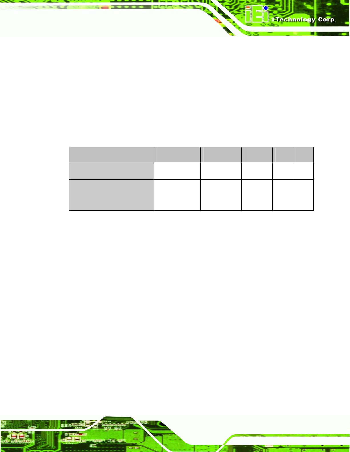
1.1.1 ROCKY-3786EV Model Variations
The ROCKY-3786EV has two model variations shown in Table 1-1.
Model Name CPU Ethernet USB VGA CFII
MODEL NAME
ROCKY-3786EV-RS-R41
ROCKY-3786EVGU2-RS-R41
Table 1-1: ROCKY-3786EV Model Variations
Socket 370 base 10/100Mbps USB 1.1 Yes Yes
Socket 370 base 10/100Mbps +
GbE
USB 1.1 +
USB 2.0
1.1.2 ROCKY-3786EV CPU Board Applications
The ROCKY-3786EV CPU board has been designed for use in industrial applications
where board expansion is critical and operational reliability is essential.
1.1.3 ROCKY-3786EV CPU Board Benefits
Some of the ROCKY-3786EV CPU board benefits include,
providing on-chip VGA which supports up to 1600x1200 resolution.
operating reliably in harsh industrial environments with ambient temperatures
Yes Yes
as high as 60°C
providing parallel port and IDE interface which are compatible with IBM PC/AT
architecture
1.1.4 ROCKY -3786EV CPU Board Features
Some of the ROCKY-3786EV CPU board features are listed below:
Page 13
Page 13
Page 14
Complies with PICMG 1.0
Complies with RoHS
Supports up to 133 MHz front side bus (FSB)
Supports up to 512 MB SDRAM memory module
Supports two SATA channels with transfer rates up to 150MB/s
Optional high performance gigabit Ethernet (GbE) controller
Optional USB 2.0 connectors
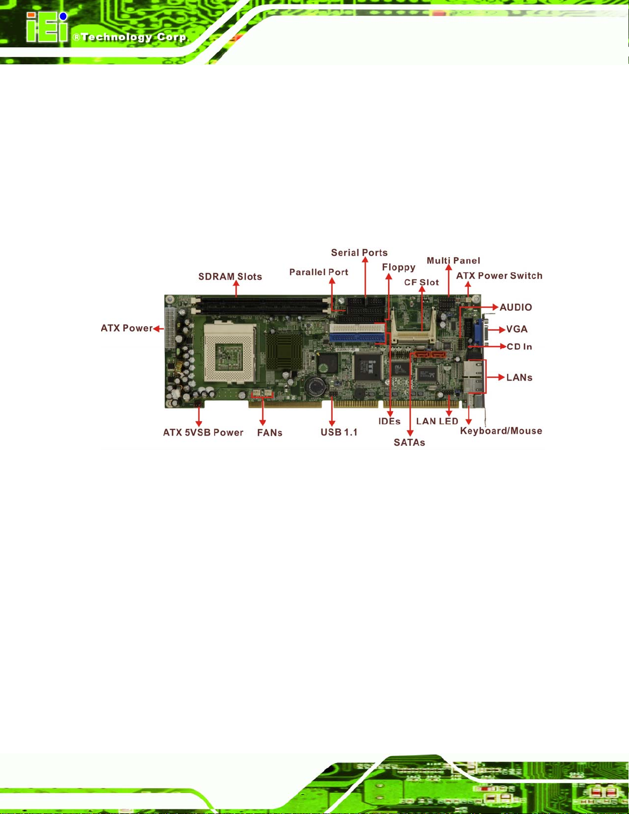
1.2 ROCKY-3786EV CPU Board Overview
ROCKY-3786EV CPU Card
Figure 1-1 ROCKY-3786EV CPU Board Overview
1.2.1 ROCKY-3786EV CPU Board Connectors
The ROCKY-3786EV CPU board has the following connectors onboard:
1 x ATX power connector
1 x ATX power 5VSB and PSON connector
1 x ATX power switch connector
1 x Audio connector
1 x CD-in connector
1 x Compact Flash slot
2 x CPU fan connectors
2 x SDRAM slots
1 x Floppy disk drive connector
2 x IDE device connectors
Page 14
Page 14
Page 15
ROCKY-3786EV CPU Card
1 x IrDA connector
1 x Keyboard/Mouse connector
1 x LAN LED connector
1 x Multi panel connector
1 x Parallel port connector
2 x SATA connectors
2 x Serial port connectors
2 x USB 1.1 connectors
4 x USB 2.0 connectors (optional)
1 x VGA connector
The ROCKY-3786EV CPU board has the following connectors on the board rear panel:
1 x Audio Line Out connector
2 x RJ-45 Ethernet connectors
1 x Keyboard/Mouse connector
MODEL NAME
1 x VGA connector
The location of these connectors on the CPU Card can be seen in
connectors are fully described in Chapter
2.
Figure 3-21. These
NOTE:
There are no configuration jumpers or connectors on the soldering side.
1.2.2 Technical Specifications
ROCKY-3786EV CPU board technical specifications are listed in Table 1-2. Detailed
descriptions of each specification can be found in Chapter
SPECIFICATION
CPUs Supported
®
Pentium® III, Celeron®, or VIA C3
Intel
2.
Chipsets
I/O Controller
Northbridge: Intel
Southbridge: Intel® ICH2
IT8712
®
815E
Page 15
Page 15
Page 16
ROCKY-3786EV CPU Card
Graphics Support
Memory
PCI Bus Interface
Serial A TA (SATA)
HDD Interface
Floppy Disk Drive (FDD)
USB Interfaces
Serial Ports
On Chip Intel® 815E
Two PC 100/133 SDRAM memory modules (Max.
512MB)
33MHz, Revision 2.2
Two SATA connectors support RAID 0, 1
(VIA VT6421A Serial RAID controller)
Two IDE channels supports four Ultra ATA 33/66/100
devices
Supports FDD
Two USB 1.1 connectors supported
Four USB 2.0 connectors supported (optional)
Two high-speed 16C550 compatible UARTs ports
Hardware Monitoring
Power Management
Infrared Support
Ethernet
BIOS
Physical Dimensions
Operating Temperature
Audio
Cooling fan, temperature and system voltages
Supports Advanced Configuration and Power Interface
(ACPI) Specifications Revision 2.0
Supports Serial Infrared (SIR) and Amplitude Shift
Keyed IR (ASKIR) interface
®
82562ET 10/100Mbps or
Intel
®
Intel
82541 GbE
Award BIOS
380mm x 125mm (width x length)
Minimum: 0ºC (32°F)
Maximum: 60°C (140°F)
Audio Codec ’97 (AC’97) version 2.3 Realtek ALC655
Page 16
Page 16
Table 1-2: Technical Specifications
Page 17
ROCKY-3786EV CPU Card
MODEL NAME
Chapter
2
2 Detailed Specifications
Page 17
Page 17
Page 18
2.1 CPU Support
The ROCKY-3786EV CPU card has socket 370 and supports the following CPUs:
Intel® Pentium® III (FC-PGA) processor, up to 1.4GHz
Intel® Celeron® processor, 700MHz – 1.2GHz
VIA C3 processor, 733MHz or above
2.1.1 Pentium® III
The Intel® Pentium® III CPU comes with the following features:
Available in 1.10 GHz, 1 GHz, 900, 850, 800, 750, 700, 650, 600E, 550E, and
500E MHz for a 100 MHz system bus
System bus frequency at 100 MHz and 133 MHz (“E” denotes support for
Advanced Transfer Cache and Advanced system buffering; “B” denotes
support for a 133 MHz system bus where both bus frequencies are available
ROCKY-3786EV CPU Card
for order per each given core frequency
Available in versions that incorporate 256-KB Advanced Transfer Cache
(on-die, full speed Level 2 (L2) cache with Error Correcting Code (ECC))
Dual Independent Bus (DIB) architecture: Separate dedicated external
System Bus and dedicated internal high-speed cache bus
Internet Streaming SIMD Extensions for enhanced video, sound and 3D
performance
Binary compatible with applications running on previous members of the Intel
microprocessor line
Dynamic execution micro architecture
Intel Processor Serial Number
Power Management capabilities
o System Management mode
o Multiple low-power states
Optimized for 32-bit applications running on advanced 32-bit operating
systems
Flip Chip Pin Grid Array (FC-PGA/FC-PGA2) packaging technology;
Page 18
Page 18
FC-PGA/FC-PGA2 processors deliver high performance with improved
handling protection and socketability
Page 19

ROCKY-3786EV CPU Card
Integrated high performance 16-KB instruction and 16-KB data, nonblocking,
level one cache
256-KB Integrated Full Speed level two cache allows for low latency on
read/store operations
Double Quad Word Wide (256 bit) cache data bus provides extremely high
throughput on read/store operations.
8-way cache associativity provides improved cache hit rate on reads/store
operations.
Error-correcting code for System Bus data
Enables systems which are scaleable for up to two processors
2.1.2 Celeron®
The Intel® Celeron® CPU comes with the following features:
300, 366, 433, 566, 733, 850 MHz, and 1.2 GHz processor speeds
MODEL NAME
32K L1 cache (16K code and 16K data)
128K integrated L2 cache; 256K for 1.2 GHz
High performance floating-point unit
Intel® MMX™ technology
66 MHz Processor Side Bus (PSB) for 300 - 733 MHz processor speeds, and
100 MHz PSB for 850 MHz and 1.2 GHz
Compatible with 370 pin Socket specifications
Compatible with Intel® 815, 815E, 810 and Intel® 440BX chipsets (except 1.2
GHz)
1.2 GHz supported by Intel® 815/E, 810E2 chipsets
Flip-Chip Pin Grid Array (FC-PGA2) package (for 1.2 GHz)
Flip-Chip Pin Grid Array (FC-PGA) package (566, 733 and 850 MHz)
Plastic Pin Grid Array (PPGA) package (300, 366, and 433 MHz)
Built-in Self Test (BIST)
2.1.3 VIA® C3
The VIA® C3 CPU comes with the following features:
Padlock Advanced Cryptography Engine (available in Stepping 8 and higher).
Padlock Random Number Generator (available in Stepping 3 and higher).
Page 19
Page 19
Page 20

Plug-compatible with Socket 370 processors in terms of bus protocol,
electrical interface, and physical package
Software-compatible with thousands of x86 software applications available
MMX-compatible instructions
SSE-compatible instructions
Two large (64-KB each, 4-way) on-chip caches (2-way in Stepping 8 and
higher)
64-KB Level 2 victim cache (16-way)
Two large TLBs (128 entries each, 8-way)
Branch Target Address Cache with 1k entries each identifying 2 branches
Unique and sophisticated branch prediction mechanisms
Bus speeds up to 133 MHz
Extremely low power dissipation
Very small die-52 mm2 in TSMC 0.13μ technology (47 mm2 for Stepping 8
and higher)
ROCKY-3786EV CPU Card
2.2 Onboard Chipsets
2.2.1 Northbridge and Southbridge Chipsets
The following chipsets are preinstalled on the board:
Northbridge: Intel® 815E
Southbridge: Intel® ICH2
The following two sections (Section
the Intel® 815E and the Intel® ICH2 chipsets. For more information on these two chipsets
please refer to the Intel website.
2.2.2 Intel® 815E Northbridge Chipset
The Intel® 815E northbridge chipset comes with the following features:
Flexible processor support ranging from the Intel Celeron processor - Ultra
Low Power at 300MHz to the Pentium III processor - Low Power at 700 MHz
2.2.2 and Section 2.2.3) list some of the features of
Page 20
Page 20
and the Celeron processor at 566 MHz to the Pentium III processor with 512K
cache at 1.26 GHz and beyond with support for 66, 100, or 133 MHz
Processor Side Bus (PSB) speeds
Page 21

ROCKY-3786EV CPU Card
Increased I/O bus bandwidth through the use of Intel Hub Architecture which
allows better concurrency for next-generation embedded computing
applications
Support for 100 and 133 MHz SDRAM enabling cost effective high volume
memory
512 MB maximum memory
Low power sleep mode for energy savings
Dual (815) or Quad (815E) USB ports
Support for ATA/66 (815) or ATA/100 (815E)
Integrated AC '97 Controller for cost effective audio and modem solutions
Support (815E)
Alert on LAN 1.0
Intel 3D integrated graphics with Direct AGP expandability for vivid 2D and 3D
graphics
AGP4X upgradeable for increased graphics bandwidth allowing the highest
MODEL NAME
possible graphics performance
Add-in Graphics Performance Accelerator (GPA) card to provide up to a 30%
boost for better 2D and 3D graphics performance over similar systems without
a GPA card
AC '97 Controller for better audio quality
Soft DVD MPEG-2 playback with HW motion compensation for life-like audio
and video
2.2.3 Intel® ICH2 Southbridge Chipset
The Intel® ICH2 southbridge chipset comes with the following features:
PCI Bus I/F
o Supports PCI at 33 MHz
o Supports PCI Rev 2.2 Specification
o 133 MByte/sec maximum throughput
o Supports up to 6 master devices on PCI
o One PCI REQ/GNT pair can be given higher arbitration priority (intended
for external 1394 host controller)
Integrated LAN Controller
o WfM 2.0 Compliant
o Interface to discrete LAN Connect component
Page 21
Page 21
Page 22

ROCKY-3786EV CPU Card
o 10/100 Mbit/sec Ethernet support
o 1 Mbit/sec HomePNA* support
Integrated IDE Controller
o Independent timing of up to 4 drives
o Ultra ATA/100/66/33, BMIDE and PIO modes
o Read transfers up to 100MB/s, Writes to 89 MB/s
o Separate IDE connections for Primary and Secondary cables
o Implements Write Ping-Pong Buffer for faster write performance
USB
o 2 UHCI Host Controllers with a total of 4 ports
o USB 1.1 compliant
o Supports wake-up from sleeping states S1–S4
o Supports legacy Keyboard/Mouse software
AC'97 Link for Audio and Telephony CODECs
o AC’97 2.1 compliant
o Independent bus master logic for 5 channels (PCM In/Out, Mic Input,
Modem In/Out)
o Separate independent PCI functions for Audio and Modem
o Support for up to six channels of PCM audio output (full AC3 decode)
o Supports wake-up events
Interrupt Controller
o Support up to 8 PCI interrupt pins
o Supports PCI 2.2 Message-Based Interrupts
o Two cascaded 82C59
o Integrated I/O APIC capability
o 15 interrupts supported in 8259 mode, 24 supported in I/O APIC mode
o Supports Serial Interrupt Protocol
o Supports Front-Side Bus interrupt delivery
1.8 V operation with 3.3 V I/O
o 5V tolerant buffers on IDE, PCI, USB Overcurrent and Legacy signals
GPIO
o TTL, Open-Drain, Inversion
Page 22
Page 22
Timers Based on 82C54
o System timer, Refresh request, Speaker tone output
Power Management Logic
o ACPI 1.0 compliant
Page 23
ROCKY-3786EV CPU Card
o ACPI Power Management Timer
o PCI PME# support
o SMI# generation
o All registers readable/restorable for proper resume from 0V suspend
states
o Support for APM-based legacy power management for non-ACPI
implementations
External Glue Integration
o Integrated Pull-up, Pull-down and Series Termination resistors on IDE
and processor interface
Enhanced Hub I/F buffers improve routing flexibility (Not available with all
Memory Controller Hubs)
Firmware Hub (FWH) I/F supports BIOS memory size up to 8 MBs
Low Pin count (LPC) I/F
o Allows connection of legacy ISA and X-Bus devices such as Super I/O
MODEL NAME
o Supports two Master/DMA devices.
Enhanced DMA Controller
o Two cascaded 8237 DMA controllers
o PCI DMA: Supports PC/PCI Includes two PC/PCI REQ#/GNT# pairs
o Supports LPC DMA
o Supports DMA Collection Buffer to provide Type-F DMA performance for
all DMA channels
Real-Time Clock
o 256-byte battery-backed CMOS RAM
o Hardware implementation to indicate century rollover
System TCO Reduction Circuits
o Timers to generate SMI# and Reset upon detection of system hang
o Timers to detect improper processor reset
o Integrated processor frequency strap logic
SM Bus
o Host interface allows processor to communicate via SM Bus
o Slave interface allows an external Microcontroller to access system
resources
o Compatible with most 2-Wire components that are also I2C compatible
Supports ISA bus via external PCI-ISA Bridge
360-pin EBGA package
Page 23
Page 23
Page 24
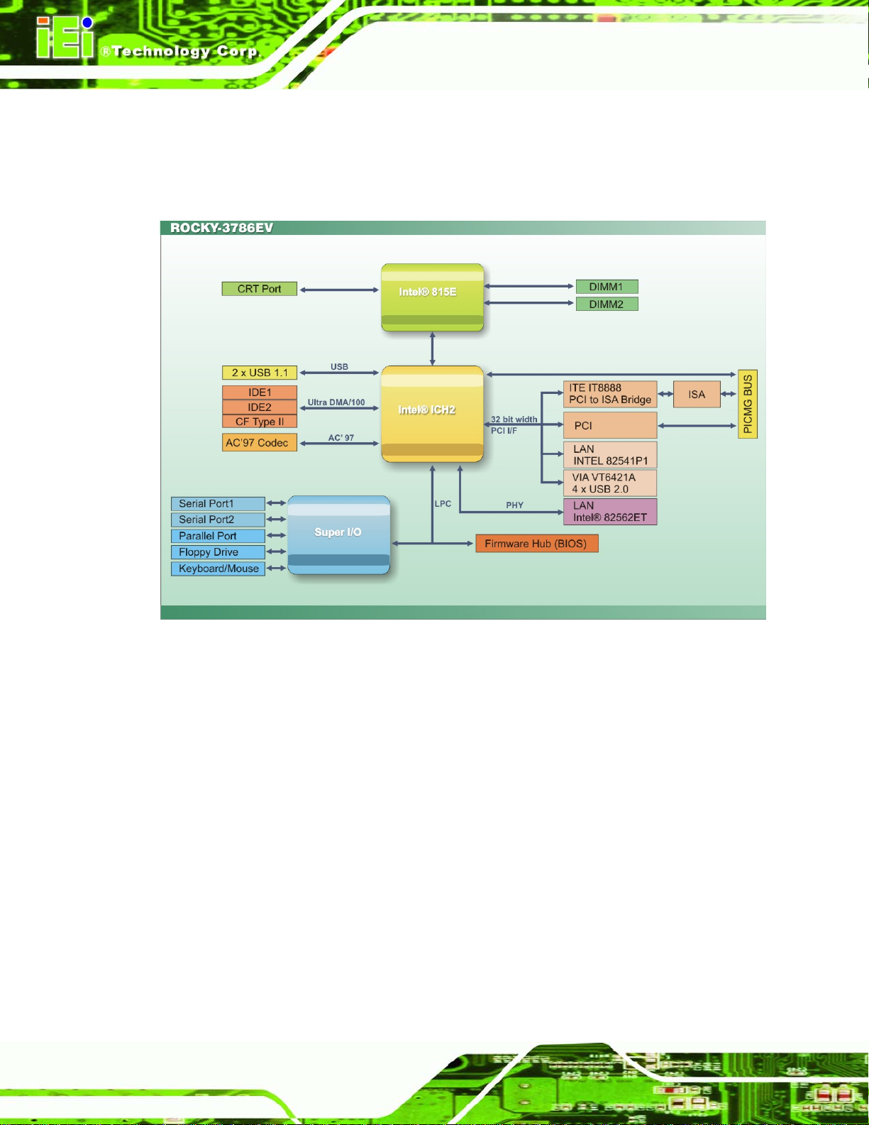
2.3 Data Flow
Figure 2-1 shows the data flow between the two onboard chipsets and other components
installed on the CPU board and described in the following sections of this chapter.
ROCKY-3786EV CPU Card
Figure 2-1: Data Flow Block Diagram
2.4 Graphics Support
The graphics features listed below are all integrated on the Intel 815E northbridge chipset.
Integrated Graphics Controller Multiplexed with AGP Controller
o 3D Hyper Pipelined Architecture
o Full 2D H/W Acceleration
o Motion Video Acceleration
o Supports 133 MHz System Memory while running in non-CPC mode
3D Graphics Visual Enhancements
o Flat & Gouraud Shading
o Mip Maps with Trilinear and Anisotropic Filtering
o Full Color Specular
Page 24
Page 24
Page 25

ROCKY-3786EV CPU Card
o Fogging Atmospheric Effects
o Z Buffering
o 3D Pipe 2D Clipping
o Backface Culling
Digital Video Output
o 85 MHz Flat Panel Monitor/Digital CRT Interface Or Digital Video Output
for use with a external TV encoder
Display
o Integrated 24-bit 230 MHz RAMDAC
o Gamma Corrected Video
o DDC2B Compliant
2D Graphics
o Up to 1600x1200 in 8-bit Color at 85 Hz Refresh
o Hardware Accelerated Functions
Arithmetic Stretch Blitter Video
MODEL NAME
o H/W Motion Compensation Assistance for S/W MPEG2 Decode
o Software DVD at 30 fps
o Digital Video Out Port
o NTSC and PAL TV Out Support
o H/W Overlay Engine with Bilinear Filtering
o Independent gamma correction, saturation, brightness & contrast for
overlay
2.5 Memory Support
The ROCKY-3786EV CPU card has two 168-pin memory module (DIMM) sockets and
support PC100/133 SDRAM with the following specifications:
Maximum RAM: 512MB
DIMM Transfer Rates: 100MHz, 133MHz
2.6 PCI Bus Interface Support
The PCI bus on the ROCKY-3786EV CPU Board has the following features:
33MHz Revision 2.2 is implemented
Up to six master devices are supported
Maximum throughput: 133MB/sec
Page 25
Page 25
Page 26

One PCI REQ/GNT pair can be given higher arbitration priority (intended for
external 1394 host controller)
2.7 10/100/1000Mbps Ethernet
The onboard Intel 82562ET controller (for ROCKY-3786EV) provides 10/100 Base-T
Internet connectivity to the system. The Intel 82562ET controller features are below.
IEEE 802.3 10BASE-T/100BASE-TX compliant physical layer interface
IEEE 802.3u Auto-Negotiation support
Digital Adaptive Equalization control
Link status interrupt capability
XOR Tree mode support for board testing
3-port LED support (speed, link and activity)
10BASE-T auto-polarity correction
Diagnostic loopback mode
ROCKY-3786EV CPU Card
1:1 transmit transformer ratio support
Low power (less than 300 mW in active transmit mode)
Reduced power in “unplugged mode” (less than 50 mW)
Automatic detection of “unplugged mode”
3.3 V device
48-pin Shrink Small Outline Package
Platform LAN connect interface support
The onboard Intel 82541PI controller (for ROCKY-3786EVGU2) provides GbE Ethernet
interface. The Intel 82541PI controller features are below.
IEEE 802.3 10BASE-T compliant physical layer interface
IEEE 802.3u Auto-Negotiation and 100BASE-TX support
Power Save mode switches link speed from 1000Mb/s down to 10 or 100Mb/s
PCI clock suspension for low-power mobile design
Programmable host memory receive buffers (256B to 16KB)
TCP segmentation (LSO), TCP and UDP checksum off-loading
Page 26
Page 26
Compliance with PCI Power Management v1.1/ACPI v2.0
Automatic link speed switching from 1000Mb/s down to 10 or 100Mb/s in
standby
Page 27

ROCKY-3786EV CPU Card
2.8 Drive Interfaces
The ROCKY-3786EV can support the following drive interfaces.
2 x SATA drives
2 x IDE devices
1 x FDD
1 x Compact Flash (CF) Card
2.8.1 SATA Drives
The ROCKY-3786EV CPU Board supports two first generation SATA drives with transfer
rates up to 150MB/s via VIA VT6421A Serial RAID controller. The two SATA connectors
also support RAID 0, 1.
2.8.2 IDE HDD Interfaces
MODEL NAME
The ROCKY-3786EV southbridge chipset IDE controller supports up to four HDDs with
the following specifications:
Supports PIO IDE transfers up to 16MB/s
Supports the following Ultra ATA devices:
o Ultra ATA/33, with data transfer rates up to 33MB/s
o Ultra ATA/66, with data transfer rates up to 66MB/s
o Ultra ATA/100, with data transfer rates up to 100MB/s
2.8.3 Floppy Disk Drive (FDD)
The ROCKY-3786EV CPU Board supports a single FDD. The following FDD formats are
compatible with the board.
5.25”: 360KB and 1.2MB
3.5”: 720KB, 1.44MB and 2.88MB
2.8.4 Compact Flash Support
Standard CF-II cards can be inserted into the compact flash slot on the solder
side of the ROCKY-3786EV.
Page 27
Page 27
Page 28

ROCKY-3786EV CPU Card
2.9 Serial Ports
The ROCKY-3786EV CPU board has two high-speed UART serial ports, configured as
CN2 and CN8. The serial ports have the following specifications.
16C550 UART with 16-byte FIFO buffer
115.2Kbps transmission rate
2.10 Real Time Clock
256-byte battery backed CMOS RAM
2.11 Infrared Data Association (IrDA) Interface
The ROCKY-3786EV CPU Board IrDA supports the following interfaces.
Serial Infrared (SIR)
Shift Keyed Infrared (ASKIR)
If an IrDA port is need, COM2 must be configured as either SIR or ASKIR mode in the
BIOS under Super IO devices.
2.12 USB Interfaces
The ROCKY-3786EV CPU board has two internal USB 1.1 interfaces. The
ROCKY-3786EVGU2 has additional four internal USB 2.0 interfaces.
2.13 BIOS
The ROCKY-3786EV CPU Board uses a licensed copy of Phoenix AwardBIOS. Flash
BIOS features used are listed below:
SMIBIOS (DMI) compliant
Console redirection function support
PXE (Pre-Boot Execution Environment) support
USB booting support
2.14 Operating Temperature and Temperature Control
The maximum and minimum operating temperatures for the ROCKY-3786EV CPU Board
are listed below.
Page 28
Page 28
Page 29

ROCKY-3786EV CPU Card
Minimum Operating Temperature: 0ºC (32°F)
Maximum Operating Temperature: 60°C (140°F)
A cooling fan and heat sink must be installed on the CPU. Thermal paste must be
smeared on the lower side of the heat sink before it is mounted on the CPU. Heat sinks
are also mounted on the northbridge and southbridge chipsets to ensure the operating
temperature of these chips remain low.
2.15 Audio Codec
The ROCKY-3786EV has an integrated REALTEK ALC655 CODEC. The ALC655
CODEC is a 16-bit, full-duplex AC'97 Rev. 2.3 compatible six-channel audio CODEC
designed for PC multimedia systems, including host/soft audio and AMR/CNR-based
designs. Some of the features of the codec are listed below.
Meets performance requirements for audio on PC99/2001 systems
MODEL NAME
Meets Microsoft WHQL/WLP 2.0 audio requirements
16-bit Stereo full-duplex CODEC with 48KHz sampling rate
Compliant with AC'97 Rev 2.3 specifications
Front-Out, Surround-Out, MIC-In and LINE-In Jack Sensing
14.318MHz -> 24.576MHz PLL to eliminate crystal
12.288MHz BITCLK input
Integrated PCBEEP generator to save buzzer
Interrupt capability
Three analog line-level stereo inputs with 5-bit volume control, LINE_IN, CD,
AUX
High-quality differential CD input
Two analog line-level mono inputs: PCBEEP, PHONE-IN
Two software selectable MIC inputs
Dedicated Front-MIC input for front panel applications (software selectable)
Boost preamplifier for MIC input
LINE input shared with surround output; MIC input shared with Center and
LFE output
Built-in 50mW/20ohm amplifier for both Front-out and Surround-Out
External Amplifier Power Down (EAPD) capability
Power management and enhanced power saving features
Supports Power-Off CD function
Page 29
Page 29
Page 30
Adjustable VREFOUT control
Supports 48KHz S/PDIF output, complying with AC'97 Rev 2.3 specifications
Supports 32K/44.1K/48KHz S/PDIF input
Power support: Digital: 3.3V; Analog: 3.3V/5V
Standard 48-pin LQFP package
EAX™ 1.0 & 2.0 compatible
Direct Sound 3D™ compatible
A3D™ compatible
I3DL2 compatible
HRTF 3D positional audio
10-band software equalizer
Voice cancellation and key shifting in Karaoke mode
2.16 Power Consumption
Table 2-1 shows the power consumption parameters for the ROCKY-3786EV CPU board
ROCKY-3786EV CPU Card
when a Pentium® III processor with a clock speed of 1GHz is running with a 256MB DDR
module.
Voltage Current
+5V 7.6A
+12V 0.23A
Table 2-1: Power Consumption
2.17 Packaged Contents and Optional Accessory Items
2.17.1 Package Contents
The ROCKY-3786EV is shipped with the following components.
1 x ROCKY-3786EV single board computer
1 x ATA66/100 flat cable
Page 30
Page 30
2 x SATA cable
1 x SATA power cable
1 x RS232 cable
1 x USB cable
Page 31

ROCKY-3786EV CPU Card
1 x Keyboard/ PS2 mouse Y cable
1 x Mini jumper pack
1 x QIG (quick installation guide)
1 x Utility CD
2.17.2 Optional Accessory Items
The items shown in the list below are optional accessory items purchased separately.
FDD cable
LPT cable
CPU cooler
MODEL NAME
Page 31
Page 31
Page 32

ROCKY-3786EV CPU Card
Chapter
3
3 Connectors and Jumpers
Page 32
Page 32
Page 33

ROCKY-3786EV CPU Card
3.1 Peripheral Interface Connectors
The locations of the peripheral interface connectors are shown in Section 3.1.1. A
MODEL NAME
complete list of all the peripheral interface connectors can be seen in Section
3.1.1 ROCKY -3786EV CPU Board Layout
Figure 3-1 shows the onboard peripheral connectors, backplane peripheral connectors
and onboard jumpers.
3.1.2.
Figure 3-1: Connector and Jumper Locations
3.1.2 Peripheral Interface Connectors
Table 3-1 shows a list of the peripheral interface connectors on the ROCKY-3786EV CPU
board. Detailed descriptions of these connectors can be found in Section
Connectors Type Label
ATX power connector 20-pin header CN21
ATX power 5VSB and PSON connector 3-pin header CN20
ATX power switch connector 2-pin header CN5
Audio connector 12-pin header CN28
CD In connector 4-pin header CN27
Compact Flash (CF) slot 50-pin header CN25
3.2.
Page 33
Page 33
Page 34

CPU fan connector (1) 3-pin header FAN2
CPU fan connector (2) 3-pin header FAN3
CRT connector 10-pin header CN26
SDRAM slot (1) 168-pin slot DIMM0
SDRAM slot (2) 168-pin slot DIMM1
FDD connector 34-pin header CN3
IDE Interface connector (Primary) 40-pin header CN1
IDE Interface connector (Secondary) 40-pin header CN7
IrDA connector 5-pin header CN4
Keyboard connector 5-pin header CN22
ROCKY-3786EV CPU Card
LAN LED connector 8-pin header CN12
Multi Panel connector 14-pin header CN24
Parallel port connector 26-pin header CN9
SATA drive port (1) SATA disk drive port CN29
SATA drive port (2) SATA disk drive port CN30
Serial port connector 10-pin header CN2
Serial port connector 10-pin header CN8
USB 1.1 connector 8-pin header CN6
USB 2.0 connector (optional) 8-pin header USB1
USB 2.0 connector (optional) 8-pin header USB2
Table 3-1: Peripheral Interface Connectors
Page 34
Page 34
Page 35

ROCKY-3786EV CPU Card
3.1.3 Rear Panel Connectors
Table 3-2 lists the rear panel connectors on the ROCKY-3786EV CPU card. Detailed
MODEL NAME
descriptions of these connectors can be found in Section
Connectors Type Label
Audio Line Out connector LINE OUT CN16
10/100Mbps Ethernet connector RJ-45 LAN1
Optional 1Gb Ethernet connector RJ-45 LAN2
Keyboard/Mouse connector PS/2 CN23
VGA connector 15-pin VGA connector CN11
Table 3-2: Peripheral Interface Connectors
3.3.
3.1.4 Onboard Jumpers
Table 3-3 lists the onboard jumpers. Detailed descriptions of these jumpers can be found
in Section
3.4.
Jumpers Type Label
Clear CMOS Setup 3-pin header JP1
BIOS protection setting 3-pin header JP2
Keyboard power selection 3-pin header JP4
CF mode selection 2-pin header JP3
Table 3-3: Onboard Jumpers
Page 35
Page 35
Page 36

3.2 Internal Peripheral Connectors
Internal peripheral connectors are found on the CPU card and are only accessible when
the CPU board is outside of the chassis. This section has complete descriptions of all the
internal, peripheral connectors on the ROCKY-3786EV CPU board.
3.2.1 ATX Power Connector
CN Label: CN21
CN Type: 20-pin header (2x10)
ROCKY-3786EV CPU Card
CN Location: See
CN Pinouts: See
The
ROCKY-3786EV can work without backplane, while attaching external power to this
Figure 3-2
Table 3-4
ATX power connector. This connector supports the ATX power supply.
PIN NO. DESCRIPTION PIN NO. DESCRIPTION
11 3.3V 1 3.3V
12 -12V 2 3.3V
13 GND 3 GND
14 PSON# 4 +5V
15 GND 5 GND
16 GND 6 +5V
17 GND 7 GND
18 -5V 8 Power good
19 +5V 9 +5VSB
20 +5V 10 +12V
Table 3-4: ATX Power Connector Pinouts
Page 36
Page 36
Page 37

ROCKY-3786EV CPU Card
Figure 3-2: ATX Power Connector Location
3.2.2 ATX Power 5VSB and PSON connector
CN Label: CN20
MODEL NAME
CN Type: 3-pin header
CN Location: See
CN Pinouts: See
Figure 3-3
Table 3-5
PIN NO. DESCRIPTION
1
2 PSON#
3 GND
Table 3-5: ATX Power 5VSB and PSON Connector Pinouts
+5VSB
Page 37
Page 37
Page 38

Figure 3-3: ATX Power 5VSB and PSON Connector Location
3.2.3 ATX Power Switch Connector
ROCKY-3786EV CPU Card
CN Label: CN5
CN Type: 2-pin header
CN Location: See
CN Pinouts: See
The ATX power switch connector supports ATX power switch and enables power on/off
from the chassis.
PIN NO. DESCRIPTION
1 PWR_BUTTON+
2 PWR_BUTTON-
Table 3-6: ATX Power Switch Connector Pinouts
Figure 3-4
Table 3-6
Page 38
Page 38
Page 39

ROCKY-3786EV CPU Card
Figure 3-4: ATX Power Switch Connector Location
3.2.4 Audio Connector
MODEL NAME
CN Label: CN28
CN Type: 12-pin header (2x6)
CN Location: See
CN Pinouts: See
Figure 3-5
Table 3-7
The ROCKY-3786EV has a built-in AC ’97 AUDIO CODEC connector directly connected
to the SPEAKER-OUT, MIC-IN, LINE-IN and LINE-OUT.
PIN NO. DESCRIPTION
1 LEFT SPEAKER OUT SIGNAL (WITH OP MPLIFIER)
2 RIGHT SPEAKER OUT SIGNAL (WITH OP AMPLIFIER)
3 GROUND (FOR SPK CONNECTOR)
4 GROUND (FOR LINE OUT CONNECTOR)
5 LEFT LINE OUT SIGNAL
6 RIGHT LINE OUT SIGNAL
7 LEFT LINE IN SIGNAL
8 RIGHT LINE IN SIGNAL
9 GROUND (FOR LINE IN CONNECTOR)
Page 39
Page 39
Page 40

10 GROUND (NO USE)
11 MIC IN
12 GROUND (FOR MIC IN CONNECTOR)
Table 3-7: Audio Connector Pinouts
ROCKY-3786EV CPU Card
Figure 3-5: Audio connector Location
3.2.5 CD In Connector
CN Label: CN27
CN Type: 4-pin header
CN Location: See
CN Pinouts: See
This 4-pin header connects to audio sources such as CD/DVD-ROM optical drives.
PIN NO. DESCRIPTION
1 CD Left
2 GND
3 GND
Figure 3-6
Table 3-8
Page 40
Page 40
Page 41

ROCKY-3786EV CPU Card
4 CD Right
Table 3-8: CD In Connector Pinouts
Figure 3-6: CD In Connector Location
MODEL NAME
3.2.6 Compact Flash Socket
CN Label: CN25
CN Type: 50-pin header (2x25)
CN Location: See
CN Pinouts: See
A compact flash memory module is inserted to the Compact Flash connector (CF1).
Jumper 2 (JP2) configures the compact flash drive as either a slave or master device.
PIN NO. DESCRIPTION PIN NO. DESCRIPTION
1 GROUND 26 CARD DETECT1
2 D3 27 D11
3 D4 28 D12
4 D5 29 D13
Figure 3-7
Table 3-9
5 D6 30 D14
6 D7 31 D15
7 CS1# 32 CS3#
8 N/C 33 N/C
Page 41
Page 41
Page 42

9 GROUND 34 IOR#
10 N/C 35 IOW#
11 N/C 36 OBLIGATORY TO PULL HIGH
12 N/C 37 IRQ15
13 VCC 38 VCC
14 N/C 39 MASTER/SLAVE
15 N/C 40 N/C
16 N/C 41 RESET#
17 N/C 42 IORDY
18 A2 43 N/C
19 A1 44 OBLIGATORY TO PULL HIGH
20 A0 45 ACTIVE#
21 D0 46 PDIAG#
22 D1 47 D8
ROCKY-3786EV CPU Card
23 D2 48 D9
24 N/C 49 D10
25 CARD DETECT2 50 GROUND
Table 3-9: CFII Socket Pinouts
Figure 3-7: CFII Socket Location
Page 42
Page 42
Page 43

ROCKY-3786EV CPU Card
3.2.7 CPU Fan Connector
CN Label: FAN2 and FAN3
CN Type: 3-pin header
MODEL NAME
CN Location: See
CN Pinouts: See
The CPU fan connector provides a 12V/500mA to the cooling fan. The connector has a
"rotation" pin to get rotation signals from the fan and notify the system so the system BIOS
can recognize the fan speed. Please note that only certain fans can issue the rotation
signals.
PIN NO. DESCRIPTION
1 GND
2 +12V
3 Sensor
Table 3-10 CPU Fan Connector Pinouts
Figure 3-8
Table 3-10
Figure 3-8 CPU Fan Connector Locations
Page 43
Page 43
Page 44

3.2.8 CRT Connector
CN Label: CN26
CN Type: 10-pin header (2x5)
ROCKY-3786EV CPU Card
CN Location: See
CN Pinouts: See
Figure 3-10
Table 3-12
PIN NO. DESCRIPTION PIN NO. DESCRIPTION
1 RED 2 DDCCLK
3 GREEN 4 DDC DAT
5 BLUE 6 GROUND
7 HSYNC 8 GROUND
9 VSYNC 10 GROUND
Table 3-11: CRT Connector Pinouts
Figure 3-9: CRT Connector Location
3.2.9 FDD Connector
CN Label: CN3
CN Type: 34-pin header (2x17)
CN Location: See
CN Pinouts: See
Page 44
Page 44
Figure 3-10
Table 3-12
Page 45

ROCKY-3786EV CPU Card
The ROCKY-3786EV is shipped with a 34-pin daisy-chain drive connector cable. This
cable can be connected to the FDD connector.
PIN NO. DESCRIPTION PIN NO. DESCRIPTION
1 GROUND 2 REDUCE WRITE
3 GROUND 4 N/C
5 GROUND 6 N/C
7 GROUND 8 INDEX#
9 GROUND 10 MOTOR ENABLE A#
11 GROUND 12 DRIVE SELECT B#
13 GROUND 14 DRIVE SELECT A#
15 GROUND 16 MOTOR ENABLE B#
17 GROUND 18 DIRECTION#
19 GROUND 20 STEP#
MODEL NAME
21 GROUND 22 WRITE DATA#
23 GROUND 24 WRITE GATE#
25 GROUND 26 TRACK 0#
27 GROUND 28 WRITE PROTECT#
29 N/C 30 READ DATA#
31 GROUND 32 SIDE 1 SELECT#
33 N/C 34 DISK CHANGE#
Table 3-12: FDD Connector Pinouts
Page 45
Page 45
Page 46

Figure 3-10: FDD Connector Location
3.2.10 IDE Interface Connectors
ROCKY-3786EV CPU Card
CN Label: CN1 (primary) and CN7 (secondary)
CN Type: 40-pin header (2x20)
CN Location: See
CN Pinouts: See
Two IDE connectors provide connectivity for four IDE devices.
Figure 3-11
Table 3-13
Page 46
Page 46
Page 47

ROCKY-3786EV CPU Card
PIN NO. DESCRIPTION PIN NO. DESCRIPTION
MODEL NAME
1
3
5
7
9
11
13
15
17
19
21
23
25
27
29
31
RESET#
DATA 7
DATA 6
DATA 5
DATA 4
DATA 3
DATA 2
DATA 1
DATA 0
GROUND
N/C
IOW#
IOR#
N/C
N/C
INTERRUPT
2 GROUND
4
6
8
10
12
14
16
18
20
22
24
26
28
30
32
DATA 8
DATA 9
DATA 10
DATA 11
DATA 12
DATA 13
DATA 14
DATA 15
N/C
GROUND
GROUND
GROUND
BALE - DEFAULT
GROUND - DEFAULT
IOCS16#-DEFAULT
33
35
37
39
SA1
SA0
HDC CS0#
HDD ACTIVE#
34
36
38
40
N/C
SA2
HDC CS1#
GROUND
Table 3-13: IDE Interface Connector Pinouts
Page 47
Page 47
Page 48

ROCKY-3786EV CPU Card
Figure 3-11: IDE Interface Connector Locations
3.2.11 IrDA Connector
CN Label: CN4
CN Type: 5-pin header
CN Location: See
CN Pinouts: See
The integrated IrDA connector supports both the SIR and ASKIR infrared protocols.
PIN NO. DESCRIPTION
1 VCC5V
2 N/C
3 IR-RX
4 Ground
5 IR-TX
Figure 3-12
Table 3-14
Page 48
Page 48
Table 3-14: IrDA Connector Pinouts
Page 49

ROCKY-3786EV CPU Card
Figure 3-12: IrDA Connector Location
3.2.12 Keyboard Connector
MODEL NAME
CN Label: CN22
CN Type: 5-pin header
CN Location: See
CN Pinouts: See
For alternative applications, an on board keyboard pin header connector is also available.
PIN NO. DESCRIPTION
1 KEYBOARD CLK
2 KEYBOARD DATA
3 N/C
4 GND
5 +5V
Table 3-15: Keyboard Connector Pinouts
Figure 3-13
Table 3-15
Page 49
Page 49
Page 50

Figure 3-13: Keyboard Connector Location
3.2.13 LAN LED Connector
ROCKY-3786EV CPU Card
CN Label: CN12
CN Type: 8-pin header
CN Location: See
CN Pinouts: See
Use the LAN LED connector to connect the LAN status and activity LEDs.
PIN NO. DESCRIPTION PIN NO. DESCRIPTION
1 100ACT+ 2. 100ACT3 100LINK+ 4. 100LINK-
5. 1G_ACT+ 6. 1G_ACT-
7. 1G_ LINK+ 8. 1G_LINK-
Table 3-16: LAN LED Connector Pinouts
Figure 3-14
Table 3-16
Page 50
Page 50
Page 51

ROCKY-3786EV CPU Card
Figure 3-14: LAN LED Connector Location
3.2.14 Multi Panel Connector
CN Label: CN24
MODEL NAME
CN Type: 14-pin header (2x7)
CN Location: See
CN Pinouts: See
The Multi Panel connector provides connectivity to several external switches and
indicators for monitoring and controlling the CPU board.
PIN NO. DESCRIPTION PIN NO. DESCRIPTION
1. POWER-LED + 2 SPEAKER -
3. N/C 4 N/C
5. POWER-LED - 6 N/C
7. N/C 8 SPEAKER +5V
9. N/C 10 RESET SW
11. GND 12 RESET SW GND
13. HDD LED + 14 HDD LED -
Figure 3-15
Table 3-17
Table 3-17: Multi Panel Connector Pinouts
Page 51
Page 51
Page 52

ROCKY-3786EV CPU Card
Figure 3-15: Multi Panel Connector Location
3.2.15 Parallel Port Connector
CN Label: CN9
CN Type: 26-pin header (2x13 pins)
CN Location: See
CN Pinouts: See
The parallel port is connected to a printer or other parallel device with a 26-pin flat-cable
connector.
PIN NO. DESCRIPTION PIN NO. DESCRIPTION
1 STROBE# 2 DATA 0
3 DATA 1 4 DATA 2
5 DATA 3 6 DATA 4
7 DATA 5 8 DATA 6
Figure 3-16
Table 3-18
Page 52
Page 52
9 DATA 7 10 ACKNOWLEDGE
11 BUSY 12 PAPER EMPTY
13 PRINTER SELECT 14 AUTO FORM FEED #
15 ERROR# 16 INITIALIZE
Page 53

ROCKY-3786EV CPU Card
17 PRINTER SELECT LN# 18 GROUND
19 GROUND 20 GROUND
21 GROUND 22 GROUND
23 GROUND 24 GROUND
25 GROUND 26 NC
Table 3-18: Parallel Port Connector Pinouts
MODEL NAME
Figure 3-16: Parallel Port Connector Location
3.2.16 SATA Drive Ports
CN Label: CN29, CN30
CN Type: 7-pin port
CN Location: See
CN Pinouts: See
The SATA drive ports provide connectivity to SATA drives with a maximum data transfer
rate of 150MB/s.
Figure 3-17
Table 3-19
Page 53
Page 53
Page 54

PIN NO. DESCRIPTION PIN NO. DESCRIPTION
1 GND 5 RX2 TX+ 6 RX+
3 TX- 7 GND
4 GND
Table 3-19: SATA Connector Pinouts
ROCKY-3786EV CPU Card
Figure 3-17: SATA Connector Locations
3.2.17 Serial Port Connectors
CN Label: CN2, CN8
CN Type: 10-pin headers (2x5 pins)
CN Location: See
CN Pinouts: See
The CN2 and CN8 serial port connectors connect to RS-232 serial port devices.
Figure 3-18
Table 3-20
Page 54
Page 54
Page 55

ROCKY-3786EV CPU Card
PIN DESCRIPTION PIN DESCRIPTION
1 DATA CARRIER DETECT (DCD) 6 DATA SET READY (DSR)
2 RECEIVE DATA (RXD) 7 REQUEST TO SEND (RTS)
3 TRANSMIT DATA (TXD) 8 CLEAR TO SEND (CTS)
4 DATA TERMINAL READY (DTR) 9 RING INDICATOR (RI)
5 GND (GND) 10 NC
Table 3-20: Serial Port Connector Pinouts
MODEL NAME
Figure 3-18 Serial Port Connector Locations
3.2.18 Internal USB 1.1 Connector
CN Label: CN6
CN Type: 8-pin header (2x4 pins)
CN Location: See
CN Pinouts: See
One 2x4 pin connectors provide connectivity to two USB 1.1 ports. The USB port is used
for I/O bus expansion.
Figure 3-19
Table 3-21
Page 55
Page 55
Page 56

PIN NO. DESCRIPTION PIN NO. DESCRIPTION
1 VCC 2 GND
3 DATA1- 4 DATA1+
5 DATA2+ 6 DATA27 GND 8 VCC
Table 3-21: Internal USB 1.1 Connector Pinouts
ROCKY-3786EV CPU Card
Figure 3-19: Internal USB 1.1 Connector Location
3.2.19 Optional USB 2.0 Connectors
CN Label: USB1, USB2
CN Type: 8-pin header (2x4 pins)
CN Location: See
CN Pinouts: See
Two 2x4 pin connectors provide connectivity to four USB 2.0 ports. The USB ports are
used for I/O bus expansion. The USB1 and USB2 connectors are only available on the
ROCKY-3786EVGU2-RS-R40 CPU board.
Figure 3-20
Table 3-22
Page 56
Page 56
Page 57

ROCKY-3786EV CPU Card
PIN NO. DESCRIPTION PIN NO. DESCRIPTION
1 VCC 2 DATA13 DATA1+ 4 GND
5 VCC 6 DATA27 DATA2+ 8 GND
Table 3-22: Optional USB 2.0 Connector Pinouts
MODEL NAME
Figure 3-20: Optional USB 2.0 Connector Locations
3.3 External (Rear Panel) Connectors
Figure 3-21 shows the ROCKY-3786EV CPU board rear panel. The peripheral
connectors on the back panel can be connected to devices externally when the CPU card
is installed in a chassis. The peripheral connectors on the rear panel are:
1 x Audio Line-out connector
2 x Ethernet connectors
1 x PS/2 keyboard/mouse connector
1 x VGA connector
Page 57
Page 57
Page 58

Figure 3-21: ROCKY-3786EV CPU Board Rear Panel
3.3.1 Audio Line Out Connector
CN Label: CN16
ROCKY-3786EV CPU Card
CN Location: See
CN Pinouts: See
Connect an audio device to the line out connector on the rear panel
number 4).
PIN NO. DESCRIPTION
1 GROUND
2 LEFT SIGNAL
3 NC
4 RIGHT SIGNAL
5 NC
Table 3-23: Line Out Connector Pinouts
Figure 3-21 (labeled number 4)
Table 3-23
3.3.2 10/100Mbps Ethernet Connector
Figure 3-21 (labeled
CN Label: LAN1
CN Type: RJ-45
CN Location: See
CN Pinouts: See
Page 58
Page 58
Figure 3-21 (labeled number 2)
Table 3-24
Page 59

ROCKY-3786EV CPU Card
The 10/100Mbps connection can be made between the Ethernet connectors and a Local
Area Network (LAN) through a network hub. An RJ-45 Ethernet connector is shown in
Figure 3-22.
PIN NO. DESCRIPTION PIN NO. DESCRIPTION
1 TX+ 5. N/C
2 TX- 6. RX-
3. RX+ 7. N/C
4. N/C 8. N/C
Table 3-24: 10/100Mbps Ethernet Connector Pinouts
MODEL NAME
Figure 3-22: Ethernet Connector
3.3.3 Optional 1Gb Ethernet Connector
CN Label: LAN2
CN Type: RJ-45
CN Location: See
CN Pinouts: See
The 1Gb connection can be made between the Ethernet connectors and a Local Area
Network (LAN) through a network hub. An RJ-45 Ethernet connector is shown in
3-22.
Figure 3-21 (labeled number 3)
Table 3-25
Figure
Page 59
Page 59
Page 60

PIN NO. DESCRIPTION PIN NO. DESCRIPTION
1 TXA+ ( TX+ ) 5. TXC-( N/C )
2 TXA-( TX- ) 6. TXB-( RX- )
3. TXB+( RX+ ) 7. TXD+( N/C )
4. TXC+( N/C ) 8. TXD-( N/C )
Table 3-25: Optiona 1Gb Ethernet Connector Pinouts
3.3.4 Keyboard/Mouse Connector
CN Label: CN23
CN Type: PS/2
ROCKY-3786EV CPU Card
CN Location: See
CN Pinouts: See
The PS/2 mouse and keyboard connectors are connected to a mouse and a keyboard.
PIN NO. DESCRIPTION PIN NO. DESCRIPTION
1 KEYBOARD DATA 2 MOUSE DATA
3 GND 4 +5V
5 KEYBOARD CLOCK 6 MOUSE CLOCK
Table 3-26: Keyboard/Mouse Pinouts
Figure 3-23: Keyboard/Mouse Pinout locations
Figure 3-21 (labeled number 1)
Table 3-26
3.3.5 VGA Connector
CN Label: CN11
CN Pinouts: See
Page 60
Page 60
Table 3-27
Page 61

ROCKY-3786EV CPU Card
CN Location: See Figure 3-21 (labeled number 5)
The standard 15-pin VGA connector connects to a CRT or LCD display monitor.
PIN NO. DESCRIPTION PIN NO. DESCRIPTION
1 RED 2 GREEN
3 BLUE 4 NC
5 GROUND 6 GROUND
7 GROUND 8 GROUND
9 NC 10 GROUND
11 NC 12 DDC DAT
13 HSYNC 14 VSYNC
15 DDCCLK
Table 3-27: VGA Connector Pinouts
MODEL NAME
Figure 3-24: VGA Connector Pin Locations
Page 61
Page 61
Page 62

3.4 Onboard Jumpers
NOTE:
A jumper is a metal bridge that is used
to close an electrical circuit. It
consists of two metal pins and a small
metal clip (often protected by a plastic
cover) that slides over the pins to
connect them. To CLOSE/SHORT a
jumper means connecting the pins of
the jumper with the plastic clip and to
ROCKY-3786EV CPU Card
OPEN a jumper means removing the
plastic clip from a jumper.
The ROCKY-3786EV CPU Board has four onboard jumpers. See Table 3-3.
Figure 3-25 Jumper
Figure 3-26: Jumper Locations
Page 62
Page 62
Page 63

ROCKY-3786EV CPU Card
3.4.1 Clear CMOS Jumper
Jumper Label: JP1
Jumper Type: 3-pin header
MODEL NAME
Jumper Settings: See
Jumper Location: See
If the CPU Card fails to boot due to improper BIOS setting, use this jumper to clear the
CMOS data and reset the system BIOS information. To do this, use the jumper cap to
close pins 2 and 3 for a few seconds then reinstall the jumper clip back to pins 1 and 2.
If the “CMOS Settings Wrong” message displays during the boot up process, the fault may
be corrected by pressing the F1 to enter the CMOS Setup menu. Do one of the
following:
Enter the correct CMOS setting
Load Optimal Defaults
Load Failsafe Defaults.
After having done one of the above, save the changes and exit the CMOS Setup menu.
JP1 CLEAR CMOS
Table 3-28
Figure 3-26
1-2 closed
2-3 closed Clear CMOS setup
Table 3-28: Clear CMOS Jumper Settings
Keep CMOS setup (default)
3.4.2 BIOS Protection Selection Jumper
Jumper Label: JP2
Jumper Type: 3-pin header
Jumper Settings: See
Table 3-29
Page 63
Page 63
Page 64

Jumper Location: See Figure 3-26
Use the jumper cap to close pins 2 and 3 of the JP2 jumper to protect BIOS from writing.
JP2 BIOS Protection
ROCKY-3786EV CPU Card
2-3 closed
1-2 closed Unlocked
Table 3-29: BIOS Protection Selection Jumper Settings
Locked (default)
3.4.3 Keyboard Power Selection Jumper
Jumper Label: JP4
Jumper Type: 3-pin header
Jumper Settings: See
Jumper Location: See
This jumper allows the user to set the keyboard power.
JP4 Keyboard Power
1-2 closed
VCC (default)
Table 3-30
Figure 3-26
2-3 closed 5VSB
Table 3-30: Keyboard Power Selection Jumper Settings
3.4.4 CF Mode Selection Jumper
Jumper Label: JP3
Jumper Type: 2-pin header
Jumper Settings: See
Jumper Location: See
The CF Card Setup jumper sets the compact flash card as either the slave device or the
master device. Make the necessary jumper setting in accordance with the settings shown
in
Table 3-31.
Page 64
Table 3-31
Figure 3-26
Page 64
Page 65

ROCKY-3786EV CPU Card
JP3 CF Mode
Open SLAVE (default)
Closed MASTER
Table 3-31: CF Mode Selection Jumper Settings
MODEL NAME
Page 65
Page 65
Page 66

ROCKY-3786EV CPU Card
Page 66
Page 66
Page 67

ROCKY-3786EV CPU Card
MODEL NAME
Chapter
4
4 Installation and
Configuration
Page 67
Page 67
Page 68

4.1 Installation Considerations
NOTE:
The following installation notices and installation
considerations should be read and understood before
the motherboard is installed. All installation notices
pertaining to the installation of the motherboard should
be strictly adhered to. Failing to adhere to these
precautions may lead to severe damage of the
motherboard and injury to the person installing the
motherboard.
ROCKY-3786EV CPU Card
4.1.1 Installation Notices
Before and during the installation please DO the following:
Read the user manual:
o The user manual provides a complete description of the ROCKY-3786EV
installation instructions and configuration options.
Wear an electrostatic discharge cuff (ESD):
o Electronic components are easily damaged by ESD. Wearing an ESD cuff
removes ESD from the body and helps prevent ESD damage.
Place the motherboard on an antistatic pad:
o When installing or configuring the motherboard, place it on an antistatic
pad. This helps to prevent potential ESD damage.
Turn all power to the ROCKY-3786EV off:
o When working with the ROCKY-3786EV, make sure that it is
disconnected from all power supplies and that no electricity is being fed
into the system.
Before and during the installation of the ROCKY-3786EV DO NOT:
Page 68
Page 68
Remove any of the stickers on the PCB board. These stickers are required for
warranty validation.
Page 69

ROCKY-3786EV CPU Card
Use the product before verifying all the cables and power connectors are
properly connected.
Allow screws to come in contact with the PCB circuit, connector pins, or its
components.
4.2 Unpacking
NOTE:
If any of the items listed below are missing when the
ROCKY-3786EV is unpacked, do not proceed with the
installation. Contact the ROCKY-3786EV reseller or
vendor.
MODEL NAME
4.2.1 Unpacking Precautions
Some components on ROCKY-3786EV are very sensitive to static electricity and can be
damaged by a sudden rush of power. To protect the ROCKY-3786EV from being
damaged, by ESD follow these precautions:
Any person handling the ROCKY-3786EV should be grounded. This removes
static charge before the ROCKY-3786EV is touched. To remove static
electricity, wear a grounded wrist strap at all times or frequently touch any
conductive materials that are connected to the ground.
Handle the ROCKY-3786EV by its edges. Do not touch the IC chips, leads or
circuitry unnecessarily.
Do not place the PCB on top of the anti-static bag. Only the inside of the bag
is safe from static discharge.
4.2.2 Checklist
When unpacking the ROCKY-3786EV, please make sure that the package contains the
following items.
1 x ROCKY-3786EV single board computer
Page 69
Page 69
Page 70

1 x ATA66/100 flat cable
2 x SATA cables
1 x SATA power cable
1 x RS232 cable
1 x USB cable
1 x Keyboard/ PS2 mouse Y cable
1 x Mini jumper pack
1 x QIG (Quick Installation Guide)
1 x Utility CD
If any of these items are missing, please contact the CPU card reseller or vendor and do
not proceed any further with the installation.
4.3 ROCKY-3786EV CPU Card Installation
ROCKY-3786EV CPU Card
WARNING:
Never run the motherboard without the appropriate heat
sinks and coolers. Heat sinks and coolers can be
ordered from IEI Technology or purchased separately.
WARNING:
Please note that the installation instructions described in
this manual should be carefully followed in order to
prevent damage to the ROCKY-3786EV components
and injury to the user.
Page 70
Page 70
WARNING:
When installing electronic components onto the
Page 71

ROCKY-3786EV CPU Card
ROCKY-3786EV always take anti-static precautions in
order to prevent ESD damage to the motherboard and
other electronic components like the CPU and DIMM
modules.
The following components must be installed onto the ROCKY-3786EV or connected to the
ROCKY-3786EV during the installation process.
CPU
CPU cooling kit
DIMM modules
Peripheral device connection
4.3.1 CPU Installation
MODEL NAME
WARNING:
CPUs are expensive and sensitive components. When
installing the CPU please be careful not to damage it in
anyway. Make sure the CPU is installed properly and
ensure that a heat sink and CPU cooling fan are
properly installed before the ROCKY-3786EV is run.
If a heat sink and cooling fan are not properly installed
both the CPU and the board may be damaged.
To install Socket 370-pin CPU onto the ROCKY-3786EV, follow the steps below:
WARNING:
When handling the CPU, only hold it on the sides. DO
NOT touch the pins at the bottom of the CPU.
Page 71
Page 71
Page 72

Step 1: Inspect the CPU socket. Make sure there are no bent pins and make sure the
socket contacts are free of foreign material. If any debris is found, remove it with
compressed air.
Step 2: Open the CPU socket lever. Disengage the load lever by pressing the lever
down and slightly outward to clear the retention tab. Rotate the load lever to a
ROCKY-3786EV CPU Card
fully open position. (See
Step 3: Orientate the CPU properly. Make sure the IHS (Integrated Heat Sink) side is
facing upward. (See
Step 4: Correctly position the CPU. Match the Pin 1 mark with the cut edge on the CPU
socket. (See
Figure 4-1)
Figure 4-1)
Figure 4-1)
Figure 4-1: Install the CPU
Step 5: Insert the CPU. Gently insert the CPU into the socket. If the CPU pins are
properly aligned, the CPU should slide into the CPU socket smoothly
Step 6: Close the CPU socket. Re-engage the load lever by pushing it back to its
original position. Secure the load lever under the retention tab on the side of
CPU socket.Step 0:
4.3.2 Socket 370 Cooling Kit Installation
IEI provides an optional cooling kit designed for Socket 370 CPUs. The cooling kit is
comprises a CPU heat sink and a cooling fan.
Page 72
Page 72
Page 73

ROCKY-3786EV CPU Card
MODEL NAME
CF-504-RS
CF-512-RS
Figure 4-2: IEI Socket 370 Cooling Kits
NOTE:
The heat sink comes with a sprayed layer of thermal paste. Do not
CF-507-RS
CF-513-RS
accidentally wipe away the thermal paste while unpacking or installing the
heat sink. Thermal paste between the CPU and the heat sink is important
for optimum heat dissipation.
To install the cooling kit, please follow the steps below.
Step 1: Properly orient the cooling kit. Be sure the cooling kit is properly oriented before
attaching the mounting clips. The levered cooling kit mounting clip should be
aligned with the connecting tabs of the CPU socket closest to the DIMM socket.
Step 2: Attach the unlevered mounting clip first. Slip the unlevered mounting clip under
the connecting tab of the CPU socket. (See
Figure 4-3)
Page 73
Page 73
Page 74

Step 3: Secure the cooling kit in place. Gently push the levered mounting clip down with
a slight inward movement to snap it into place under the connecting tab. (See
Figure 4-3)
Step 4: Connect the fan cable. Connect the cooling kit fan cable to the fan connector on
the CPU card. Carefully route the cable and avoid heat generating chips and fan
blades.Step 0:
ROCKY-3786EV CPU Card
Figure 4-3: Install the CPU cooler
4.3.3 DIMM Module Installation
4.3.3.1 Purchasing the Memory Module
WARNING!
Page 74
Page 74
Page 75

ROCKY-3786EV CPU Card
When purchasing the DIMM modules, make sure the modules are
compatible with the DIMM slot specified in Section 2.5 Memory
Support.
4.3.3.2 DIMM Module Installation
The ROCKY-3786EV CPU card has two SDRAM DIMM socket. Follow the steps below to
install the DIMM module.
Step 1: Make sure the two handles of the DIMM socket are in the "open" position,
MODEL NAME
leaning outward (
Figure 4-4: Installing the DIMM Module
Figure 4-4).
Step 2: Slowly slide the DIMM module along the plastic guides on both ends of the
socket. Press the DIMM module down into the socket until it clicks into position
and the two handles have automatically locked the memory module into place
Figure 4-5).
(
Page 75
Page 75
Page 76

Figure 4-5: Locking the DIMM Module
Step 3: To remove the memory module, push both handles outward, and the memory
ROCKY-3786EV CPU Card
module is ejected by the mechanism in the socket.Step 0:
4.3.4 Peripheral Device Connection
Cables provided by IEI that connect peripheral devices to the CPU card are listed in Table
4-1. Cables not included in the kit must be purchased separately.
Quantity Type
1
IDE cable
1
Keyboard/Mouse Y cable
1
RS-232 port cable
2
SATA cables
1
SATA power cable
1
USB cable
Table 4-1: IEI Provided Cables
4.3.4.1 Compact Flash Disk
When appropriately formatted, a Compact Flash disk can serve as a bootable hard drive in
applications where installation space is limited. The Compact Flash card occupies a
secondary IDE channel.
Page 76
Page 76
Page 77

ROCKY-3786EV CPU Card
4.3.4.2 IDE Disk Drive Connector (CN1, CN7)
The cable used to connect the CPU card to an IDE HDD is a standard 40-pin ATA66/100
flat cable. Follow the instructions below to connect an IDE HDD to the CPU card.
Step 1: Find the ATA66/100 flat cable in the kit that came with the CPU card.
Step 2: Connect one end of the cable to the IDE1 connector on the CPU card. A keyed
pin on the IDE connectors prevents them from being connected incorrectly.
Step 3: Locate the red wire on the cable that corresponds to the pin 1 connector.
Step 4: Connect the cable to the HDD making sure that the pin 1 cable corresponds to
pin 1 on the connector.Step 0:
NOTE:
MODEL NAME
When two EIDE disk drives are connected together,
back-end jumpers on the drives must be used to
configure one drive as a master and the other as a
.
slave
Figure 4-6: Connection of IDE Connector
4.3.4.3 Floppy Drive Connector
The floppy drive connector provides access to one (1) externally mounted floppy drive.
A 26-pin FPC connector cable is required for the connection to the floppy drive. The cable
should come with a 26-pin FPC-cable connector and floppy disk drive connector on the
other end. Follow the instructions below to connect an IDE HDD to the CPU card.
Page 77
Page 77
Page 78

Step 1: Plug the 26-pin FPC-cable connector into CN34. Make sure that the red wire
corresponds to pin one on the connector.
Step 2: Attach the appropriate connector on the other end of the cable to the floppy drive.
Only one connector in the set can be used.Step 0:
4.3.4.4 Parallel Port Connector (CN9)
The onboard parallel port connector (CN9) connects to a printer. The ROCKY-3786EV
comes with a multi-mode (ECP/EPP/SPP) parallel port. The parallel port interface features
a 26-pin flat-cable connector that requires an adapter cable if a traditional DB-25
connector is used. The parallel port interface can be re-assigned to LPT2 or LPT3 through
the BIOS configuration utility. The default interrupt channel is IRQ7. Select ECP or EPP
DMA mode using the BIOS configuration utility.
4.3.4.5 Audio Interface
ROCKY-3786EV CPU Card
AC’97 Audio signals are interfaced through a 10-pin flat-cable connector. The signals
include microphone line-in, line-in stereo and line-out stereo. An audio
10-pin-to-phone-jack adapter kit is required.
4.3.4.6 COM Port Connectors [CN2, CN8]
The ROCKY-3786EV provides two RS-232 serial ports interfaced through one 14-pin
male header. The serial ports facilitate the connection to serial devices or a
communications network, e.g., terminal console.
4.4 Chassis Installation
The CPU card can be mounted into a chassis only after the CPU, the cooling kit, and the
DIMM module have been installed, the internal peripheral connectors have been
connected to the peripheral devices and the jumpers have been configured.
Refer to the chassis user guide for instructions on how to mount the CPU card into a
chassis.
Page 78
Page 78
Page 79

ROCKY-3786EV CPU Card
4.5 Rear Panel Connectors
4.5.1 Ethernet Connection
The rear panel RJ-45 connectors can be connected to an external LAN and communicate
with data transfer rates up to 1Gb/s.
4.5.2 Keyboard and Mouse Connection
A PS/2 keyboard and a PS/2 mouse can be connected to the appropriate PS/2 connector
on the rear panel.
4.5.3 VGA Connection
The conventional CRT monitor connector (CN11) is a 15-pin, female D-SUB connector. It
can be connected to an external monitor.
MODEL NAME
Page 79
Page 79
Page 80

ROCKY-3786EV CPU Card
Chapter
5
5 Award BIOS Setup
Page 80
Page 80
Page 81

ROCKY-3786EV CPU Card
5.1 Introduction
A licensed copy of Phoenix Award BIOS is preprogrammed into the ROM BIOS. The BIOS
setup program allows users to modify the basic system configuration. This chapter
describes how to access the BIOS setup program and the configuration options that may
be changed.
5.1.1 Starting Setup
The Phoenix Award BIOS is activated when the computer is turned on. The setup program
can be activated in one of two ways.
MODEL NAME
1. Press the D
2. Press the D
appears on the screen.
If the message disappears, restart the computer and try again.
ELETE key as soon as the system is turned on or
ELETE key when the “Press Del to enter SETUP” message
5.1.2 Using Setup
Use the arrow keys to highlight items, press ENTER to select, use the PAGEUP and
P
AGEDOWN keys to change entries, press F1 for help and press ESC to quit. Navigation
keys are shown below.
Key Function
Up arrow
Down arrow Move to the item below
Left arrow Move to the item on the left hand side
Right arrow Move to the item on the right hand side
+/Page up Increase the numeric value or make changes
Move to the item above
-/Page down Decrease the numeric value or make changes
Esc Main Menu – Quit and do not save changes into CMOS
Status Page Setup Menu and Option Page Setup Menu --
Exit current page and return to Main Menu
F1 General help, only for Status Page Setup Menu and Option
Page Setup Menu
F2 Item help
F5 Previous values for the page menu items
Page 81
Page 81
Page 82

F6 Fail-safe defaults for the current page menu items
F7 Optimized defaults for the current page menu items
F9 Menu in BIOS
F10 Save changes and Exit BIOS
Table 5-1: BIOS Navigation Keys
5.1.3 Getting Help
When F1 is pressed a small help window describing the appropriate keys to use and the
ROCKY-3786EV CPU Card
possible selections for the highlighted item appears. To exit the Help Window press E
the F1 key again.
5.1.4 Unable to Reboot after Configuration Changes
If the system cannot be booted after changes are made, restore the CMOS defaults. The
CPU card should come with a restore CMOS settings jumper. Refer to Section
information.
5.1.5 Main BIOS Menu
Once the BIOS opens, the main menu (BIOS Menu 1) appears.
SC or
0 for more
Page 82
Page 82
Page 83

ROCKY-3786EV CPU Card
MODEL NAME
BIOS Menu 1: Award BIOS CMOS Setup Utility
NOTE:
The following sections completely describe the menus
listed below and the configuration options available to
users.
The following menu options are seen in “BIOS Menu 1”.
Standard CMOS Features: Changes the basic system configuration.
Advanced BIOS Features: Changes the advanced system settings.
Advanced Chipset Features: Changes the chipset configuration features.
Integrated Peripherals: Changes the settings for integrated peripherals.
Power Management Setup: Configures power saving options.
PnP/PCI Configurations: Changes the advanced PCI/PnP settings.
PC Health Status: Monitors essential system parameters.
Frequency Voltage Control: Changes the DIMM and CPU clock settings
Page 83
Page 83
Page 84

The following user configurable options are also available in BIOS Menu 1:
Load Fail-Safe Defaults
Use the Load Fail-Safe Defaults option to load failsafe default values for each BIOS
parameter in the setup menus. Press F6 for this operation on any page.
Load Optimized Defaults
Use the Load Optimized Defaults option to load optimal default values for each BIOS
parameter in the setup menus. Press F7 for this operation on any page.
Set Supervisor Password
Use the Set Supervisor Password option to set the supervisor password. By default, no
supervisor password is set. To install a supervisor password, select this field and enter the
password. After this option is selected, a red dialogue box appears with “Enter
ROCKY-3786EV CPU Card
Password: ”. Type the password and press E
“Confirm Password: ” dialogue box and press E
press E
“Password Disabled !!!” dialogue box.
Set User Password
Use the Set User Password option to set the user password. By default no user
password is set. To install a user password, select this field and enter the password. After
this option is selected, a red dialogue box appears with “Enter Password: ”. Type the
password and press E
dialogue box and press E
Password: ” dialogue box, then press any key in the “Password Disabled !!!” dialogue
box.
Save & Exit Setup
Use the Save & Exit Setup option to save any configuration changes made and exit the
NTER in the “Enter Password: ” dialogue box, then press any key in the
NTER. Retype the original password into the “Confirm Password: ”
NTER. To disable the password, simply press ENTER in the “Enter
NTER. Retype the original password into the
NTER. To disable the password, simply
BIOS menus.
Page 84
Page 84
Page 85

ROCKY-3786EV CPU Card
Exit Without Saving
Use the Exit Without Saving option to exit the BIOS menus without saving any
configuration changes.
5.2 Standard CMOS Features
Use the Standard CMOS Features BIOS menu (BIOS Menu 2) to set basic BIOS
configuration options.
MODEL NAME
BIOS Menu 2: Standard CMOS Features
Date [Day mm:dd:yyyy]
Use the Date option to set the system date.
Time [hh/mm/ss]
Use the Time option to set the system time.
Page 85
Page 85
Page 86

IDE Master and IDE Slave
When entering setup, BIOS auto detects the presence of IDE devices. The Standard
CMOS Features menu shows the status of the auto detected IDE devices. The following
IDE devices are detected and shown in the Standard CMOS Features menu:
IDE Primary Master
IDE Primary Slave
IDE Secondary Master
IDE Secondary Slave
IDE device configurations are changed or set in the IDE Configuration menu. If an IDE
device is detected, and one of the above listed two BIOS configuration options is selected,
ROCKY-3786EV CPU Card
the IDE configuration options shown in Section
Drive A/B [1.44M, 3.5in]
Use the Drive A/B configuration to specify the floppy drive type installed in the system.
The floppy drive configuration options are:
None
360K, 5.25 in.
1.2M, 5.25 in.
720K, 3.5 in.
1.44M, 3.5in (Default)
2.88M, 3.5 in.
Video
Use the Video option to select the CRT screen type the system connects to. The video
configuration options are:
0 appear.
Page 86
Page 86
EGA/VGA (Default)
CGA 40
CGA 80
MONO
Page 87

ROCKY-3786EV CPU Card
Halt On [All, But Keyboard]
Use the Halt On option to specify what errors detected during the power up process stop
the system.
MODEL NAME
All Errors
No Errors
All, But Keyboard
All, But Diskette
All, But Disk/Key
Base Memory:
The Base Memory is NOT user configurable. The POST determines the amount of base
(or conventional) memory installed in the system. The value of the base memory is
typically 512K for systems with 512K memory installed, or 640K for systems with 640K or
Whenever BIOS detects a non-fatal error the
system is stopped and the user prompted.
The system boot is not stopped for any errors
that may be detected.
(Default) The system boot does not stop for a keyboard
error; it stops for all other errors.
The system boot does not stop for a disk
error; it stops for all other errors.
The system boot does not stop for a keyboard
or a disk error; it stops for all other errors.
more memory installed.
Extended Memory
The Extended Memory is NOT user configurable. The BIOS determines how much
extended memory is present during the POST. This is the amount of memory above 1MB
located in the memory address map of the CPU.
Total Memory
The Total Memory is NOT user configurable.
Page 87
Page 87
Page 88

5.2.1 IDE Primary Master/Slave
Use the IDE Primary Master/Slave menu to set or change the master/slave IDE
configurations.
IDE HDD Auto-Detection [Press Enter]
Use the IDE HDD Auto-Detection option to enable BIOS to automatically detect the IDE
ROCKY-3786EV CPU Card
settings. Select IDE HDD Auto-Detection and press E
the HDD type. Do not set this option manually.
IDE Primary Master [Auto]
Use the IDE Primary Master option to activate or deactivate the following drive channels:
Channel 0 Master
Channel 0 Slave
Channel 1 Master
Channel 1 Slave
None
Auto
If no drives are connected to the IDE channel select this
option. Once set, this IDE channel becomes
inaccessible and any drives attached to it are
undetected.
(Default) Setting this option allows the device to be automatically
NTER. BIOS automatically detects
Manual
Access Mode [Auto]
The Access Mode option can only be configured if the BIOS configuration option is set to
either Manual or Auto. Use the Access Mode option to determine the hard disk BIOS
translation modes. Most systems now use hard drives with large capacities and therefore
either the LBA translation mode or auto mode should be selected.
Page 88
Page 88
detected by the BIOS.
Selecting this option allows manual configuration of the
device on the IDE channel in BIOS.
Page 89

ROCKY-3786EV CPU Card
MODEL NAME
CHS
LBA
Large
Auto
Capacity
The Capacity specification indicates the storage capacity of the HDD installed in the
system.
Cylinder
Select this mode if the HDD capacity is less than
504MB.
Select this mode if the HDD capacity is more than
8.4GB.
This mode is an extended ECHS mode and while it
supports HDDs larger than 504MB, it is not
recommended.
(Default) If you are unsure of what access mode to set, select this
option.
The Cylinder specification indicates how many cylinders (tracks) are on the HDD installed
in the system.
Head
The Head specification indicates how many logical heads are on the HDD installed in the
system.
Precomp
The Precomp specification indicates on what track the write precompensation begins.
Landing Zone
The Landing Zone specification indicates where the disk head will park itself after the
system powers off.
Page 89
Page 89
Page 90

Sector
The Sector specification indicates how many logical sectors the HDD has been divided
into.
5.3 Advanced BIOS Features
Use the Advanced BIOS Features menu (BIOS Menu 3) to configure the CPU and
peripheral device configuration options.
ROCKY-3786EV CPU Card
BIOS Menu 3: Advanced BIOS Features
Virus Warning [Disabled]
NOTE:
Many disk diagnostic programs can cause the above
warning message to appear when the program
attempts to access the boot sector table. It is
Page 90
Page 90
Page 91

ROCKY-3786EV CPU Card
recommended that the virus protection function be
disabled before running such a program.
Use the Virus Warning option to enable BIOS to monitor the boot sector and partition
table of the HDD for any attempted modification. If a modification attempt is made, the
BIOS halts the system and an error message appears. If necessary, an anti-virus program
can then be run to locate and remove the virus before any damage is done.
MODEL NAME
Enabled
Disabled
CPU Internal Cache [Enabled]
Use the CPU Internal Cache option to enable or disable the internal CPU cache.
Disabled
Enabled
External Cache [Enabled]
Use the External Cache option to enable the system to transfer data from the main
DRAM into the cache memory when the CPU requests the transfer.
Activates automatically when the system boots up
causing a warning message to appear when anything
attempts to access the boot sector or HDD partition table.
(Default) No warning message appears when there is an attempt
to access the boot sector or HDD partition table.
The internal CPU cache is disabled.
(Default) The internal CPU cache is enabled.
Disabled
Enabled
CPU L2 Cache ECC Checking [Enabled]
Use the CPU L2 Cache ECC Checking option to enable memory checking when the
external cache contains ECC SRAM (Static Random Access Memory).
Disabled
Enabled
The CPU cannot access external DRAM.
(Default) The CPU can access external DRAM.
Memory checking disabled.
(Default) Memory checking enabled.
Page 91
Page 91
Page 92

Quick Power On Self Test [Enabled]
Use the Quick Power On Self Test option to speed up the POST after the computer is
turned on. If enabled, BIOS shortens or skips some POST check items.
Disabled Normal POST occurs after the computer is turned on.
Enabled (Default) Quick POST occurs after the computer is turned on.
LAN(CN17/UP) BootROM [Disabled]
Use the LAN(CN17/UP) BootROM option to enable the system to be booted from a
remote system.
ROCKY-3786EV CPU Card
Disabled
Enabled
Boot Device
Use the Boot Device options to select the order of the devices the system boots from.
There are three boot device configuration options:
First Boot Device [Default: Floppy]
Second Boot Device [Default: HDD-0]
Third Boot Device [Default: LS120]
Using the default values, the system first looks for a floppy disk drive to boot from. If it
cannot find an FDD, it boots from a HDD. If both the FDD and the HDD are unavailable,
the system boots from a LS120 drive.
(Default) The system cannot be booted from a remote system
through the LAN.
The system can be booted from a remote system
through the LAN.
Boot Device configuration options are:
Page 92
Page 92
Floppy
LS120
HDD-0
SCSI
CDROM
Page 93

ROCKY-3786EV CPU Card
HDD-1
HDD-2
HDD-3
ZIP100
USB-FDD
USB-ZIP
USB-CDROM
USB-HDD
LAN
Disabled
Boot Other Device [Enabled]
Use the Boot Other Device option to determine whether the system uses a second or
third boot device if the first boot device is not found.
MODEL NAME
Disabled
Enabled
Swap Floppy Drive [Disabled]
Use the Swap Floppy Drive option to logically swap the mapping of drives A: and B:. It is
only useful when two floppy drives are installed.
Disabled
Enabled
Boot Up Floppy Seek [Enabled]
The system does not look for second and third boot
devices if the first one is not found.
(Default) The system looks for second and third boot devices if the
first one is not found.
(Default) The floppy drive mapping is set by the drive connector
arrangement.
The floppy drive originally mapped to drive A: is
remapped to drive B: and vice versa.
Use the Boot Up Floppy Seek option to enable the BIOS to determine if the floppy disk
drive installed has 40 or 80 tracks during the POST. 360K FDDs have 40 tracks while
760K, 1.2M and 1.44M FDDs all have 80 tracks.
Page 93
Page 93
Page 94

ROCKY-3786EV CPU Card
Disabled
Enabled
Boot Up Numlock Status [On]
Use the Boot Up Numlock Status option to specify the default state of the numeric
keypad.
Off
On
Gate A20 Option [Fast]
BIOS does not search for the type of FDD drive by track
number. Note that there is no warning message if the
drive installed is 360K.
(Default) BIOS searches for a FDD to determine if it has 40 or 80
tracks. Note that BIOS cannot tell the difference between
720K, 1.2M or 1.44M drives as they all have 80 tracks.
The keys on the keypad are not activated.
(Default) Activates the keys on the keypad.
Use the Gate A20 Option to set if the keyboard controller or the chipset controls the Gate
A20 switching.
Normal
Fast
Typematic Rate Setting [Disabled]
Use the Typematic Rate Setting configuration option to specify if only one character is
allowed to appear on the screen if a key is continuously held down. When this option is
enabled, the BIOS reports as before, but it then waits a moment, and, if the key is still held
down, it begins to report that the key has been pressed repeatedly. This feature
accelerates cursor movement with the arrow keys.
The keyboard controller does the switching.
(Default) The chipset does the switching.
Page 94
Page 94
Disabled
Enabled
(Default) Disables the typematic rate.
Enables the typematic rate.
Page 95

ROCKY-3786EV CPU Card
x Typematic Rate (Chars/sec) [6]
The Typematic Rate option can only be configured if the Typematic Rate Setting is
enabled. Use the Typematic Rate option to specify the rate keys are accelerated.
MODEL NAME
6
8
10
12
15
20
24
30
x Typematic Delay (Msec) [250]
The Typematic Rate option can only be configured if the Typematic Rate Setting is
enabled. Use the Typematic Delay option to specify the delay time between when a key
is first pressed and when the acceleration begins.
(Default) 6 characters per second
8 characters per second
10 characters per second
12 characters per second
15 characters per second
20 characters per second
24 characters per second
30 characters per second
250
500
750
1000
Security Option [Setup]
Use the Security Option to limit access to both the system and Setup, or just Setup.
Setup
System
(Default) 250 milliseconds
500 milliseconds
750 milliseconds
1000 milliseconds
(Default) The system does not boot and access to Setup is denied
if the correct password is not entered at the prompt.
The system boots, but access to Setup is denied if the
correct password is not entered at the prompt.
Page 95
Page 95
Page 96

NOTE:
To disable security, select the password setting in the
Main Menu. When asked to enter a password, don’t
type anything, press ENTER and the security is
disabled. Once the security is disabled, the system
boots and Setup can be accessed.
OS Select For DRAM > 64MB [Non-OS2]
Use the OS Select For DRAM > 64MB option to specify the operating system.
ROCKY-3786EV CPU Card
Non-OS2
OS2
Report No FDD For WIN 95 [No]
Use the Report No FDD For WIN 95 option to specify whether the BIOS reports no FDD
to Windows 95 or not.
No
Yes
Small Logo (EPA) Show [Disabled]
(Default) Select this option when not using the OS/2 operating
system.
Specifies the operating system used as OS/2.
(Default) The BIOS does not report the missing floppy drive to
Windows 95.
The BIOS reports the missing floppy drive to Windows
95.
Use the Small Logo (EPA) Show option to specify if the Environmental Protection
Agency (EPA) logo appears during the system boot-up process. If enabled, the boot up
process may be delayed.
Page 96
Page 96
Disabled
(Default) EPA logo does not appear during boot up.
Page 97

ROCKY-3786EV CPU Card
MODEL NAME
Enabled
EPA logo appears during boot up.
5.4 Advanced Chipset Features
Use the Advanced Chipset Features menu (BIOS Menu 4) to change chipset
configuration options.
BIOS Menu 4: Advanced Chipset Features
SDRAM CAS Latency Time [3]
The CAS Latency Time configuration option refers to the Column Address Strobe (CAS)
delay time. The following configuration options are available:
2
3 (Default)
SDRAM Cycle Time Tras/Trc [Auto]
The SDRAM Cycle Time Tras/Trc option determines the tRAS and the tRC parameters
of the SDRAM memory module. tRAS refers to the SDRAM Row Active Time; tRC refers
to the SDRAM Row Cycle Time. The following configuration options are available:
Page 97
Page 97
Page 98

7/9
5/7
Auto (Default)
SDRAM RAS-to-CAS Delay [Auto]
The SDRAM RAS-to-CAS Delay sets the delay between the RAS and CAS signals. The
appropriate delay for the memory module is reflected in its rated timings. The following
configuration options are available:
3
2
Auto (Default)
ROCKY-3786EV CPU Card
SDRAM RAS Precharge Time [Auto]
Use SDRAM RAS Precharge Time option to set the number of cycles required for the
RAS to accumulate its charge before the SDRAM refreshes. The following configuration
options are available:
3
2
Auto (Default)
System BIOS Cacheable [Disabled]
Use the System BIOS Cacheable option to enable caching of the system BIOS ROM at
F0000h-FFFFFh, resulting in better system performance. However, if any program writes
to this memory area, a system error may result.
Disabled
Enabled
System BIOS not written to F0000h-FFFFFh.
(Default) System BIOS is written to F0000h-FFFFFh.
Video BIOS Cacheable [Disabled]
Use the Video BIOS Cacheable option to enable caching of the video BIOS ROM at
C0000h-C7FFFh via the L2 cache.
Page 98
Page 98
Page 99

ROCKY-3786EV CPU Card
MODEL NAME
Disabled
Enabled
Memory Hole At 15M – 16M [Disabled]
Use the Memory Hole At 15M – 16M option to reserve memory space between 15MB
and 16MB for ISA expansion cards that require a specified area of memory to work
properly. If an older ISA expansion card is used, please refer to the documentation that
came with the card to see if it is necessary to reserve the space.
Disabled
Enabled
CPU Latency Timer [Enabled]
Use the CPU Latency Timer option to control how the processor should handle a
deferrable processor operation when there is a new request for the processor.
Video BIOS not written to C0000h-C7FFFh.
(Default) Video BIOS is written to F0000h-FFFFFh.
(Default) Memory is not reserved for ISA expansion cards.
Memory is reserved for ISA expansion cards.
Disabled
Enabled
Delayed Transaction [Enabled]
The Delayed Transaction option controls the operation of the embedded 32-bit posted
write buffer that supports delayed transaction cycles. The buffer is designed to store
PCI-to-ISA writes so that the PCI bus can be released to perform other transactions.
Disabled
Enabled
The processor immediately defers all deferrable
operations when there is a new processor request.
(Default) The processor defers those operations only after they
have been held in a Snoop Stall for 31 clock cycles
when the new processor request arrives.
The PCI bus bypasses the write buffer and writes
directly to the ISA bus.
(Default) All PCI-to-ISA writes are buffered and the PCI bus is
released after writing to the buffer.
Page 99
Page 99
Page 100

AGP Graphics Aperture Size
Use the AGP Graphics Aperture Size option to select the size of the AGP aperture. The
aperture is a portion of the PCI memory address range dedicated for graphics memory
address space. Host cycles that hit the aperture range are forwarded to the AGP without
any translation. AGP Graphics Aperture Size configuration options are:
64M
32M
Power Supply Type [ATX]
Use the Power Supply Type option to specify whether an AT or ATX power supply is
connected to the system.
ROCKY-3786EV CPU Card
AT
ATX
Special NT4.0 DRAM Report [Disabled]
Use the Special NT4.0 DRAM Report option to fix Windows NT4.0 can not find FDD if
511MB memory is installed (511MB Main Memory + 1M Shared Memory).
Disabled
Enabled
On-chip VGA [Enabled]
Use the On-Chip VGA option to specify if the system uses the integrated VGA channel or
not.
Disabled
An AT power supply is used.
(Default) An ATX power supply is used.
(Default) The Special NT4.0 DRAM Report function is disabled.
The Special NT4.0 DRAM Report function is enabled.
The VGA channel is not used.
Page 100
Page 100
Enabled
(Default) The VGA channel is used.
 Loading...