

Page 1
RACK-2100G / RACK-2100GR
2U Rackmount Chassis
Version: 1.01
Quick Installation Guide
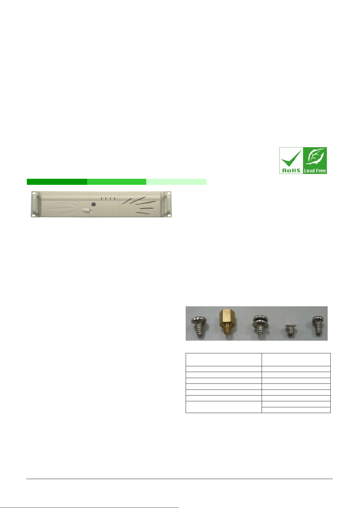
Figure 1: RACK-2100G Front Panel
ABOUT THE RACK-2100G
The 2U, metal RACK-2100G AT/ATX compatible rackmount
industrial chassis is designed to operate reliably in industrial
environments where it will be exposed to dust, wide temperature
variations, shocks and vibrations.
SPECIFICATONS
Form Factor: Standard 2U, 19” wide
SBC Form Factor: Full-size, PICMG 1.3 slot CPU cards
Construction: Metal
Slots Number: 6-slot
Cooling: 2 x 8cm fans
Drive Bays:
o 1 x 5.25” Optical drive bay front accessible
o 1 x 3.5” FDD (floppy disk drive) or HDD (hard disk drive)
bay front accessible
o 1 x 3.5” Internal HDD bay
Dimensions (DxWxH):
o 576.9mm x 431mm x 88mm
Operating Temperature: 0~40°C
Relative Humidity: 5~95%
Vibration:
o 5 to 17Hz, 0.1” double amplitude displacement
o 17 to 640Hz, 1.5G acceleration peak to peak
Shock: 10G acceleration peak to peak
PACKING LIST
When unpacking the chassis, make sure the following items have
been shipped.
1 x Quick Installation Guide
1 x Power cord
2 x Handles and handle plates
1 x Screw set
1 x PCI/ISA card shock absorber
2 x Keys
PSU rear side mounting bracket (RACK-2100GR model only)
DETAILS OF INCLUDED SCREWS
The attached screw set includes five types of screws. Screws used
for chassis installation are shown below.
1 2 3 4 5
Peripherals/Parts
5.25” Disk Drives 5
3.5” FDD 5
3.5” HDD 1
2.5” HDD 4
Power Supply Unit 1
Rackmount Bracket 3
Backplane
Table 1: Screws for Peripheral/Parts
Screw Label
(refer to above picture)
3
2
RACK-2100G QIG IEI Technology Corp. Page 1
Page 2
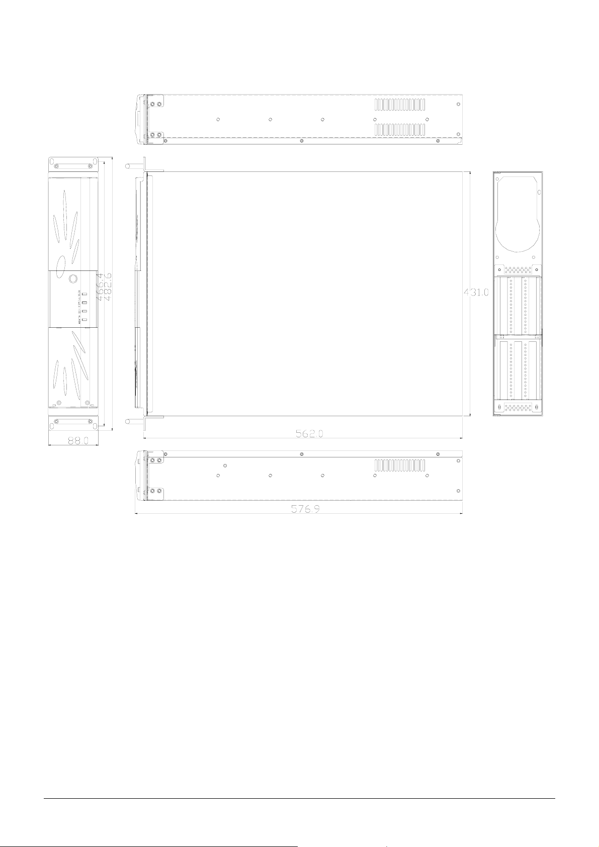
DIMENSION DRAWING
The dimensions of the RACK-2100G are shown below.
Figure 2: Dimension Drawing (mm)
RACK-2100G QIG IEI Technology Corp. Page 2
Page 3
INSTALLATION STEPS
Compete the following installation steps to install the RACK-2100G
chassis.
Step 1: Unpack the chassis.
Step 2: Install the front handles.
Step 3: Remove the top cover.
Step 4: Install a PSU.
Step 5: Install a backplane.
Step 6: Install a CPU card.
Step 7: Install PCI and ISA expansion cards.
Step 8: Install the backplane bracket.
Step 9: Install disk drives.
Step 10: Connect cables.
Step 11: Connect the PSU cable and interface cable.
Step 12: Reinstall the top cover.Step 0:
The installation steps outlined above are described in detail below.
STEP 1: UNPACK
The RACK-2100G is shipped in a plastic bag that is placed inside a
cardboard box. The items are also shipped with the chassis. When
unpacking the chassis:
Make sure all the items listed in the PACKING LIST section are
present.
Make sure the chassis has not been damaged in any way.
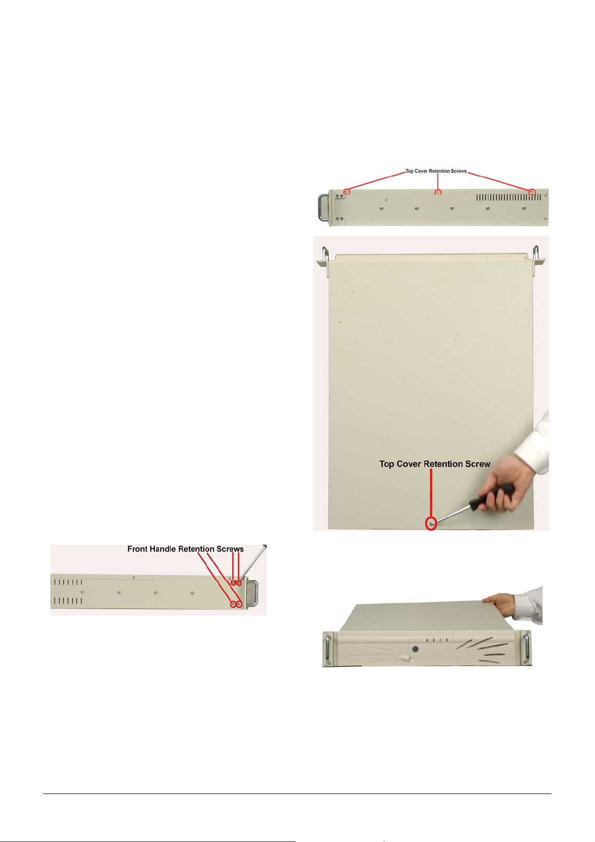
STEP 3: REMOVE THE TOP COVER
The top cover of the chassis is connected to the chassis with seven
retention screws, three each on the left and right side panels and
one near the rear of the top cover. Follow the steps below to remove
the top cover.
Step 1: Remove all seven retention screws. Remove six screws
from the sides of the chassis, and one retention screw
located near the rear of the top cover.
STEP 2: FRONT HANDLE INSTALLATION
Two handles are shipped with the RACK-2100G chassis. Each
handle is secured to the chassis with four retention screws, one each
on the left and right side panels near the front panel. Follow the
steps below to install the handles.
Step 1: Align the retention screw holes on the side of the
chassis with the retention screws holes in the handle.
Step 2: Insert four retention screws for each handle. Step 0:
Figure 3: Front Handle Retention Screws
Figure 4: Top Cover Retention Screws
Step 2: Slide the cover backwards, lifting gently. Step 0:
Figure 5: Remove the Top Cover
RACK-2100G QIG IEI Technology Corp. Page 3
Page 4

STEP 4: INSTALL A POWER SUPPLY UNIT (PSU)
Compatible IEI PS/2 and redundant type PSUs are listed in the table below.
Model No. Input Type Watt
+3.3V +5V +12V1 +12V2 -5V -12V +5Vsb
RACK-2100G
ACE-832AP-RS AC ATX 300W 28A 30A 15A N/A 0.3A 0.8A 2A
ACE-841AP-S-RS AC ATX 400W 28A 33A 20A N/A 0.5A 1A 2A
ACE-850AP-RS AC ATX 500W 27A 29A 18A 18A 0.3A 0.8A 2A
RACK-2100GR
ACE-R4130AP-RS AC ATX 300W 18A 25A 16A N/A 0.5A 0.5A 2A
ACE-R4140AP-RS AC ATX 400W 25A 25A 30A N/A N/A 0.8A 2A
ACE-C232-RS AC AT 230W N/A 20A 10A N/A N/A 0.5A 0.5A
Table 2: Compatible IEI PSUs.
STEP 4.1: INSTA LL A PS/2 TYPE POWER SUPPLY
Step 1: Correctly position the PSU at the rear of the chassis
making sure the power switch and the cable socket both
face outwards.
Step 2: Once the PSU has been correctly positioned, secure the
PSU to the chassis by inserting four retention screws
from the rear of the chassis.
Output Range
Step 3: Insert two screws through the bottom of the chassis and
rear mounting bracket of the power supply. Find the two
nuts supplied with the chassis and thread them onto the
screws and tighten until the PSU is secured to the
chassis. Step 0:
Figure 6: Insert PSU Retention Screws
Figure 7: Insert PSU Rear Bracket Screws and Nuts
RACK-2100G QIG IEI Technology Corp. Page 4
Page 5

STEP 4.2: INSTA LL A REDUNDANT TYPE POWER SUPPLY
NOTE:
Remove the power modules from the redundant PSU before
installing the PSU into the chassis.
Step 1: Remove the PSU bracket from the chassis by removing
three retention screws.
Step 3: Find the PSU rear mounting bracket that came with the
chassis and attach it to a redundant PSU with two
retention screws.
Figure 10: Attach the PSU Rear Mounting Bracket
Step 4: Mount the PSU in the chassis and reinsert the three
previously removed retention screws.
Figure 8: Remove the PSU Bracket
Step 2: Attach the PSU bracket to a redundant PSU with two
retention screws.
Figure 9: Attach the PSU Bracket to the PSU
Figure 11: Mount the PSU in the Chassis
Step 5: Find the two nuts supplied with the chassis and thread
them onto the chassis’ preinstalled screws that protrude
through the PSU rear mounting bracket until the PSU is
secured to the chassis.
Figure 12: Secure the PSU Rear Bracket
RACK-2100G QIG IEI Technology Corp. Page 5
Page 6

Step 6: Secure the PSU to the chassis with two additional
retention screws.
Figure 13: Secure the PSU to the Chassis
Step 7: Insert the power modules into the PSU and lock them in
place by tightening the thumbscrews.Step 0:
Figure 14: Insert the PSU Modules
STEP 5: BACKPLANE INSTALLATION
The IEI backplanes listed below are compatible with the
RACK-2100G chassis.
Model No. SBC Type PCI
PE-6SD PICMG 1.3 0 ATX
PE-6SD2 PICMG 1.3 1 ATX
Table 3: Compatible Backplane Modules
The backplane is installed into a backplane bracket. To install the
backplane follow the instructions below.
Step 1: Remove the backplane by removing the six retention
screws that secure the backplane bracket. Remove two
retention screws from the base and four from the rear of
the chassis.
PSU
Connector
Figure 15: Two Backplane Bracket Retention Screws on the
Base of the Chassis
Figure 16: Four Backplane Bracket Retention Screws at the
Rear of the Chassis
Step 2: Mount the backplane onto the backplane bracket. Make
sure the backplane is properly aligned with the
preformed holes in the bracket.
Step 3: Secure the backplane to the backplane bracket with
eight retention screws.Step 0:
Figure 17: Insert Eight Retention Screws
RACK-2100G QIG IEI Technology Corp. Page 6
Page 7

STEP 6: CPU CARD INSTALLATION
A CPU card must be installed into the backplane before the bracket
can be reinstalled into the chassis. Follow the steps below to install a
CPU card.
Step 1: Remove the slot cover at the rear of the backplane
bracket. To do this, remove the slot cover retention
screw at the side of the slot cover.
Figure 18: Remove the Slot Cover Retention Screw
Step 2: Slide the CPU card into the CPU socket on the
backplane. Make sure the CPU card also slides into the
corresponding plastic guide.
Step 3: Reinsert the previously removed slot cover retention
screw to secure the CPU card.
Step 4: To secure the CPU card in place, press the rubber end
of the PCI/ISA card shock absorber against the top of
the CPU card and align the shock absorber screw holes
with the backplane bracket screw holes.
Figure 20: Insert Two Shock Absorber Retention Screws
Step 5: Insert two retention screws to secure the shock
absorber to the backplane bracket.Step 0:
STEP 7: PCI/ISA EXPANSION CARD
INSTALLATION
The RACK-2100G/R supports up to five PCI/ISA expansion cards. If
a PCI expansion card or an ISA expansion card is being installed
please follow the instructions below.
Step 1: Remove the slot cover at the back of the backplane
bracket. To do this, remove the slot cover retention
screw on the side of the slot cover.
Figure 19: Secure the CPU Card to the Backplane Bracket
Step 2: Slide the PCI/ISA expansion card into a reserved
PCI/ISA socket on the backplane.
Step 3: To secure the PCI/ISA expansion card, reinsert the
previously removed slot cover retention screw. Step 0:
STEP 8: BACKPLANE BRACKET
REINSTALLATION
After the backplane, CPU card and any expansion cards have been
secured to the backplane bracket, the backplane bracket can be
reinstalled into the chassis.
Step 1: Mount the backplane bracket in the chassis. Make sure
the retention screw holes of the bracket are aligned with
the screw holes in the base and at the back of the
chassis.
Step 2: Secure the backplane bracket to the chassis with the six
previously removed retention screws. Insert two
retention screws on the base of the chassis and four
retention screws at the rear of the chassis.Step 0:
RACK-2100G QIG IEI Technology Corp. Page 7
Page 8

Figure 21: Backplane Bracket Chassis Retention Screws
Figure 22: Backplane Bracket Rear Panel Retention Screws
STEP 9: DISK DRIVE INSTALLATION
The RACK-2100G/GR chassis can support:
o 1 x FDD, 1 x HDD and 1 x Optical drive, or
o 2 x HDDs and 1 x Optical drive
One 3.5” FDD/HDD drive and one optical drive are mounted into a
single drive bracket. Another HDD is installed into an internal 3.5”
drive bracket. Follow the steps in the sections below to install the
drives.
STEP 9.1: INTERNAL 3.5"HDD DRIVE BRACKET
Follow the steps below to install an HDD in the internal 3.5” HDD
bracket.
Figure 23: 3.5"HDD Bracket Retention Screws
Step 2: Mount the HDD in the bracket. Make sure the HDD does
not block any of the retention screw holes at the corners
of the bracket and that the HDD PCB board is facing the
bottom of the bracket.
Step 3: Insert four retention screws, two on each side of the
bracket, to secure the HDD.
Figure 24: HDD Retention Screws (Opposite Side Similar)
Step 4: Once the HDD is secured, the HDD bracket can be
reinstalled. Remount the bracket making sure the power
connector and the IDE/SATA connector of HDD face the
main drive bracket and reinsert the previously removed
retention screws.Step 0:
Step 1: Remove the 3.5” internal HDD bracket by removing the
four retention screws that attach the bracket to the
chassis base.
Figure 25: HDD Bracket Retention Screws
RACK-2100G QIG IEI Technology Corp. Page 8
Page 9

STEP 9.2: FDD/HDD AND OPTICAL DRIVE BRACKET
The main drive bracket can support one FDD or HDD and one
optical drive. Follow the steps below to install the drives.
Step 1: Remove the retention screws that connect the drive
bracket to the chassis.
documentation that came with the CPU card. The
connectors provided with the chassis are listed below.
No. Name
1
Figure 26: Main Drive Bracket Retention Screws
Step 2: Mount the drives into the bracket. Make sure the power
connectors and the IDE/SATA connectors are at the rear
of the bracket.
Step 3: Both the FDD/HDD and 5.25” optical drive are secured
with four retention screws, two on each side of the
bracket.
Power LED cable
1
Reset Switch cable
1
HDD LED cable
1
Power switch cable
Table 4: Chassis Front Panel Connectors
STEP 11: CABLE CONNECTIONS
Follow the steps below to connect the power and ribbon cables.
Step 1: Connect the power cables from the PSU to the
backplane, full-size CPU card, HDD, FDD, cooling fan
and CD drive power connectors.
Figure 27: FDD/HDD and Optical Drive Retention Screws
Step 4: Remount the main drive bracket into the chassis and
reinsert the previously removed retention screws.
Step 0:
STEP 10: CABLING
The front bezel of the RACK-2100G/GR has the following
items:
o 1 x Power LED
o 1 x HDD LED
o 1 x Power switch
o 1 x Reset button
These items are connected to the CPU card with cables. To
connect these items to the CPU card, refer to the technical
Step 2: Disk drive interface connectors must be connected to
the CPU card. Step 0:
STEP 12: COVER REINSTALLATION
Reinstall the chassis top cover after completing the above
procedures. To do this, slide the cover back over the chassis and
reinsert the previously removed retention screws.
CHASSIS MANTENANCE
WARNING:
1. Never attempt to remove the external panels or access any
internal components of the chassis while it is connected to a
power source. Always be sure to turn off and disconnect the
chassis from all power sources before attempting to access
the internal components. Failure to do so may seriously injury
the user or cause irreparable damage the internal components
of the chassis.
2. Take anti-static precautions whenever carrying out
maintenance on the system components. Failure to take
anti-static precautions can cause permanent system damage.
RACK-2100G QIG IEI Technology Corp. Page 9
Page 10

FAN REPLACEMENT
There are two 8cm cooling fans secured to a fan bracket inside
chassis. Follow the steps below to replace a fan.
Step 1: To remove the fan bracket, remove one fan bracket
retention screw from the right side of the chassis and
two internal fan bracket retention screws on the base of
the chassis.
F
AN FILTER REPLACEMENT
Follow the steps below to replace the fan filter.
Step 1: Open the fan filter cover at the right side of the chassis
front panel.
Figure 30: Fan Filter Cover
Figure 28: External Fan Bracket Retention Screw
Figure 29: Internal Fan Bracket Retention Screws
Step 2: Remove the retention screws that secure the fan to the
bracket.
Step 3: Replace the replacement fan and reinsert the previously
removed retention screws.
Step 4: Remount the fan bracket into the chassis and reinsert
the previously removed fan bracket retention screws.
Step 0:
Step 2: Replace the filter pad inside.
Step 3: Close the fan filter cover.Step 0:
RACK/CABINET INSTALLATION
Supporting rails, rack trays, or slide rails can be can be used with the
mounting holes on the sides of the chassis for rack or cabinet
installation.
Figure 31: Rack/Cabinet Side Panel Mounting Holes
Figure 32: Rack/Cabinet Front Panel Mounting Holes
BACKING UP DATA
NOTE:
If the system is running critical applications, find an
appropriate time to backup data and properly shut down the
system.
RACK-2100G QIG IEI Technology Corp. Page 10
 Loading...