

Page 1
IMB-Q770 Mic ro -ATX Motherboard
Page i
microATX Motherboard Supports 22nm LGA1155 Intel® Core™ i7/i5/i3
CPU with Intel® Q77, DDR3, Three Independent Displays via Dual
MODEL:
Rev. 1 .0 0 – 30 August, 2012
IEI Technolog y Corp.
IMB-Q770
HDMI/DVI-I, Dual In tel® PCIe GbE, USB 3.0, SATA 6G b/s,
Ten Serial Ports, HD Audio and RoHS
User Manual
Page 2

IMB-Q770 Mic ro -ATX Motherboard
Page ii
Date Version Changes
Revis ion
30 August, 2012
1.00 Initial release
Page 3

IMB-Q770 Mic ro -ATX Motherboard
Page iii
Copyright
COP YRIGHT NOTICE
The information in this document is subject to change without prior notice in order to
improve reliabilit y, design a nd func tion and does not r epresent a com mitm ent on the par t
of the manufacturer.
In no event will the manufacturer be liable for direct, indirect, special, incidental, or
consequential damages arising out of the use or inability to use the product or
documentation, even if advised of the possibility of such damages.
This document contains proprietary information protected by copyright. All rights are
reserved. No part of this manual may be reproduced by any mechanical, e lectronic, or
other means in any form without prior written permission of the manufacturer.
TRADEMARKS
All registered tradem ark s and produc t nam es ment ioned here in are us ed for identif icatio n
purposes only and m ay be trademarks and/or registe red trademarks of their respecti ve
owners.
Page 4
IMB-Q770 Mic ro -ATX Motherboard
Page iv
Table of Contents
1 INTRODUCTION .......................................................................................................... 1
1.1 INTRODUCTION ........................................................................................................... 2
1.2 BENEFITS ................................................................................................................... 3
1.3 FEATURES ................................................................................................................... 3
1.4 CONNECTORS ............................................................................................................. 4
1.5 DIMENSIONS ............................................................................................................... 5
1.6 DATA FLOW ................................................................................................................ 6
1.7 TECHNICAL SPECIFICATIONS ...................................................................................... 7
2 PACKING LIST ........................................................................................................... 10
2.1 ANTI-STATIC PRECAUTIONS ....................................................................................... 11
2.2 UNPACKING PRECAUTIONS ........................................................................................ 11
2.3 PACKING LIST ........................................................................................................... 12
2.4 OPTIONAL ITEMS ...................................................................................................... 13
3 CONNECTORS ........................................................................................................... 15
3.1 PERIPHERAL INTERFACE CONNECTORS ..................................................................... 16
3.1.1 IMB-Q770 Layout ............................................................................................ 16
3.1.2 Peripheral Interface Connectors ..................................................................... 17
3.1.3 External Interface Panel Connectors ............................................................... 18
3.2 INTERNAL PERIPHERAL CONNECTORS ...................................................................... 18
3.2.1 ATX Power Connector ..................................................................................... 18
3.2.2 Battery Connector ............................................................................................ 20
3.2.3 CPU Power Connector .................................................................................... 20
3.2.4 DDR3 DIMM Slots ........................................................................................... 21
3.2.5 Debug Port Connector ..................................................................................... 22
3.2.6 Digital I/O Connector ...................................................................................... 23
3.2.7 Fan Connector (CPU) ...................................................................................... 24
3.2.8 Fan Connector (System) .................................................................................. 25
3.2.9 Fan Connector (PCH) ...................................................................................... 26
3.2.10 Front Panel Audio Connector ........................................................................ 27
Page 5

IMB-Q770 Mic ro -ATX Motherboard
Page v
3.2.11 Front Panel Connector ................................................................................... 28
3.2.12 FW Programming Connector ......................................................................... 29
3.2.13 Infrared Interface Connector ......................................................................... 29
3.2.14 Keyboard/Mouse Connector .......................................................................... 30
3.2.15 PCIe Power Connector .................................................................................. 31
3.2.16 PCI Slot .......................................................................................................... 32
3.2.17 PCIe x16 Slot ................................................................................................. 33
3.2.18 PCIe x4 Slot ................................................................................................... 34
3.2.19 PCIe x1 Slot ................................................................................................... 34
3.2.20 SATA 3Gb/s Drive Connectors ....................................................................... 35
3.2.21 SATA 6Gb/s Drive Connectors ....................................................................... 36
3.2.22 Serial Port Connector, RS-422/485 ................................................................ 36
3.2.23 Serial Port Connectors, RS-232 ..................................................................... 37
3.2.24 SMBus Connector .......................................................................................... 39
3.2.25 SPI ROM Connector ...................................................................................... 40
3.2.26 TPM Connector .............................................................................................. 40
3.2.27 USB Connectors ............................................................................................. 42
3.3 EXTERNAL PERIPHERAL INTERFACE CONNECTOR PANEL ......................................... 43
3.3.1 Audio Connector .............................................................................................. 43
3.3.2 DVI Connector ................................................................................................. 44
3.3.3 Ethernet and USB Connector ........................................................................... 45
3.3.4 HDMI Connector ............................................................................................. 47
3.3.5 Serial Port Connector ...................................................................................... 47
4 INSTALLATION ......................................................................................................... 49
4.1 ANTI-STATIC PRECAUTIONS ...................................................................................... 50
4.2 INSTALLATION CONSIDERATIONS .............................................................................. 50
4.2.1 Socket LGA1155 CPU Installation .................................................................. 52
4.2.2 Socket LGA1155 Cooling Kit Installation ........................................................ 55
4.2.3 DIMM Installation ........................................................................................... 57
4.3 JUMPER SETTINGS .................................................................................................... 58
4.3.1 AT/ATX Power Select Jumper .......................................................................... 58
4.3.2 Clear CMOS Jumper ........................................................................................ 59
4.4 INTERNAL PERIPHERAL DEVICE CONNECTIONS ........................................................ 60
4.4.1 SATA Drive Connection ................................................................................... 60
Page 6
IMB-Q770 Mic ro -ATX Motherboard
Page vi
4.5 EXTERNAL PERIPHERAL INTERFACE CONNECTION ................................................... 62
4.5.1 Audio Connection ............................................................................................. 62
4.5.2 DVI Display Device Connection ...................................................................... 63
4.5.3 HDMI Connection ............................................................................................ 64
4.5.4 LAN Connection ............................................................................................... 65
4.5.5 Serial Device Connection ................................................................................ 66
4.5.6 USB Connection ............................................................................................... 67
4.6 INTEL
®
AMT SETUP PROCEDURE ............................................................................. 68
5 BIOS .............................................................................................................................. 70
5.1 INTRODUCTION ......................................................................................................... 71
5.1.1 Starting Setup ................................................................................................... 71
5.1.2 Using Setup ...................................................................................................... 71
5.1.3 Getting Help ..................................................................................................... 72
5.1.4 Unable to Reboot after Configuration Changes .............................................. 72
5.1.5 BIOS Menu Bar ................................................................................................ 72
5.2 MAIN ........................................................................................................................ 73
5.3 ADVANCED ............................................................................................................... 74
5.3.1 ACPI Configuration ......................................................................................... 75
5.3.2 RTC Wake Settings ........................................................................................... 76
5.3.3 Trusted Computing ........................................................................................... 77
5.3.4 CPU Configuration .......................................................................................... 79
5.3.5 SATA Configuration ......................................................................................... 81
5.3.6 Intel(R) Rapid Start Technology ....................................................................... 82
5.3.7 Intel TXT(LT) Configuration ............................................................................ 82
5.3.8 AMT Configuration .......................................................................................... 83
5.3.9 USB Configuration ........................................................................................... 84
5.3.10 F81216 Second Super IO Configuration ....................................................... 85
5.3.10.1 Serial Port n Configuration ..................................................................... 86
5.3.10.2 Serial Port 7 Configuration ..................................................................... 87
5.3.10.3 Serial Port 8 Configuration ..................................................................... 88
5.3.10.4 Serial Port 9 Configuration ..................................................................... 89
5.3.10.5 Serial Port 10 Configuration ................................................................... 90
5.3.11 F81866 Super IO Configuration .................................................................... 91
5.3.11.1 Serial Port n Configuration ..................................................................... 91
Page 7
IMB-Q770 Mic ro -ATX Motherboard
Page vii
5.3.12 F81866 H/W Monitor ..................................................................................... 97
5.3.12.1 Smart Fan Mode Configuration .............................................................. 98
5.3.13 Serial Port Console Redirection .................................................................. 100
5.3.13.1 Console Redirection Settings ................................................................ 102
5.3.14 IEI Feature ................................................................................................... 104
5.4 CHIPSET ................................................................................................................. 105
5.4.1 PCH-IO Configuration .................................................................................. 106
5.4.1.1 PCH Azalia Configuration ...................................................................... 107
5.4.2 System Agent (SA) Configuration .................................................................. 108
5.4.2.1 Graphics Configuration ........................................................................... 109
5.4.2.2 Memory Configuration ............................................................................ 111
5.5 BOOT ....................................................................................................................... 112
5.6 SECURITY ................................................................................................................ 114
5.7 EXIT ........................................................................................................................ 115
6 SOFTWARE DRIVERS ............................................................................................. 117
6.1 AVAILABLE SOFTWARE DRIVERS ............................................................................. 118
6.2 SOFTWARE INSTALLATION ....................................................................................... 118
6.3 CHIPSET DRIVER INSTALLATION ............................................................................. 120
6.4 GRAPHICS DRIVER INSTALLATION .......................................................................... 123
6.5 LAN DRIVER INSTALLATION .................................................................................. 126
6.6 AUDIO DRIVER INSTALLATION ............................................................................... 130
6.7 INTEL® RAPID STORAGE TECHNOLOGY DRIVER INSTALLATION ............................ 132
6.8 USB 3.0 DRIVER INSTALLATION ............................................................................. 135
6.9 INTEL® AMT DRIVER INSTALLATION .................................................................... 138
A BIOS OPTIONS ........................................................................................................ 141
B ONE KEY RECOVERY ........................................................................................... 145
B.1 ONE KEY RECOVERY INTRODUCTION .................................................................... 146
B.1.1 System Requirement ....................................................................................... 147
B.1.2 Supported Operating System ......................................................................... 148
B.2 SETUP PROC EDURE FOR WINDOWS ........................................................................ 149
B.2.1 Hardware and BIOS Setup ............................................................................ 150
B.2.2 Create Partitions ........................................................................................... 150
B.2.3 Install Operating System, Drivers and Applications ..................................... 154
Page 8

IMB-Q770 Mic ro -ATX Motherboard
Page viii
B.2.4 Building the Recovery Partition .................................................................... 155
B.2.5 Create Factory Default Image ....................................................................... 157
B.3 AUTO RECOVERY SETUP PROCEDURE .................................................................... 162
B.4 SETUP PROC EDURE FOR LINUX .............................................................................. 166
B.5 RECOVERY TOOL FUNCTIONS ................................................................................ 170
B.5.1 Factory Restore ............................................................................................. 171
B.5.2 Backup System ............................................................................................... 172
B.5.3 Restore Your Last Backup .............................................................................. 173
B.5.4 Manual ........................................................................................................... 174
B.6 RESTORE SYSTEMS FROM A LINUX SERVER THROUGH LAN .................................. 175
B.6.1 Configure DHCP Server Settings .................................................................. 176
B.6.2 Configure TFTP Settings ............................................................................... 177
B.6.3 Configure One Key Recovery Server Settings ............................................... 178
B.6.4 Start the DHCP, TFTP and HTTP ................................................................. 179
B.6.5 Create Shared Directory ................................................................................ 179
B.6.6 Setup a Client System for Auto Recovery ...................................................... 180
B.7 OTHER INFORMATION ............................................................................................ 183
B.7.1 Using AHCI Mode or ALi M5283 / VIA VT6421A Controller ....................... 183
B.7.2 System Memory Requirement ........................................................................ 185
C TERMINOLOGY ..................................................................................................... 186
D WATCHDOG TIMER .............................................................................................. 190
E HAZARDOUS MATERIALS DISCLOSURE ....................................................... 193
E.1 HAZARDOUS MATERIALS DISCLOSURE TAB LE FOR IPB PRODUCTS CERTIFIED AS
ROHS COMPLIANT UNDER 2002/95/EC WITHOUT MERCURY ..................................... 194
Page 9
IMB-Q770 Mic ro -ATX Motherboard
Page ix
List of Figures
Figure 1-1: IMB-Q770 ...................................................................................................................... 2
Figure 1-2: Connectors
Figure 1-3: IMB-Q770 Dimensions (mm)
Figure 1-4: Data Flow Diagram
Figure 3-1: Connectors and Jumpers
Figure 3-2: ATX Power Connector Pinout Location
Figure 3-3: Battery Connector Locations
Figure 3-4: CPU Power Connector Location
Figure 3-5: DDR3 DIMM Slot Locations
Figure 3-6: Debug Port Connector Location
Figure 3-7: Digital I/O Connector Location
Figure 3-8: CPU Fan Connector Location
Figure 3-9: System Fan Connector Location
Figure 3-10: PCH Fan Connector Location
Figure 3-11: Front Panel Audio Connector Location
Figure 3-12: Front Panel Connector Location
Figure 3-13: FW Programming Connector Location
Figure 3-14: Infrared Connector Location
.................................................................................................................. 4
...................................................................................... 5
...................................................................................................... 6
.........................................................................................16
..................................................................19
...................................................................................20
..............................................................................21
......................................................................................22
..............................................................................22
................................................................................23
..................................................................................24
.............................................................................25
................................................................................26
................................................................27
...........................................................................28
.................................................................29
..................................................................................30
Figure 3-15: Keyboard/Mouse Connector Location
Figure 3-16: PCIe Power Location
Figure 3-17: PCI Slot Locations
Figure 3-18: PCIe x16 Slot Location
Figure 3-19: PCIe x4 Slot Locations
Figure 3-20: PCIe x1 Slot Locations
Figure 3-21: SATA 3Gb/s Drive Connector Location
Figure 3-22: SATA 6Gb/s Drive Connector Location
Figure 3-23: RS-422/485 Connector Location
Figure 3-24: Serial Port Connector Loca tion
Figure 3-25: SMBus Connector Location
Figure 3-26: SPI Connector Location
..................................................................31
..............................................................................................32
..................................................................................................33
...........................................................................................33
...........................................................................................34
...........................................................................................35
................................................................35
................................................................36
............................................................................37
.............................................................................38
...................................................................................39
.........................................................................................40
Page 10

IMB-Q770 Mic ro -ATX Motherboard
Page x
Figure 3-27: TPM Connector Location ........................................................................................41
Figure 3-28: USB Connector Pinout Locations
Figure 3-29: External Peripheral Interface Connector
Figure 3-30: Audio Connector
Figure 3-31: Ethernet Connector
Figure 3-32: Serial Port Connector Pin o u ts
Figure 4-1: Disengage the CPU Socket Load Lever
Figure 4-2: Remove Protective Cover
Figure 4-3: Insert the Socket LGA1155 CPU
Figure 4-4: Close the Socket LGA1155
Figure 4-5: Cooling Kits (CF-1156A-RS, CF-1156B-RS, CF-1156C-RS, CF-1156D-RS)
Figure 4-6: Cooling Kit Support Bracket
Figure 4-7: DIMM Installation
Figure 4-8: AT/ATX Power Select Jumper Location
Figure 4-9: Clear BIOS Jumper Location
Figure 4-10: SATA Drive Cable Connection
Figure 4-11: SATA Power Drive Connection
Figure 4-12: Audio Connector
.........................................................................42
..............................................................43
.....................................................................................................44
.................................................................................................45
...............................................................................48
..................................................................52
.........................................................................................53
..............................................................................54
.......................................................................................54
..........55
....................................................................................56
.......................................................................................................57
..................................................................59
...................................................................................60
...............................................................................61
..............................................................................62
.....................................................................................................63
Figure 4-13: DVI Connector
Figure 4-14: HDMI Connection
Figure 4-15: LAN Connection
Figure 4-16: Serial Device Connector
Figure 4-17: USB Connector ........................................................................................................68
Figure 6-1: Introduction Screen
Figure 6-2: Available Drivers
Figure 6-3: Chipset Driver Welcome Screen
Figure 6-4: Chipset Driver License Agreement
Figure 6-5: Chipset Driver Read Me File
Figure 6-6: Chipset Driver Setup Operations
Figure 6-7: Chipset Driver Installation Finish Screen
Figure 6-8: Graphics Driver Welcome Screen
Figure 6-9: Graphics Driver License Agreement
Figure 6-10: Graphics Driver Setup Operations
Figure 6-11: Graphics Driver Installation Finish Screen
Figure 6-12: Windows Control Panel
.........................................................................................................64
....................................................................................................65
......................................................................................................66
.........................................................................................67
................................................................................................119
.....................................................................................................119
............................................................................120
.......................................................................121
..................................................................................121
..........................................................................122
.............................................................123
.........................................................................124
.....................................................................124
......................................................................125
........................................................125
........................................................................................126
Page 11

IMB-Q770 Mic ro -ATX Motherboard
Page xi
Figure 6-13: System Control Panel ...........................................................................................126
Figure 6-14: Device Manager List
Figure 6-15: Update Driver Software Window
Figure 6-16: Locate Driver Files
Figure 6-17: LAN Driver Installation
Figure 6-18: LAN Driver Installatio n Complete
Figure 6-19: InstallShield Wizard Welcome Screen
Figure 6-20: Audio Driver Software Configuration
Figure 6-21: Restart the Computer
Figure 6-22: SATA RAID Driver Welcome Screen
Figure 6-23: SATA RAID Driver License Agreement
Figure 6-24: SATA RAID Driver Read Me File
Figure 6-25: SATA RAID Driver Setup Operations
Figure 6-26: SATA RAID Driver Installation Finish Screen
Figure 6-27: USB 3.0 Driver Welcome Screen
Figure 6-28: USB 3.0 Driver License Agreement
Figure 6-29: USB 3.0 Driver Read Me File
Figure 6-30: USB 3.0 Driver Setup Operations
.............................................................................................127
.........................................................................128
................................................................................................128
.........................................................................................129
........................................................................129
................................................................130
..................................................................131
...........................................................................................131
...................................................................132
...............................................................133
..........................................................................133
..................................................................134
....................................................134
.........................................................................135
.....................................................................136
................................................................................136
........................................................................137
Figure 6-31: USB 3.0 Driver Installation Finish Screen
Figure 6-32: Intel® ME Driver Welcome Screen
Figure 6-33: Intel® ME Driver License Agreement
Figure 6-34: Intel® ME Driver Setup Ope ra tions
Figure 6-35: Intel® ME Driver Installation Finish Screen
Figure B-1: IEI One Key Recovery Tool Menu
Figure B-2: Launching the Recovery Tool
Figure B-3: Recovery Tool Setup Menu ...................................................................................151
Figure B-4: Command Prompt
Figure B-5: Partition Creation Commands
Figure B-6: Launching the Recovery Tool
Figure B-7: Manual Recovery Environment for Windows
Figure B-8: Building the Recovery Partition
Figure B-9: Press Any Key to Continue
Figure B-10: Press F3 to Boot into Recovery Mode
Figure B-11: Recovery Tool Menu
Figure B-12: About Symantec Ghost Window
..........................................................137
......................................................................139
..................................................................139
.....................................................................140
.......................................................140
.........................................................................146
...............................................................................151
..................................................................................................152
...............................................................................153
...............................................................................155
......................................................155
............................................................................156
...................................................................................156
................................................................157
............................................................................................157
.........................................................................158
Page 12

IMB-Q770 Mic ro -ATX Motherboard
Page xii
Figure B-13: Symantec Ghost Path ..........................................................................................158
Figure B-14: Select a Local Source Drive
Figure B-15: Select a Source Partition from Basic Drive
Figure B-16: File Name to Copy Image to
Figure B-17: Compress Image
Figure B-18: Image Creation Confirmation
Figure B-19: Image Creation Complete
Figure B-20: Image Creation Complete
Figure B-21: Press Any Key to Continue
Figure B-22: Auto Recovery Utility
Figure B-23: Launching the Recovery Tool
Figure B-24: Auto Recovery Environment for Windows
Figure B-25: Building the Auto Recovery Partition
Figure B-26: Factory Default Image Confirmation
Figure B-27: Image Creation Complete
Figure B-28: Press any key to continue
Figure B-29: Partitions for Linux
Figure B-30: Manual Recovery Environment for Linux
................................................................................159
.......................................................159
................................................................................160
...................................................................................................160
..............................................................................161
....................................................................................161
....................................................................................161
.................................................................................162
...........................................................................................163
.............................................................................163
........................................................163
.................................................................164
..................................................................164
....................................................................................165
...................................................................................165
...............................................................................................167
..........................................................168
Figure B-31: Access menu.lst in Linux (Text Mode)
Figure B-32: Recovery Tool Menu
Figure B-33: Recovery Tool Main Menu
Figure B-34: Restore Factory Default
Figure B-35: Recovery Complete Window
Figure B-36: Backup System
Figure B-37: System Backup Complete Window
Figure B-38: Restore Backup
Figure B-39: Restore System Backup Complete Window
Figure B-40: Symantec Ghost Window
...............................................................169
............................................................................................169
...................................................................................170
.......................................................................................171
...............................................................................172
.....................................................................................................172
....................................................................173
....................................................................................................173
......................................................174
....................................................................................174
Page 13

IMB-Q770 Mic ro -ATX Motherboard
Page xiii
List of Tables
Table 1-1: IMB-Q770 Specifications .............................................................................................. 9
Table 2-1: Packing List
Table 2-2: Optional Items
Table 3-1: Peripheral Interface Connectors
Table 3-2: Rear Panel Connectors
Table 3-3: ATX Power Connector Pinouts
Table 3-4: CPU Power Connector Pinouts
Table 3-5: Debug Port Connector Pinouts
Table 3-6: Digital I/O Connector Pinouts
Table 3-7: CPU Fan Connector Pinouts
Table 3-8: System Fan Connector Pinouts (SYS_FAN1)
Table 3-9: System Fan Connector Pinouts (SYS_FAN2)
Table 3-10: PCH Fan Connector Pinouts
Table 3-11: Front Panel Audio Connector Pinouts
Table 3-12: Front Panel Connector Pinouts
Table 3-13: FW Programming Connector Pinouts
Table 3-14: Infrared Connector Pinouts
Table 3-15: Keyboard/Mouse Connector Pinouts
.................................................................................................................13
.............................................................................................................14
...............................................................................18
..............................................................................................18
..................................................................................19
.................................................................................21
.................................................................................23
....................................................................................24
.....................................................................................25
..........................................................25
..........................................................26
....................................................................................26
...................................................................27
...............................................................................28
....................................................................29
.....................................................................................30
.....................................................................31
Table 3-16: PCIe Power Pinouts
Table 3-17: RS-422/485Connector Pinouts
Table 3-18: Serial Port Connector Pinouts
Table 3-19: SMBus Connector Pinouts
Table 3-20: SPI Connector Pinouts
Table 3-21: TPM Connector Pinouts ...........................................................................................41
Table 3-22: USB Port Connector Pinouts
Table 3-23: DVI Connector Pinouts
Table 3-24: Connector LEDs
Table 3-25: LAN and USB Connector Pinouts (LAN_USB1)
Table 3-26: LAN and USB Connector Pinouts (LAN_USB2)
Table 3-27: USB Connector Pinouts (R_USB1)
..................................................................................................32
................................................................................37
................................................................................38
......................................................................................39
.............................................................................................40
...................................................................................42
.............................................................................................44
........................................................................................................45
.....................................................46
.....................................................46
.........................................................................47
Page 14

IMB-Q770 Mic ro -ATX Motherboard
Page xiv
Table 3-28: HDMI Connector Pinouts .........................................................................................47
Table 3-29: Serial Port Connector Pinouts
Table 4-1: Jumpers
Table 4-2: AT/ATX Power Select Jumper Settings
Table 4-3: Clear BIOS Jumper Settings
Table 5-1: BIOS Navigation Keys
................................................................................48
.......................................................................................................................58
....................................................................59
......................................................................................59
................................................................................................72
Page 15

IMB-Q770 Mic ro -ATX Motherboard
Page xv
BIOS Menus
BIOS Menu 1: Main .......................................................................................................................73
BIOS Menu 2: Advanced
BIOS Menu 3: ACPI Configuration
BIOS Menu 4: RTC Wake Settings
BIOS Menu 5: Trusted Computing
BIOS Menu 6: CPU Configuration
BIOS Menu 7: SATA
BIOS Menu 8: Intel(R) Rapid Start Technology
BIOS Menu 9: Intel TXT(LT) Configuration
BIOS Menu 10: AMT Configuration
BIOS Menu 11: USB Configuration
BIOS Menu 12: Secondary Super IO Configuration
BIOS Menu 13: Serial Port n Configuration Menu
BIOS Menu 14: Super IO Configuration
BIOS Menu 15: Serial Port n Configuration Menu
BIOS Menu 16: Hardware Health Configuration
BIOS Menu 17: FAN 1 Configuration
BIOS Menu 18: Serial Port Console Redirection
Configuration .............................................................................................81
..............................................................................................................75
..............................................................................................75
..............................................................................................76
..............................................................................................78
...............................................................................................79
.........................................................................82
.................................................................................83
.............................................................................................83
.............................................................................................84
..................................................................86
.....................................................................86
......................................................................................91
.....................................................................91
........................................................................97
..........................................................................................99
.....................................................................101
BIOS Menu 19: Console Redirection Settings
BIOS Menu 20: IEI Feature
BIOS Menu 21: Chipset
BIOS Menu 22:PCH-IO Configuration
BIOS Menu 23:PCH-IO Configuration
BIOS Menu 24: System Agent (SA) Configuration ..................................................................109
BIOS Menu 25: Graphics Configuration
BIOS Menu 26: Graphics Configuration
BIOS Menu 27: Memory Configuration
BIOS Menu 28: Boot
BIOS Menu 29: Security
BIOS Menu 30:Exit
.........................................................................102
.........................................................................................................104
..............................................................................................................105
.......................................................................................106
.......................................................................................107
...................................................................................109
...................................................................................111
.....................................................................................112
...................................................................................................................112
.............................................................................................................114
......................................................................................................................115
Page 16

IMB-Q770 Mic ro -ATX Motherboard
Page xvi
BIOS Menu 31: IEI Feature .........................................................................................................166
Page 17

IMB-Q770 Mic ro -ATX Motherboard
Page 1
Chapter
1
1 Introduction
Page 18

IMB-Q770 Mic ro -ATX Motherboard
Page 2
1.1 In troduction
Figure 1-1: IMB-Q770
The IMB-Q770 is an ATX motherboard. It accepts a socket LGA1155 Intel® Core™ i7/i5/i3
quad/dual core processor and supports four 240-pin 1600/1333MH z dual-channel DDR3
SDRAM unbuffered DIMMs (system max. 32GB).
The integrated Intel® Q77 system Chipset supports two GbE LAN: one through the Intel®
82579 PHY with Intel® AMT 8.0 support and t he other through th e Intel® 82583V PCIe
controller.
The IMB-Q770 includes two HDMI connectors and one DVI-I connector. Exp ansion and
I/O include one PCI slot, one PCIe x16 slot, one PCI e x4 slot, one PCIe x1 slot, four USB
3.0 ports on the rear pan el, two USB 2.0 on the rear pane l, four U SB 2.0 by pin header,
four SATA 3Gb/s c onnectors, two SATA 6Gb/s connectors. Serial device c onnectivity is
provided by eight internal RS-232 connectors, one e xternal RS-232 connector and one
internal RS-232/422/485 connector.
Page 19

IMB-Q770 Mic ro -ATX Motherboard
Page 3
1.2 Benefits
Some of the IMB-Q770 motherboard benefits include:
Powerful graphics with multiple monitors
Staying connected with both wired LAN connections
Speedy running of multiple programs and applications
1.3 Features
Some of the IMB-Q770 motherboard features are listed below:
LGA1 155 Intel® Core™ i7/i5/i3 processor supported
Dual-channel DDR3 1600/1333MHz supports up to 32GB
Intel® PCIe GbE with Intel® AMT 8.0 supported
Supports three displays with two displays in combination of HDMI, DVI and
VGA
Supports PCI-Express generation 3.0 at 8GT/s I/O bandwidth
USB 3.0 and SATA 6Gb/s supported
Supports much scalable serial ports
IEI One Key Recovery solution allows you to create rapid OS backup and
recovery
Page 20

IMB-Q770 Mic ro -ATX Motherboard
Page 4
1.4 Connectors
The connectors on the IMB-Q770 are shown in the figure below.
Figure 1-2: Connectors
Page 21

IMB-Q770 Mic ro -ATX Motherboard
Page 5
1.5 Dimensions
The main dimensions of the IMB-Q770 are shown in the diagram below.
Figure 1-3: IMB-Q770 Dimensions (mm)
Page 22

IMB-Q770 Mic ro -ATX Motherboard
Page 6
1.6 Data Flow
Figure 1-4 shows the data flow between the system chipset, the CPU and other
components installed on the motherboard.
Figure 1-4: Data Flow Diagram
Page 23

IMB-Q770 Mic ro -ATX Motherboard
Page 7
1.7 Technical Specifications
IMB-Q770 technical specifications are listed below.
Specification/Model IMB-Q770
Form Factor
CPU
System Chipset
Graphics Engine
Display Output
Memory
Audio
BIOS
Digital I/O
Ethernet
Micro-ATX
LGA1 155 socket supports Intel® Core™ i7/i5/i3 quad/dual core
processor
Intel® Q77
Intel® HD Graphics Gen 7 supports DX11 and OpenCL 1.1
Full MPEG2, VC1, AVC Decode
Dual HDMI integrated in the Intel® Q77
DVI-I integrated in the Intel® Q77
Four 240-pin 1600/1333MHz dual-channel DDR3 SDRAM unbuffered
DIMMs supported (system max. 32GB)
Realtek ALC662 HD audio codec (Line-in, Line-out, Mi c )
UEFI BIOS
24-bit Digital I/O (12-bit input, 12-bit output)
Intel® 82583V PCIe controller
Super I/O
Watchdog Timer
Expansion
PCI
PCIe
I/O Interface Connectors
Audio Connectors
Intel® 82579 PHY with Intel® AMT 8.0 supported
Fintek F81866
Software programmable supports 1~255 sec. system reset
One PCI slot
One PCIe x16 slot
One PCIe x4 slot
One PCIe x1 slot
Three external audio jacks (Line-in, Lin e-out, Mic)
Page 24

IMB-Q770 Mic ro -ATX Motherboard
Page 8
Specification/Model IMB-Q770
Display port
Ethernet
Keyboard/Mouse
TPM
Front Panel
Front Audio
SMBUS
I2C
IR
Fan
Serial Ports
One DVI-I port
Two HDMI ports
Two RJ-45 GbE ports
One 6-pin wafer for PS/2 KB/MS
One 20-pin header
1 x Front panel connector (power LED, HDD LED, speaker, power
button, reset button)
One 10-pin header
One 4 pin wafer
One 4 pin wafer
One 5 pin header
One 4-pin CPU fan connector
Two 3-pin system fan connectors
One external RS-232 serial port
Eight RS-232 via internal two 40-pin box headers
One RS-422/485 via internal 4-pin wafer
USB ports
Serial ATA
Environmental and Power Specifications
Power Supply
Power Consumption
Operating Temperature
Humidity
Four external USB 3.0 ports on rear IO
Two external USB 2.0 ports on rear IO
Four internal USB 2.0 ports by pin header
Two SATA 6Gb/s connectors
Four SATA 3Gb/s connectors
ATX power supply
3.3V@0.31A, 5V@2.91A, 12V@0.51A, 12V@2.12A, -12V@0.10A
(Intel® Core™ i3 3200 3.2GHZ CPU with four 1333MHz 1GB DDR3
memory)
-10ºC ~ 60ºC
5% ~ 95% (non-condensing)
Page 25

IMB-Q770 Mic ro -ATX Motherboard
Page 9
Specification/Model IMB-Q770
Physical Specifications
Dimensions
Weight GW/NW
Table 1-1: IMB-Q770 Specifications
244 mm x 244 mm
1200 g / 700 g
Page 26

IMB-Q770 Mic ro -ATX Motherboard
Page 10
Chapter
2
2 Packing List
Page 27

IMB-Q770 Mic ro -ATX Motherboard
Page 11
2.1 Anti-static Precautions
WARNING!
Static electricity can destroy certain electronics. Make sure to follow the
ESD precautions to preve nt damage to the product, and injur y to the
user.
Make sure to adhere to the following guidelines:
Wear an anti-static wristband: Wearing an anti-static wristband can prev ent
electrostatic discharge.
Self-grounding: T ouch a grounded conductor every few minutes to discharge
any excess static buildup.
Use an anti-static pad: When configuring any circuit board, place it on an
anti-static mat.
Only handle the edges of the PCB: Don't touch the surface of the
motherboard. Hold the motherboard by the edges when handling.
2.2 Unpacking Precautions
When the IMB-Q770 is unpacked, please do the following:
Follow the antistatic guidelines above.
Make sure the packing box is facing upwards when opening.
Make sure all the packing list items are present.
Page 28
IMB-Q770 Mic ro -ATX Motherboard
Page 12
2.3 Packing Lis t
NOTE:
If any of the components l isted in the checklist belo w are missing, do
not proceed with the installat ion. Cont act the I EI reseller or vendor the
IMB-Q770 was purchas ed from or contact an IEI sales represent ative
directly by sending an email to sales@iei.com.tw.
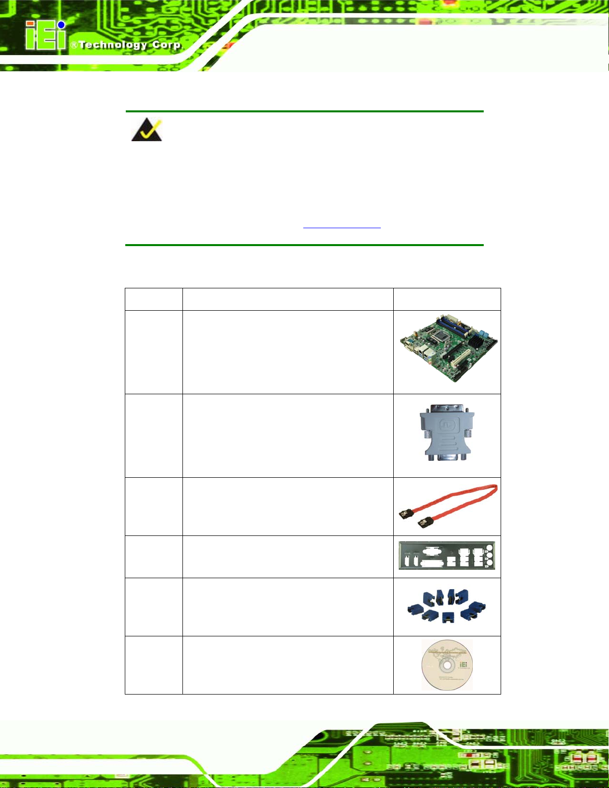
The IMB-Q770 is shipped with the following components:
Quantity Item and Part Nu mber Ima g e
1 IMB-Q770 motherboard
1 DVI-I to VGA adapter
(P/N: 33Z00-000031-RS)
4 SATA cable
(P/N: 32801-000703-200-RS)
1 I/O shielding
(P/N: 45014-0042C0-00-RS)
1 Mini jumper pack (2.54mm)
1 Utility CD
 Loading...