

Page 1
IMBA-Q454-R10 User Manual
IMBA-Q454
MODEL:
IMBA-Q454-R10
ATX Motherboard for Intel® Core™2 Duo/ Quad with
1333/1066/800 MHz FSB, Dual Gigabit GbE, Intel® AMT 5.0, PCI,
PCIe x4, PCIe x16, VGA, SATA II with RAID 0,1,5,10, HD Audio,
RoHS Compliant
User Manual
Rev. 1.00 6 March, 2009
Page i
Page 2
Date Version Changes
6 March, 2009 1.00 Initial release
IMBA-Q454-R10 User Manual
Revision
Page ii
Page 3

IMBA-Q454-R10 User Manual
COPYRIGHT NOTICE
The information in this document is subject to change without prior notice in order to
improve reliability, design and function and does not represent a commitment on the part
of the manufacturer.
In no event will the manufacturer be liable for direct, indirect, special, incidental, or
consequential damages arising out of the use or inability to use the product or
documentation, even if advised of the possibility of such damages.
This document contains proprietary information protected by copyright. All rights are
Copyright
reserved. No part of this manual may be reproduced by any mechanical, electronic, or
other means in any form without prior written permission of the manufacturer.
TRADEMARKS
All registered trademarks and product names mentioned herein are used for identification
purposes only and may be trademarks and/or registered trademarks of their respective
owners.
Page iii
Page 4
IMBA-Q454-R10 User Manual
Table of Contents
1 INTRODUCTION........................................................................................................ 16
1.1 IMBA-Q454-R10 MOTHERBOARD OVERVIEW ........................................................ 17
1.1.1 Benefits............................................................................................................. 18
1.1.2 Features ........................................................................................................... 18
1.1.3 Board Dimensions............................................................................................ 18
1.1.4 External Peripheral Interface Panel Dimensions............................................ 19
1.2 DATA FLOW.............................................................................................................. 20
1.3 TECHNICAL SPECIFICATIONS: ................................................................................... 20
2 UNPACKING............................................................................................................... 24
2.1 ANTI-STATIC PRECAUTIONS...................................................................................... 25
2.2 UNPACKING.............................................................................................................. 25
2.3 UNPACKING CHECKLIST........................................................................................... 26
2.3.1 Package Contents............................................................................................. 26
2.3.2 Optional Items.................................................................................................. 27
3 CONNECTOR PINOUTS........................................................................................... 29
3.1 PERIPHERAL INTERFACE CONNECTORS..................................................................... 30
3.1.1 IMBA-Q454-R10 Layout.................................................................................. 30
3.1.2 Peripheral Interface Connectors ..................................................................... 31
3.1.3 External Interface Panel Connectors............................................................... 32
3.2 INTERNAL PERIPHERAL CONNECTORS...................................................................... 33
3.2.1 ATX CPU Power Connector ............................................................................ 33
3.2.2 ATX Power Connector ..................................................................................... 34
3.2.3 Audio Connector .............................................................................................. 35
3.2.4 Digital I/O Connector...................................................................................... 36
3.2.5 Fan Connectors, CPU and Northbridge.......................................................... 37
3.2.6 Fan Connector, System..................................................................................... 38
3.2.7 Floppy Disk Connector.................................................................................... 39
3.2.8 Front Panel Connector.................................................................................... 40
3.2.9 Infrared Interface Connector (5-pin)............................................................... 41
Page iv
Page 5

IMBA-Q454-R10 User Manual
3.2.10 PCI Express x4 Slot........................................................................................ 42
3.2.11 PCI Express x16 Slot...................................................................................... 44
3.2.12 PCI Slot.......................................................................................................... 46
3.2.13 SATA Drive Connectors ................................................................................. 49
3.2.14 S/PDIF Connector ......................................................................................... 50
3.2.15 Serial Port Connectors .................................................................................. 51
3.2.16 SPI Flash Connector...................................................................................... 52
3.2.17 USB Connectors............................................................................................. 53
3.3 EXTERNAL INTERFACE CONNECTORS ....................................................................... 54
3.3.1 Audio Connector .............................................................................................. 55
3.3.2 Ethernet Connector.......................................................................................... 56
3.3.3 Keyboard and Mouse Connector..................................................................... 57
3.3.4 Parallel Port Connector .................................................................................. 58
3.3.5 Serial Port Connector...................................................................................... 59
3.3.6 USB Ports......................................................................................................... 59
3.3.7 VGA Connector................................................................................................ 60
4 INSTALLATION ......................................................................................................... 61
4.1 ANTI-STATIC PRECAUTIONS...................................................................................... 62
4.2 INSTALLATION CONSIDERATIONS.............................................................................. 63
4.2.1 Installation Notices.......................................................................................... 63
4.3 CPU, CPU COOLING KIT AND DIMM INSTALLATION.............................................. 64
4.3.1 Socket LGA775 CPU Installation.................................................................... 64
4.3.2 Socket LGA775 CF-520 Cooling Kit Installation............................................ 68
4.3.3 DIMM Installation........................................................................................... 70
4.4 JUMPER SETTINGS .................................................................................................... 72
4.4.1 Clear CMOS Jumper........................................................................................ 72
4.4.2 iTPM Setup Jumper.......................................................................................... 74
4.5 CHASSIS INSTALLATION............................................................................................ 74
4.5.1 Airflow.............................................................................................................. 75
4.5.2 Dual RS-232 Cable with Slot Bracket.............................................................. 75
4.5.3 Single RS-232 Cable with Slot Bracket............................................................ 76
4.5.4 SATA Drive Connection ................................................................................... 77
4.5.5 USB Cable (Dual Port) with Slot Bracket ....................................................... 79
4.5.6 USB Cable (Four Port).................................................................................... 80
Page v
Page 6

4.6 EXTERNAL PERIPHERAL INTERFACE CONNECTION ................................................... 82
4.6.1 Keyboard and Mouse....................................................................................... 82
4.6.2 LAN.................................................................................................................. 83
4.6.3 Parallel Device Connection............................................................................. 84
4.6.4 Serial Device.................................................................................................... 85
4.6.5 USB.................................................................................................................. 86
4.6.6 VGA Monitor.................................................................................................... 87
4.6.7 Audio Connector .............................................................................................. 88
5 BIOS SETUP................................................................................................................ 90
5.1 INTRODUCTION......................................................................................................... 91
5.1.1 Starting Setup................................................................................................... 91
5.1.2 Using Setup...................................................................................................... 91
5.1.3 Getting Help..................................................................................................... 92
5.1.4 Unable to Reboot After Configuration Changes.............................................. 92
IMBA-Q454-R10 User Manual
5.1.5 BIOS Menu Bar................................................................................................ 92
5.2 MAIN........................................................................................................................ 93
5.3 ADVANCED............................................................................................................... 94
5.3.1 CPU Configuration.......................................................................................... 95
5.3.2 IDE Configuration........................................................................................... 97
5.3.2.1 IDE Master, IDE Slave............................................................................. 98
5.3.3 Floppy Configuration..................................................................................... 103
5.3.4 Super I/O Configuration ................................................................................ 104
5.3.5 Hardware Health Configuration.................................................................... 108
5.3.6 AHCI Configuration........................................................................................112
5.3.6.1 AHCI Port n.............................................................................................112
5.3.7 Intel AMT Configuration.................................................................................114
5.3.7.1 ME Subsystem Configuration ..................................................................115
5.3.8 Remote Access Configuration.........................................................................117
5.3.9 T rusted Computing......................................................................................... 120
5.3.10 USB Configuration....................................................................................... 121
5.4 PCI/PNP................................................................................................................. 122
5.5 BOOT...................................................................................................................... 125
5.5.1 Boot Settings Configuration........................................................................... 125
5.5.2 Boot Device Priority...................................................................................... 127
Page vi
Page 7
IMBA-Q454-R10 User Manual
5.5.3 Hard Disk Drives........................................................................................... 128
5.5.4 CD/DVD Drives............................................................................................. 129
5.5.5 Removable Drives.......................................................................................... 130
5.6 SECURITY............................................................................................................... 131
5.7 CHIPSETS................................................................................................................ 132
5.7.1 Northbridge Chipset Configuration............................................................... 133
5.7.2 Southbridge Chipset Configuration............................................................... 135
5.8 EXIT....................................................................................................................... 138
6 SOFTWARE DRIVERS............................................................................................ 140
6.1 AVAILABLE SOFTWARE DRIVERS ............................................................................ 141
6.2 ST ARTING THE DRIVER PROGRAM .......................................................................... 141
6.3 CHIPSET DRIVER .................................................................................................... 143
6.4 GRAPHICS DRIVER ................................................................................................. 145
6.5 LAN DRIVER ......................................................................................................... 149
6.6 AUDIO DRIVER....................................................................................................... 153
6.6.1 BIOS Setup..................................................................................................... 153
6.6.2 Driver Installation ......................................................................................... 154
6.7 INTEL
®
MATRIX STORAGE MANAGER DRIVER ....................................................... 155
6.8 INTEL® AMT (HECI) DRIVER............................................................................... 160
6.9 INTEL® AMT (SOL) DRIVER................................................................................. 163
7 INTEL® AMT SETUP .............................................................................................. 167
7.1 INTEL
7.2 INTEL
7.3 USING THE INTEL
®
AMT SETUP PROCEDURE........................................................................... 168
®
MANAGEMENT ENGINE BIOS EXTENSION................................................. 168
®
AMT WEB INTERFACE ............................................................. 173
8 ISMM SETUP ............................................................................................................ 177
8.1 ISMM INTRODUCTION ........................................................................................... 178
8.2 ISMM INSTALLATION............................................................................................. 178
8.3 VOLTAGE PAGE....................................................................................................... 180
8.3.1 Refresh Time Setting....................................................................................... 181
8.3.2 High Limit Value and Low Limit Value Setting.............................................. 181
8.4 FAN PAGE............................................................................................................... 182
8.4.1 Refresh Time Setting....................................................................................... 183
8.4.2 High Limit Value and Low Limit Value Setting.............................................. 183
Page vii
Page 8

8.4.3 Smart Fan Setting .......................................................................................... 184
8.4.3.1 On/Off Mode........................................................................................... 184
8.4.3.2 PWM Mode............................................................................................. 184
8.4.3.3 Automatic Mode...................................................................................... 185
8.5 TEMPERATURE PAGE .............................................................................................. 186
8.5.1 Refresh Time Setting....................................................................................... 187
8.5.2 High Limit Value and Low Limit Value Setting.............................................. 188
8.6 CASH DRA WER PAGE.............................................................................................. 189
8.7 WATCHDOG TIMER PAGE........................................................................................ 190
8.8 DIO PAGE .............................................................................................................. 191
8.8.1 GPO Information Setting............................................................................... 191
8.9 LOAD/SAVE PAGE................................................................................................... 192
A BIOS OPTIONS ........................................................................................................ 193
B TERMINOLOGY...................................................................................................... 197
IMBA-Q454-R10 User Manual
C DIGITAL I/O INTERFACE..................................................................................... 201
C.1 INTRODUCTION...................................................................................................... 202
C.2 DIO CONNECTOR PINOUTS.................................................................................... 202
C.3 ASSEMBLY LANGUAGE SAMPLES........................................................................... 203
C.3.1 Enable the DIO Input Function..................................................................... 203
C.3.2 Enable the DIO Output Function.................................................................. 203
D WA TCHDOG TIMER .............................................................................................. 204
E COMPATIBILITY.................................................................................................... 207
E.1 COMPATIBLE OPERATING SYSTEMS........................................................................ 208
E.2 COMPATIBLE PROCESSORS..................................................................................... 208
E.3 COMPATIBLE MEMORY MODULES.......................................................................... 209
F HAZARDOUS MATERIALS DISCLOSURE........................................................ 210
F.1 HAZARDOUS MATERIALS DISCLOSURE TABLE FOR IPB PRODUCTS CERTIFIED AS
ROHS COMPLIANT UNDER 2002/95/EC WITHOUT MERCURY......................................211
Page viii
Page 9
IMBA-Q454-R10 User Manual
List of Figures
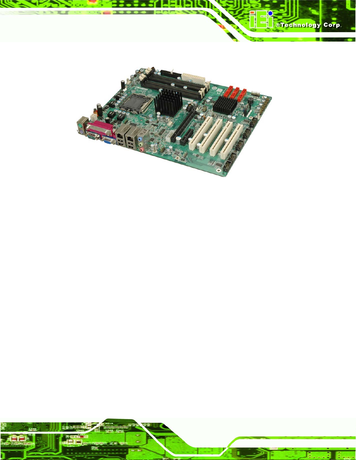
Figure 1–1: IMBA-Q454-R10 ........................................................................................................17
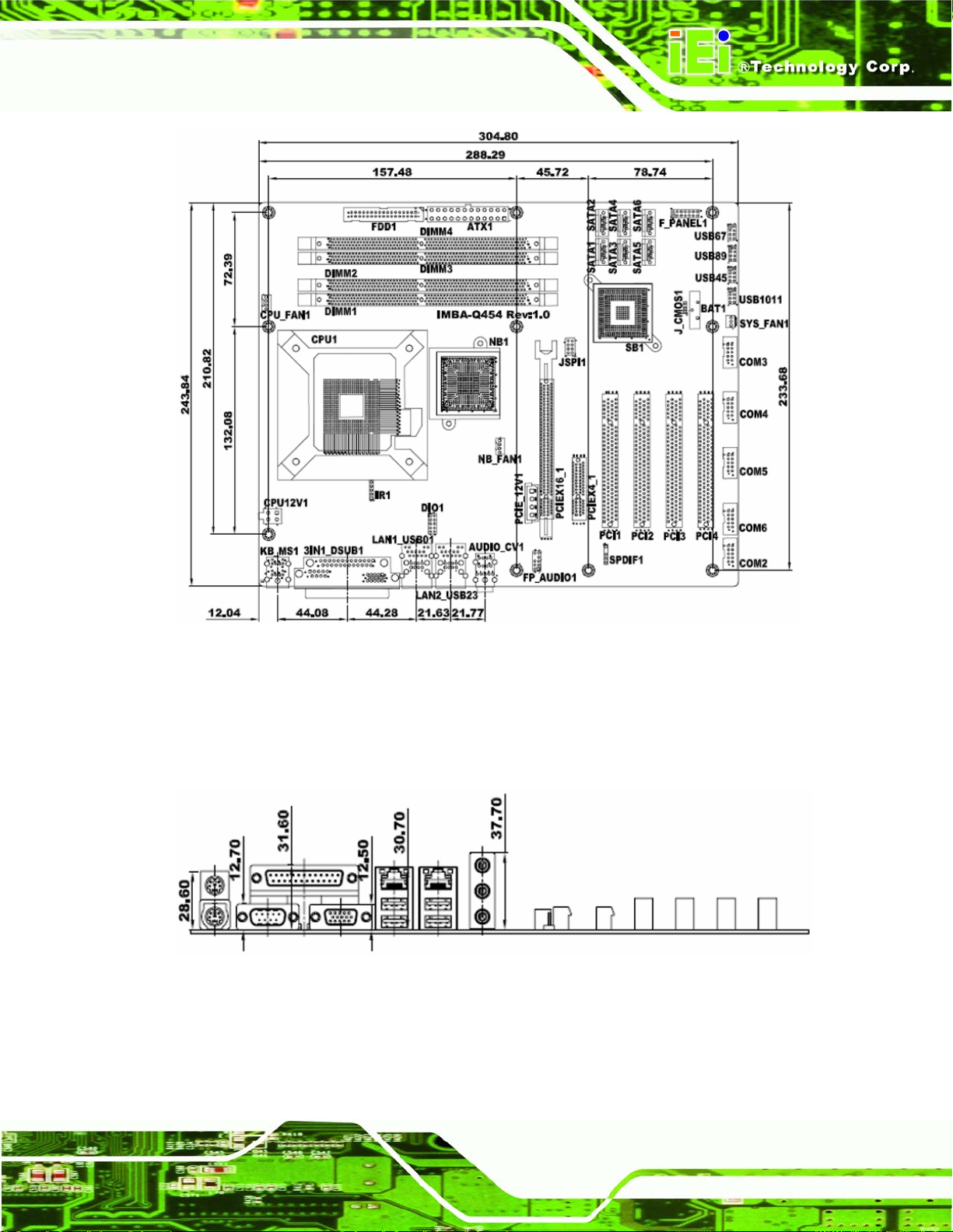
Figure 1-2: IMBA-Q454-R10 Dimensions (mm)..........................................................................19
Figure 1-3: External Interface Panel Dimensions (mm)............................................................19
Figure 1-4: Data Flow Block Diagram.........................................................................................20
Figure 3-1: Connector and Jumper Locations...........................................................................30
Figure 3-2: ATX Power Connector Location..............................................................................33
Figure 3-3: ATX Power Connector Pinout Locations................................................................34
Figure 3-4: Audio Connector Pinouts.........................................................................................35
Figure 3-5: Digital I/O Connector Locations ..............................................................................36
Figure 3-6: CPU and Northbridge Fan Connectors Location...................................................37
Figure 3-7: System Fan Connector Location.............................................................................38
Figure 3-8: 34-pin FDD Connector Location..............................................................................39
Figure 3-9: Front Panel Connector Pinout Locations...............................................................41
Figure 3-10: Infrared Connector Pinout Locations ...................................................................42
Figure 3-11: PCIe x4 Connector Locations................................................................................43
Figure 3-12: PCIe x16 Connector Location................................................................................44
Figure 3-13: PCI Slot Location ....................................................................................................47
Figure 3-14: SATA Drive Connector Locations.........................................................................50
Figure 3-15: SPDIF Connector Pinout Locations......................................................................51
Figure 3-16: Serial Port Connectors Pinout Locations.............................................................52
Figure 3-17: SPI Flash Connector Pinouts.................................................................................53
Figure 3-18: USB Connector Pinout Locations.........................................................................54
Figure 3-19: IMBA-Q454-R10 External Interface Connectors...................................................55
Figure 3-20: Audio Connector.....................................................................................................55
Figure 3-21: Ethernet Connector.................................................................................................56
Figure 3-22: PS/2 Connector .......................................................................................................57
Figure 3-23: Parallel Port Connector Location..........................................................................58
Figure 3-24: Serial Port Pinout Locations..................................................................................59
Figure 3-25: VGA Connector .......................................................................................................60
Figure 4-1: Intel LGA775 Socket .................................................................................................65
Page ix
Page 10

Figure 4-2: Remove the CPU Socket Protective Shield............................................................66
Figure 4-3: Open the CPU Socket Load Plate............................................................................66
Figure 4-4: Insert the Socket LGA775 CPU................................................................................67
Figure 4-5: Cooling Kit.................................................................................................................68
Figure 4-6: Securing the Heat sink to the PCB Board ..............................................................69
Figure 4-7: Installing a DIMM.......................................................................................................71
Figure 4-8: Clear CMOS Jumper .................................................................................................73
Figure 4-9: iTPM Setup Jumper Locations ................................................................................74
Figure 4-10: Dual RS-232 Cable Installation..............................................................................76
Figure 4-11: Single RS-232 Cable Installation ...........................................................................77
Figure 4-12: SATA Drive Cable Connection...............................................................................78
Figure 4-13: SATA Power Drive Connection..............................................................................79
Figure 4-14: Dual USB Cable Connection..................................................................................80
Figure 4-15: Four Port USB Cable Connection..........................................................................81
IMBA-Q454-R10 User Manual
Figure 4-16: PS/2 Keyboard/Mouse Connector.........................................................................83
Figure 4-17: LAN Connection......................................................................................................84
Figure 4-18: Parallel Device Connector......................................................................................85
Figure 4-19: Serial Device Connector.........................................................................................86
Figure 4-20: USB Connector........................................................................................................87
Figure 4-21: VGA Connector .......................................................................................................88
Figure 4-22: Audio Connector.....................................................................................................89
Figure 6-1: Start Up Screen ...................................................................................................... 142
Figure 6-2: Drivers..................................................................................................................... 142
Figure 6-3: Intel® Chipset Driver Directory............................................................................. 143
Figure 6-4: Intel® Setup Welcome Screen.............................................................................. 143
Figure 6-5: Intel® Chipset Driver License Agreement........................................................... 144
Figure 6-6: Readme File............................................................................................................ 144
Figure 6-7: Intel® Chipset Driver Complete Installation Screen........................................... 145
Figure 6-8: Graphics Driver File............................................................................................... 146
Figure 6-9: Graphics Driver Readme File................................................................................ 146
Figure 6-10: Graphics Driver Installation Welcome Screen.................................................. 147
Figure 6-11: GMA Driver License Agreement......................................................................... 147
Figure 6-12: GMA Driver Installing Notice .............................................................................. 148
Figure 6-13: GMA Driver Installation Complete...................................................................... 148
Figure 6-14: GMA Driver Installing Notice .............................................................................. 149
Page x
Page 11

IMBA-Q454-R10 User Manual
Figure 6-15: LAN Driver File..................................................................................................... 150
Figure 6-16: LAN Driver Welcome Screen .............................................................................. 150
Figure 6-17: LAN Driver License Agreement.......................................................................... 151
Figure 6-18: LAN Driver Setup Options................................................................................... 151
Figure 6-19: LAN Driver Installation Ready Window.............................................................. 152
Figure 6-20: LAN Driver Installation Progress........................................................................ 153
Figure 6-21: Audio Setup File................................................................................................... 154
Figure 6-22: InstallShield Wizard Welcome Screen............................................................... 154
Figure 6-23: Installation Wizard Finished................................................................................ 155
Figure 6-24: SATA RAID Setup Program Icon........................................................................ 156
Figure 6-25: InstallShield Wizard Setup Screen..................................................................... 156
Figure 6-26: Matrix Storage Manager Setup Screen.............................................................. 157
Figure 6-27: Matrix Storage Manager Welcome Screen ........................................................ 157
Figure 6-28: Matrix Storage Manager Warning Screen.......................................................... 158
Figure 6-29: Matrix Storage Manager License Agreement.................................................... 158
Figure 6-30: Matrix Storage Manager Readme File................................................................ 159
Figure 6-31: Matrix Storage Manager Setup Complete.......................................................... 160
Figure 6-32: AMT HECI Driver Directory ................................................................................. 161
Figure 6-33: AMT HECI Welcome Screen................................................................................ 161
Figure 6-34: AMT HECI License Agreement ........................................................................... 162
Figure 6-35: AMT HECI Driver Readme File............................................................................ 162
Figure 6-36: AMT HECI Driver Installation Complete............................................................. 163
Figure 6-37: IAMT Driver Directory.......................................................................................... 164
Figure 6-38: IAMT Welcome Screen......................................................................................... 164
Figure 6-39: IAMT License Agreement.................................................................................... 165
Figure 6-40: IAMT Readme File................................................................................................ 165
Figure 6-41: Completed Installation......................................................................................... 166
Figure 7-1: Intel® Active Management Technology Status Dialog....................................... 168
Figure 7-2: Intel® Current ME Password................................................................................. 169
Figure 7-3: Change Intel® ME Password ................................................................................ 170
Figure 7-4: Verify New Password............................................................................................. 170
Figure 7-5: Intel® AMT Configuration...................................................................................... 170
Figure 7-6: Provision Model ..................................................................................................... 171
Figure 7-7: Intel® AMT 5.0 Mode.............................................................................................. 171
Figure 7-8: Enterprise................................................................................................................ 172
Page xi
Page 12

Figure 7-9: Enable Network Interface...................................................................................... 172
Figure 7-10: Exit......................................................................................................................... 173
Figure 7-11: Intel® AMT Web Address .................................................................................... 174
Figure 7-12: Intel® AMT Web Login Dialog............................................................................. 175
Figure 7-13: Intel® AMT Web Interface.................................................................................... 176
Figure 8-1: iSMM Installation Welcome Screen...................................................................... 178
Figure 8-2: iSMM Installation Customer Information............................................................. 179
Figure 8-3: Ready to Install the Program Window ................................................................. 179
Figure 8-4: Voltage Page........................................................................................................... 180
Figure 8-5: Voltage Refresh Time Setting............................................................................... 181
Figure 8-6: Voltage Page – High Limit and Low Limit............................................................ 181
Figure 8-7: Fan Page ................................................................................................................. 182
Figure 8-8: Fan Speed Refresh Time Setting.......................................................................... 183
Figure 8-9: Fan Page – High Limit and Low Limit.................................................................. 183
IMBA-Q454-R10 User Manual
Figure 8-10: Smart Fan Setting – On/Off Mode....................................................................... 184
Figure 8-11: Smart Fan Setting – PWM Mode......................................................................... 185
Figure 8-12: Smart Fan Setting – Automatic Mode................................................................ 186
Figure 8-13: Temperature Page................................................................................................ 187
Figure 8-14: Temperature Refresh Time Setting.................................................................... 187
Figure 8-15: Temperature Page – High Limit and Low Limit................................................. 188
Figure 8-16: Cash Drawer Page................................................................................................ 189
Figure 8-17: WDT Page ............................................................................................................. 190
Figure 8-18: DIO Page ............................................................................................................... 191
Figure 8-19: Load/Save Page.................................................................................................... 192
Page xii
Page 13

IMBA-Q454-R10 User Manual
List of Tables
Table 1-1: IMBA-Q454-R10 Specifications .................................................................................23
Table 2-1: Packing List.................................................................................................................27
Table 2-2: Optional Items.............................................................................................................28
Table 3-1: Peripheral Interface Connectors...............................................................................32
Table 3-2: Rear Panel Connectors..............................................................................................32
Table 3-3: ATX Power Connector Pinouts .................................................................................33
Table 3-4: ATX Power Connector Pinouts .................................................................................35
Table 3-5: Audio Connector Pinouts ..........................................................................................36
Table 3-6: Digital I/O Connector Pinouts....................................................................................37
Table 3-7: CPU Fan Connector Pinouts......................................................................................38
Table 3-8: System Fan Connector Pinouts................................................................................39
Table 3-9: 34-pin FDD Connector Pinouts .................................................................................40
Table 3-10: Front Panel Connector Pinouts...............................................................................41
Table 3-11: Infrared Connector Pinouts.....................................................................................42
Table 3-12: PCIe x4 Pinouts.........................................................................................................44
Table 3-13: PCIe x16 Side A Pinouts ..........................................................................................45
Table 3-14: PCIe x16 Side B Pinouts ..........................................................................................46
Table 3-15: PCI Slot......................................................................................................................49
Table 3-16: SATA Drive Connector Pinouts...............................................................................50
Table 3-17: SPDIF Connector Pinouts........................................................................................51
Table 3-18: Serial Port Connector Pinouts ................................................................................52
Table 3-19: SPI Flash Connector.................................................................................................53
Table 3-20: USB Port Connector Pinouts...................................................................................54
Table 3-21: Ethernet Connector Pinouts....................................................................................56
Table 3-22: Connector LEDs........................................................................................................56
Table 3-23: PS/2 Connectors.......................................................................................................57
Table 3-24: Parallel Port Connector Pinouts .............................................................................58
Table 3-25: Serial Port Pinouts....................................................................................................59
Table 3-26: USB Connector Pinouts...........................................................................................60
Table 3-27: VGA Connector Pinouts...........................................................................................60
Page xiii
Page 14
Table 4-1: Jumpers.......................................................................................................................72
Table 4-2: Clear CMOS Jumper Settings....................................................................................73
Table 4-3: iTPM Setup Jumper Settings.....................................................................................74
Table 5-1: BIOS Navigation Keys................................................................................................92
IMBA-Q454-R10 User Manual
Page xiv
Page 15

IMBA-Q454-R10 User Manual
BIOS Menus
BIOS Menu 1: Main.......................................................................................................................93
BIOS Menu 2: Advanced..............................................................................................................95
BIOS Menu 3: CPU Configuration...............................................................................................96
BIOS Menu 4: IDE Configuration.................................................................................................97
BIOS Menu 5: IDE Master and IDE Slave Configuration...........................................................99
BIOS Menu 6: IDE Master and IDE Slave Configuration........................................................ 103
BIOS Menu 7: Super IO Configuration..................................................................................... 104
BIOS Menu 8: Hardware Health Configuration....................................................................... 108
BIOS Menu 9: AHCI Configuration........................................................................................... 112
BIOS Menu 10: AHCI Port n Configuration Menu................................................................... 113
BIOS Menu 11: Intel AMT Configuration ................................................................................. 114
BIOS Menu 12: ME Subsystem Configuration........................................................................ 115
BIOS Menu 13: Remote Access Configuration....................................................................... 117
BIOS Menu 14: Trusted Computing......................................................................................... 120
BIOS Menu 15: USB Configuration.......................................................................................... 121
BIOS Menu 16: PCI/PnP Configuration.................................................................................... 123
BIOS Menu 17: Boot.................................................................................................................. 125
BIOS Menu 18: Boot Settings Configuration.......................................................................... 125
BIOS Menu 19: Boot Device Priority Settings ........................................................................ 128
BIOS Menu 20: Boot Device Priority Settings ........................................................................ 129
BIOS Menu 21: CD/DVD Drives ................................................................................................ 130
BIOS Menu 22: Removable Drives........................................................................................... 131
BIOS Menu 23: Security............................................................................................................ 131
BIOS Menu 24: Chipset............................................................................................................. 132
BIOS Menu 25: Northbridge Chipset Configuration............................................................... 133
BIOS Menu 26: Southbridge Chipset Configuration.............................................................. 135
BIOS Menu 27: Exit.................................................................................................................... 138
Page xv
Page 16
IMBA-Q454-R10 User Manual
Chapter
1
1 Introduction
Page 16
Page 17
IMBA-Q454-R10 User Manual
1.1 IMBA-Q454-R10 Motherboard Overview
Figure 1–1: IMBA-Q454-R10
The IMBA-Q454-R10 is an ATX form factor industrial PC motherboard. The ATX form
factor is a relatively large form factor, providing room for extra features and capabilities
including more powerful processors that benefit from the larger dimensions and better
cooling of ATX computer cases.
The IMBA-Q454-R10 supports Intel® Core™2 Quad, Intel® Core™2 Duo, Intel®
Pentium®4/D and Intel® Celeron® D processors and supports up to up to 8.0 GB of
DDR2 memory with up to 2.0 GB in each memory slot.
Six SATA ports provide advanced storage capabilities with 3.0 MB/s data transfer rates.
RAID 0 support allows for increased data throughput for applications requiring quick data
access. RAID 1, 5 and 10 provide data redundancy allowing for the failure of one or more
disks without losing data.
Graphics capabilities include a VGA port on the rear panel and a PCIe x16 graphics card
slot. The graphics card slot supports the latest graphics cards, offering rendering and
quality capable of supporting the most intensive graphics applications.
Networking is provided through two GbE controllers. The GbE controllers allow network
data speeds of up to 1.0Gb/s, allowing for fast communication between computers on the
Page 17
Page 18

network and with computers on external networks. The first LAN port supports Intel® AMT
5.0 for powerful remote management options.
Expansion capabilities include four PCI slots, one PCIe x4 slot, twelve USB ports, six
serial ports and a parallel port.
1.1.1 Benefits
Some of the IMBA-Q454-R10 motherboard benefits include,
1.1.2 Features
IMBA-Q454-R10 User Manual
Operating reliably in harsh industrial environments up to 60°C
The system is always available and will reboot if the system crashes
Powerful processor options are ideal for computing intensive applications
Data is protected through fast and reliable SATA RAID storage
Some of the IMBA-Q454-R10 motherboard features are listed below:
ATX form factor
RoHS compliant
LGA 775 CPU socket
PCI and PCIe expansion slots
Four DDR2 DIMMs up to 2.0 GB each supported
Two Gigabit Ethernet controllers
Twelve USB 2.0 ports supported
HD audio codec for 7.1 channels
1.1.3 Board Dimensions
The dimensions of the board are listed below:
Length: 305 mm
Width: 244 mm
Page 18
Page 19
IMBA-Q454-R10 User Manual
Figure 1-2: IMBA-Q454-R10 Dimensions (mm)
1.1.4 External Peripheral Interface Panel Dimensions
External peripheral interface connector panel dimensions are shown in Figure 1-3.
Figure 1-3: External Interface Panel Dimensions (mm)
Page 19
Page 20
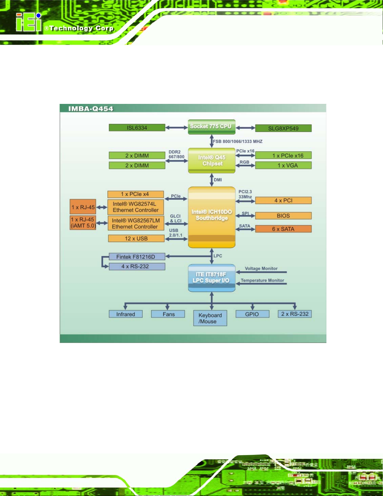
1.2 Data Flow
7Figure 1-4 shows the data flow between the system chipset, the CPU and other
components installed on the motherboard.
IMBA-Q454-R10 User Manual
Figure 1-4: Data Flow Block Diagram
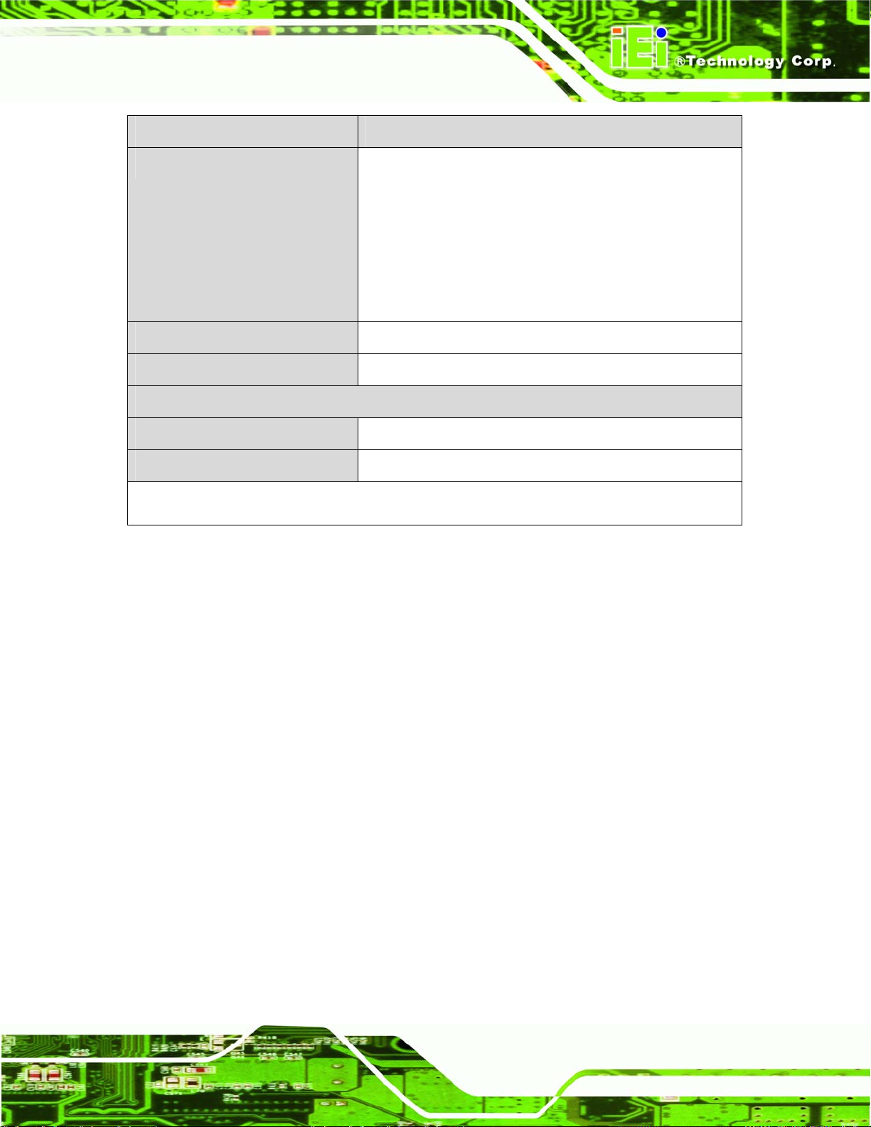
1.3 Technical Specifications:
IMBA-Q454-R10 motherboard technical specifications are listed in the table below.
Page 20
Page 21
IMBA-Q454-R10 User Manual
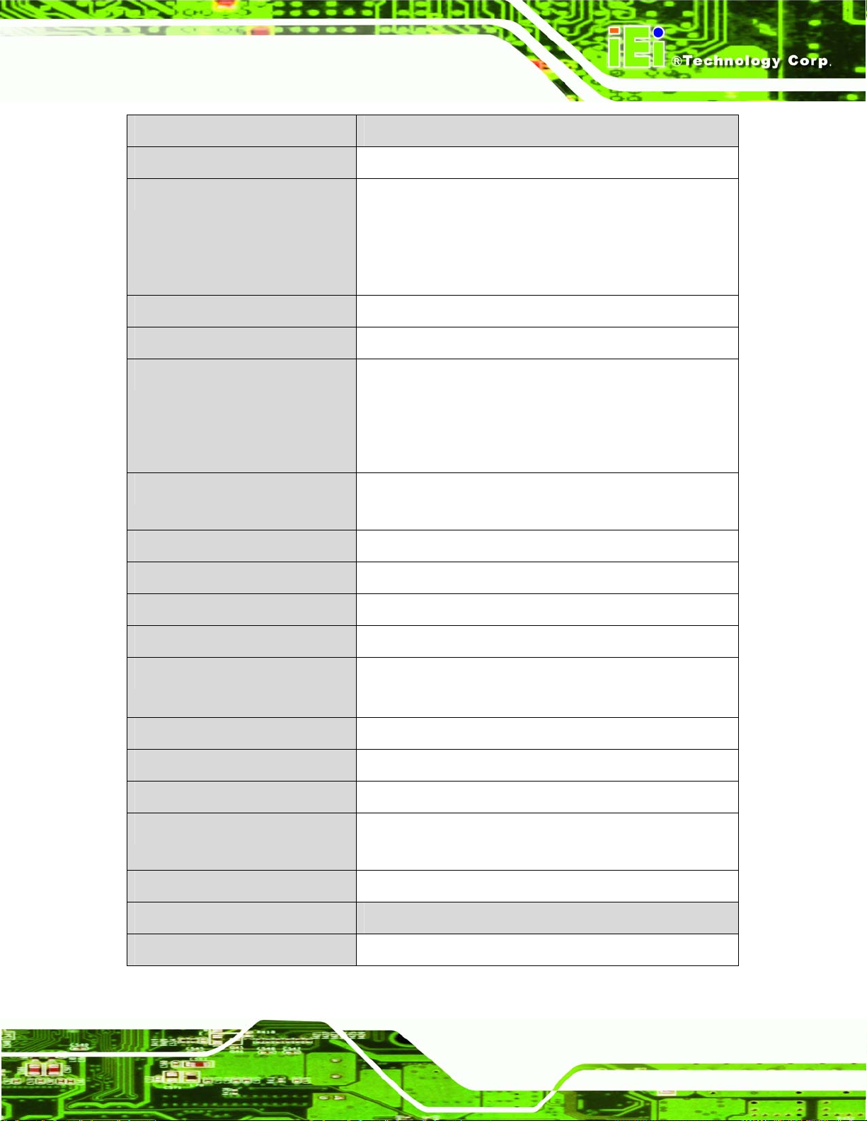
Specification/Model IMBA-Q454-R10
Form Factor
CPU Supported
Front Side Bus (FSB)
Northbridge Chipset
Integrated Graphics
Memory
Southbridge Chipset
ATX
LGA775 Intel® Core™2 Quad (Yorkfield)
LGA775 Intel® Core™2 Duo (Wolfdale and Conroe)
LGA775 Intel® Pentium® 4/D (Wolfdale and Conroe)
LGA775 Intel® Celeron® D (Conroe L)
800 MHz, 1066 MHz or 1333 MHz
Intel® Q45
350 MHz Integrated 24-bit RAMDAC
Up to 2048 x 1536 32-bit color @ 75 Hz refresh
Unified Memory Architecture (UMA) Uses up to 352 MB of
Dynamic Video Memory Technology (DVMT)
Four dual-channel 2.0 GB (max.) 667 MHz or 800 MHz
DDR2 SDRAM DIMMs (system max. 8.0 GB) supported
Intel® ICH10DO
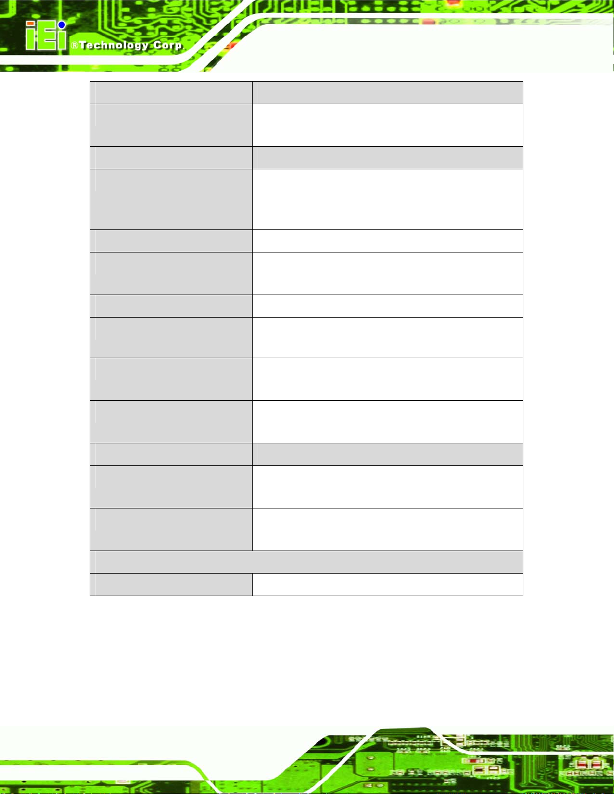
Audio
BIOS
Digital I/O
Ethernet Controllers
Trusted Platform Module
Super I/O Controller
Serial Port Controller
Real Time Clock
Watchdog Timer
Expansion
PCI
Realtek ALC888 audio codec
AMI BIOS
8-bit, 4-bit input/4-bit output
Intel® 82574L (MAC+PHY) through the PCIe x1
Intel® 82567LM (PHY) + Intel® ICH10DO (MAC)
iTPM v1.2 and above supported
ITE IT8718F
Fintek F81216
Motorola MC146818A with 256 bytes of battery-backed
RAM, 32.768 KHz crystal, 3 V battery
Software programmable supports 1~2 55 sec. system reset
Four PCI slots
Page 21
Page 22
Specification/Model IMBA-Q454-R10
IMBA-Q454-R10 User Manual
PCIe
I/O Interface Connectors
Audio Connectors
Display port
Ethernet
Keyboard/Mouse
LPT
Serial Ports
One PCIe x4 slot
One PCIe x16 slot (PCI Express Graphics interface)
One external audio jack (line-in, line-out, mic-in)
Two internal audio connectors (front panel pin header and
S/PDIF pin header)
One VGA
One RJ-45 port
One RJ-45 port with iAMT 5.0 support
One dual PS/2 port
One IEEE 1284 parallel port (supports normal, EPP and
ECP modes)
One RS-232 port
Five via internal RS-232 box pin headers
USB 2.0/1.1 ports
Storage
Floppy Disk Drives
Serial ATA
Environmental and Power Specifications
Power Supply
Four external USB ports
Eight via internal pin headers
Two 5.25” 360 KB or 1.2 MB floppy disk drives (FDD) or
3.5” 720 KB, 1.44 MB, 2.88 MB FDD.
Six independent serial ATA (SATA) channels with 3.0 Gb/s
data transfer rates
ATX supported
Page 22
Page 23
IMBA-Q454-R10 User Manual
Specification/Model IMBA-Q454-R10
Power Consumption
Operating temperature
Humidity
Physical Specifications
Dimensions
Weight GW/NW
Table 1-1: IMBA-Q454-R10 Specifications
3.3 V @ 2.64A
5 V @ 5.40A
12 V @ 0.28A
3.16 GHz E8500 Intel® Core™2 Duo CPU with 1333 MHz
FSB and 2.0 GB of 800 MHz DDR2 memory running
3DMark 2001SE
0ºC ~ 60ºC (requires cooler and silicone heat sink paste)
0% ~ 95% (non-condensing)
305mm x 244mm
1200g/600g
Page 23
Page 24
IMBA-Q454-R10 User Manual
Chapter
2
2 Unpacking
Page 24
Page 25
IMBA-Q454-R10 User Manual
2.1 Anti-static Precautions
WARNING!
Failure to take ESD precautions during the installation of the
IMBA-Q454-R10 may result in permanent damage to the
IMBA-Q454-R10 and severe injury to the user.
Electrostatic discharge (ESD) can cause serious damage to electronic components,
including the IMBA-Q454-R10. Dry climates are especially susceptible to ESD. It is
therefore critical to strictly adhere to the following anti-static precautions whenever the
IMBA-Q454-R10, or any other electrical component, is handled.
Wear an anti-static wristband - Wearing a simple anti-static wristband can
help to prevent ESD from damaging the board.
Self-grounding - Before handling the board touch any grounded conducting
material. During the time the board is handled, frequently touch any
conducting materials that are connected to the ground.
Use an anti-static pad - When configuring the IMBA-Q454-R10, place it on
an antic-static pad. This reduces the possibility of ESD damaging the
IMBA-Q454-R10.
Only handle the edges of the PCB - When handling the PCB, hold the PCB
by the edges.
2.2 Unpacking
When the IMBA-Q454-R10 is unpacked, please do the following:
Follow the anti-static precautions outlined in Section
Make sure the packing box is facing upwards so the IMBA-Q454-R10 does
not fall out of the box.
Make sure all the components shown in Section
2.1.
2.3 are present.
Page 25
Page 26
2.3 Unpacking Checklist
NOTE:
If any of the components listed in the checklist below are missing, do
not proceed with the installation. Contact the IEI reseller or vendor the
IMBA-Q454-R10 was purchased from or contact an IEI sales
representative directly by sending an email to 33sales@iei.com.tw.
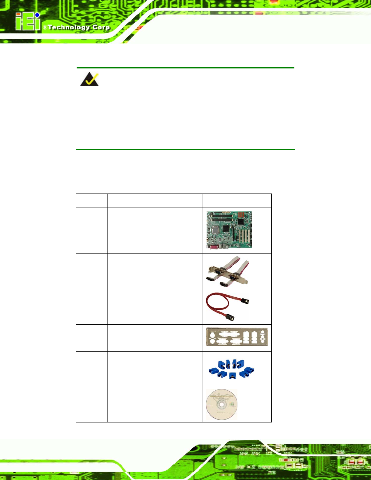
2.3.1 Package Contents
The IMBA-Q454-R10 is shipped with the following components:
Quantity Item and Part Number Image
IMBA-Q454-R10 User Manual
1 IMBA-Q454-R10
2 Dual RS-232 cable (with bracket)
(P/N: 32200-000051-RS)
6 SATA cable
(P/N: 32000-062800-RS)
1 I/O Shielding
(P/N: 45002-450903-00-RS)
1 Mini jumper pack (2.0 mm)
(P/N:33100-000079-RS)
Page 26
1 Utility CD
Page 27
IMBA-Q454-R10 User Manual
Quantity Item and Part Number Image
1 Quick Installation Guide
Table 2-1: Packing List
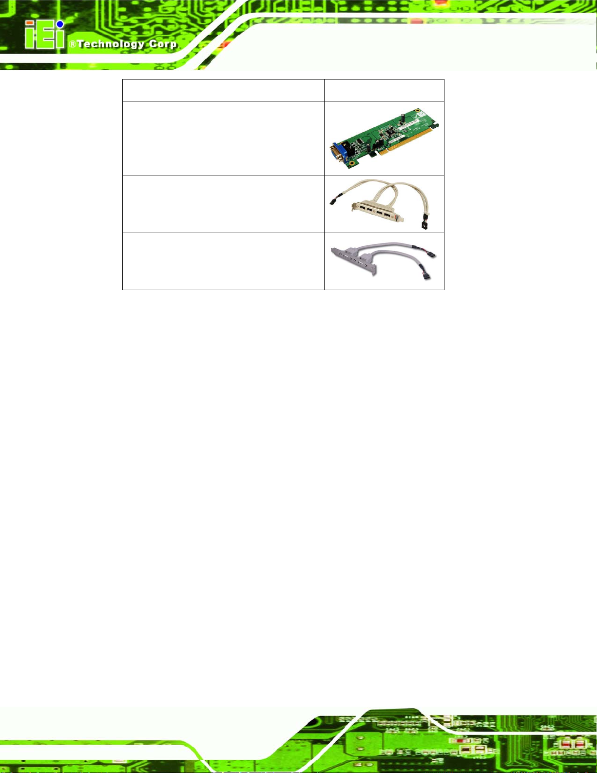
2.3.2 Optional Items
The IMBA-Q454-R10 is shipped with the following components:
Item and Part Number Image
CPU cooler
(P/N: CF-520-RS)
CPU cooler
(P/N: CF-775A-RS)
FDD cable
(P/N: 32200-000017-RS)
SATA power cable
(P/N: 32100-088600-RS)
PCIe 16X SDVO interface DVI graphic card
SDVO-100DVI-R10
Page 27
Page 28
Item and Part Number Image
PCIe 16X SDVO interface VGA graphic card
SDVO-100VGA-R10
USB cable 4-port with bracket
(P/N: CB-USB14-RS)
USB cable, Dual port with bracket
(P/N: CB-USB02-RS)
Table 2-2: Optional Items
IMBA-Q454-R10 User Manual
Page 28
Page 29
IMBA-Q454-R10 User Manual
3 Connector Pinouts
Chapter
3
Page 29
Page 30
3.1 Peripheral Interface Connectors
Section 3.1.2 shows peripheral interface connector locations. Section 3.1.2 lists all the
IMBA-Q454-R10 User Manual
peripheral interface connectors seen in Section
3.1.2.
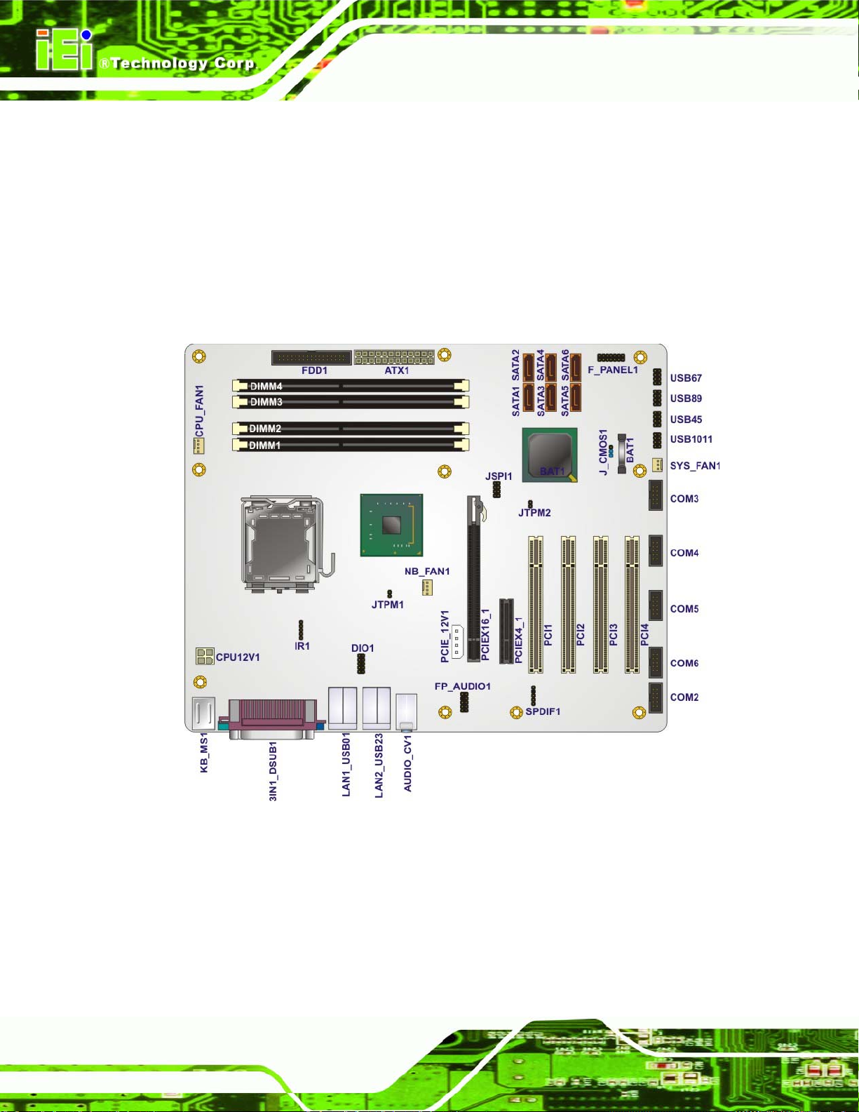
3.1.1 IMBA-Q454-R10 Layout
7Figure 3-1 shows the on-board peripheral connectors, rear panel peripheral connectors
and on-board jumpers.
Page 30
Figure 3-1: Connector and Jumper Locations
Page 31

IMBA-Q454-R10 User Manual
3.1.2 Peripheral Interface Connectors
7Table 3-1 shows a list of the peripheral interface connectors on the IMBA-Q454-R10.
Detailed descriptions of these connectors can be found below.
Connector Type Label
ATX power connector, CPU 4-pin A TX CPU12V1
ATX power connector, system 24-pin A TX ATX1
Audio connector 10-pin header FP_AUDIO1
Digital I/O connector 10-pin header DIO1
Fan connector , System 3-pin wafer SYS_FAN1
Fan connectors, CPU and
Northbridge
Floppy disk connector 34-pin box header FDD1
Front panel connector 14-pin header F_PANEL1
Infrared connector 5-pin header IR1
PCI connectors PCI slot PCI1
PCIe power connector PCIE_12V1
PCIe x16 connector PCIe x16 slot PCIEX16_1
PCIe x4 connectors PCIe x4 slot PCIEX4_1
SATA connector 7-pin SATA SATA1
4-pin wafer CPU_FAN1
NB_FAN1
PCI2
PCI3
PCI4
SATA2
SATA3
SATA4
SATA5
SATA6
Page 31
Page 32

Connector Type Label
Serial port connector 10-pin box header COM2
S/PDIF connector 5-pin header SPDIF1
SPI flash connector 8-pin header JSPI1
USB connector 10-pin header USB45
IMBA-Q454-R10 User Manual
COM3
COM4
COM5
COM6
USB67
USB89
USB1011
Table 3-1: Peripheral Interface Connectors
3.1.3 External Interface Panel Connectors
7Table 3-2 lists the rear panel connectors on the IMBA-Q454-R10. Detailed descriptions of
these connectors can be found in Section
Connector Type Label
Audio connectors Audio jacks AUDIO_CV1
Keyboard and mouse connectors Dual PS/2 KB_MS1
LAN Connector RJ-45 LAN1_USB01
Parallel port connector DB-25 connector 3IN1_DSUB1
RS-232 serial port connector D-sub 9-pin male 3IN1_DSUB1
USB 2.0 ports Dual USB ports LAN1_USB01
3.1.
LAN2_USB23
LAN2_USB23
Page 32
VGA port connector 15-pin female VGA 3IN1_DSUB1
Table 3-2: Rear Panel Connectors
Page 33

IMBA-Q454-R10 User Manual
3.2 Internal Peripheral Connectors
Internal peripheral connectors are found on the motherboard and are only accessible
when the motherboard is outside of the chassis. T his se ction h as complet e d esc ription s of
all the internal, peripheral connectors on the IMBA-Q454-R10.
3.2.1 ATX CPU Power Connector
CN Label: CPU12V1
CN Type:
CN Location:
CN Pinouts:
The 4-pin ATX power connector is connected to an ATX power supply.
Figure 3-2: ATX Power Connector Location
4-pin ATX power connector (1x4)
See 7Figure 3-2
See 7Table 3-3
PIN NO. DESCRIPTION
1 GND
2 GND
3 +12 V
4 +12 V
Table 3-3: ATX Power Connector Pinouts
Page 33
Page 34

3.2.2 ATX Power Connector
CN Label: ATX1
IMBA-Q454-R10 User Manual
CN Type:
CN Location:
CN Pinouts:
24-pin A TX (2x24)
See 7Figure 3-3
See 7Table 3-4
The ATX connector is connected to an external ATX power supply. Power is provided to
the system, from the power supply through this connector.
Page 34
Figure 3-3: ATX Power Connector Pinout Locations
PIN NO. DESCRIPTION PIN NO. DESCRIPTION
1 +3.3 V 13 +3.3 V
2 +3.3 V 14 -12 V
3 GND 15 GND
4 +5 V 16 PS-ON
5 GND 17 GND
6 +5 V 18 GND
7 GND 19 GND
8 NC 20 NC
Page 35

IMBA-Q454-R10 User Manual
PIN NO. DESCRIPTION PIN NO. DESCRIPTION
9 +VCC5SB 21 +5 V
10 +12 V 22 +5 V
11 +12 V 23 +5 V
12 +3.3 V 24 GND
Table 3-4: ATX Power Connector Pinouts
3.2.3 Audio Connector
CN Label: FP_AUDIO1
CN Type:
CN Location:
CN Pinouts:
10-pin header
See 7Figure 3-4
See 7Table 3-5
The 10-pin audio connector is connected to external audio devices including speakers a nd
microphones for the input and output of audio signals to and from the system.
Figure 3-4: Audio Connector Pinouts
Page 35
Page 36

IMBA-Q454-R10 User Manual
PIN NO. DESCRIPTION PIN NO. DESCRIPTION
1
3
5
7
9
Microphone left
Microphone right
Line out right
SENSE_SEND
Line out left
2
4
6
8
10
GND
PRESENCE
GND
N/C
GND
Table 3-5: Audio Connector Pinouts
3.2.4 Digital I/O Connector
CN Label: DIO1
CN Type:
CN Location:
CN Pinouts:
The digital input/output connector is managed through a Super I/O chip. The Digital I/O
connector pins are user programmable.
10-pin header (2x5)
See 8Figure 3-5
See 8Table 3-6
Figure 3-5: Digital I/O Connector Locations
PIN NO. DESCRIPTION PIN NO. DESCRIPTION
1 GND 2 VCC
3 Output 3 4 Output 2
Page 36
Page 37

IMBA-Q454-R10 User Manual
PIN NO. DESCRIPTION PIN NO. DESCRIPTION
5 Output 1 6 Output 0
7 Input 3 8 Input 2
9 Input 1 10 Input 0
Table 3-6: Digital I/O Connector Pinouts
3.2.5 Fan Connectors, CPU and Northbridge
CN Label: CPU_FAN1, NB_FAN1
CN Type:
CN Location:
CN Pinouts:
The cooling fan connector provides a 12 V, 500mA current to a CPU cooling fan. The
connector has a "rotation" pin to get rotation signals from fans and notify the system so the
system BIOS can recognize the fan speed. Please note that only specified fans can issue
the rotation signals.
4-pin header
See 8Figure 3-6
See 8Table 3-7
Figure 3-6: CPU and Northbridge Fan Connectors Location
Page 37
Page 38

PIN NO. DESCRIPTION
1 GND
2 +12 VCC
3 Rotation Signal
4 Control
Table 3-7: CPU Fan Connector Pinouts
3.2.6 Fan Connector, System
CN Label: SYS_FAN1
IMBA-Q454-R10 User Manual
CN Type:
CN Location:
CN Pinouts:
3-pin header
See 8Figure 3-7
See 8Table 3-8
The cooling fan connector provides a 12 V, 500mA current to a system cooling fan. The
connector has a "rotation" pin to get rotation signals from fans and notify the system so the
system BIOS can recognize the fan speed. Please note that only specified fans can issue
the rotation signals.
Page 38
Figure 3-7: System Fan Connector Location
PIN NO. DESCRIPTION
1 GND
2 +12 V
Page 39

IMBA-Q454-R10 User Manual
PIN NO. DESCRIPTION
3 Fan Speed Detect
Table 3-8: System Fan Connector Pinouts
3.2.7 Floppy Disk Connector
CN Label: FDD1
CN Type:
CN Location:
CN Pinouts:
The floppy disk connector is connected to a floppy disk drive. The IMBA-Q454-R10
supports the following floppy disk drives:
360 KB
720 KB
1.2 MB
1.44 MB
2.88 MB
34-pin header (2x17)
See 8Figure 3-8
See 8Table 3-9
Figure 3-8: 34-pin FDD Connector Location
Page 39
Page 40

IMBA-Q454-R10 User Manual
PIN NO. DESCRIPTION PIN NO. DESCRIPTION
1 GND 2 REDUCE WRITE
3 GND 4 N/C
5 N/C 6 N/C
7 GND 8 INDEX#
9 GND 10 MOTOR ENABLE A#
11 GND 12 DRIVE SELECT B#
13 GND 14 DRIVE SELECT A#
15 GND 16 MOTOR ENABLE B#
17 GND 18 DIRECTION#
19 GND 20 STEP#
21 GND 22 WRITE DATA#
23 GND 24 WRITE GATE#
25 GND 26 TRACK 0#
27 GND 28 WRITE PROTECT#
29 GND 30 READ DATA#
31 GND 32 SIDE 1 SELECT#
33 GND 34 DISK CHANGE#
Table 3-9: 34-pin FDD Connector Pinouts
3.2.8 Front Panel Connector
CN Label: F_PANEL1
CN Type:
CN Location:
CN Pinouts:
The front panel connector connects to external switches and indicators to monitor and
control the motherboard. These indicators and switches include:
14-pin header (2x7)
See 8Figure 3-9
See 8Table 3-10
Page 40
Power button
Reset button
Power LED
Page 41

IMBA-Q454-R10 User Manual
HDD LED
Speaker
Figure 3-9: Front Panel Connector Pinout Locations
FUNCTION PIN DESCRIPTION FUNCTION PIN DESCRIPTION
Power LED 1 LED +5 V Speaker 2 +5 V
3 N/C 4 N/C
5 Ground 6 N/C
Power Button 7 Power Button+ 8 Speaker
9 Power Button- Reset 10 N/C
HDD LED 11 +5 V 12 RESET 13 HDLED- 14 GND
Table 3-10: Front Panel Connector Pinouts
3.2.9 Infrared Interface Connector (5-pin)
CN Label: IR1
CN Type:
5-pin header (1x5)
CN Location:
CN Pinouts:
See 8Figure 3-10
See 8Table 3-11
Page 41
Page 42

IMBA-Q454-R10 User Manual
The infrared interface connector supports both Serial Infrared (SIR) and Amplitude Shift
Key Infrared (ASKIR) interfaces.
Figure 3-10: Infrared Connector Pinout Locations
PIN NO. DESCRIPTION
1 VCC
2 NC
3 IR-RX
4 GND
5 IR-TX
Table 3-11: Infrared Connector Pinouts
3.2.10 PCI Express x4 Slot
CN Label: PCIE4X_1
CN Type:
CN Location:
CN Pinouts:
PCIe x4 expansion devices can be inserted into the PCIe x4 slots.
PCIe x4 slots
See 8Figure 3-11
See 8Table 3-12
Page 42
Page 43

IMBA-Q454-R10 User Manual
Figure 3-11: PCIe x4 Connector Locations
SIDE A SIDE B
PIN NAME PIN NAME PIN NAME PIN NAME
A1 N/C A2 +12 V B1 +12 V B2 +12 V
A3 +12 V A4 GND B3 +12 V B4 GND
A5 N/C A6 N/C B5 SMCLK B6 SMDAT
A7 N/C A8 N/C B7 GND B8 +3.3 V
A9 +3.3 V A10 +3.3 V B9 N/C B10 3.3 V
A11 RESET A12 GND B11 WAKE# B12 N/C
A13 REFCLK+ A14 REFCLK- B13 GND B14 HSOp(0)
A15 GND A16 HSIp(0) B15 HSOn(0) B16 GND
A17 HSIn(0) A18 GND B17 N/C B18 GND
A19 N/C A20 GND B19 HSOp(1) B20 HSOn(1)
A21 HSIp(1) A22 HSIn(1) B21 GND B22 GND
A23 GND A24 GND B23 HSOp(2) B24 HSOn(2)
A25 HSIp(2) A26 HSIn(2 B25 GND B26 GND
A27 GND A28 GND B27 HSOp(3) B28 HSOn(3)
Page 43
Page 44

SIDE A SIDE B
A29 HSIp(3) A30 HSIn(3) B29 GND B30 N/C
A31 GND A32 N/C B31 N/C B32 GND
IMBA-Q454-R10 User Manual
Table 3-12: PCIe x4 Pinouts
3.2.11 PCI Express x16 Slot
CN Label: PCIEX16_1
CN Type:
CN Location:
CN Pinouts:
PCIe x16 slot
See 8Figure 3-12
See 8Table 3-13 (Side A) 8Table 3-14 (Side B)
PCIe x16 expansion devices can be inserted into the PCIe x16 slot.
Figure 3-12: PCIe x16 Connector Location
PIN NAME PIN NAME PIN NAME PIN NAME
A1 Name A22 HSIn(1) A43 HSIp(6) A64 HSIp(11)
A2 PRSNT#1 A23 GND A44 HSIn(6) A65 HSIn(11)
A3 +12v A24 GND A45 GND A66 GND
A4 +12v A25 HSIp(2) A46 GND A67 GND
A5 GND A26 HSIn(2) A47 HSIp(7) A68 HSIp(12)
Page 44
Page 45

IMBA-Q454-R10 User Manual
PIN NAME PIN NAME PIN NAME PIN NAME
A6 JTAG2 A27 GND A48 HSIn(7) A69 HSIn(12)
A7 JTAG3 A28 GND A49 GND A70 GND
A8 JTAG4 A29 HSIp(3) A50 RSVD A71 GND
A9 JTAG5 A30 HSIn(3) A51 GND A72 HSIp(13)
A10 +3.3v A31 GND A52 HSIp(8) A73 HSIn(13)
A11 +3.3v A32 RSVD A53 HSIn(8) A74 GND
A12 PWRGD A33 RSVD A54 GND A75 GND
A13 GND A34 GND A55 GND A76 HSIp(14)
A14 REFCLK+ A35 HSIp(4) A56 HSIp(9) A77 HSIn(14)
A15 REFCLK- A36 HSIn(4) A57 HSIn(9) A78 GND
A16 GND A37 GND A58 GND A79 GND
A17 HSIp(0) A38 GND A59 GND A80 HSIp(15)
A18 HSIn(0) A39 HSIp(5) A60 HSIp(10) A81 HSIn(15)
A19 GND A40 HSIn(5) A61 HSIn(10) A82 GND
A20 RSVD A41 GND A62 GND
A21 GND A42 GND A63 GND
Table 3-13: PCIe x16 Side A Pinouts
PIN NAME PIN NAME PIN NAME PIN NAME
B1 +12v B22 GND B43 GND B64 GND
B2 +12v B23 HSOp(2) B44 GND B65 GND
B3 RSVD B24 HSOn(2) B45 HSOp(7) B66 HSOp(12)
B4 GND B25 GND B46 HSOn(7) B67 HSOn(12)
B5 SMCLK B26 GND B47 GND B68 GND
B6 SMDAT B27 HSOp(3) B48 PRSNT#2 B69 GND
B7 GND B28 HSOn(3) B49 GND B70 HSOp(13)
B8 +3.3v B29 GND B50 HSOp(8) B71 HSOn(13)
B9 JTAG1 B30 RSVD B51 HSOn(8) B72 GND
B10 3.3 Vaux B31 PRSNT#2 B52 GND B73 GND
B11 WAKE# B32 GND B53 GND B74 HSOp(14)
B12 RSVD B33 HSOp(4) B54 HSOp(9) B75 HSOn(14)
Page 45
Page 46

PIN NAME PIN NAME PIN NAME PIN NAME
B13 GND B34 HSOn(4) B55 HSOn(9) B76 GND
B14 HSOp(0) B35 GND B56 GND B77 GND
B15 HSOn(0) B36 GND B57 GND B78 HSOp(15)
B16 GND B37 HSOp(5) B58 HSOp(10) B79 HSOn(15)
B17 PRSNT#2 B38 HSOn(5) B59 HSOn(10) B80 GND
B18 GND B39 GND B60 GND B81 PRSNT#2
B19 HSOp(1) B40 GND B61 GND B82 RSVD#2
B20 HSOn(1) B41 HSOp(6) B62 HSOp(11)
B21 GND B42 HSOn(6) B63 HSOn(11)
IMBA-Q454-R10 User Manual
Table 3-14: PCIe x16 Side B Pinouts
3.2.12 PCI Slot
CN Label: PCI1, PCI2, PCI3 and PCI4
CN Type:
CN Location:
CN Pinouts:
PCI Slot
See 8Figure 3-13
See 8Table 3-15
The PCI slot enables a PCI expansion module to be connected to the board.
Page 46
Page 47

IMBA-Q454-R10 User Manual
Figure 3-13: PCI Slot Location
PIN NO. DESCRIPTION PIN NO. DESCRIPTION
A1 TRST B1 -12 V
A2 +12 V B2 TCK
A3 TMS B3 GND
A4 TDI B4 TDO
A5 +5 V B5 +5 V
A6 INTA B6 +5 V
A7 INTC B7 INTB
A8 +5 V B8 INTD
A9 RESERVED3 B9 PRSNT1
A10 +5 V B10 RESERVED1
A11 RESERVED4 B11 PRSNT2
A12 GND B12 GND
A13 GND B13 GND
Page 47
Page 48

PIN NO. DESCRIPTION PIN NO. DESCRIPTION
A14 3.3 V_AUX B14 RESERVED2
A15 RST B15 GND
A16 +5 V B16 CLK
A17 GNT B17 GND
A18 GND B18 REQ
A19 PME B19 +5 V
A20 AD30 B20 AD31
A21 +3.3 V B21 AD29
A22 AD28 B22 GND
A23 AD26 B23 AD27
A24 GND B24 AD25
A25 AD24 B25 +3.3 V
IMBA-Q454-R10 User Manual
A26 IDSEL B26 C/BE3
A27 +3.3 V B27 AD23
A28 AD22 B28 GND
A29 AD20 B29 AD21
A30 GND B30 AD19
A31 AD18 B31 +3.3 V
A32 AD16 B32 AD17
A33 +3.3 V B33 C/BE2
A34 FRAME B34 GND
A35 GND B35 IRDY
A36 TRDY B36 +3.3 V
A37 GND B37 DEVSEL
A38 STOP B38 GND
A39 +3.3 V B39 LOCK
A40 SDONE B40 PERR
A41 SBO B41 +3.3 V
Page 48
A42 GND B42 SERR
A43 PAR B43 +3.3 V
A44 AD15 B44 C/BE1
Page 49

IMBA-Q454-R10 User Manual
PIN NO. DESCRIPTION PIN NO. DESCRIPTION
A45 +3.3 V B45 AD14
A46 AD13 B46 GND
A47 AD11 B47 AD12
A48 GND B48 AD10
A49 AD9 B49 GND
A52 C/BE0 B52 AD8
A53 +3.3 V B53 AD7
A54 AD6 B54 +3.3 V
A55 AD4 B55 AD5
A56 GND B56 AD3
A57 AD2 B57 GND
A68 AD0 B68 AD1
A59 +5 V B59 +5 V
A60 REQ64 B60 ACK64
A61 +5 V B61 +5 V
A62 +5 V
B62 +5 V
Table 3-15: PCI Slot
3.2.13 SATA Drive Connectors
CN Label: SATA1, SATA2, SATA3, SATA4, SATA5 and SATA6
CN Type:
CN Location:
CN Pinouts:
The six SATA drive connectors are each connected to a first generation SATA drive. First
generation SATA drives transfer data at speeds as high as 300 MB/s. The SATA drives
can be configured in a RAID configuration.
SATA drive connectors
See 8Figure 3-14
See 8Table 3-16
Page 49
Page 50

IMBA-Q454-R10 User Manual
Figure 3-14: SATA Drive Connector Locations
PIN NO. DESCRIPTION
1 GND
2 TX+
3 TX4 GND
5 RX6 RX+
7 GND
Table 3-16: SATA Drive Connector Pinouts
3.2.14 S/PDIF Connector
CN Label: SPDIF1
CN Type:
5-pin header
Page 50
CN Location:
CN Pinouts:
See 8Figure 3-15
See 8Table 3-17
Page 51

IMBA-Q454-R10 User Manual
Use the SPDIF connector to connect digital audio devices to the system.
Figure 3-15: SPDIF Connector Pinout Locations
PIN DESCRIPTION
1 5 V audio
2 NC
3 SPDIF out
4 GND audio
5 SPDIF in
Table 3-17: SPDIF Connector Pinouts
3.2.15 Serial Port Connectors
CN Label: COM2, COM3, COM4, COM5, COM6
CN Type:
9-pin box headers (2x5)
CN Location:
CN Pinouts:
See 8Figure 3-16
See 8Table 3-18
Page 51
Page 52

IMBA-Q454-R10 User Manual
The 10-pin serial port connectors provide a RS-232 serial communications channels. The
serial port connectors can be connected to external RS-232 serial port devices.
Figure 3-16: Serial Port Connectors Pinout Locations
PIN NO. DESCRIPTION PIN NO. DESCRIPTION
1 Data Carrier Detect (DCD) 2 Receive Data (RXD)
3 Transmit Data (TXD) 4 Data Terminal Ready (DTR)
5 Ground (GND) 6 Data Set to Ready (DSR)
7 Request to Send (RTS) 8 Clear to Sent (CTS)
9 Ring Indicator (RI) 10 N/C
Table 3-18: Serial Port Connector Pinouts
3.2.16 SPI Flash Connector
CN Label: JSPI1
CN Type:
8-pin header (2x4)
Page 52
CN Location:
CN Pinouts:
See 8Figure 3-17
See 8Table 3-19
The SPI connector is for flashing the SPI BIOS.
Page 53

IMBA-Q454-R10 User Manual
Figure 3-17: SPI Flash Connector Pinouts
PIN DESCRIPTION PIN DESCRIPTION
1 VCC 2 GND
3 CS# 4 CLOCK
5 SO 6 SI
7 NC 8 NC
Table 3-19: SPI Flash Connector
3.2.17 USB Connectors
CN Label: USB45, USB67, USB89 and USB1011
CN Type:
CN Location:
CN Pinouts:
The 2x5 USB pin connectors each provide connectivity to two USB 1.1 or two USB 2.0
8-pin header (2x4)
See 8Figure 3-18
See 8Table 3-20
ports. Each USB connector can support two USB devices. Additional external USB ports
are found on the rear panel. The USB ports are used for I/O bus expansion.
Page 53
Page 54

IMBA-Q454-R10 User Manual
Figure 3-18: USB Connector Pinout Locations
PIN NO. DESCRIPTION PIN NO. DESCRIPTION
1 VCC 2 GND
3 DATA- 4 DATA+
5 DATA+ 6 DATA7 GND 8 VCC
Table 3-20: USB Port Connector Pinouts
3.3 External Interface Connectors
8Figure 3-19 shows the IMBA-Q454-R10 motherboard external interface connectors. The
IMBA-Q454-R10 on-board external interface connectors are shown in
8Figure 3-19:
Page 54
Page 55

IMBA-Q454-R10 User Manual
Figure 3-19: IMBA-Q454-R10 External Interface Connectors
3.3.1 Audio Connector
CN Label: AUDIO1
CN Type:
CN Location:
The three audio jacks on the external audio connector enable the IMBA-Q454-R10 to be
connected to external audio devices as specified below.
Line In port (Light Blue): Connects a CD-ROM, DVD player, or other audio
devices.
Line Out port (Lime): Connects to headphones or speakers.
Microphone (Pink): Connects a microphone.
3 x audio jacks
See 8Figure 3-19
Figure 3-20: Audio Connector
Page 55
Page 56

3.3.2 Ethernet Connector
CN Label: LAN1_USB01, LAN2_USB23
IMBA-Q454-R10 User Manual
CN Type:
CN Location:
CN Pinouts:
RJ-45
See 8Figure 3-19
See 8Table 3-21
A 10/100/1000 Mb/s connection can be made to a Local Area Network.
PIN DESCRIPTION PIN DESCRIPTION
1 TX+ 5 N/C
2 N/C 6 RX3 TX- 7 N/C
4 RX+ 8 N/C
Table 3-21: Ethernet Connector Pinouts
Page 56
Figure 3-21: Ethernet Connector
The RJ-45 Ethernet connector has two status LEDs, one green and one yello w. The green
LED indicates activity on the port and the yellow LED indicates the port is linked.
SPEED LED LINK LED
Status Description Status Description
GREEN ON: 100 MB
OFF: 10 MB
YELLOW ON: Linked
Flashing: Activity
Table 3-22: Connector LEDs
Page 57

IMBA-Q454-R10 User Manual
3.3.3 Keyboard and Mouse Connector
CN Label: KB_MS1
CN Type:
CN Location:
CN Pinouts:
PS/2
See 8Figure 3-19
See 8Table 3-23 and 8Figure 3-22
The IMBA-Q454-R10 has two PS/2 connectors on the mounting bracket for easy
connection to a PS/2 keyboard and PS/2 mouse.
Figure 3-22: PS/2 Connector
PIN NO. DESCRIPTION PIN NO. DESCRIPTION
1 KEYBOARD DATA 7 MOUSE DATA
2 NC 8 NC
3 GND 9 GND
4 +5 V 10 +5 V
5 KEYBOARD CLOCK 11 MOUSE DATA
6 NC 12 NC
Table 3-23: PS/2 Connectors
Page 57
Page 58

3.3.4 Parallel Port Connector
CN Label: LPT
IMBA-Q454-R10 User Manual
CN Type:
CN Location:
CN Pinouts:
26-pin box header
See 8Figure 3-19
See 8Table 3-24
The 26-pin parallel port connector connects to a parallel port connector interface or some
other parallel port device such as a printer.
PIN NO. DESCRIPTION PIN NO. DESCRIPTION
1 STROBE# 14 AUTO FORM FEED #
2 DATA 0 15 ERROR#
3 DATA 1 16 INITIALIZE
4 DATA 2 17 PRINTER SELECT LN#
5 DATA 3 18 GROUND
6 DATA 4 19 GROUND
7 DATA 5 20 GROUND
8 DATA 6 21 GROUND
9 DATA 7 22 GROUND
10 ACKNOWLEDGE 23 GROUND
11 BUSY 24 GROUND
12 PAPER EMPTY 25 GROUND
13 PRINTER SELECT
Table 3-24: Parallel Port Connector Pinouts
Figure 3-23: Parallel Port Connector Location
Page 58
Page 59

IMBA-Q454-R10 User Manual
3.3.5 Serial Port Connector
CN Label: COM1
CN Type:
CN Location:
CN Pinouts:
The RS-232 serial connector provides serial connection in the RS-232 mode.
PIN DESCRIPTION PIN DESCRIPTION
1 DCD# 6 DSR#
2 RxD 7 RTS#
3 TxD 8 CTS#
4 DTR# 9 RI#
5 GND
Table 3-25: Serial Port Pinouts
DB-9 connector
See 8Figure 3-19
See 8Table 3-25 and 8Figure 3-24
Figure 3-24: Serial Port Pinout Locations
3.3.6 USB Ports
CN Label: LAN1_USB01 and LAN2_USB23
CN Type:
CN Location:
CN Pinouts:
USB Combo ports
See 8Figure 3-19
See 8Table 3-26
Page 59
Page 60

The USB combo port and LAN/USB combo port provides connectivity to five additional
USB devices. USB devices connect directly to the USB connectors on the rear panel.
PIN DESCRIPTION PIN DESCRIPTION
1 +5 V 5 +5 V
2 D- 6 D3 D+ 7 D+
4 GND 8 GND
Table 3-26: USB Connector Pinouts
3.3.7 VGA Connector
CN Label: VGA
IMBA-Q454-R10 User Manual
CN Type:
CN Location:
CN Pinouts:
D-sub 15-pin female connector
See 8Figure 3-19
See 8Figure 3-25 and 8Table 3-27
The standard 15-pin female VGA connector connects to a CRT or LCD monitor.
PIN DESCRIPTION PIN DESCRIPTION PIN DESCRIPTION
1 RED 6 GROUND 11 NC
2 GREEN 7 GROUND 12 SDA
3 BLUE 8 GROUND 13 HSYNC
4 +5V 9 NC 14 VSYNC
5 GROUND 10 GROUND 15 SCL
Table 3-27: VGA Connector Pinouts
Page 60
Figure 3-25: VGA Connector
Page 61

IMBA-Q454-R10 User Manual
Chapter
4
4 Installation
Page 61
Page 62

4.1 Anti-static Precautions
WARNING:
Failure to take ESD precautions during the installation of the
IMBA-Q454-R10 may result in permanent damage to IMBA-Q454-R10
and severe injury to the user.
Electrostatic discharge (ESD) can cause serious damage to electronic components,
including the IMBA-Q454-R10. Dry climates are especially susceptible to ESD. It is
therefore critical to strictly adhere to the following anti-static precautions whenever the
IMBA-Q454-R10, or any other electrical component, is handled.
Wear an anti-static wristband: - Wearing a simple anti-static wristband can
IMBA-Q454-R10 User Manual
help to prevent ESD from damaging the board.
Self-grounding:- Before handling the board touch any grounded conducting
material. During the time the board is handled, frequently touch any
conducting materials that are connected to the ground.
Use an anti-static pad: When configuring the IMBA-Q454-R10, place it on an
antic-static pad. This reduces the possibility of ESD damaging the
IMBA-Q454-R10.
Only handle the edges of the PCB:-: When handling the PCB, hold the PCB
by the edges.
Page 62
Page 63

IMBA-Q454-R10 User Manual
4.2 Installation Considerations
NOTE:
The following installation notices and installation considerations should
be read and understood before the IMBA-Q454-R10 is installed. All
installation notices pertaining to the installation of IMBA-Q454-R10
should be strictly adhered to. Failing to adhere to these precautions
may lead to severe damage of the IMBA-Q454-R10 and injury to the
person installing the motherboard.
4.2.1 Installation Notices
WARNING:
The installation instructions described in this manual should be
carefully followed in order to prevent damage to the IMBA-Q454-R10,
IMBA-Q454-R10 components and injury to the user.
Before and during the installation please DO the following:
Read the user manual:
o The user manual provides a complete description of the IMBA-Q454-R10
installation instructions and configuration options.
Wear an electrostatic discharge cuff (ESD):
o Electronic components are easily damaged by ESD. Wearing an ESD cuff
removes ESD from the body and helps prevent ESD damage.
Place the IMBA-Q454-R10 on an antistatic pad:
o When installing or configuring the motherboard, place it on an antistatic
pad. This helps to prevent potential ESD damage.
Turn all power to the IMBA-Q454-R10 off:
Page 63
Page 64

IMBA-Q454-R10 User Manual
o When working with the IMBA-Q454-R10, make sure that it is
disconnected from all power supplies and that no electricity is being fed
into the system.
Before and during the installation of the IMBA-Q454-R10 DO NOT:
Remove any of the stickers on the PCB board. These stickers are required for
warranty validation.
Use the product before verifying all the cables and power connectors are
properly connected.
Allow screws to come in contact with the PCB circuit, connector pins, or its
components.
4.3 CPU, CPU Cooling Kit and DIMM Installation
WARNING:
A CPU should never be turned on without the specified cooling kit
being installed. If the cooling kit (heat sink and fan) is not properly
installed and the system turned on, permanent damage to the CPU,
IMBA-Q454-R10 and other electronic components attached to the
system may be incurred. Running a CPU without a cooling kit may also
result in injury to the user.
The CPU, CPU cooling kit and DIMM are the most critical components of the
IMBA-Q454-R10. If one of these component is not installed the IMBA-Q454-R10 cannot
run.
4.3.1 Socket LGA775 CPU Installation
NOTE:
Page 64
To enable Hyper-Threading Technology, the CPU, chipset and
operating system must all support Hyper-Threading Technology.
Page 65

IMBA-Q454-R10 User Manual
WARNING:
CPUs are expensive and sensitive components. When installing the
CPU please be careful not to damage it in anyway. Make sure the CPU
is installed properly and ensure the correct cooling kit is properly
installed.
The LGA775 socket is shown in 8Figure 4-1.
Figure 4-1: Intel LGA775 Socket
To install a socket LGA775 CPU onto the IMBA-Q454-R10, follow the steps below:
WARNING:
When handling the CPU, only hold it on the sides. DO NOT touch the
pins at the bottom of the CPU.
Step 1: Remove the protective cover. Remove the black protective cover by prying it
off the load plate. To remove the protective cover, loca te the “REMOVE” sign
and use your fingernail to pry the protective cover off. See
8Figure 4-2.
Page 65
Page 66

IMBA-Q454-R10 User Manual
Figure 4-2: Remove the CPU Socket Protective Shield
Step 2: Open the socket. Disengage the load lever by pressing the lever down and
slightly outward to clear the retention tab. Rotate the load lever to a fully open
position. Then rotate the load plate towards the opposite direction.
8Figure 4-3.
See
Figure 4-3: Open the CPU Socket Load Plate
Step 3: Inspect the CPU socket Make sure there are no bent pins an d make sure the
socket contacts are free of foreign material. If any debris is found, remove it with
compressed air.
Page 66
Step 4: Orientate the CPU properly. Make sure the IHS (Integrated Heat Sink) side is
facing upward.
Page 67

IMBA-Q454-R10 User Manual
Step 5: Correctly position the CPU. Match the Pin 1 mark with the cut edge on the
CPU socket.
Step 6: Align the CPU pins. Locate pin 1 and the two orientation notches on the CPU.
Carefully match the two orientation notches on the CPU with the socket
alignment keys.
Step 7: Insert the CPU. Gently insert the CPU into the socket. If the CPU pins are
properly aligned, the CPU should slide into the CPU socket smoothly.
8Figure 4-4.
See
Figure 4-4: Insert the Socket LGA775 CPU
Step 8: Close the CPU socket. Close the load plate and engage the load lever by
pushing it back to its original position. Secure the load lever under the retention
tab on the side of CPU socket.
Step 9: Connect the CPU 12 V cable to the 12 After the cooling kit is installed connect
the CPU cable to the CPU 12 V power connector. Step 0:
Page 67
Page 68

IMBA-Q454-R10 User Manual
4.3.2 Socket LGA775 CF-520 Cooling Kit Installation
WARNING:
It is strongly recommended that you DO NOT use the original heat
sink and cooler provided by Intel on the IMBA-Q454-R10.
The cooling kit includes a support bracket that is combined with the
heat sink mounted on the CPU to counterweigh and balance the load
on both sides of the PCB.
Figure 4-5: Cooling Kit
A Socket LGA775 CPU cooling kit shown in
cooling kit comprises a CPU heat sink and a cooling fan.
8Figure 4-5 can be purchased separately. The
WARNING:
Do not wipe off (accidentally or otherwise) the pre-sprayed layer of
thermal paste on the bottom of the heat sink. The thermal paste
between the CPU and the heat sink is important for optimum heat
dissipation.
To install the cooling kit, follow the instructions below.
Step 1: Place the cooling kit onto the socket LGA775 CPU. Make sure the CPU
cable can be properly routed when the cooling kit is installed.
Page 68
Page 69

IMBA-Q454-R10 User Manual
Step 2: Properly align the cooling kit. Make sure the four spring screw fasteners can
pass through the pre-drilled holes on the PCB.
Step 3: Mount the cooling kit. Gently place the cooling kit on top of the CPU. Make
sure the four threaded screws on the corners of the cooling kit properly pass
through the predrilled holes on the bottom of the PCB.
Step 4: Secure the cooling kit. From the solder side of the PCB, align the support
bracket to the screw threads on heat sink that were inserted through the PCB
holes. (See
8Figure 4-6)
Figure 4-6: Securing the Heat sink to the PCB Board
Step 5: Tighten the screws. Use a screwdriver to tighten the four screws. Tighten each
nut a few turns at a time and do not over-tighten the screws.
Step 6: Connect the fan cable. Connect the cooling kit fan cable to the fan connector
on the IMBA-Q454-R10. Carefully route the cable and avoid heat generating
chips and fan blades. Step 0:
Page 69
Page 70

4.3.3 DIMM Installation
WARNING:
Using incorrectly specified memory modules may cause permanent
damage the IMBA-Q454-R10. Please make sure the memory modules
comply with the recommended memory specifications.
WARNING:
1) Before removing the DDR2 DRAM module, make sure the AC power
supply is completely turned off. Incorrect usage may cause permanent
damage to the IMBA-Q454 or the DRAM module because the
IMBA-Q454-R10 User Manual
IMBA-Q454 supports the iAMT feature which provides power to the
DRAM module when the IMBA-Q454 is off.
2) Do not disconnect the ATX connector when the IMBA-Q454 power is
on. Please make sure to switch off the ATX power supply prior to
disconnecting the ATX connector. Incorrect usage may cause
permanent damage to the IMBA-Q454.
3) If the IMBA-Q454 fails to boot due to improper usage, please clear
the CMOS by disconnecting the battery from the connector.
To install a DIMM, please follow the steps below and refer to 8Figure 4-7.
Page 70
Page 71

IMBA-Q454-R10 User Manual
Figure 4-7: Installing a DIMM
Step 1: Open the DIMM socket handles. The DIMM socket has two handles that
secure the DIMM into the socket. Before the DIMM can be inserted into the
socket, the handles must be opened. See
8Figure 4-7.
Step 2: Align the DIMM with the socket. The DIMM must be oriented in such a way
that the notch in the middle of the DIMM must be aligned with the plastic bridge
in the socket. See
8Figure 4-7.
Step 3: Insert the DIMM. Once properly aligned, the DIMM can be inserted into the
socket. As the DIMM is inserted, the white handles on the side of the socket will
close automatically and secure the DIMM to the socket. See
8Figure 4-7.
Step 4: Removing a DIMM. To remove a DIMM, push both handles outward. The
memory module is ejected by a mechanism in the socket.Step 0:
Page 71
Page 72

4.4 Jumper Settings
NOTE:
A jumper is a metal bridge that is
used to close an electrical circuit. It
consists of two metal pins and a small
metal clip (often protected by a plastic
IMBA-Q454-R10 User Manual
cover) that slides over the pins to
connect them. To CLOSE/SHORT a
jumper means connecting the pins of
the jumper with the plastic clip and to
OPEN a jumper means removing the plastic clip from a jumper.
Before the IMBA-Q454-R10 is installed in the system, the jumpers must be set in
accordance with the desired configuration. The jumpers on the IMBA-Q454-R10 are listed
in
8Table 4-1.
Description Label Type
Clear CMOS J_CMOS1 3-pin header
iTPM setup jumpers JTPM1
JTPM2
Table 4-1: Jumpers
Jumper
2-pin header
4.4.1 Clear CMOS Jumper
Jumper Label: J_CMOS1
Jumper Type:
Jumper Settings:
Jumper Location:
If the IMBA-Q454-R10 fails to boot due to improper BIOS settings, the clear CMOS jumper
clears the CMOS data and resets the system BIOS information. To do this, use the jumper
Page 72
3-pin header
See 8Table 4-2
See 8Figure 4-8
Page 73

IMBA-Q454-R10 User Manual
cap to close pins 2 and 3 for a few seconds then reinstall the jumper clip back to pins 1
and 2.
If the “CMOS Settings Wrong” message is displayed during the boot up process, the fault
may be corrected by pressing the F1 to enter the CMOS Setup menu. Do one of the
following:
Enter the correct CMOS setting
Load Optimal Defaults
Load Failsafe Defaults.
After having done one of the above, save the changes and exit the CMOS Setup menu.
The clear CMOS jumper settings are shown in
AT Power Select Description
Short 1 - 2 Keep CMOS Setup Default
Short 2 - 3 Clear CMOS Setup
8Table 4-2.
Table 4-2: Clear CMOS Jumper Settings
The location of the clear CMOS jumper is shown in 8Figure 4-8 below.
Figure 4-8: Clear CMOS Jumper
Page 73
Page 74

4.4.2 iTPM Setup Jumper
Jumper Label: JTPM1 and JTPM2
IMBA-Q454-R10 User Manual
Jumper Type:
Jumper Settings:
Jumper Location:
The iTPM setup jumper settings are shown in
2-pin headers
See 8Table 4-2
See 8Figure 4-8
8Table 4-2. Close pins 1 and 2 on both
JTPM1 and JTPM2 to enable iTPM. All other settings disable iTPM.
AT Power Select Description
Open 1 - 2 Disable iTPM Default
Short 1 - 2 Enable iTPM
Table 4-3: iTPM Setup Jumper Settings
The location of the clear CMOS jumper is shown in 8Figure 4-8 below.
Figure 4-9: iTPM Setup Jumper Locations
4.5 Chassis Installation
To install the IMBA-Q454-R10 motherboard into the chassis please refer to the reference
material that came with the chassis.
Page 74
Page 75

IMBA-Q454-R10 User Manual
4.5.1 Airflow
WARNING:
Airflow is critical to the cooling of the CPU and other onboard
components. The chassis in which the IMBA-Q454-R10 must have air
vents to allow cool air to move into the system and hot air to move out.
The IMBA-Q454-R10 must be installed in a chassis with ventilation holes on the sides
allowing airflow to travel through the heat sink surface. In a system with an individual
power supply unit, the cooling fan of a power supply can also help generate airflow
through the board surface.
4.5.2 Dual RS-232 Cable with Slot Bracket
The dual RS-232 cable slot connector consists of two connectors attached to two
independent cables. Each cable is then attached to a D-sub 9 male connector that is
mounted onto a slot. To install the dual RS-232 cable, please follow the steps below.
Step 1: Locate the connectors. The locations of the RS-232 connectors are sho wn in
Chapter 3.
Step 2: Insert the cable connectors. Insert one connector into each serial port box
headers. See
the connector can only be installed in one direction.
8Figure 4-10. A key on the front of the cable connectors ensures
Page 75
Page 76

IMBA-Q454-R10 User Manual
Figure 4-10: Dual RS-232 Cable Installation
Step 3: Secure the bracket. The dual RS-232 connector has two D-sub 9 male
connectors secured on a bracket. To secure the bracket to the chassis please
refer to the reference material that came with the chassisStep 0:
4.5.3 Single RS-232 Cable with Slot Bracket
The single RS-232 cable consists of one serial port connectors attached to a serial
communications cable that is then attached to a D-sub 9 male connector that is mounted
onto a bracket. To install the single RS-232 cable, please follow the steps below.
Step 1: Locate the connector. The location of the RS-232 connector is shown in
Chapter 3.
Step 2: Insert the cable connector. Insert the connector into the serial port box header .
8Figure 4-11. A key on the front of the cable connectors ensures the
See
Page 76
connector can only be installed in one direction.
Page 77

IMBA-Q454-R10 User Manual
Figure 4-11: Single RS-232 Cable Installation
Step 3: Secure the bracket. The single RS-232 connector has one D-sub 9 male
connector secured to a bracket. To secure the bracket to the chassis please
refer to the reference material that came with the chassisStep 0:
4.5.4 SATA Drive Connection
The IMBA-Q454-R10 is shipped with two SATA drive cables and one SATA drive power
cable. To connect the SATA drives to the connectors, please follow the steps below.
Step 1: Locate the connectors. The locations of the SATA drive connectors are shown
in Chapter 3.
Step 2: Insert the cable connector. Press the clip on the connector at the end of the
SATA cable and insert the cabl e connector into the on-board SATA drive
connector. See
8Figure 4-12.
Page 77
Page 78

IMBA-Q454-R10 User Manual
Figure 4-12: SATA Drive Cable Connection
Step 3: Connect the cable to the SATA disk. Connect the connector on the other end
of the cable to the connector at the back of the SATA drive. See
8Figure 4-13.
NOTE:
The SATA power cable is an optional item that must be purchased
separately
Step 4: Connect the SATA power cable. Connect the SATA power connector to the
back of the SATA drive. See
8Figure 4-13. Step 0:
Page 78
Page 79

IMBA-Q454-R10 User Manual
Figure 4-13: SATA Power Drive Connection
4.5.5 USB Cable (Dual Port) with Slot Bracket
The IMBA-Q454-R10 is shipped with a dual port USB 2.0 cable. To connect the USB
cable connector, please follow the steps below.
Step 1: Locate the connectors. The locations of the USB connectors are shown in
Chapter 3.
WARNING:
If the USB pins are not properly aligned, the USB device can burn out.
Step 2: Align the connectors. The cable has two connectors. Correctly align pin 1on
each cable connector with pin 1 on the IMBA-Q454-R10 USB connector.
Page 79
Page 80

Step 3: Insert the cable connectors. Once the cable connectors are properly aligned
with the USB connectors on the IMBA-Q454-R10, connect the cable connectors
IMBA-Q454-R10 User Manual
to the on-board connectors. See
8Figure 4-14.
Figure 4-14: Dual USB Cable Connection
Step 4: Attach the bracket to the chassis. The USB 2.0 connectors are attached to a
bracket. To secure the bracket to the chassis please refer to the installation
instructions that came with the chassis.Step 0:
4.5.6 USB Cable (Four Port)
Four port USB 2.0 cables can be separately purchased from IEI. To install a four port USB
cable onto the IMBA-Q454-R10, please follow the steps below.
Page 80
Page 81

IMBA-Q454-R10 User Manual
Step 1: Locate the connectors. The locations of the USB connectors are shown in
Chapter 4.
WARNING:
If the USB pins are not properly aligned, the USB device can burn out.
Step 2: Align the connectors. Each cable has two connectors. Correctly align pin 1on
each cable connector with pin 1 on the IMBA-Q454-R10 USB connectors.
Step 3: Insert the cable connectors. Once the cable connectors are properly aligned
with the USB connectors on the IMBA-Q454-R10, connect the cable connectors
to the on-board connectors. See
Figure 4-15: Four Port USB Cable Connection
Step 4: Attach the bracket to the chassis. The USB 2.0 connectors are attached to a
8Figure 4-14.
bracket. To secure the bracket to the chassis please refer to the installation
instructions that came with the chassis.Step 0:
Page 81
Page 82

IMBA-Q454-R10 User Manual
4.6 External Peripheral Interface Connection
The following external peripheral devices can be connected to the external peripheral
interface connectors.
Keyboard and mouse
Serial port devices
VGA screens
Parallel port devices
Ethernet connection
USB devices
Audio devices
To install these devices, connect the corresponding cable connector from the actual
device to the corresponding IMBA-Q454-R10 external peripheral interface connector
making sure the pins are properly aligned.
4.6.1 Keyboard and Mouse
The IMBA-Q454-R10 has a dual PS/2 connector on the external peripheral interface panel.
The dual PS/2 connector is used to connect to a keyboard and mouse to the system.
Follow the steps below to connect a keyboard and mouse to the IMBA-Q454-R10.
Step 1: Locate the dual PS/2 connector. The location of the dual PS/2 connector is
shown in Chapter 3.
Step 2: Insert the keyboard/mouse connector. Insert a PS/2 keyboard or mouse
connector into the appropriate PS/2 connector on the external peripheral
interface connector . See
8Figure 4-16. Step 0:
Page 82
Page 83

IMBA-Q454-R10 User Manual
Figure 4-16: PS/2 Keyboard/Mouse Connector
4.6.2 LAN
There are two external RJ-45 LAN connectors. The RJ-45 connectors enable connection
to an external network. To connect a LAN cable with an RJ-45 connector, please follow
the instructions below.
Step 1: Locate the RJ-45 connectors. The locations of the USB connecto rs are shown
in Chapter 4.
Step 2: Align the connectors. Align the RJ-45 connector on the LAN cable with one of
the RJ-45 connectors on the IMBA-Q454-R10. See
8Figure 4-17.
Page 83
Page 84

Figure 4-17: LAN Connection
IMBA-Q454-R10 User Manual
Step 3: Insert the LAN cable RJ-45 connector. Once aligned, gently insert the LAN
cable RJ-45 connector into the on-board RJ-45 connector. Step 0:
4.6.3 Parallel Device Connection
The IMBA-Q454-R10 has a single female DB-25 connector on the external peripheral
interface panel for parallel devices. Follow the steps below to connect a parallel device to
the IMBA-Q454-R10.
Step 1: Locate the DB-25 connector. The location of the DB-25 connector is shown in
Chapter 3.
Step 2: Insert the DB-25 connector. Insert the DB-25 connector of a parall el device
into the DB-25 connector on the external peripheral interface. See
8Figure 4-18.
Page 84
Page 85

IMBA-Q454-R10 User Manual
Figure 4-18: Parallel Device Connector
Step 3: Secure the connector. Secure the DB-25 connector to the external interface by
tightening the two retention screws on either side of the connector. Step 0:
4.6.4 Serial Device
The IMBA-Q454-R10 has a single female DB-9 connector on the external peripheral
interface panel for a serial device. Follow the steps below to connect a serial device to the
IMBA-Q454-R10.
Step 1: Locate the DB-9 connector. The location of the DB-9 connector is shown in
Chapter 3.
Step 2: Insert the serial connector. Insert the DB-9 connector of a serial device into
the DB-9 connector on the external peripheral interface. See
8Figure 4-19.
Page 85
Page 86

IMBA-Q454-R10 User Manual
Figure 4-19: Serial Device Connector
Step 3: Secure the connector. Secure the serial device connector to the external
interface by tightening the two retention screws on either side of the connector.
4.6.5 USB
The external USB connectors provide easier and quicker access to external USB devices.
Follow the steps below to connect USB devices to the IMBA-Q454-R10.
Step 1: Locate the USB connectors. The location of the USB receptacle connectors
are shown in Chapter 3.
Step 2: Insert a USB plug. Insert the USB plug of a device into the USB receptacle on
the external peripheral interface. See
8Figure 4-20. Step 0:
Step 0:
Page 86
Page 87

IMBA-Q454-R10 User Manual
Figure 4-20: USB Connector
4.6.6 VGA Monitor
The IMBA-Q454-R10 has a single female DB-15 connector on the external peripheral
interface panel. The DB-15 connector is connected to a CRT or VGA monitor. To connect
a monitor to the IMBA-Q454-R10, please follow the instructions below.
Step 1: Locate the female DB-15 connector. The location of the female DB-15
connector is shown in Chapter 3.
Step 2: Align the VGA connector. Align the male DB-15 connector on the VGA screen
cable with the female DB-15 connector on the external peripheral interface.
Step 3: Insert the VGA connector. Once the conne ctors are prop erly aligned with the
insert the male connector from the VGA screen into the female connector on the
IMBA-Q454-R10. See
8Figure 4-21.
Page 87
Page 88

Figure 4-21: VGA Connector
IMBA-Q454-R10 User Manual
Step 4: Secure the connector. Secure the DB-15 VGA connector from the VGA
monitor to the external interface by tightening the two retention screws on either
side of the connector. Step 0:
4.6.7 Audio Connector
The three audio jacks on the external audio connector enable the IMBA-Q454-R10 to be
connected to a stereo sound setup. To install the audio devices, follow the steps below.
Step 1: Identify the audio plugs. The plugs on your home theater system or speakers
may not match the colors on the rear panel. If audio plugs are plugged into the
wrong jacks, sound quality will be very bad.
Step 2: Plug the audio plugs into the audio jacks. Plug the audio plugs into the audio
jacks. If the plugs on your speakers are different, an adapter will need to be used
to plug them into the audio jacks.
Page 88
Line In port (Light Blue): Connects a CD-ROM, DVD player, or other audio
devices.
Line Out port (Lime): Connects to a head phone or a speaker.
Page 89

IMBA-Q454-R10 User Manual
Microphone (Pink): Connects to a microphone.
Figure 4-22: Audio Connector
Step 3: Check audio clarity. Check that the sound is coming through the right speakers
by adjusting the balance front to rear and left to right. Step 0:
Page 89
Page 90

IMBA-Q454-R10 User Manual
Chapter
5
5 BIOS Setup
Page 90
Page 91

IMBA-Q454-R10 User Manual
5.1 Introduction
A licensed copy of AMI BIOS is preprogrammed into the ROM BIOS. The BIOS setup
program allows users to modify the basic system configuration. This chapter describes
how to access the BIOS setup program and the configuration options that may be
changed.
5.1.1 Starting Setup
The AMI BIOS is activated when the computer is turned on. The setup program can be
activated in one of two ways.
1. Press the D
2. Press the D
appears on the screen. 0.
If the message disappears before the D
again.
ELETE key as soon as the system is turned on or
ELETE key when the “Press Del to enter SETUP” message
ELETE key is pressed, restart the computer and try
5.1.2 Using Setup
Use the arrow keys to highlight items, press ENTER to select, use the PageUp and
PageDown keys to change entries, press F1 for help and press E
keys are shown in.
SC to quit. Navigation
Key Function
Up arrow Move to previous item
Down arrow Move to next item
Left arrow Move to the item on the left hand si de
Right arrow Move to the item on the right hand side
Esc key Main Menu – Quit and not save changes into CMOS
Status Page Setup Menu and Option Page Setup Menu --
Exit current page and return to Main Menu
Page Up key Increase the numeric value or make changes
Page Dn key Decrease the numeric value or make changes
Page 91
Page 92

Key Function
F1 key General help, only for Status Page Setup Menu and Option
F2 /F3 key Change color from total 16 colors. F2 to select color
F10 key Save all the CMOS changes, only for Main Menu
Table 5-1: BIOS Navigation Keys
5.1.3 Getting Help
When F1 is pressed a small help window describing the appropriate keys to use and the
IMBA-Q454-R10 User Manual
Page Setup Menu
forward.
possible selections for the highlighted item appears. To exit the Help Window press E
the F1 key again.
5.1.4 Unable to Reboot After Configuration Changes
If the computer cannot boot after changes to the system configuration is made, CMOS
defaults. Use the jumper described in Chapter 5.
5.1.5 BIOS Menu Bar
The menu bar on top of the BIOS screen has the following main items:
Main Changes the basic system configuration.
Advanced Changes the advanced system settings.
PCIPnP Changes the advanced PCI/PnP Settings
Boot Changes the system boot configuration.
Security Sets User and Supervisor Passwords.
Chipset Changes the chipset settings.
SC or
Page 92
Exit Selects exit options and loads default settings
The following sections completely describe the configuration options found in the menu
items at the top of the BIOS screen and listed above.
Page 93

IMBA-Q454-R10 User Manual
5.2 Main
The Main BIOS menu (Error! Reference source not found.) appears when the B I OS Setup
program is entered. The Main menu gives an overview of the basic system information.
BIOS SETUP UTILITY
Main Advanced PCIPNP Boot Security Chipset Exit
System Overview
⎯⎯⎯⎯⎯⎯⎯⎯⎯⎯⎯⎯⎯⎯⎯⎯⎯⎯⎯⎯⎯⎯⎯⎯⎯⎯⎯⎯⎯⎯⎯
AMIBIOS
Version :08.00.15
Build Date :02/27/08
ID: :B106MR10
Processor
Intel® Core(TM)2 CPU 6300 @ 1.866GHz
Speed :1866MHz
Count :1
System Memory
Size :1998MB
System Time [14:20:27]
System Time [Tue 05/06/2008]
v02.61 ©Copyright 1985-2006, American Megatrends, Inc.
Use [ENTER], [TAB] or
[SHIFT-TAB] to select a
field.
Use [+] or [-] to
configure system time.
ÅÆ
Select Screen
↑ ↓ Select Item
Enter Go to SubScreen
F1 General Help
F10 Save and Exit
ESC Exit
BIOS Menu 1: Main
Î System Overview
The System Overvie w lists a brief summary of different system components. Th e fields in
System Overview cannot be changed. The items shown in the system overview include:
AMI BIOS: Displays auto-detected BIOS information
Processor: Displays auto-detected CPU specifications
o Version: Current BIOS version
o Build Date: Date the current BIOS version was made
o ID: Installed BIOS ID
o Type: Names the currently installed proces sor
Page 93
Page 94

IMBA-Q454-R10 User Manual
o Speed: Lists the processor speed
o Count: The number of CPUs on the motherboard
System Memory: Displays the auto-detected system memory.
o Size: Lists memory size
The System Overview field also has two user configurable fields:
Î System Time [hh:mm:ss]
Use the System Time option to set the system time. Manually enter the hours, minutes
and seconds.
Î System Date [DAY dd/mm/yyyy]
Use the System Date option to set the system date. Manually enter the day, month and
year.
5.3 Advanced
Use the Advanced menu to configure the CPU and peripheral devices through the
following sub-menus:
WARNING:
Setting the wrong values in the sections below may cause the system
to malfunction. Make sure that the settings made are compatible with
the hardware.
5.3.1 CPU Configuration........................................................................95
5.3.2 IDE Configuration..........................................................................97
5.3.3 Floppy Configuration.....................................................................103
5.3.5 Hardware Health Configuration.....................................................108
5.3.6 AHCI Configuration .......................................................................112
5.3.4 Super I/O Configuration ................................................................104
Page 94
5.3.7 Intel AMT Configuration................................................................114
5.3.8 Remote Access Configuration.......................................................117
5.3.9 Trusted Computing........................................................................120
Page 95

IMBA-Q454-R10 User Manual
5.3.10 USB Configuration......................................................................121
BIOS SETUP UTILITY
Main Advanced PCIPNP Boot Security Chipset Exit
Advanced Settings
⎯⎯⎯⎯⎯⎯⎯⎯⎯⎯⎯⎯⎯⎯⎯⎯⎯⎯⎯⎯⎯⎯⎯⎯⎯⎯⎯⎯⎯⎯⎯
WARNING: Setting wrong values in below sections may cause
system to malfunction
> CPU Configuration
> IDE Configuration
> Floppy Configuration
> SuperIO Configuration
> Hardware Health Configuration
> ACPI Configuration
> Intel AMT Configuration
> Remote Access Configuration
> Trusted Computing
> USB Configuration
v02.61 ©Copyright 1985-2006, American Megatrends, Inc.
Configure CPU
ÅÆ
Select Screen
↑ ↓ Select Item
Enter Go to SubScreen
F1 General Help
F10 Save and Exit
ESC Exit
BIOS Menu 2: Advanced
5.3.1 CPU Configuration
Use the CPU Configuration menu (Error! Reference source not found.) to view detailed
CPU specifications and configure the CPU.
Page 95
Page 96

BIOS SETUP UTILITY
Main Advanced PCIPNP Boot Security Chipset Exit
Configure Advanced CPU Settings
Module Version:3F.11
⎯⎯⎯⎯⎯⎯⎯⎯⎯⎯⎯⎯⎯⎯⎯⎯⎯⎯⎯⎯⎯⎯⎯⎯⎯⎯⎯⎯⎯⎯⎯
Manufacturer :Intel®
Intel® Core™2 CPU 6300 @ 1.86GHz
Frequency :1.86GHz
FSB Speed :1068MHz
Cache L1 : 64KB
Cache L2 : 2048KB
Ratio Actual Value:7
v02.61 ©Copyright 1985-2006, American Megatrends, Inc.
BIOS Menu 3: CPU Configuration
IMBA-Q454-R10 User Manual
ÅÆ
Select Screen
↑ ↓ Select Item
Enter Go to SubScreen
F1 General Help
F10 Save and Exit
ESC Exit
The CPU Configuration menu (
details:
Manufacturer: Lists the name of the CPU manufacturer
Frequency: Lists the CPU processing speed
FSB Speed: Lists the FSB speed
Cache L1: Lists the CPU L1 cache size
Cache L2: Lists the CPU L2 cache size
Ratio Actual: Clock speed ratio
Error! Reference source not found.) lists the following CPU
Page 96
Page 97

IMBA-Q454-R10 User Manual
5.3.2 IDE Configuration
Use the IDE Configuration menu (Error! Reference source not found.) to change and/or
set the configuration of the IDE devices installed in the system.
BIOS SETUP UTILITY
Main Advanced PCIPNP Boot Security Chipset Exit
IDE Configuration
⎯⎯⎯⎯⎯⎯⎯⎯⎯⎯⎯⎯⎯⎯⎯⎯⎯⎯⎯⎯⎯⎯⎯⎯⎯⎯⎯⎯⎯⎯⎯
Sata#1 Configuration [Enhanced]
Configure SATA#1 as [IDE]
SATA#2 Configuration [Enhanced]
> Primary IDE Master : [Not Detected]
> Primary IDE Slave : [Not Detected]
> Secondary IDE Master : [Not Detected]
> Secondary IDE Slave : [Not Detected]
> Third IDE Master : [Not Detected]
> Fourth IDE Master : [Not Detected]
Disabled
Enhanced
ÅÆ
Select Screen
↑ ↓ Select Item
Enter Go to SubScreen
F1 General Help
F10 Save and Exit
ESC Exit
v02.61 ©Copyright 1985-2006, American Megatrends, Inc.
BIOS Menu 4: IDE Configuration
Î SATA#n Configuration [Enhanced]
Use the SATA#n BIOS option to enable the nth SATA drive port.
Î
Enhanced DEFAULT
Î
Disabled
Î Configure SATA#n as [IDE]
Use the Configure SATA#n as BIOS option to configure the nth SATA port as an IDE
drive, a SATA drive (AHCI mode) or a SATA drive in a RAID configuration.
Î
IDE DEFAULT
The nth SATA drive port is activated
The nth SATA drive port is disa bled
The drive connected to the nth SATA port is configured as an
IDE drive
Î
RAID
The SATA drive connected to the nth SATA drive port is
specified as a SATA drive that is part of a RAID array
Page 97
Page 98

IMBA-Q454-R10 User Manual
Î
AHCI
Î IDE Master and IDE Slave
When entering setup, BIOS automatically detects the presence of IDE devices. BIOS
displays the status of the auto detected IDE devices. The following IDE devices are
detected and are shown in the IDE Configuration menu:
Primary IDE Master
Primary IDE Slave
Secondary IDE Master
Secondary IDE Slave
Third IDE Master
Fourth IDE Master
The IDE Configuration menu (
configurations for the IDE devices installed in the system. If an IDE device is detected and
The SATA drive connected to the nth SATA drive port is
specified as a normal SATA drive.
Error! Reference source not found.) allows changes to the
one of the above listed four BIOS configuration options are selected, the IDE configuration
options shown in Section
5.3.2.1 appear.
5.3.2.1 IDE Master, IDE Slave
Use the IDE Master and IDE Slave configuration menu to view both primary and
secondary IDE device details and configure the IDE devices connected to the system.
Page 98
Page 99

S
IMBA-Q454-R10 User Manual
BIOS SETUP UTILITY
Main Advanced PCIPNP Boot Security Chipset Exit
Primary IDE Master
⎯⎯⎯⎯⎯⎯⎯⎯⎯⎯⎯⎯⎯⎯⎯⎯⎯⎯⎯⎯⎯⎯⎯⎯⎯⎯⎯⎯⎯⎯⎯
Device :Not Detected
⎯⎯⎯⎯⎯⎯⎯⎯⎯⎯⎯⎯⎯⎯⎯⎯⎯⎯⎯⎯⎯⎯⎯⎯⎯⎯⎯⎯⎯⎯⎯
Type [Auto]
LBA/Large Mode [Auto]
Block (Multi-Sector Transfer) [Auto]
PIO Mode [Auto]
DMA Mode [Auto]
S.M.A.R.T. [Auto]
32Bit Data Transfer [Enabled]
v02.61 ©Copyright 1985-2006, American Megatrends, Inc.
BIOS Menu 5: IDE Master and IDE Slave Configuration
elect the type of device
connected to the system
ÅÆ
Select Screen
↑ ↓ Select Item
Enter Go to SubScreen
F1 General Help
F10 Save and Exit
ESC Exit
Î Auto-Detected Drive Parameters
The “grayed-out” items in the left frame are IDE disk drive parameters automatically
detected from the firmware of the selected IDE disk drive. The drive parameters are listed
as follows:
Device: Lists the device type (e.g. hard disk, CD-ROM etc.)
Type: Indicates the type of devices a user can manually select
Vendor: Lists the device manufacturer
Size: List the storage capacity of the device.
LBA Mode: Indicates whether the LBA (Logical Block Addressing) is a
method of addressing data on a disk drive is supported or not.
Block Mode: Block mode boosts IDE drive performance by increasing the
amount of data transferred. Only 512 bytes of data can be transferred per
interrupt if block mode is not used. Block mode allows transfers of up to 64 KB
per interrupt.
PIO Mode: Indicates the PIO mode of the installed device.
Async DMA: Indicates the highest Asynchronous DMA Mode that is
supported.
Ultra DMA: Indicates the highest Synchronous DMA Mode that is supported.
S.M.A.R.T.: Indicates whether or not the Self-Monitoring Analysis and
Reporting Technology protocol is supported.
Page 99
Page 100

Î Type [Auto]
Use the Type BIOS option select the type of device the AMIBIOS attempts to boot from
after the Power-On Self-Test (POST) is complete.
IMBA-Q454-R10 User Manual
32Bit Data Transfer: Enables 32-bit data transfer.
Î
Not Installed
Î
Auto DEFAULT
Î
CD/DVD
Î
ARMD
BIOS is prevented from searching for an IDE disk
drive on the specified channel.
The BIOS auto detects the IDE disk drive type
attached to the specified channel. This setting should
be used if an IDE hard disk drive is attached to the
specified channel.
The CD/DVD option specifies that an IDE CD-ROM
drive is attached to the specified IDE channel. The
BIOS does not attempt to search for other types of
IDE disk drives on the specified channel.
This option specifies an ATAPI Removable Media
Device. These include, but are not limited to:
ZIP
LS-120
Î LBA/Large Mode [Auto]
Use the LBA/Large Mode option to disable or enable BIOS to auto detects LBA (Logical
Block Addressing). LBA is a method of addressing data on a disk drive. In LBA mode, the
maximum drive capacity is 137 GB.
Î
Disabled
Î
Auto DEFAULT
Page 100
BIOS is prevented from using the LBA mode control on
the specified channel.
BIOS auto detects the LBA mode control on the specified
channel.
 Loading...