

Page 1
PX-20S3-RS-R40
Feb. 22, 2008
20-Slot Backplane with 18 PCI and 1 ISA Bus
User Manual Ver. 4.0
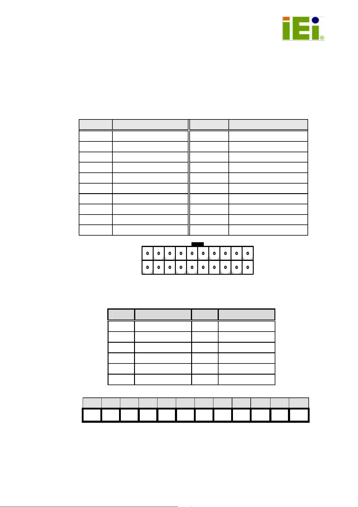
1. PW2: ATX Power Connector
Pin Description Pin Description
1
2
3
4
5
6
7
8
9
10
+3.3Vdc
+3.3Vdc
GND
+5Vdc
GND
+5Vdc
GND
PWR-OK
+5VSB
+12Vdc
11
12
13
14
15
16
17
18
19
20
+3.3Vdc
-12Vdc
GND
PS-ON
GND
GND
GND
-5Vdc
+5Vdc
+5Vdc
20
2. PW1: AT Power Connector
1 2 3 4 5 6 7 8 9 10 11 12
▓ ▓ ▓ ▓ ▓ ▓ ▓ ▓ ▓ ▓ ▓ ▓
Pin Description Pin Description
1 PWRGD 7 GND
2 +5V 8 GND
3 +12V 9 -5V
4 -12V 10 +5V
5 GND 11 +5V
6 GND 12 +5V
11
110
1
Page 2
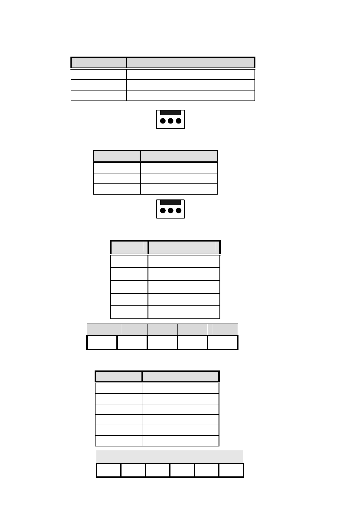
3. CN2: Backplane to Mainboard ATX power control Connector
Pin Description
1 5VSB
2 PSON#
3 GND
123
4. CN3, CN5: Fan Connector
Pin Description
1 NC
2 +12V
3 GND
5. CN1: Voltage Connector
Pin Description
1 +5V
2 -5V
3 -12V
1 2 3 4 5
▓ ▓ ▓ ▓ ▓
4 +12V
5 GND
6. PW4, PW5: Power Connector
Pin Description
1 +5V
2 +5V
123
3 +5V
4 GND
5 GND
6 GND
1 2 3 4 5 6
▓
●
● ● ● ●
2
Page 3
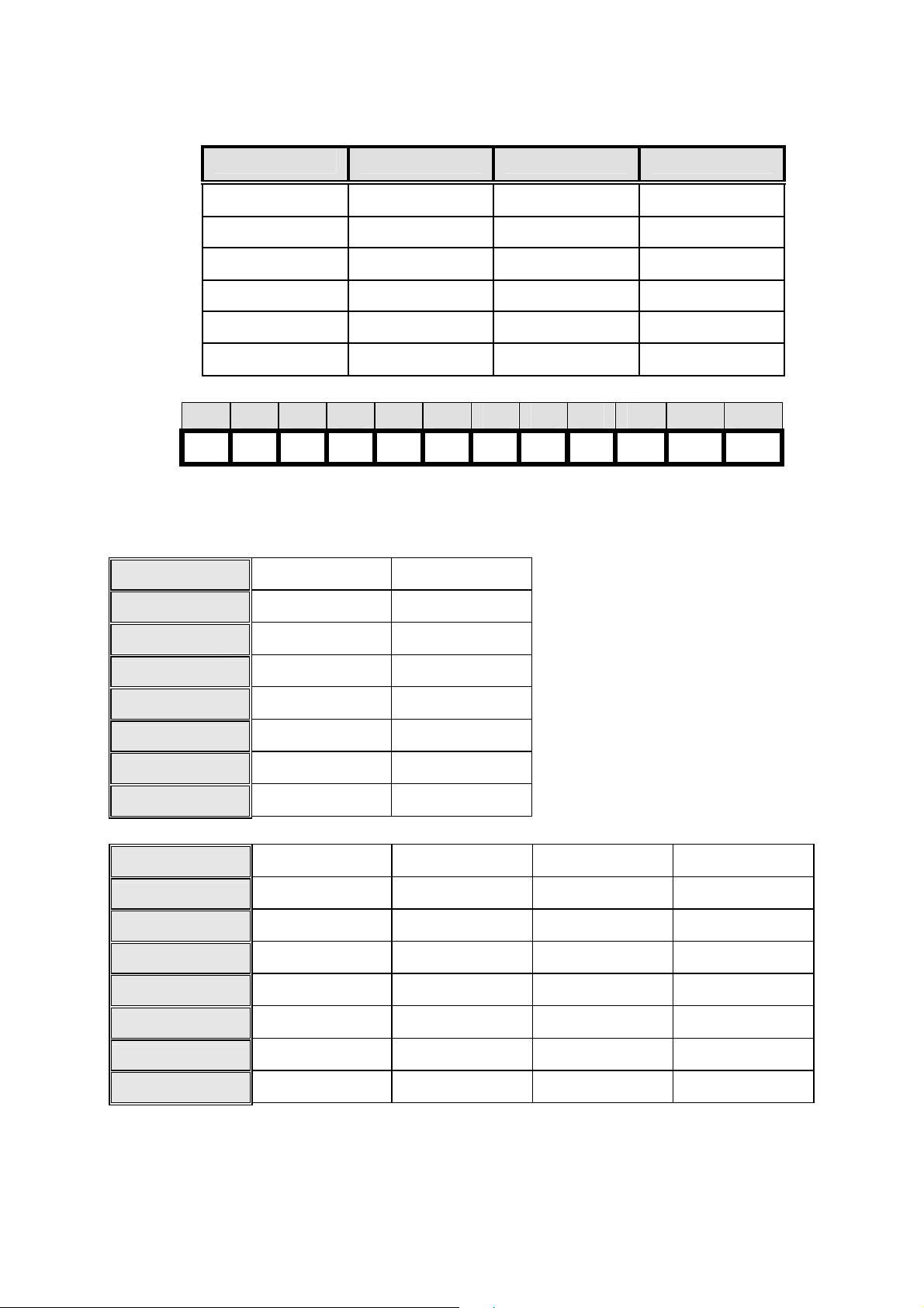
7. PW3: Power Connector
8. PCI routing table:
1 2 3 4 5 6 7 8 9 10 11 12
▓ ▓ ▓ ▓ ▓ ▓ ▓ ▓ ▓ ▓ ▓
Pin Description Pin Description
1 PWR_GD 7 GND
2 +5V 8 GND
3 +12V 9 -5V
4 -12V 10
5 GND 11
6 GND 12
+5V
+5V
+5V
▓
PCI SLOT PCI3 PCI4
IDSEL
REQ# REQ0# REQ3#
GNT#
INTA B A
INTB
INTC D C
INTD
PCI SLOT
IDSEL 2_AD20 2_AD21 2_AD22 2_AD23
REQ#
GNT# 2_GNT0# 2_GNT1# 2_GNT2# 2_GNT3
INTA
INTB
AD31 AD28
GNT0# GNT3#
C
A
C
PCI5
2_REQ0#
B
D
D
PCI6
2_REQ1#
A
PCI7
2_REQ2#
2_REQ3
D A B C
PCI8
B
INTC A B C D
INTD
B C D A
3
Page 4

PCI SLOT
IDSEL 2_AD24 2_AD25 2_AD26 2_AD27
REQ# 2_REQ4# 2_REQ5# 2_REQ6# 2_REQ7
PCI9
PCI 10
PCI 11
PCI 12
GNT#
INTA C D A B
INTB
INTC A B C D
INTD
PCI SLOT PCI 13 PCI 14 PCI 15 PCI 16
IDSEL
REQ# 3_REQ0# 3_REQ1# 3_REQ2# 3_REQ3
GNT#
INTA D A B C
INTB
INTC
INTD C D A B
2_GNT4# 2_GNT5# 2_GNT6# 2_GNT7
D A B C
B C D A
3_AD20
3_GNT0#
A
3_AD21
3_GNT1#
B
3_AD22
3_GNT2#
C
3_AD23
3_GNT3
D
B C D A
PCI SLOT PCI 17 PCI 18 PCI 19 PCI 20
IDSEL
REQ# 3_REQ4# 3_REQ5# 3_REQ6# 3_REQ7
GNT#
INTA D A B C
INTB
INTC B C D A
INTD
9. Notice:
a. Recommend to use 6mm width spacer to install
3_AD24 3_AD25 3_AD26 3_AD27
3_GNT4# 3_GNT5# 3_GNT6# 3_GNT7
A
C
B
D
C
A
D
B
b. Torsion must less than 6lb-i nch
4
Page 5
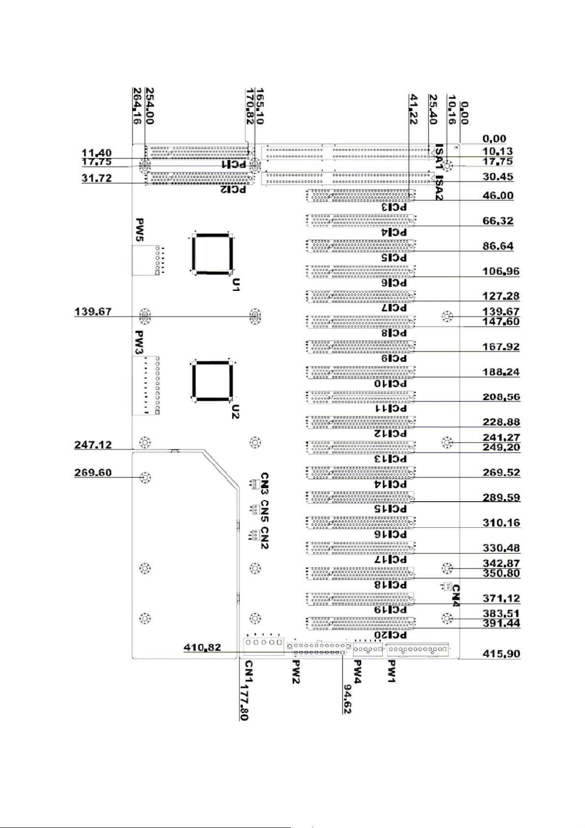
10. Dimension:
5
 Loading...