

Page 1

PX-10S
ISA/PCI Bridge Backplane
User’s Manual
ICP Electronics Inc.
@Copyright 2000
All Rights Reserved.
Manual first edition January 2000
The information in this document is subject to change without prior notice in order to
improve reliability, design and function and does not represent a commitment on the
part of the manufacture.
Page 2

C
o
n
t
e
n
t
s
C
o
n
t
e
n
t
s
C
o
n
t
e
n
t
s
Introduction ……………………………………………………………………………2
Product Features …………………...……………………………………………………2
Routing List ……………………………………...………………………………….…3
Board Drawing ………………………………...………………………………………..3
Connectors ………………………………...………………………………………4
Pin Assignment ………………………………………………………………………….4
Installation Guide ………………………...……………………………………………..4
1
PX-10S User’s Manual
Page 3

PX-10S ISA/PCI Bridge Backplane
Introduction
PX-10S is exactly the backplane what you want, even in the future. As you know, most of the
adapters are of PCI bus, and ISA adapters are on the decrease in the market. If this problem have
bothered you for a long time, then PX-10S is the right answer for you. In order to solve the problem,
PX-10S, includes 7 32-bit PCI slots (5V/3.3V) on board, gives the great flexibility for your
system’s extension. We have DC power outlet (including +5V, -5V, +12V, and -12V) on PX-10S to
keep system more stable. You can acquire a power supply with great stability, even as the system
work under heavy load. Besides, we also add a connector for ATX power supply to which you can
connect your SBC (SBC must have the ability to use ATX power).
Product Features
Standard
♦ PCI-conforms to PICMG 2.1 specification.
♦ ISA-conforms to IEEE P996 specification.
PCB
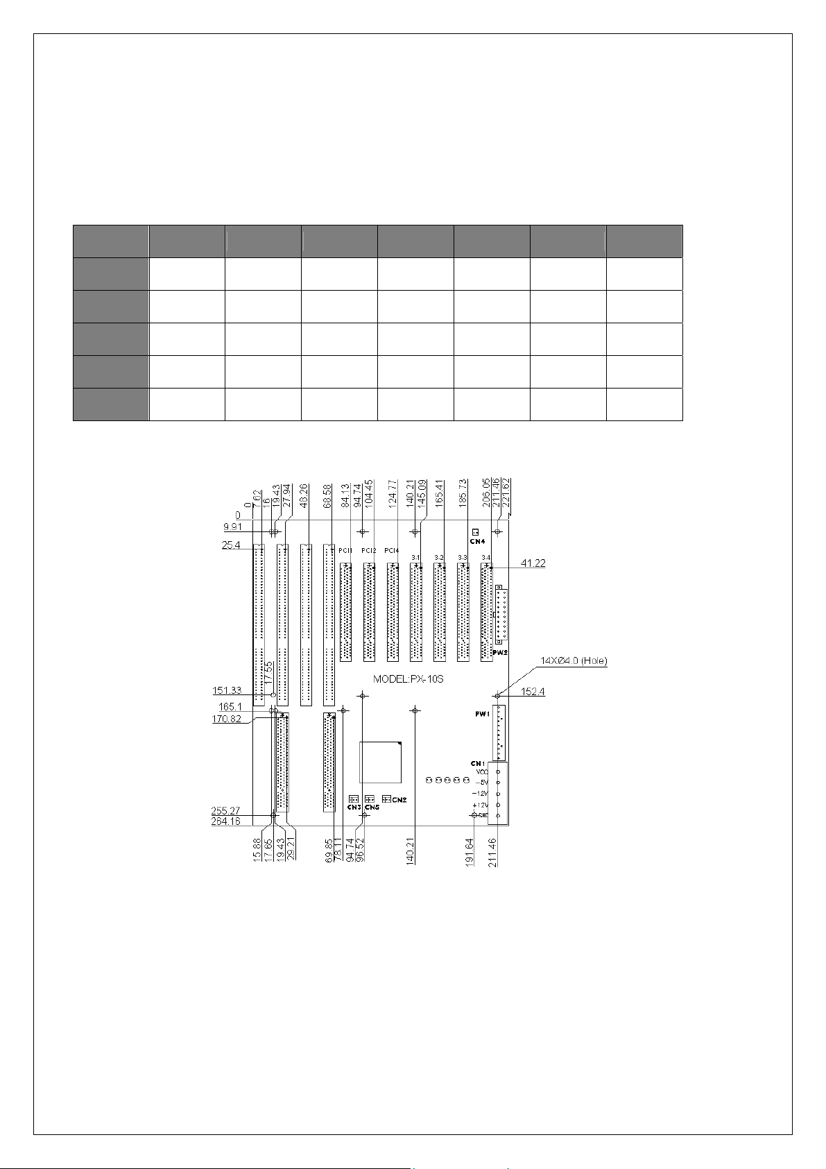
♦ The Printed Circuit Boards (PCB) overall dimension is 264.2mm x 221.6mm (10.4”x 8.8”) and
total thickness is 1.6mm (4 layers).
♦ Mounting holes are provided and are located to conform to the baby AT form factor. Mounting
holes are connected to Signal ground internally.
♦ Operating Temperature; 0 to 60°C (32 to 140°F).
♦ Storage Temperature; -20 to 85°C (-4 to 185°F).
♦ Humidity; 5% to 95%, non-condensing.
♦ EMI/Safety; Meets FCC, CE Class A and UL, CSA and TUV.
Connector
♦ Dual slots PCI/ISA for the CPU board.
♦ Two ISA slots for full-size ISA board.
♦ Seven 32-bit PCI slots for full-sized boards on the Primary bus, All slots are Master/Slave
configurable by using Bus Mastering Scheme.
♦ One AT standard power connector, 12 pins, 5A max, per pin for +5V,-5V, +12V, -12V voltages
and Ground.
♦ One ATX standard power connector; 20 pins, 5A max. per pin for +3.3V, +5V, +5VSB, -5V,
+12V, -12V voltages, Ground, and power Good signal.
♦ One ATX control connector to distribute signals coming from the CPU boards onto connector
2
PX-10S User’s Manual
Page 4
for soft on/off ATX power supply.
♦ One DC power outlet
♦ Pairs of header for local connection of a fan power, and power LEDs
Routing List
PCI SLOT
IDSEL AD31 AD30 AD28 S_AD23 S_AD22 S_AD21 S_AD20
INTA B C A D C B A
INTB C D B A D C B
INTC D A C B A D C
INTD A B D C B A D
1 2 4 3-1 3-2 3-3 3-4
Board Drawing
3
PX-10S User’s Manual
Page 5

Connectors
CONNECTOR DESCRIPTION
ISA2/PCI1 & ISA4/PCI2 PICMG connectors
PCI3-PCI9 32-BIT PCI BUS connectors
ISA1,ISA3 16-BIT ISA BUS connectors
PW1 P8/P9 power connector
PW2 ATX power connector
CN1 DC power outlet
CN2 ATX P/S control connector
CN3,CN5 Fan connector
CN4 Power good signal output
Pin Assignment
P8/P9(PW1)
PIN NAME
1 PWR OK
2 +5V
3 +12V
4 -12V
5 GND
6 GND
7 GND
8 GND
9 -5V
10 +5V
11 +5V
12 +5V
Power Good output(CN4)
PIN NAME
1 Power Good
2 GND
PIN NAME PIN NAME
1 +3.3V 11 +3.3V
2 +3.3V 12 -12V
3 GND 13 GND
4 +5V 14 PS_ON
5 GND 15 GND
6 +5V 16 GND
7 GND 17 GND
8
9 STB5V 19 +5V
10 +12V 20 +5V
ATX(PW2)
PWR
OK
18 -5V
Fan connector(CN3,CN5)
PIN NAME
1 NC
2 +12V
3 GND
Power Extension(CN1)
PIN NAME
1 +5V
2 -5V
3 -12V
4 +12V
5 GND
ATX control connector(CN2)
PIN NAME
1 STB5V
2 PS_ON
3 GND
Installation Guide
Chassis
Make sure the copper lifting stands are placed below all the mounting holes of your backplane.
SBC
Apply only one full-sized SBC over PICMG slot or half-sized SBC over ISA slot.
Apply your ISA/PCI cards over ISA/PCI slot (Image 1).
Power Supply
1.If you use AT power supply, attach the P8/P9 connector to PW1 (Image. 2).
2.If you use ATX power supply, attach the 20-pin ATX power connector to PW2 (Image. 3).
Besides, you need to apply one 3-pin ATX power control cable between your SBC and backplane
4
PX-10S User’s Manual
Page 6
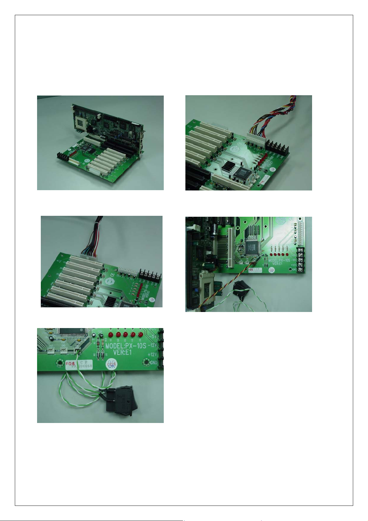
over the 3-pin header CN2. (A toggle switch is required over your SBC for this application.
Image. 4).
3.If you use ATX power supply, you may also plug a switch into pin-2 and pin-3 of CN2. In this
application, the 3-pin ATX power control cable is not required, and your ATX power supply will
then act as AT power supply (Image. 5).
Image 1
Image 3
Image 2
Image 4
Image 5
Fan
CN33 and CN5 are fan connectors. Please refer to the pin assignment table for proper connection.
5
PX-10S User’s Manual
 Loading...