

Page 1
IEI Technology Corp.
User Manual
PPC-51xxA-G41
®
PPC-51xxA-G41/WIDS-51xA-G41 Panel PC
MODEL:
WIDS-51xA-G41
Industrial Panel PC for LGA775 Intel
TFT LCD, Dual Gigabit Ethernet, Touchscreen,
IP 65 Front Panel, RoHS Compliant
Qaud Core CPU
Rev. 1.00 – 25 November, 2010
Page i
Page 2

Date Version Changes
25 November, 2010 1.00 Initial release
PPC-51xxA-G41/WIDS-51xA-G41 Panel PC
Revision
Page ii
Page 3

PPC-51xxA-G41/WIDS-51xA-G41 Panel PC
COPYRIGHT NOTICE
The information in this document is subject to change without prior notice in order to
improve reliability, design and function and does not represent a commitment on the part
of the manufacturer.
In no event will the manufacturer be liable for direct, indirect, special, incidental, or
consequential damages arising out of the use or inability to use the product or
documentation, even if advised of the possibility of such damages.
This document contains proprietary information protected by copyright. All rights are
Copyright
reserved. No part of this manual may be reproduced by any mechanical, electronic, or
other means in any form without prior written permission of the manufacturer.
TRADEMARKS
All registered trademarks and product names mentioned herein are used for identification
purposes only and may be trademarks and/or registered trademarks of their respective
owners.
Page iii
Page 4

PPC-51xxA-G41/WIDS-51xA-G41 Panel PC
Table of Contents
1 INTRODUCTION.......................................................................................................... 1
1.1 GENERAL OVERVIEW ................................................................................................. 2
1.1.1 Model Variations................................................................................................ 2
1.1.2 Applications ....................................................................................................... 3
1.1.3 Features ............................................................................................................. 4
1.2 EXTERNAL OVERVIEW................................................................................................ 4
1.2.1 Front Panel........................................................................................................ 5
1.2.2 Rear Panel ......................................................................................................... 6
1.2.3 Top Panel ........................................................................................................... 6
1.2.4 Bottom Panel...................................................................................................... 7
1.2.5 Left Panel........................................................................................................... 8
1.2.6 Right Panel......................................................................................................... 8
1.3 INTERNAL OVERVIEW................................................................................................. 9
2 SPECIFICATIONS...................................................................................................... 10
2.1 INTRODUCTION..........................................................................................................11
2.1.1 System Specifications........................................................................................11
2.1.1.1 PPC-51xxA-G41 Specifications ................................................................11
2.1.1.2 WIDS-51xA-G41Specifications ............................................................... 14
2.2 DIMENSIONS............................................................................................................. 16
2.2.1 PPC-5150A-G41 Dimensions.......................................................................... 17
2.2.2 PPC-5170A-G41 Dimensions.......................................................................... 18
2.2.3 PPC-5190A-G41 Dimensions.......................................................................... 19
2.2.4 WIDS-515A-G41 Dimensions .......................................................................... 20
2.2.5 WIDS-517A-G41 Dimensions .......................................................................... 21
2.3 GRAPHICS SUPPORT.................................................................................................. 22
2.4 MEMORY.................................................................................................................. 22
2.5 STORAGE.................................................................................................................. 23
2.5.1 CompactFlash®................................................................................................ 23
2.5.2 Hard Drive....................................................................................................... 23
2.6 FRONT PANEL........................................................................................................... 24
Page iv
Page 5

PPC-51xxA-G41/WIDS-51xA-G41 Panel PC
2.6.1 Flat Screen....................................................................................................... 24
2.6.2 Touch Screen.................................................................................................... 24
2.7 POWER SUPPLY ........................................................................................................ 25
2.7.1.1 ACE-A622A-RS Specifications................................................................ 25
2.7.1.2 ACE-4520C-RS Specifications................................................................. 25
2.8 EXPANSION SLOTS.................................................................................................... 26
2.9 WIRELESS LAN (WIDS SERIES ONLY).................................................................... 26
3 UNPACKING............................................................................................................... 28
3.1 ANTI-STATIC PRECAUTIONS...................................................................................... 29
3.2 UNPACKING PRECAUTIONS....................................................................................... 29
3.3 PACKAGE CONTENTS................................................................................................ 30
4 INSTALLATION AND CONFIGURATION ............................................................ 32
4.1 INSTALLATION PRECAUTIONS ................................................................................... 33
4.2 PREINSTALLED COMPONENTS................................................................................... 33
4.3 INST ALLATION AND CONFIGURATION STEPS............................................................. 34
4.4 REMOVE THE BACK COVER...................................................................................... 35
4.5 JUMPER SETTINGS .................................................................................................... 36
4.5.1 Access the Jumpers.......................................................................................... 36
4.5.2 Preconfigured Jumpers.................................................................................... 37
4.5.3 CF Card Setup ................................................................................................. 37
4.5.4 COM1 to COM5 Pin 9 Select........................................................................... 38
4.5.5 COM5 RS-232/422/485 Serial Port Select Jumper ......................................... 39
4.5.5.1 COM 5 RS-422 and RS-485 Pinouts........................................................ 40
4.6 DRIVE INSTALLATION............................................................................................... 41
4.6.1 Hard Drive Installation.................................................................................... 41
4.6.2 CompactFlash® Installation............................................................................. 43
4.6.3 CD Drive Installation ...................................................................................... 44
4.7 PCI EXPANSION CARD INSTALLATION (OPTIONAL).................................................. 49
4.8 PCIE EXPANSION CARD INSTALLATION (OPTIONAL)................................................ 51
4.9 AT/ATX MODE SELECTION...................................................................................... 53
4.10 ACTIVATING THE FRONT USB CONNECTORS (WIDS SERIES ONLY)....................... 53
4.11 MOUNTING THE SYSTEM ........................................................................................ 55
4.1 1.1 Wall Mounting................................................................................................ 55
Page v
Page 6

4.11.2 Panel/ Mounting............................................................................................. 58
4.11.3 Rack and Cabinet Installation........................................................................ 63
4.1 1.4 Arm Mounting ................................................................................................ 63
5 BIOS SETUP................................................................................................................ 65
5.1 INTRODUCTION......................................................................................................... 67
5.1.1 Starting Setup................................................................................................... 67
5.1.2 Using Setup...................................................................................................... 67
5.1.3 Getting Help..................................................................................................... 68
5.1.4 Unable to Reboot after Configuration Changes.............................................. 68
5.1.5 BIOS Menu Bar................................................................................................ 68
5.2 MAIN........................................................................................................................ 69
5.3 ADVANCED............................................................................................................... 70
5.3.1 CPU Configuration.......................................................................................... 71
5.3.2 IDE Configuration........................................................................................... 72
PPC-51xxA-G41/WIDS-51xA-G41 Panel PC
5.3.2.1 IDE Master, IDE Slave............................................................................. 74
5.3.3 Super IO Configuration ................................................................................... 77
5.3.4 Hardware Health Configuration...................................................................... 83
5.3.5 Power Configuration ....................................................................................... 86
5.3.5.1 ACPI Settings............................................................................................ 87
5.3.5.2 APM Configuration................................................................................... 87
5.3.6 Remote Access Configuration.......................................................................... 90
5.3.7 USB Configuration........................................................................................... 93
5.4 PCI/PNP................................................................................................................... 95
5.5 BOOT........................................................................................................................ 97
5.5.1 Boot Settings Configuration............................................................................. 98
5.6 SECURITY............................................................................................................... 100
5.7 CHIPSET ................................................................................................................. 101
5.7.1 North Bridge Configuration........................................................................... 102
5.7.1.1 V ideo Function Configuration ................................................................ 103
5.7.2 South Bridge Configuration........................................................................... 104
5.8 EXIT....................................................................................................................... 105
6 SYSTEM MAINTENANCE ..................................................................................... 107
6.1 SYSTEM MAINTENANCE INTRODUCTION ................................................................ 108
Page vi
Page 7

PPC-51xxA-G41/WIDS-51xA-G41 Panel PC
6.2 MOTHERBOARD REPLACEMENT ............................................................................. 108
6.3 BACK COVER REMOVAL......................................................................................... 108
6.4 DIMM REPLACEMENT........................................................................................... 109
6.5 ELEVATED PLATFORM REMOVAL .............................................................................110
6.6 PSU MODULE REPLACEMENT.................................................................................112
6.6.1 Remove the Old PSU.......................................................................................112
6.6.2 Install the New PSU........................................................................................114
6.7 SYSTEM COOLING FAN REPLACEMENT....................................................................115
6.7.1 Remove the Old System Cooling Fans............................................................115
6.7.2 Install the New System Cooling Fans .............................................................116
A BIOS OPTIONS .........................................................................................................117
B TERMINOLOGY...................................................................................................... 121
C DIGITAL I/O INTERFACE..................................................................................... 125
C.1 INTRODUCTION...................................................................................................... 126
C.2 DIO CONNECTOR PINOUTS.................................................................................... 126
C.3 ASSEMBLY LANGUAGE SAMPLES........................................................................... 127
C.3.1 Enable the DIO Input Function..................................................................... 127
C.3.2 Enable the DIO Output Function.................................................................. 127
D WATCHDOG TIMER .............................................................................................. 128
E ADDRESS MAPPING .............................................................................................. 131
E.1 DIRECT MEMORY ACCESS (DMA)......................................................................... 132
E.2 INPUT/OUTPUT (IO)............................................................................................... 133
E.3 INTERRUPT REQUEST (IRQ)................................................................................... 135
E.4 MEMORY................................................................................................................ 136
F HAZARDOUS MATERIALS DISCLOSURE........................................................ 137
F.1 HAZARDOUS MATERIALS DISCLOSURE TABLE FOR IPB PRODUCTS CERTIFIED AS
ROHS COMPLIANT UNDER 2002/95/EC WITHOUT MERCURY ..................................... 138
Page vii
Page 8

PPC-51xxA-G41/WIDS-51xA-G41 Panel PC
List of Figures
Figure 1-1: PPC-51xxA-G41 Panel PC ..........................................................................................2
Figure 1-2: PPC-51xxA-G41 Front View........................................................................................5
Figure 1-3: WIDS-51xA-G41 Front View........................................................................................5
Figure 1-4: Rear View.....................................................................................................................6
Figure 1-5: Top View.......................................................................................................................6
Figure 1-6: Bottom View ................................................................................................................7
Figure 1-7: Left View.......................................................................................................................8
Figure 1-8: Right View....................................................................................................................8
Figure 1-9: Internal Components..................................................................................................9
Figure 2-1: PPC-5150A-G41 Dimensions (units in mm)............................................................17
Figure 2-2: PPC-5170A-G41 Dimensions (units in mm)............................................................18
Figure 2-3: PPC-5190A-G41 Dimensions (units in mm)............................................................19
Figure 2-4: WIDS-515A-G41 Dimensions (units in mm)............................................................20
Figure 2-5: WIDS-517A-G41 Dimensions (units in mm)............................................................21
Figure 2-6: DIMM Sockets............................................................................................................22
Figure 2-7: CompactFlash® Slot.................................................................................................23
Figure 2-8: SATA Hard Drive Slot ...............................................................................................24
Figure 2-9: Expansion Card Slot.................................................................................................26
Figure 2-10: Wireless LAN Module (Installed by Users)...........................................................27
Figure 2-11: Antenna....................................................................................................................27
Figure 4-1: Back Cover Retention Screws.................................................................................35
Figure 4-2: CF Card Setup Jumper Location.............................................................................38
Figure 4-3: COM1 to COM5 Pin 9 Setting Jumper Locations...................................................39
Figure 4-4: COM5 RS-232/422/485 Serial Port Select Jumper Location..................................40
Figure 4-5: HDD Retention Screws.............................................................................................41
Figure 4-6: HDD SATA Connector...............................................................................................42
Figure 4-7: HDD Retention Screws.............................................................................................42
Figure 4-8: HDD Retention Screws.............................................................................................43
Figure 4-9: CompactFlash® Cover Plate....................................................................................43
Figure 4-10: CompactFlash® Slot...............................................................................................44
Page viii
Page 9

PPC-51xxA-G41/WIDS-51xA-G41 Panel PC
Figure 4-11: CompactFlash® Cover Plate..................................................................................44
Figure 4-12: CD Drive Adapter Installation ................................................................................45
Figure 4-13: CD Drive Retention Screws....................................................................................45
Figure 4-14: Optical Drive Blank Plate Assembly .....................................................................46
Figure 4-15: Optical Drive Screws ..............................................................................................47
Figure 4-16: Optical Drive SATA Cable ......................................................................................48
Figure 4-17: Optical Drive Bracket Screws................................................................................48
Figure 4-18: Secure the PCI Riser Card .....................................................................................49
Figure 4-19: Expansion Slot Retention Screw...........................................................................50
Figure 4-20: Install PCI Card........................................................................................................50
Figure 4-21: Secure the PCIe Riser Card ...................................................................................51
Figure 4-22: Expansion Slot Retention Screw...........................................................................52
Figure 4-23: Install PCIe Card......................................................................................................52
Figure 4-24: AT/ATX Power Switch Selection............................................................................53
Figure 4-25: Access the Front USB Connectors.......................................................................54
Figure 4-26: USB Switch..............................................................................................................54
Figure 4-27: Green LED................................................................................................................55
Figure 4-28: Wall-mounting Bracket...........................................................................................56
Figure 4-29: Mount the Chassis..................................................................................................57
Figure 4-30: Secure the Chassis.................................................................................................58
Figure 4-31: PPC-5150A-G41 Panel Cutout Dimensions..........................................................59
Figure 4-32: PPC-5170A-G41 Panel Cutout Dimensions..........................................................59
Figure 4-33: PPC-5190A-G41 Panel Cutout Dimensions..........................................................60
Figure 4-34: WIDS-515A-G41 Panel Cutout Dimensions..........................................................60
Figure 4-35: WIDS-517A-G41 Panel Cutout Dimensions..........................................................61
Figure 4-36: Panel Mounting Clamp Positions..........................................................................62
Figure 4-37: Tighten the Panel Mounting Clamp Screws.........................................................62
Figure 4-38: Arm Mount Retention Screw Holes.......................................................................64
Figure 6-1: DIMM Socket Clip Locations................................................................................. 110
Figure 6-2: Top Panel Elevated Platform Screws................................................................... 110
Figure 6-3: Side Panel Elevated Platform Screws.................................................................. 111
Figure 6-4: Bottom Panel Elevated Platform Screws............................................................. 111
Figure 6-5: Internal Elevated Platform Screws....................................................................... 112
Figure 6-6: PSU Power Cables................................................................................................. 113
Figure 6-7: PSU Bottom Panel Retention Screws.................................................................. 113
Page ix
Page 10

Figure 6-8: PSU Rear Panel Screws......................................................................................... 114
Figure 6-9: System Cooling Fans Motherboard Connector .................................................. 115
Figure 6-10: System Cooling Fans Left Panel Retention Screws......................................... 116
PPC-51xxA-G41/WIDS-51xA-G41 Panel PC
Page x
Page 11

PPC-51xxA-G41/WIDS-51xA-G41 Panel PC
List of Tables
Table 1-1: PPC-51xxA-G41 Model Variations...............................................................................3
Table 1-2: WIDS-51xA-G41 Model Variations...............................................................................3
Table 2-1: PPC-51xxA-G41 Series System Specifications.......................................................13
Table 2-2: WIDS-51xA-G41 Series System Specifications .......................................................16
Table 3-1: Package List Contents...............................................................................................31
Table 4-1: Jumpers.......................................................................................................................36
Table 4-2: Preconfigured Jumpers .............................................................................................37
Table 4-3: CF Card Setup Jumper Settings ...............................................................................37
Table 4-4: COM1 to COM5 Pin 9 Setting Jumper Settings .......................................................38
Table 4-5: COM5 RS-232/422/485 Serial Port Select Jumper Settings....................................39
Table 4-6: COM5 RS-422 Pinouts................................................................................................40
Table 4-7: COM5 RS-485 Pinouts................................................................................................40
Table 5-1: BIOS Navigation Keys................................................................................................68
Page xi
Page 12

PPC-51xxA-G41/WIDS-51xA-G41 Panel PC
BIOS Menus
BIOS Menu 1: Main.......................................................................................................................69
BIOS Menu 2: Advanced..............................................................................................................71
BIOS Menu 3: CPU Configuration...............................................................................................71
BIOS Menu 4: IDE Configuration.................................................................................................72
BIOS Menu 5: IDE Master and IDE Slave Configuration...........................................................74
BIOS Menu 6: Super IO Configuration........................................................................................78
BIOS Menu 7: Hardware Health Configuration..........................................................................83
BIOS Menu 8: Power Configuration............................................................................................86
BIOS Menu 9: ACPI Settings .......................................................................................................87
BIOS Menu 10: APM Configuration.............................................................................................88
BIOS Menu 11: Remote Access Configuration..........................................................................90
BIOS Menu 12: USB Configuration.............................................................................................93
BIOS Menu 13: PCI/PnP Configuration.......................................................................................95
BIOS Menu 14: Boot.....................................................................................................................97
BIOS Menu 15: Boot Settings Configuration.............................................................................98
BIOS Menu 16: Security............................................................................................................ 100
BIOS Menu 17: Chipset............................................................................................................. 101
BIOS Menu 18:North Bridge Chipset Configuration.............................................................. 102
BIOS Menu 19: South Bridge Chipset Configuration............................................................. 104
BIOS Menu 20: South Bridge Chipset Configuration............................................................. 104
BIOS Menu 21: Exit.................................................................................................................... 105
Page xii
Page 13
PPC-51xxA-G41/WIDS-51xA-G41 Panel PC
1 Introduction
Chapter
1
Page 1
Page 14
1.1 General Overview
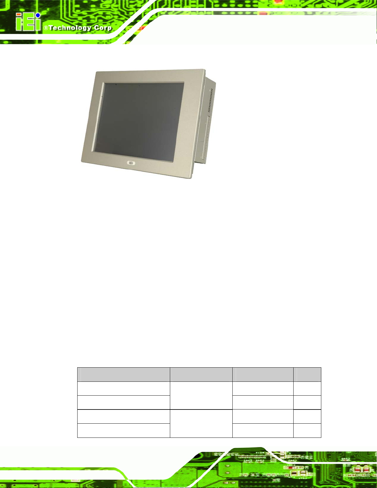
Figure 1-1: PPC-51xxA-G41 Panel PC
The PPC-51xxA-G41/WIDS-51xA-G41 flat panel PC is for industrial environments like
PPC-51xxA-G41/WIDS-51xA-G41 Panel PC
production lines and machine automation. The PPC-51xxA-G41/WIDS-51xA-G41
provides all the features of a PC, combined with a touch panel screen for mouse and
keyboard free data input. The PPC-51xxA-G41/WIDS-51xA-G41 provides wired
networking for integration into company networks and WIDS-51xA-G1 also provides
wireless network via PIFA antenna on the front panel. All major external device
connections including USB, serial and parallel port connectors. Storage options include a
2.5” hard drive and a CompactFlash® slot, allowing for flexibility in choosing solid state
drives or traditional hard drives. A VGA output on the rear panel allows the
PPC-51xxA-G41/WIDS-51xA-G41 to connect to a second screen for duplicating the
screen contents or extending the user interface.
1.1.1 Model Variations
Twelve IEI PPC-51xxA-G41 models are available. The models are listed in Table 1-1.
Model CPU Power Screen
PPC-5150A-G41-E15/R/1G AC input 15”
2.2 GHz Intel®
Page 2
PPC-5150AD-G41-E15/R/1G
PPC-5150A-G41-Q94/R/1G AC input 15”
PPC-5150AD-G41-Q94/R/1G
Celeron® E1500
2.66 GHz Intel®
Quad Core Q9400
18~36 V DC input 15”
18~36 V DC input 15”
Page 15
PPC-51xxA-G41/WIDS-51xA-G41 Panel PC
Model CPU Power Screen
PPC-5170A-G41-E15/R/1G AC input 17”
PPC-5170AD-G41-E15/R/1G
PPC-5170A-G41-Q94/R/1G AC input 17”
PPC-5170AD-G41-Q94/R/1G
PPC-5190A-G41-E15/R/1G AC input 19”
PPC-5190AD-G41-E15/R/1G
PPC-5190A-G41-Q94/R/1G AC input 19”
PPC-5190AD-G41-Q94/R/1G
Table 1-1: PPC-51xxA-G41 Model Variations
Eight IEI WIDS-51xA-G41 models are available. The models are listed in Table 1-1.
Model CPU Power Screen
WIDS-515A-G41-E15/R/1G AC input 15”
2.2 GHz Intel®
Celeron® E1500
2.66 GHz Intel®
Quad Core Q9400
2.2 GHz Intel®
Celeron® E1500
2.66 GHz Intel®
Quad Core Q9400
2.2 GHz Intel®
18~36 V DC input 17”
18~36 V DC input 17”
18~36 V DC input 19”
18~36 V DC input 19”
WIDS-515AD-G41-E15/R/1G
WIDS-515A-G41-Q94/R/1G AC input 15”
WIDS-515AD-G41-Q94/R/1G
WIDS-517A-G41-E15/R/1G AC input 17”
WIDS-517AD-G41-E15/R/1G
WIDS-517A-G41-Q94/R/1G AC input 17”
WIDS-517AD-G41-Q94/R/1G
Table 1-2: WIDS-51xA-G41 Model Variations
Celeron® E1500
2.66 GHz Intel®
Quad Core Q9400
2.2 GHz Intel®
Celeron® E1500
2.66 GHz Intel®
Quad Core Q9400
18~36 V DC input 15”
18~36 V DC input 15”
18~36 V DC input 17”
18~36 V DC input 17”
1.1.2 Applications
The PPC-51xxA-G41/WIDS-51xA-G41 flat panel PC is designed for rigorous industrial
environments where it may be exposed to both heat and moisture. Its durability and
strength also makes it an ideal choice for public access computers. Some possible
applications include:
Page 3
Page 16

1.1.3 Features
Some of the features of the PPC-51xxA-G41/WIDS-51xA-G41 flat panel PC include:
PPC-51xxA-G41/WIDS-51xA-G41 Panel PC
Automated manufacturing processes
Public information gathering point
Plant environment monitoring system
Factory automation
Manufacturing shop flow
Equipment and device control
Mainstream panel PC design with dual display function.
Aluminum die-casting front panel meet IP 65 water proof stand ard
Support LGA755 Intel® Core™2 Extreme/Quad/Duo, Celeron® processors
with 800/1066/1333 MHz FSB
Dual DDR3 memory DIMM (system max. 4 GB SDRAM)
SATA connectors
High brightness industrial grade LCD panel
The following I/O ports
o Five COM (one RS-232/422/485)
o One CompactFlash® slot
o One VGA port
o One Parallel port
o USB 2.0 ports
Dual 10/100/Gigabit Ethernet supported
RoHS compliant
1.2 External Overview
The PPC-51xxA-G41/WIDS-51xA-G41 flat panel PC is comprised of an LCD screen,
aluminum front panel and heavy duty steel rear and side panels. The rear panel provides
screw holes for wall and an arm mounting. The right panel provides access to a slim type
Page 4
CD drive bay. The bottom panel provides access to external interface connectors that
include GbE, USB 2.0, audio, parallel port, serial port connectors, VGA port and a
CompactFlash® card slot.
Page 17
PPC-51xxA-G41/WIDS-51xA-G41 Panel PC
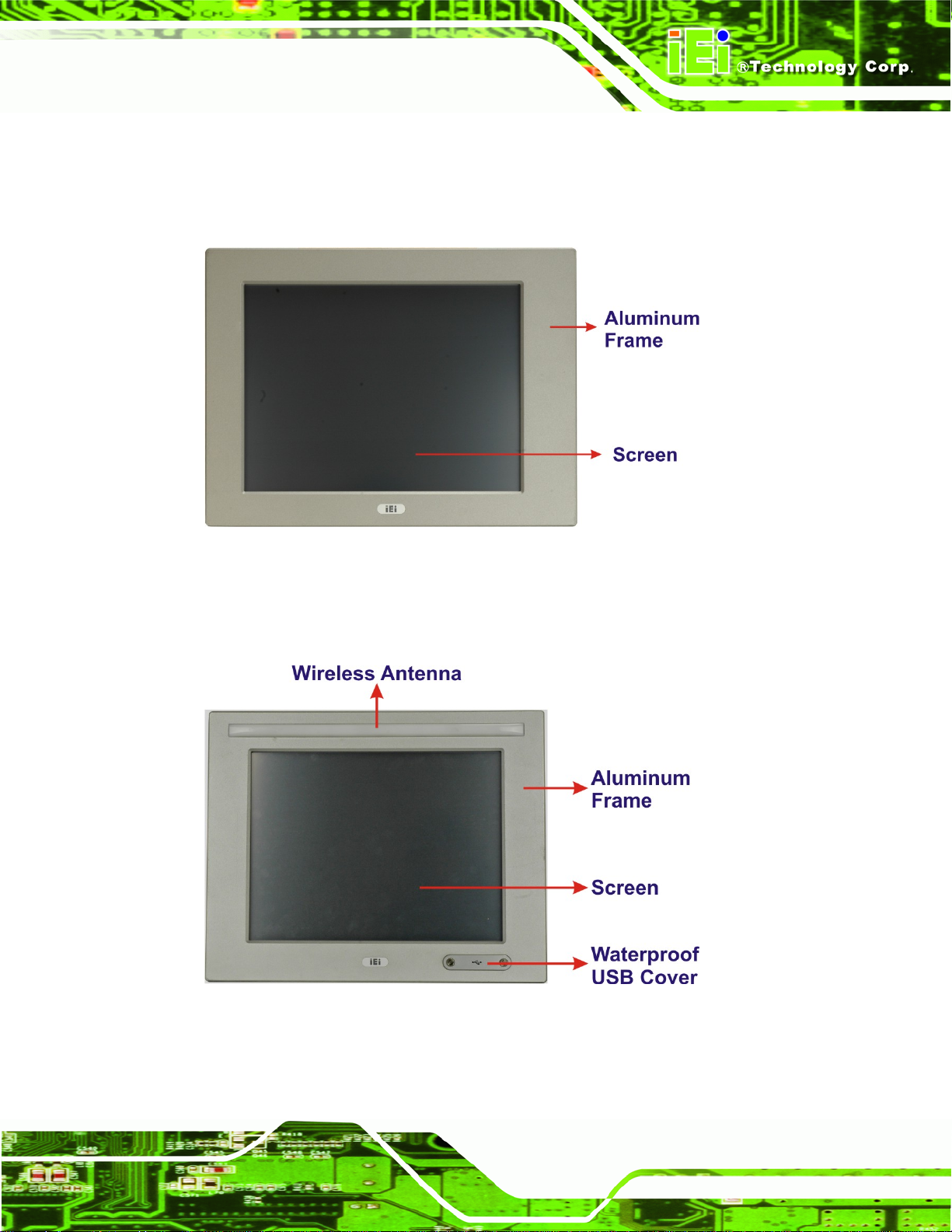
1.2.1 Front Panel
The front panel of the PPC-51xxA-G41/WIDS-51xA-G41 (Figure 1-2) is a flat panel TFT
LCD screen surrounded by an aluminum frame.
Figure 1-2: PPC-51xxA-G41 Front View
The WIDS-51xA-G41 also has wireless antenna and two USB ports protected by
waterproof cover on the front panel.
Figure 1-3: WIDS-51xA-G41 Front View
Page 5
Page 18
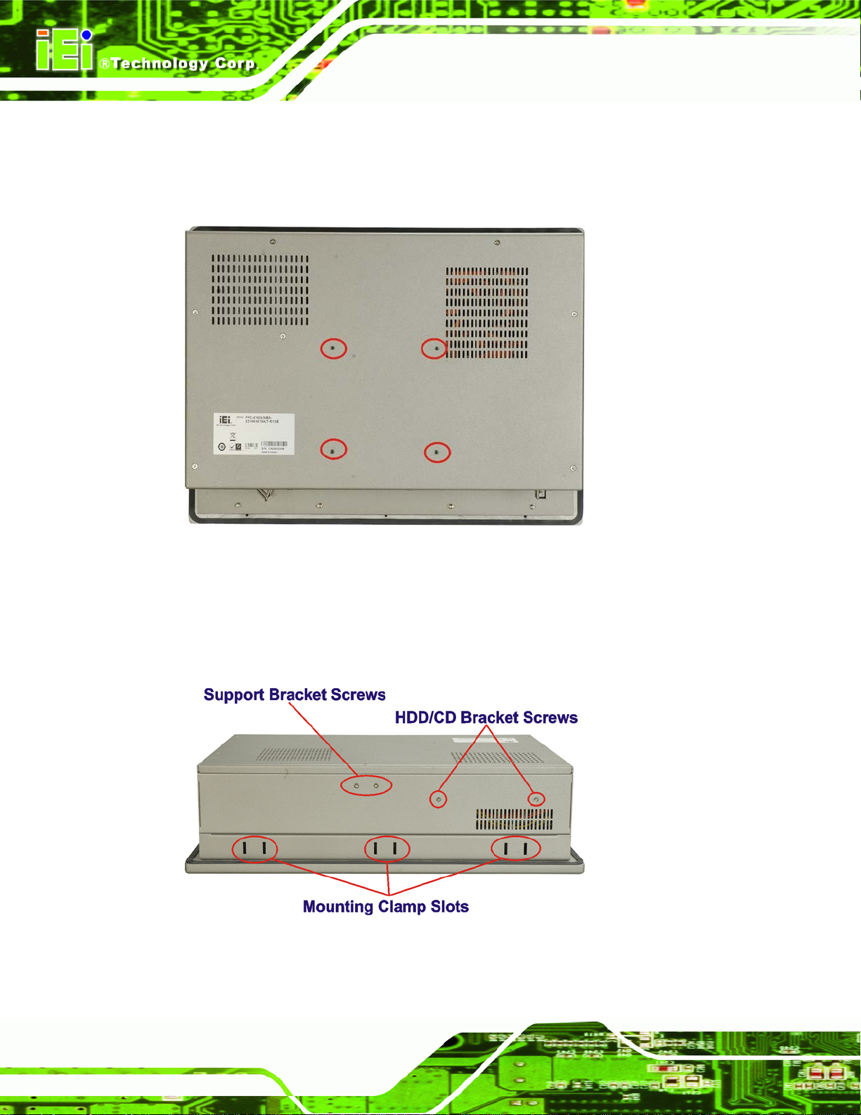
1.2.2 Rear Panel
The rear panel has a fan vent, four VESA standard mounting holes and several retention
PPC-51xxA-G41/WIDS-51xA-G41 Panel PC
screw holes. The VESA mounting holes are circled in
Figure 1-4: Rear View
1.2.3 Top Panel
Figure 1-4.
Page 6
The top panel has three sets of mounting clamp slot, fan vents and retention screws for
securing the drive bay bracket. The retention screws are circled in
Figure 1-5: Top View
Figure 1-5 below.
Page 19
PPC-51xxA-G41/WIDS-51xA-G41 Panel PC
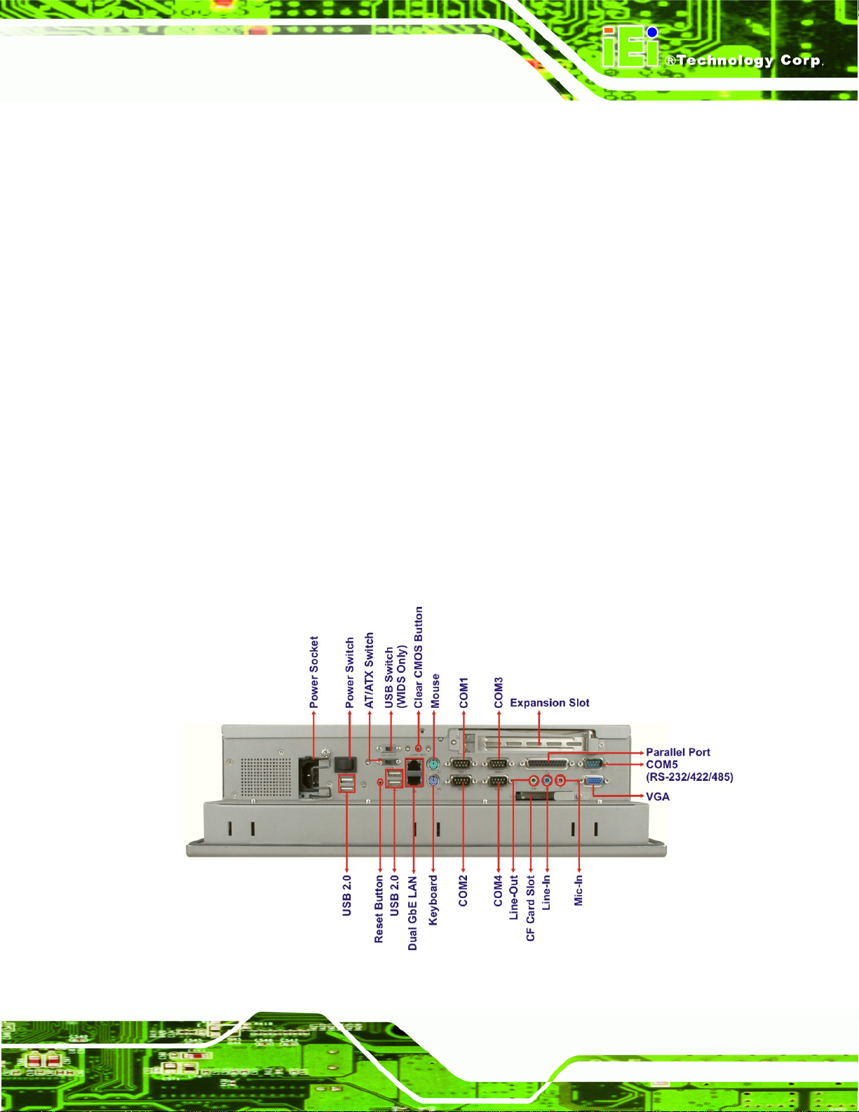
1.2.4 Bottom Panel
The bottom panel shown in Figure 1-6 has the following interfaces:
1 x Power input connector
1 x Power switch
4 x USB connectors (six USB ports for PPC-5190A-G41)
1 x Reset button
2 x RJ-45 GbE connectors
1 x PS/2 mouse connector
1 x PS/2 keyboard connector
4 x RS-232 connectors (COM1, COM2, COM3 and COM4)
1 x RS-232/422/485 connector (COM5)
1 x PCI/PCIe x1 add-on card slot
1 x Parallel port connector
3 x Audio jacks
1 x VGA connector
1 x CompactFlash® slot
1 x AT/ATX switch
1 x USB switch (WIDS series only)
Figure 1-6: Bottom View
Page 7
Page 20
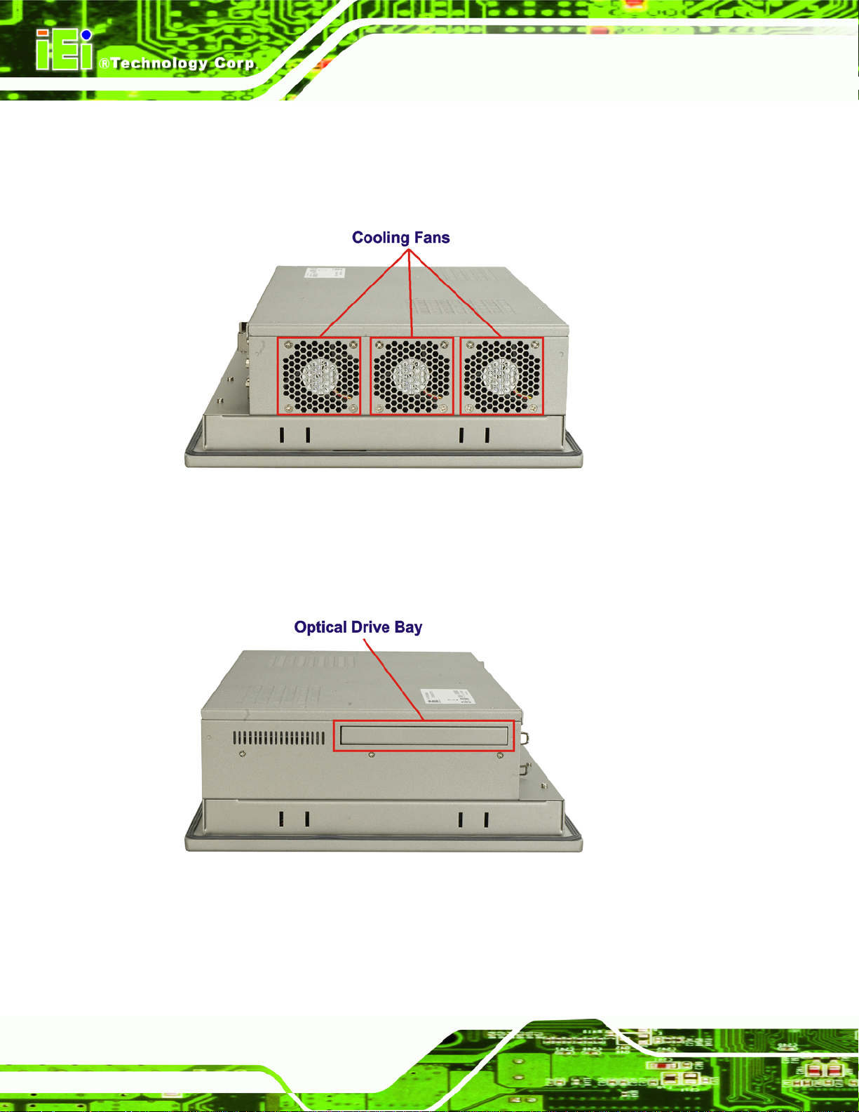
1.2.5 Left Panel
The left side panel hosts three cooling fans that cool the interior of the system
(
Figure 1-7).
PPC-51xxA-G41/WIDS-51xA-G41 Panel PC
Figure 1-7: Left View
1.2.6 Right Panel
The right panel has a CD-ROM drive bay for CD-ROM drive installation (Figure 1-8).
Figure 1-8: Right View
Page 8
Page 21
PPC-51xxA-G41/WIDS-51xA-G41 Panel PC
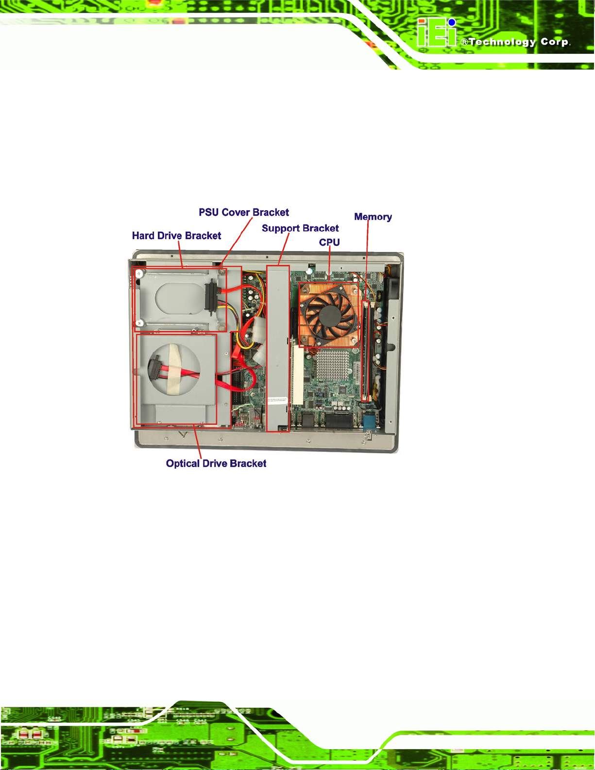
1.3 Internal Overview
The PPC-51xxA-G41/WIDS-51xA-G41 internal components are configure d in three levels.
The PSU cover bracket to the left (
brackets. Below the PSU cover bracket is the power supply. On the same level as the
power supply is the motherboard. Below the motherboard and PSU level is an LCD panel.
An overview picture of the internal components is shown in
Figure 1-9) supports the hard drive and optical drive
Figure 1-9 below.
Figure 1-9: Internal Components
Page 9
Page 22
PPC-51xxA-G41/WIDS-51xA-G41 Panel PC
Chapter
2
2 Specifications
Page 10
Page 23
PPC-51xxA-G41/WIDS-51xA-G41 Panel PC
2.1 Introduction
The PPC-51xxA-G41/WIDS-51xA-G41 flat panel PC has the following preinstalled
components:
1 x Motherboard
1 x TFT LCD screen
1 x Power supply
2 x Cooling fans
The technical specifications for these components and the system are shown in the
sections below.
2.1.1 System Specifications
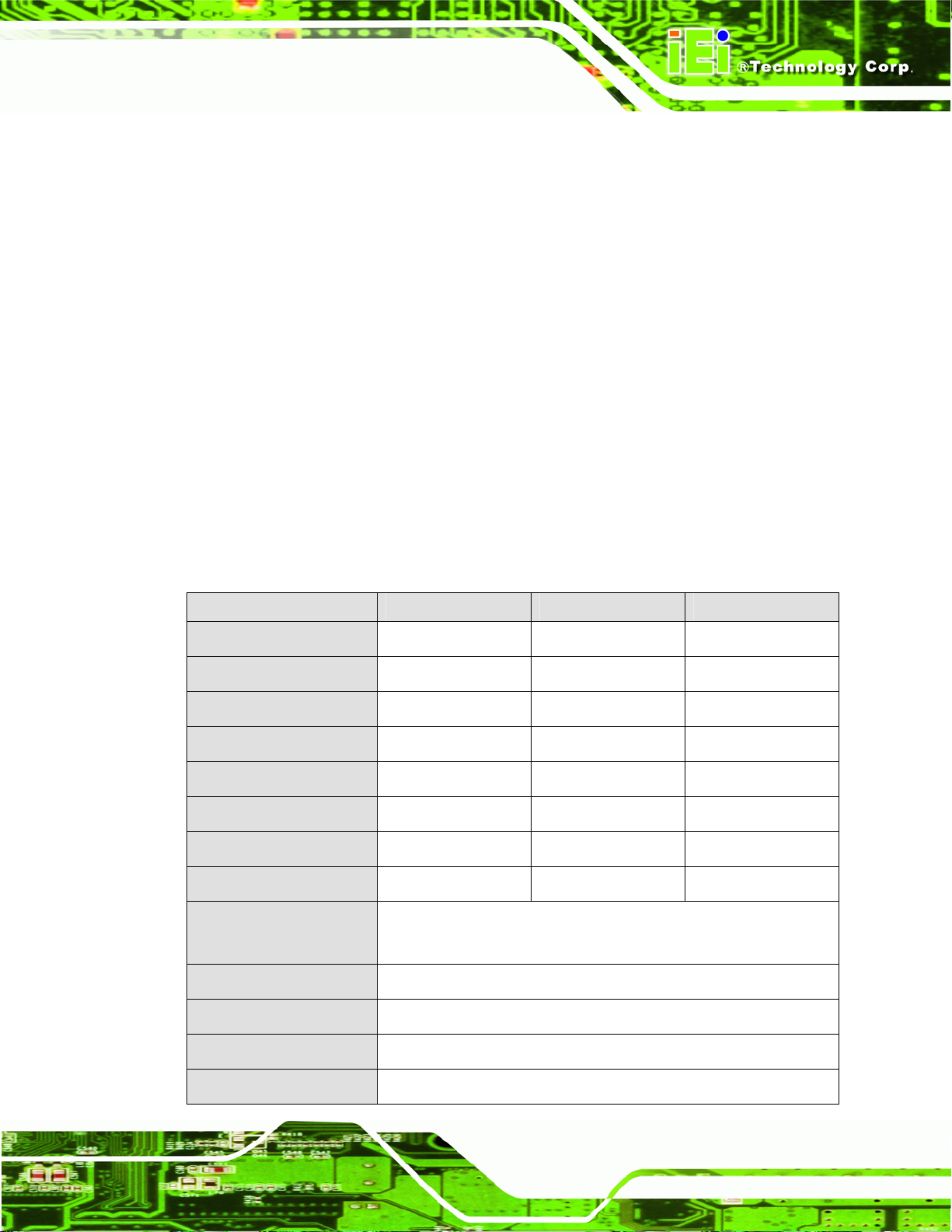
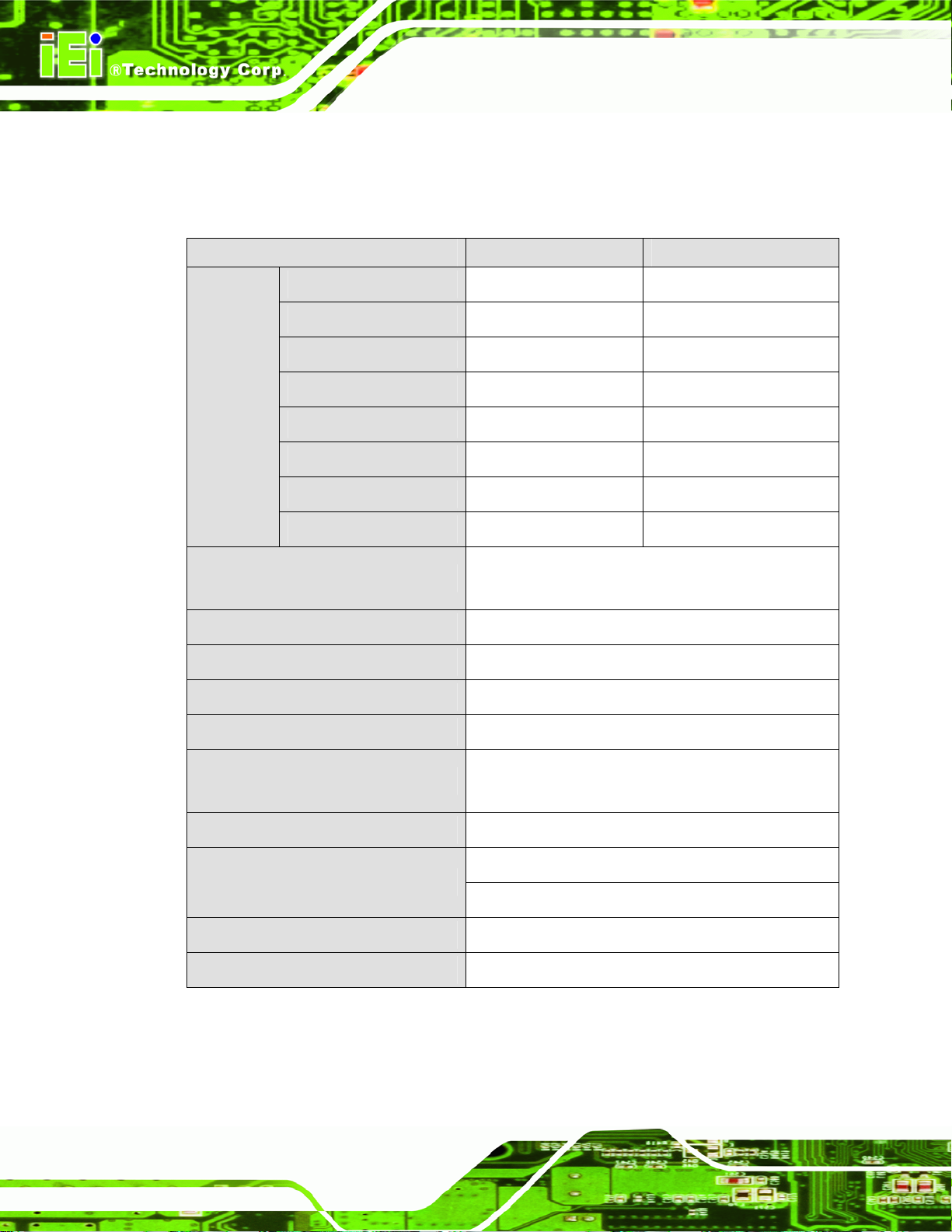
2.1.1.1 PPC-51xxA-G41 Specifications
The technical specifications for the PPC-51xxA-G41 system are listed below.
PPC-5150A-G41 PPC-5170A-G41 PPC-5190A-G41
Size
Resolution
Brightness
Contrast Ratio
Pixel Pitch (mm)
Viewing Angle (V-H)
LCD Color
Backlight MTBF
CPU
CPU Socket
15” 17” 19”
1024x768 (XGA) 1280x1024 (SXGA) 1280x1024 (SXGA)
350 cd/m
700:1 1000:1 1000:1
0.297 x 0.297 0.264 x 0.264 0.294 x 0.294
125/140 160/170 160/170
16.2M 16.7M 16.7M
50,000 hours 50,000 hours 50,000 hours
2.66GHz Intel® Core™2 Quad Q9400 or
2.20GHz Intel® Celeron® dual-core E1500
LGA775
2
380 cd/m2 450 cd/m2
Front Side Bus
Northbridge Chipset
Southbridge Chipset
800 MHz, 1066 MHz or 1333 MHz
Intel® G41
Intel® ICH7
Page 11
Page 24

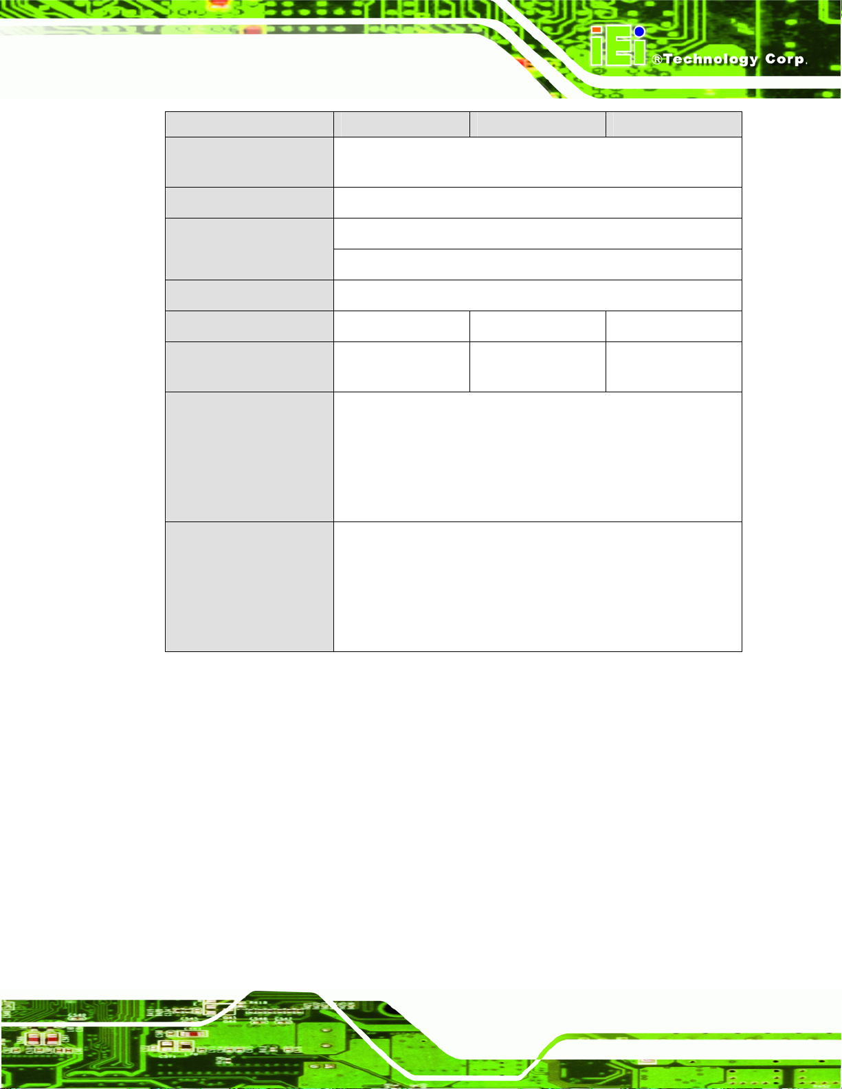
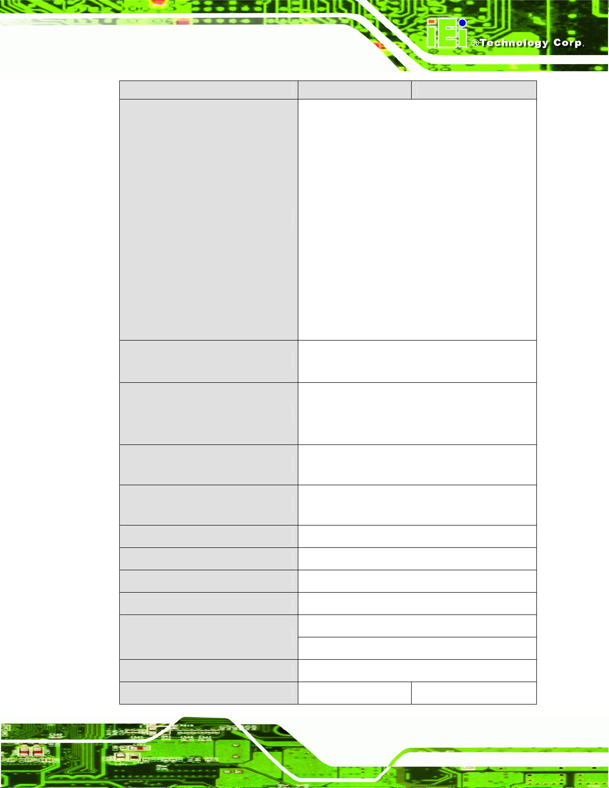
PPC-5150A-G41 PPC-5170A-G41 PPC-5190A-G41
PPC-51xxA-G41/WIDS-51xA-G41 Panel PC
Memory
Solid State Drive
(SSD)
Drive Bay
Ethernet
Audio
I/O ports
Two 2.0 GB 800/1066 MHz DDR3 SDRAM DIMM (system max.
4.0 GB)
One CompactFlash® Type II socket
One 2.5” SATA 3Gb/s or IDE anti-shock drive bay
One slim type CD-ROM bay
Two PCIe GbE controll ers
RealTek ALC888 HD audio codec
1 x RS-232/422/485
4 x RS-232
4 x USB 2.0 (six USB ports for PPC-5190A-G41 series)
2 x PS/2 for keyboard and mouse
1 x Parallel port connector
1 x VGA-out connector
2 x LAN connectors
Expansion Slots
Touch Screen
Mounting
Chassis Construction
Front Panel
Construction
3 x Audio connectors (line-in, line-out and mic-in)
1 x CMOS reset button
1 x AT/ATX switch
1 x Power switch
One PCIe Mini
Optional riser card:
One PCI slot or
One PCIe x4 with PCIe x1 signal
Resistive Type 5-wire (touch controller IC is on board)
VESA 100 mm x 100 mm
(panel, wall, rack, stand and arm)
Heavy-duty steel
Aluminum
Page 12
Page 25
PPC-51xxA-G41/WIDS-51xA-G41 Panel PC
PPC-5150A-G41 PPC-5170A-G41 PPC-5190A-G41
Operating
Temperature
Storage Temperature
Vibration
Shock
Net/Gross Weight
Dimensions (W x H x
D)
AC Input ATX
(A Model)
-10ºC ~ 50ºC
-20ºC ~ 60ºC
5 Hz ~ 17 Hz 0.1” double amplitude displacement
17 Hz ~ 640 Hz 1.5G acceleration peak-to-peak
10G acceleration peak-to-peak (11 ms)
7 kg/11 kg 8 kg/12 kg 12.6 kg/18.2 kg
410 x 309 x 110.5 452 x 356 x 115 483 x 399 x 115.2
ACE-A622A-RS
220 W
Input: 90 V AC~264 V AC, 50/60 Hz
Output(max.): 3.3 A@14 A, 5 V@16 A, 12 V@10 A, -12
V@0.8 A
ACE-4520C-RS
DC Input ATX
(AD Model)
Table 2-1: PPC-51xxA-G41 Series System Specifications
200 W
Input: 24 V DC (18~36 V DC), 50/60 Hz
-Output(max.): 3.3 A@12 A, 5 V@12 A, 12 V@15.4 A, -12
V@0.5 A
Page 13
Page 26
PPC-51xxA-G41/WIDS-51xA-G41 Panel PC
2.1.1.2 WIDS-51xA-G41 Specifications
The technical specifications for the WIDS-51xA-G41 system are listed below.
WIDS-515A-G41 WIDS-517A-G41
Size
Resolution
Brightness
LCD
Specs.
CPU
CPU Socket
Front Side Bus
Northbridge Chipset
Southbridge Chipset
Contrast Ratio
Pixel Pitch (mm)
Viewing Angle (V-H)
LCD Color
Backlight MTBF
15” 17”
1024 x 768 (XGA) 1280 x 1024 (SXGA)
350 cd/m
700:1 1000:1
0.297 x 0.297 0.264 x 0.264
125/140 160/170
16.2M 16.7M
50,000 hours 50,000 hours
2.66GHz Intel® Core™2 Quad Q9400 or
2.20GHz Intel® Celeron® dual-core E1500
LGA775
800 MHz, 1066 MHz or 1333 MHz
Intel® G41
Intel® ICH7
2
380 cd/m2
Page 14
Memory
Solid State Drive (SSD)
Drive Bay
Ethernet
Audio
Two 2.0 GB 800/1066 MHz DDR3 SDRAM DIMM
(system max. 4.0 GB)
One CompactFlash® Type II socket
One 2.5” SATA 3Gb/s or IDE anti-shock drive bay
One slim type CD-ROM bay
Two PCIe GbE controll ers
RealTek ALC888 HD audio codec
Page 27
PPC-51xxA-G41/WIDS-51xA-G41 Panel PC
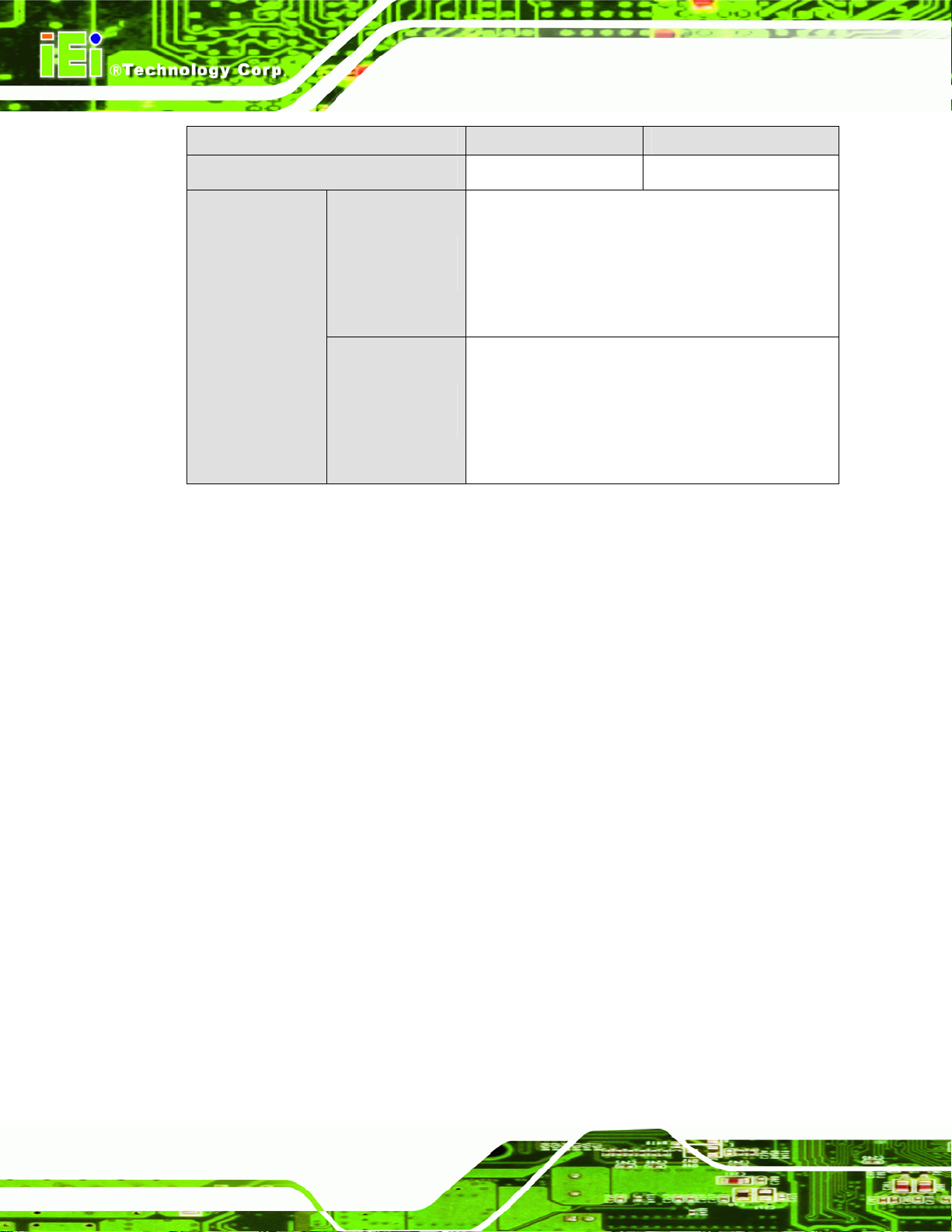
WIDS-515A-G41 WIDS-517A-G41
1 x RS-232/422/485
4 x RS-232
6 x USB 2.0 (two on front panel are waterproof)
2 x PS/2 for keyboard and mouse
1 x Parallel port connector
I/O ports
Wireless
Expansion Slots
Touch Screen
Mounting
1 x VGA-out connector
2 x LAN connectors
3 x Audio connectors (line-in, line-out and mic-in)
1 x CMOS reset button
1 x AT/ATX switch
1 x USB switch
1 x Power switch
802.11 b/g/n wireless PCIe Mini module
Wireless antenna embedded in front panel
Optional riser card:
One PCI slot or
One PCIe x4 with PCIe x1 signal
Resistive Type 5-wire (touch controller IC is on
board)
VESA 100 mm x 100 mm
(panel, wall, rack, stand and arm)
Chassis Construction
Front Panel Construction
Operating Temperature
Storage Temperature
Vibration
Shock
Net/Gross Weight
Heavy-duty steel
Aluminum
-10ºC ~ 50ºC
-20ºC ~ 60ºC
5 Hz ~ 17 Hz 0.1” double amplitude displacement
17 Hz ~ 640 Hz 1.5G acceleration peak-to-peak
10G acceleration peak-to-peak (11 ms)
7 kg/11 kg 8 kg/12 kg
Page 15
Page 28
WIDS-515A-G41 WIDS-517A-G41
PPC-51xxA-G41/WIDS-51xA-G41 Panel PC
Dimensions (W x H x D)
AC Input ATX
(A Model)
Power Supply
DC Input ATX
(AD Model)
Table 2-2: WIDS-51xA-G41 Series System Specifications
410 x 309 x 110.5 452 x 356 x 115
ACE-A622A-RS
220 W
Input: 90 V AC~264 V AC, 50/60 Hz
Output(max.): 3.3 A@14 A, 5 V@16 A,
12 V@10 A, -12 V@0.8 A
ACE-4520C-RS
200 W
Input: 24 V DC (18~36 V DC), 50/60 Hz
-Output(max.): 3.3 A@12 A, 5 V@12 A,
12 V@15.4 A, -12 V@0.5 A
2.2 Dimensions
The dimensions of the PPC-51xxA-G41/WIDS-51xA-G41 are shown in the sections
below.
Page 16
Page 29
PPC-51xxA-G41/WIDS-51xA-G41 Panel PC
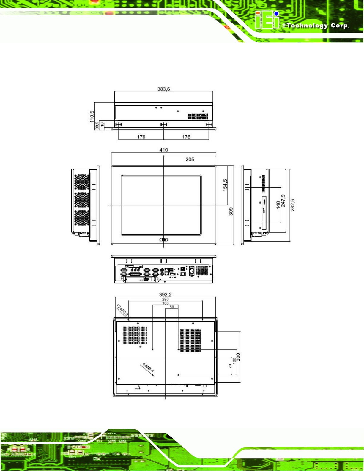
2.2.1 PPC-5150A-G41 Dimensions
The dimensions of the PPC-5150A-G41 flat panel PC are shown in Figure 2-1 below.
Figure 2-1: PPC-5150A-G41 Dimensions (units in mm)
Page 17
Page 30
2.2.2 PPC-5170A-G41 Dimensions
The dimensions of the PPC-5170A-G41 flat panel PC are shown in Figure 2-2 below.
PPC-51xxA-G41/WIDS-51xA-G41 Panel PC
Page 18
Figure 2-2: PPC-5170A-G41 Dimensions (units in mm)
Page 31

PPC-51xxA-G41/WIDS-51xA-G41 Panel PC
2.2.3 PPC-5190A-G41 Dimensions
The dimensions of the PPC-5190A-G41 flat panel PC are shown in Figure 2-3 below.
Figure 2-3: PPC-5190A-G41 Dimensions (units in mm)
Page 19
Page 32

2.2.4 WIDS-515A-G41 Dimensions
The dimensions of the WIDS-515A-G41 flat panel PC are shown below.
PPC-51xxA-G41/WIDS-51xA-G41 Panel PC
Page 20
Figure 2-4: WIDS-515A-G41 Dimensions (units in mm)
Page 33

PPC-51xxA-G41/WIDS-51xA-G41 Panel PC
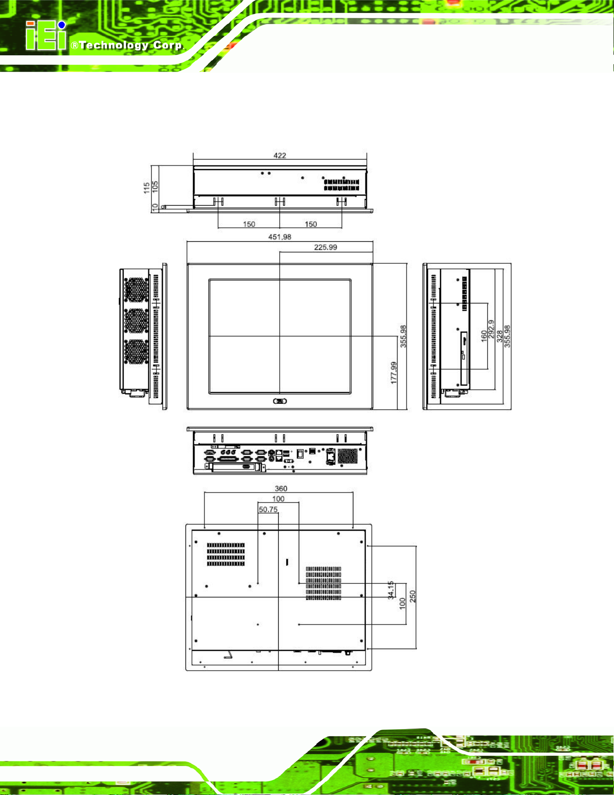
2.2.5 WIDS-517A-G41 Dimensions
The dimensions of the WIDS-517A-G41 flat panel PC are shown below.
Figure 2-5: WIDS-517A-G41 Dimensions (units in mm)
Page 21
Page 34

2.3 Graphics Support
The Intel® G41 chipset has an integrated graphics engine, Intel® Graphics Media
Accelerator X4500 that supports analog CRT display devices. The VGA port on the
external peripheral interface connector panel connects a peripheral monitor to the
PPC-51xxA-G41/WIDS-51xA-G41 system.
2.4 Memory
All processors supported by the PPC-51xxA-G41/WIDS-51xA-G41 have their own internal
DDR3 memory controller. The DDR3 controller has the following features:
Low-latency, high-bandwidth
Supports two 800 MHz, 1066 MHz or 1333 MHz DDR3 DIMMs
Each DIMM has a maximum capacity of 2.0 GB
PPC-51xxA-G41/WIDS-51xA-G41 Panel PC
The DDR3 controller on the processor is interfaced to two DIMM sockets on the
PPC-51xxA-G41/WIDS-51xA-G41.
Page 22
Figure 2-6: DIMM Sockets
Page 35

PPC-51xxA-G41/WIDS-51xA-G41 Panel PC
2.5 Storage
There following storage options are available:
CompactFlash®
SATA hard drive
2.5.1 CompactFlash®
The CompactFlash® socket supports standard Compa ctFlash® Type II cards. The chip set
flash interface is multiplexed with an IDE interface and can be connected to an array of
industry standard NAND Flash or NOR Flash devices. The CompactFlash® slot location is
shown below.
Figure 2-7: CompactFlash® Slot
2.5.2 Hard Drive
The PPC-51xxA-G41/WIDS-51xA-G41 comes has a single drive bay for 2.5” SATA 3Gb/s
hard drive or IDE hard drive.
Page 23
Page 36

Figure 2-8: SATA Hard Drive Slot
2.6 Front Panel
PPC-51xxA-G41/WIDS-51xA-G41 Panel PC
The front panel of the PPC-51xxA-G41/WIDS-51xA-G41 consists of an LCD monitor and a
touch screen panel.
2.6.1 Flat Screen
The PPC-51xxA-G41/WIDS-51xA-G41 comes with a TFT LCD monitor. The tough
construction of the TFT monitor allows the PPC-51xxA-G41/WIDS-51xA-G41 to withstand
the conditions it is likely to be exposed to during regular use. Some of the specifications of
the TFT monitors are shown below:
Pixel pitch of 0.297 mm or less
700:1 contrast ratio or better
350 cd/m
o
0
C to 50oC operating temperature
2
or greater
2.6.2 Touch Screen
The touch screen panel on the PPC-51xxA-G41/WIDS-51xA-G41 allows complete user
Page 24
interaction without the need for a keyboard or mouse. Some of the features of the touch
panel are listed below.
5-wire analog resistive type
Page 37

PPC-51xxA-G41/WIDS-51xA-G41 Panel PC
78% transmission
Control chipset built onto the motherboard
-10
7 V maximum voltage
o
C to 50oC operating temperature
2.7 Power Supply
The PPC-51xxA-G41/WIDS-51xA-G41 flat panel PC comes with either an ACE-A662A
220 W AC 1U, or ACE-4520C 200 W DC 1U RoHS compliant ATX power supply. The
PSUs have an MTBF greater than 100,000 hours.
WARNING:
Under no circumstances is the PSU case to be opened. The PSU
module is not user serviceable and there are dangerous high-voltages
inside the case. If there are any problems with the PSU module, please
contact the dealer or reseller immediately.
2.7.1.1 ACE-A622A-RS Specifications
Parameter
AC Input
Power Supply
Input
Output (max)
ACE-A618A-RS
A TX AC input
220W
90 VAC ~ 264 VAC @ 5 0 Hz/60 Hz
3.3 V 5 V 12 V -12 V
14 A 16 A 10 A 0.8 A
2.7.1.2 ACE-4520C-RS Specifications
Parameter
ACE-A618A-RS
Input
Power Supply
Input
ATX DC input
200 W
24 VDC @ 50 Hz/60 Hz
Page 25
Page 38

Output (max)
2.8 Expansion Slots
The riser card with either a PCI or PCIe x1 expansion card slot can be separately
purchased and installed in the PPC-51xxA-G41/WIDS-51xA-G41. The expansion card
slots add additional functionality to the PPC-51xxA-G41/WIDS-51xA-G41.
PPC-51xxA-G41/WIDS-51xA-G41 Panel PC
3.3 V 5 V 12 V -12 V
12 A 12 A 15.4 A 0.5 A
Figure 2-9: Expansion Card Slot
2.9 Wireless LAN (WIDS Series Only)
The WIDS-51xA series panel PC preinstalled an 802.11 b/g/n wireless LAN (WLAN)
module in the Mini-PCIe socket and interfaced to the Intel® ICH7 through the PCIe x1 bus.
Page 26
Page 39

PPC-51xxA-G41/WIDS-51xA-G41 Panel PC
Figure 2-10: Wireless LAN Module (Installed by Users)
The wireless module is then connected directly to the front panel PIFA antenna.
Figure 2-11: Antenna
Page 27
Page 40

PPC-51xxA-G41/WIDS-51xA-G41 Panel PC
Chapter
3
3 Unpacking
Page 28
Page 41

PPC-51xxA-G41/WIDS-51xA-G41 Panel PC
3.1 Anti-static Precautions
WARNING!
Failure to take ESD precautions during the installation of the
PPC-51xxA-G41/WIDS-51xA-G41 may result in permanent damage to
the PPC-51xxA-G41/WIDS-51xA-G41 and severe injury to the user.
Electrostatic discharge (ESD) can cause serious damage to electronic components,
including the PPC-51xxA-G41/WIDS-51xA-G41. Dry climates are especially susceptible to
ESD. It is critical that the following anti-static precautions are strictly adhered to whenever
handling the PPC-51xxA-G41/WIDS-51xA-G41 or any other electrical component.
Wear an anti-static wristband - Wearing a simple anti-static wristband can
help to prevent ESD from damaging the PPC-51xxA-G41/WIDS-51xA-G41.
Self-grounding - Touch a grounded conducting material before handling and
periodically while handling the PPC-51xxA-G41/WIDS-51xA-G41.
Use an anti-static pad - When configuring the
PPC-51xxA-G41/WIDS-51xA-G41, place it on an antic-static pad t o reduce
the possibility of ESD damage.
Only handle the edges of the PPC-51xxA-G41/WIDS-51xA-G41 - When
handling the PPC-51xxA-G41/WIDS-51xA-G41, hold it by its edges.
3.2 Unpacking Precautions
When the PPC-51xxA-G41/WIDS-51xA-G41 is unpacked, please do the following:
Follow the anti-static precautions outlined in Section
Make sure the packing box is facing upwards so the
PPC-51xxA-G41/WIDS-51xA-G41 does not fall out of the box.
Make sure all the components shown in Section
3.1.
3.3 are present.
Page 29
Page 42

3.3 Package Contents
NOTE:
If any components listed in the checklist below are missing, do not
proceed with the installation. Contact the IEI reseller or vendor the
PPC-51xxA-G41/WIDS-51xA-G41 was purchased from or contact an
IEI sales representative directly by sending an email to
sales@iei.com.tw.
The PPC-51xxA-G41/WIDS-51xA-G41 is shipped with the following components:
Quantity Item and Part Number Image
PPC-51xxA-G41/WIDS-51xA-G41 Panel PC
1 PPC-51xxA-G41/WIDS-51xA-G41
1 SATA CD-ROM cable
(P/N: 32803-000300-100-RS)
1 Panel mount kit
1 Wall mount kit
1 Power cord
Page 30
1 Screw set
Page 43

PPC-51xxA-G41/WIDS-51xA-G41 Panel PC
Quantity Item and Part Number Image
1 User manual CD and driver CD
1 Touch pen
Table 3-1: Package List Contents
Page 31
Page 44

PPC-51xxA-G41/WIDS-51xA-G41 Panel PC
Chapter
4
4 Installation and
Configuration
Page 32
Page 45

PPC-51xxA-G41/WIDS-51xA-G41 Panel PC
4.1 Installation Precautions
When installing the PPC-51xxA-G41/WIDS-51xA-G41, please follow the precautions
listed below:
Turn power off: When installing the PPC-51xxA-G41/WIDS-51xA-G41 make
sure the power is off. Failing to turn off the power may cause severe injury to
the body and/or damage to the system.
Certified Engineers: Only certified engineers should install and modify
on-board functions.
Mounting: The PPC-51xxA-G41/WIDS-51xA-G41 is a heavy device. When
mounting the system onto a rack, panel, wall or arm please make sure that at
least two people are assisting with the procedure.
Anti-static Discharge: If a user open the rear panel of the
PPC-51xxA-G41/WIDS-51xA-G41, to configure the jumpers or plug in added
peripheral devices, ground themselves first and wear and anti-stati c
wristband.
4.2 Preinstalled Components
The following components are all preinstalled.
Motherboard
TFT LCD
Touch screen
Power switch
Power supply
Inverter board
DIMM
System cooling fans
Preinstalled OEM customizations may include the following.
CPU
HDD
CD drive
PCI/PCIe x4 riser card
Page 33
Page 46

Removal and reinstallation of some of the components are described in Chapter 4.
PPC-51xxA-G41/WIDS-51xA-G41 Panel PC
4.3 Installation and Configuration Steps
The following installation steps must be followed.
Step 1: Unpack the PPC-51xxA-G41/WIDS-51x A-G41.
Step 2: Set the jumper settings.
Step 3: Install HDD, CompactFlash® and CD drive.
Step 4: Mount the PPC-51xxA-G41/WIDS-51xA-G41 flat panel PC.
Step 5: Connect peripheral devices to the bottom panel of the
PPC-51xxA-G41/WIDS-51xA-G41.
Step 6: Configure the system.Step 0:
Page 34
Page 47

PPC-51xxA-G41/WIDS-51xA-G41 Panel PC
4.4 Remove the Back Cover
Remove all the retention screws on the back cover. Lift the cover up to remove
(
Figure 4-1).
Figure 4-1: Back Cover Retention Screws
Page 35
Page 48

4.5 Jumper Settings
NOTE:
A jumper is a metal bridge that is used to close an electrical circuit. It
consists of two metal pins and a small metal clip (often protected by a
plastic cover that slides over the pins to connect them. To
CLOSE/SHORT a jumper means connecting the pins of the jumper
with the plastic clip and to OPEN a jumper means removing the plastic
clip from a jumper.
The following jumpers can be found on the motherboard installed in the
PPC-51xxA-G41/WIDS-51xA-G41. Before the PPC-51xxA-G41/WIDS-51xA-G41 is
PPC-51xxA-G41/WIDS-51xA-G41 Panel PC
installed, the jumpers must be set in accordance with the desired configuration. The
jumpers on the PPC-51xxA-G41/WIDS-51xA-G41 motherboard are listed in
Description Label Type
CF Card Setup JCF1 2-pin header
COM1 Pin 9 setting J_COM_V1 6-pin header
COM2 Pin 9 setting J_COM_V2 6-pin header
COM3 Pin 9 setting J_COM_V3 6-pin header
COM4 Pin 9 setting J_COM_V4 6-pin header
COM5 Pin 9 setting J_COM_V5 6-pin header
UART_SEL1 12-pin header COM5 RS-232/422/485 Select
UART_SEL2 10-pin header
Table 4-1: Jumpers
Table 4-1.
4.5.1 Access the Jumpers
To access the jumpers, remove the back panel. To remove the back panel, please refer to
Page 36
Section
4.4.
Page 49

PPC-51xxA-G41/WIDS-51xA-G41 Panel PC
4.5.2 Preconfigured Jumpers
WARNING:
Do not change the settings on the jumpers in described here. Doing so
may disable or damage the system
The following jumpers are preconfigured for the PPC-51xxA-G41/WIDS-51xA-G41. Users
should no change these jumpers.
Jumper Name Label Type
LCD voltage selection JLCD_PWR 6-pin header
Touch Screen Select JTOUCH1 4-pin header
Table 4-2: Preconfigured Jumpers
4.5.3 CF Card Setup
Jumper Label: JCF1
Jumper Type:
Jumper Settings:
Jumper Location:
The CF Card Setup jumper sets the CF Type I card or CF Type II cards as either the slave
device or the master device. CF Card Setup jumper settings are shown in
CF Card Setup Description
Open Slave
Closed Master Default
Table 4-3: CF Card Setup Jumper Settings
2-pin header
Table 4-3
See
Figure 4-2
See
Table 4-3.
The CF Card Setup jumper location is shown in Figure 4-2.
Page 37
Page 50

Figure 4-2: CF Card Setup Jumper Location
4.5.4 COM1 to COM5 Pin 9 Select
PPC-51xxA-G41/WIDS-51xA-G41 Panel PC
Jumper Label: J_COM_V1, J_COM_V2, J_COM_V3, J_COM_V4 and
J_COM_V5
Jumper Type:
Jumper Settings:
Jumper Location:
6-pin header
Table 4-4
See
Figure 4-3
See
Four jumpers configure pin 9 on the COM1, COM2, COM3 COM4 and COM5 connectors.
Pin 9 on these connectors can be set as either +5 V, +12 V or as the ring (RI) signal. The
COM1, COM2, COM3, COM4 and COM5 Pin 9 Setting jumper selection options are
shown in
Serial Port
J_COM_V1 COM1 RI signal +5 V Use voltage +12 V
J_COM_V2 COM2 RI signal +5 V Use voltage +12 V
J_COM_V3 COM3 RI signal +5 V Use voltage +12 V
Table 4-4.
Short 1 – 3 Short 2 - 4
Default
Default
Short
3 – 5
Short
4 – 6
Page 38
J_COM_V4 COM4 RI signal +5 V Use voltage +12 V
J_COM_V5 COM5 RI signal +5 V Use voltage +12 V
Table 4-4: COM1 to COM5 Pin 9 Setting Jumper Settings
Page 51

PPC-51xxA-G41/WIDS-51xA-G41 Panel PC
The COM1 to COM5 Pin 9 Setting jumper locations are shown in Figure 4-3 below.
Figure 4-3: COM1 to COM5 Pin 9 Setting Jumper Locations
4.5.5 COM5 RS-232/422/485 Serial Port Select Jumper
Jumper Label: UART_SEL1 and UART_SEL2
Jumper Type:
Jumper Settings:
Jumper Location:
The COM5 RS-232/422/485 Serial Port Select jumper sets the communication protocol
used by the second serial communications port (COM5) as RS-232, RS-422 or RS-485.
The COM5 RS-232/422/485 Serial Port Select settings are shown in
COM1 Mode UART_SEL1 UART_SEL2
RS-232 (Default) Short 1-2 Short 1-2, 4-5, 7-8, 10-11
RS-422 Short 3-4 Short 2-3, 5-6, 8-9, 11-12
RS-485 Short 5-6 Short 2-3, 5-6, 7-8, 10-11
RS-485 (RTS Control) Short 5-6, 7-8 Short 2-3, 5-6, 7-8, 10-11
12-pin header and 8-pin header
Table 4-5
See
Figure 4-4
See
Table 4-5.
Table 4-5: COM5 RS-232/422/485 Serial Port Select Jumper Settings
The COM5 RS-232/422/485 Serial Port Select jumper location is shown in Figure 4-4.
Page 39
Page 52

PPC-51xxA-G41/WIDS-51xA-G41 Panel PC
Figure 4-4: COM5 RS-232/422/485 Serial Port Select Jumper Location
4.5.5.1 COM 5 RS-422 and RS-485 Pinouts
The pinouts for RS-422 and RS-485 operation of external serial port COM 5 are detailed
below.
COM 5 RS-422 Description
Pin 1 TX-
Pin 2 TX+
Pin 6 RX-
Pin 7 RX+
Table 4-6: COM5 RS-422 Pinouts
COM 5 RS-485 Description
Pin 1 Data-
Pin 2 Data+
Table 4-7: COM5 RS-485 Pinouts
Page 40
Page 53

PPC-51xxA-G41/WIDS-51xA-G41 Panel PC
4.6 Drive Installation
The drive installation process is shown in the sections below.
4.6.1 Hard Drive Installation
To install a HDD, please follow the steps below:
Step 1: Remove the back cover (Section
Step 2: The HDD bracket is attached to the elevated platform by four retention screws.
Remove the four retention screws from the elevated platform (
4.4).
Figure 4-5).
Figure 4-5: HDD Retention Screws
Step 3: Attach the SATA connector cable to the bracket.
Page 41
Page 54

Figure 4-6: HDD SATA Connector
Step 4: Attach the hard drive in the bracket. To do this, slide the hard drive onto the
PPC-51xxA-G41/WIDS-51xA-G41 Panel PC
bracket until it connects with the SATA connector at the back. Fasten the four
retention screws on the side.
Figure 4-7: HDD Retention Screws
Page 42
Step 5: Install the hard drive bracket (with hard drive and SATA ca ble attached) into the
PPC-51xxA-G41/WIDS-51xA-G41 and fasten the four hard drive bracket
screws.Step 0:
Page 55

PPC-51xxA-G41/WIDS-51xA-G41 Panel PC
Figure 4-8: HDD Retention Screws
4.6.2 CompactFlash® Installation
To install the CompactFlash® card, please follow the steps below:
Step 1: Undo the CompactFlash® slot cover screw and remove the CompactFlash®
cover plate.
Figure 4-9: CompactFlash® Cover Plate
Page 43
Page 56

Step 2: Insert the CompactFlash® card into the slot.
Figure 4-10: CompactFlash® Slot
Step 3: Fasten the CompactFlash® cover plate.Step 0:
PPC-51xxA-G41/WIDS-51xA-G41 Panel PC
Figure 4-11: CompactFlash® Cover Plate
4.6.3 CD Drive Installation
To install a CD drive, please follow the steps below.
Step 1: Remove the back cover (Section
Step 2: Attach the CD drive adapter to the CD-ROM if it is an IDE drive (if it is a SAT A
drive, proceed to
the two retention screw holes in the CD drive adapter with the retention screw
holes on the rear side of the CD drive.
Step 3: Place two spacers between the CD drive and CD drive adapter.
Step 5:). Attach a CD drive adapter to a CD drive by aligning
4.4).
Page 44
Page 57

PPC-51xxA-G41/WIDS-51xA-G41 Panel PC
Step 4: Insert two retention screws and secure the adapter to the CD drive
Figure 4-12).
(
Figure 4-12: CD Drive Adapter Installation
Step 5: Undo the optical drive bracket screws and remove the optical drive bracket.
Figure 4-13: CD Drive Retention Screws
Page 45
Page 58

Step 6: Remove the four screws from the optical drive bracket assembly. Remove the
blank drive plate.
PPC-51xxA-G41/WIDS-51xA-G41 Panel PC
Figure 4-14: Optical Drive Blank Plate Assembly
Page 46
Page 59

PPC-51xxA-G41/WIDS-51xA-G41 Panel PC
Step 7: Install the optical drive in the same position as the previously removed blank
optical drive plate. Fasten the same four screws to attach the optical drive to the
bracket.
Figure 4-15: Optical Drive Screws
Page 47
Page 60

Step 8: Attach the SATA cable to the back of the optical drive and fasten the SATA cable
screws.
Figure 4-16: Optical Drive SATA Cable
PPC-51xxA-G41/WIDS-51xA-G41 Panel PC
Step 9: Reinstall the optical drive bracket into the PPC-51xxA-G41/WIDS-51xA-G41
and fasten the optical bracket screws.Step 0:
Page 48
Figure 4-17: Optical Drive Bracket Screws
Page 61

PPC-51xxA-G41/WIDS-51xA-G41 Panel PC
4.7 PCI Expansion Card Installation (Optional)
To install a PCI expansion card, please do the following.
Step 1: Remove the back panel. See Section
Step 2: Install the PCI riser card. Insert the PCI riser card into the PCI slot on the
motherboard of the system. Secure the PCI riser card to the system with two
retention screws.
4.4.
Figure 4-18: Secure the PCI Riser Card
Step 3: Remove the expansion slot cover. The expansion slot on the I/O panel
interface is secured to the system with a single retention screw. Remove the
screw.
Page 49
Page 62

Figure 4-19: Expansion Slot Retention Screw
Step 4: Insert the expansion card. Align the PCI expansion card edge connector with
PPC-51xxA-G41/WIDS-51xA-G41 Panel PC
the PCI expansion slot on the PCI riser card. Gently insert the PCI card into the
PCI expansion slot.
Step 5: Secure the expansion card. Once the PCI card is correctly inst alled in the
system, reinsert the previously removed retention screw to secure the card to
the I/O interface panel.Step 0:
Page 50
Figure 4-20: Install PCI Card
Page 63

PPC-51xxA-G41/WIDS-51xA-G41 Panel PC
4.8 PCIe Expansion Card Installation (Optional)
To install a PCI expansion card, please do the following.
Step 1: Remove the back panel. See Section
Step 2: Install the PCIe riser card. Insert the PCIe riser ca rd into the PCI slot and P CI e
x4 slot on the motherboard of the system. Secure the PCIe riser card to the
system with two retention screws.
Figure 4-21: Secure the PCIe Riser Card
4.4.
Step 3: Remove the expansion slot cover. The expansion slot on the I/O panel
interface is secured to the system with a single retention screw. Remove the
screw.
Page 51
Page 64

Figure 4-22: Expansion Slot Retention Screw
Step 4: Insert the expansion card. Align the PCIe expansion card edge connector with
PPC-51xxA-G41/WIDS-51xA-G41 Panel PC
the PCIe expansion slot on the PCIe riser card. Gently insert the PCIe card into
the PCIe expansion slot.
Step 5: Secure the expansion card. Once the PCIe card is correctly installed in the
system, reinsert the previously removed retention screw to secure the card to
the I/O interface panel.Step 0:
Page 52
Figure 4-23: Install PCIe Card
Page 65

PPC-51xxA-G41/WIDS-51xA-G41 Panel PC
4.9 AT/ATX Mode Selection
AT and ATX power modes can both be used on the PPC-51xxA-G41/WIDS-51xA-G41 flat
panel PC. The selection is made through an AT/ATX switch on the I/O interface panel.
The switch is shown below.
Figure 4-24: AT/ATX Power Switch Selection
4.10 Activating the Front USB Connectors (WIDS Series Only)
A USB switch on the I/O panel of the WIDS-51xA-G41 activates the two USB connectors
on the front panel. To access the USB connectors and activate the connectors, please do
the following:
Step 1: Open the cover. The USB connectors are secured to the front panel of the
WIDS-51xA-G41 with two retention screws. Remove these screws.
Page 53
Page 66

PPC-51xxA-G41/WIDS-51xA-G41 Panel PC
Figure 4-25: Access the Front USB Connectors
Step 2: Activate the USB connectors. To activate the USB connectors, move the USB
switch to the left.
Figure 4-26: USB Switch
Step 3: Check the USB connector status. When the USB switch es are activated, a
Page 54
green LED next to the connectors turns on.Step 0:
Page 67

PPC-51xxA-G41/WIDS-51xA-G41 Panel PC
Figure 4-27: Green LED
4.11 Mounting the System
WARNING!
When mounting the PPC-51xxA-G41/WIDS-51xA-G41 flat panel PC
onto an arm, wall or into a panel, it is advisable to have more than one
person help with the installation to prevent accidental damage to the
panel and avoid personal injury.
The methods of mounting the PPC-51xxA-G41/WIDS-51xA-G41 are:
Wall mounting
Panel mounting
Arm mounting
Rack mounting
The mounting methods are fully described below.
4.11.1 Wall Mounting
To mount the PPC-51xxA-G41/WIDS-51xA-G41 flat panel PC onto a wall, please follow
the steps below.
Page 55
Page 68

Step 1: Select the location on the wall for the wall-mounting bracket.
Step 2: Carefully mark the locations of the four bracket screw holes on the wall.
Step 3: Drill four pilot holes at the marked locations on the wall for the bracket retention
screws.
Step 4: Align the wall-mounting bracket screw holes with the pilot holes.
Step 5: Secure the mounting-bracket to the wall by inserting the retention screws into
the four pilot holes and tightening them (see Figure 3-11).
PPC-51xxA-G41/WIDS-51xA-G41 Panel PC
Page 56
Figure 4-28: Wall-mounting Bracket
Step 6: Insert the four monitor mounting screws provided in the wall mounting kit into the
four screw holes on the real panel of the monitor and tighten until the screw
shank is secured against the rear panel (see Figure 3-12).
Step 7: Align the mounting screws on the monitor rear panel with the mounting holes on
the bracket.
Step 8: Carefully insert the screws through the holes and gently pull the monitor
downwards until the monitor rests securely in the slotted holes (see
Figure 3-12). Ensure that all four of the mounting screws fit snuggly into their
respective slotted holes.
Page 69

PPC-51xxA-G41/WIDS-51xA-G41 Panel PC
NOTE:
In the diagram below the bracket is already installed on the wall.
Figure 4-29: Mount the Chassis
Step 9: Secure the panel PC with the wall-mounting kit. To do this, stick the protective
cushion to the wall-mounting kit first. Then, put the wall-mounting kit on the top
panel of the panel PC. Carefully mark the location of the wall-mounting kit screw
holes on the wall. Drill a pilot hole at the marked location on the wall. Secure the
wall-mounting kit to the wall by inserting a retention screw into the pilot hole on
the wall (
from the wall-mounting bracket accidentally. Step 9:
Figure 4-30). This step is to avoid the panel PC being pushed apart
Page 57
Page 70

PPC-51xxA-G41/WIDS-51xA-G41 Panel PC
Figure 4-30: Secure the Chassis
4.11.2 Panel/ Mounting
To mount the PPC-51xxA-G41/WIDS-51xA-G41 flat panel PC into a panel, please follow
the steps below.
NOTE:
The maximum panel thickness should be no more than 6 mm.
Step 1: Select the position on the panel to mount the PPC-51xxA-G41/WIDS-51xA-G4 1.
Step 2: Cut out a section of the panel that corresponds to the rear panel dimensi ons of
the PPC-51xxA-G41/WIDS-51xA-G41. The recommende d cutout sizes are
shown below (
Figure 4-31, Figure 4-32 and Figure 4-33).
Page 58
Page 71

PPC-51xxA-G41/WIDS-51xA-G41 Panel PC
Figure 4-31: PPC-5150A-G41 Panel Cutout Dimensions
Figure 4-32: PPC-5170A-G41 Panel Cutout Dimensions
Page 59
Page 72

PPC-51xxA-G41/WIDS-51xA-G41 Panel PC
Figure 4-33: PPC-5190A-G41 Panel Cutout Dimensions
Figure 4-34: WIDS-515A-G41 Panel Cutout Dimensions
Page 60
Page 73

PPC-51xxA-G41/WIDS-51xA-G41 Panel PC
Figure 4-35: WIDS-517A-G41 Panel Cutout Dimensions
Step 3: Slide the PPC-51xxA-G41/WIDS-51xA-G41 through the hole until the metal
frame is flush against the panel.
Step 4: Insert the panel mounting clamps into the pre-formed holes along the edges of
the PPC-51xxA-G41/WIDS-51xA-G41, behind the metal frame (
Refer to the mounting kit packing list for the required number of mounting
clamps.
Figure 4-36).
Page 61
Page 74

Figure 4-36: Panel Mounting Clamp Positions
Step 5: Tighten the screws that pass through the p anel mou nting clamp s u ntil the plastic
PPC-51xxA-G41/WIDS-51xA-G41 Panel PC
caps at the front of all the screws are firmly secured to the panel (
Figure 4-37: Tighten the Panel Mounting Clamp Screws
Figure 4-37).
Page 62
Page 75

PPC-51xxA-G41/WIDS-51xA-G41 Panel PC
4.11.3 Rack and Cabinet Installation
To mount the PPC-51xxA-G41/WIDS-51xA-G41 into a rack/cabinet, please follow the
steps below.
Step 1: Secure the rack mounting bracket to two sides of the monitor using the supplied
retention screws (Figure 3-17). Each bracket requires four screws.
Step 2: Secure the rack mounting bracket to the rack by inserting and tightening the
supplied mounting nuts and bolts (Figure 3-17). Each bracket requires three
nuts and bolts for installati on. Step 0:
4.11.4 Arm Mounting
The PPC-51xxA-G41/WIDS-51xA-G41 is VESA (Video Electronics Standards Association)
compliant and can be mounted on an arm with a 100 mm interface pad. To mount the
PPC-51xxA-G41/WIDS-51xA-G41 on an arm, please follow the steps below.
Step 1: The arm is a separately purchased item. Please correctly mount the arm onto
the surface it uses as a base. To do this, refer to the installation documentation
that came with the mounting arm.
NOTE:
When purchasing the arm please ensure that it is VESA compliant and
that the arm has a 100 mm interface pad. If the mounting arm is not
VESA compliant, it cannot be used to support the
PPC-51xxA-G41/WIDS-51xA-G41 flat panel PC.
Step 2: Once the mounting arm has been firmly attached to its surface, lift the
PPC-51xxA-G41/WIDS-51xA-G41 flat panel PC onto the interface pad of the
mounting arm.
Step 3: Align the retention screw holes on the mounting arm interface with those in the
PPC-51xxA-G41/WIDS-51xA-G41 flat panel PC. The
Page 63
Page 76

PPC-51xxA-G41/WIDS-51xA-G41 Panel PC
PPC-51xxA-G41/WIDS-51xA-G41 flat panel PC arm mount retention screw
holes are shown in Figure 3-18.
Figure 4-38: Arm Mount Retention Screw Holes
Step 4: Secure the PPC-51xxA-G41/WIDS-51xA-G41 to the interface pad by insertin g
four retention screws through the mounting arm interface pad and into the
PPC-51xxA-G41/WIDS-51xA-G41 flat panel PC.
Step 0:
Page 64
Page 77

PPC-51xxA-G41/WIDS-51xA-G41 Panel PC
5 BIOS Setup
Chapter
5
Page 65
Page 78

PPC-51xxA-G41/WIDS-51xA-G41 Panel PC
Page 66
Page 79

PPC-51xxA-G41/WIDS-51xA-G41 Panel PC
5.1 Introduction
The BIOS is programmed onto the BIOS chip. The BIOS setup program allows changes to
certain system settings. This chapter outlines the options that can be changed.
5.1.1 Starting Setup
The AMI BIOS is activated when the computer is turned on. The setup program can be
activated in one of two ways.
1. Press the D
2. Press the D
appears on the screen. 0.
If the message disappears before the D
again.
ELETE key as soon as the system is turned on or
ELETE key when the “Press Del to enter SETUP” message
ELETE key is pressed, restart the computer and try
5.1.2 Using Setup
Use the arrow keys to highlight items, press ENTER to select, use the PageUp and
PageDown keys to change entries, press F1 for help and press E
keys are shown in.
Key Function
Up arrow Move to previous item
Down arrow Move to next item
Left arrow Move to the item on the left hand side
SC to quit. Navigation
Right arrow Move to the item on the right hand side
Esc key Main Menu – Quit and not save changes into CMOS
Status Page Setup Menu and Option Page Setup Menu --
Exit current page and return to Main Menu
Page Up key Increase the numeric value or make changes
Page Dn key Decrease the numeric value or make changes
F1 key General help, only for St atus Page Setup Menu and Option
Page Setup Menu
Page 67
Page 80

Key Function
F2 /F3 key Change color from total three colors. F2 to select color
F10 key Save all the CMOS changes, only for Main Menu
Table 5-1: BIOS Navigation Keys
5.1.3 Getting Help
When F1 is pressed a small help window describing the appropriate keys to use and the
PPC-51xxA-G41/WIDS-51xA-G41 Panel PC
forward.
possible selections for the highlighted item appears. To exit the Help Window press E
the F1 key again.
5.1.4 Unable to Reboot after Configuration Changes
If the computer cannot boot after changes to the system configuration is made, CMOS
defaults. Use the jumper described in Chapter Error! Reference source not found..
5.1.5 BIOS Menu Bar
The menu bar on top of the BIOS screen has the following main items:
Main – Changes the basic system configuration.
Advanced – Changes the advanced system settings.
PCIPnP – Changes the advanced PCI/PnP Settings
Boot – Changes the system boot configuration.
Security – Sets User and Supervisor Passwords.
Chipset – Changes the chipset settings.
SC or
Page 68
Exit – Selects exit options and loads default settings
The following sections completely describe the configuration options found in the menu
items at the top of the BIOS screen and listed above.
Page 81

PPC-51xxA-G41/WIDS-51xA-G41 Panel PC
5.2 Main
The Main BIOS menu (BIOS Menu 1) appears when the BIOS Setup program is entered.
The Main menu gives an overview of the basic system information.
BIOS SETUP UTILITY
Main Advanced PCIPNP Boot Security Chipset Exit
System Overview
⎯⎯⎯⎯⎯⎯⎯⎯⎯⎯⎯⎯⎯⎯⎯⎯⎯⎯⎯⎯⎯⎯⎯⎯⎯⎯⎯⎯⎯⎯⎯
AMIBIOS
Version :08.00.15
Build Date :08/04/10
ID: :B180MR10
Processor
Intel(R) Pentium(R) Dual CPU E2160 @ 1.80GHz
Speed :1800MHz
Count :1
System Memory
Size :990MB
System Time [14:20:27]
System Time [Tue 010/08/2009]
v02.61 ©Copyright 1985-2006, American Megatrends, Inc.
Select Screen
↑ ↓ Select Item
Enter Go to SubScreen
F1 General Help
F10 Save and Exit
ESC Exit
BIOS Menu 1: Main
System Overview
The System Overvie w lists a brief summary of different system components. Th e fields in
System Overview cannot be changed. The items shown in the system overview include:
AMI BIOS: Displays auto-detected BIOS information
o Version: Current BIOS version
o Build Date: Date the current BIOS version was made
o ID: Installed BIOS ID
Processor: Displays auto-detected CPU specifications
o Type: Names the currently installed processor
o Speed: Lists the processor speed
o Count: The number of CPUs on the motherboard
System Memory: Displays the auto-detected system memory.
o Size: Lists memory size
Page 69
Page 82

The System Overview field also has two user configurable fields:
System Time [xx:xx:xx]
Use the System Time option to set the system time. Manually enter the hours, minutes
and seconds.
System Date [xx/xx/xx]
Use the System Date option to set the system date. Manually enter the day, month and
year.
5.3 Advanced
Use the Advanced menu (BIOS Menu 2) to configure the CPU and peripheral devices
through the following sub-menus:
PPC-51xxA-G41/WIDS-51xA-G41 Panel PC
WARNING!
Setting the wrong values in the sections below may cause the system
to malfunction. Make sure that the settings made are compatible with
the hardware.
CPU Configuration (see Section 5.3.1)
IDE Configuration (see Section
Super IO Configuration (see Section
Hardware Health Configuration (see Section
Power Configuration (see Section
Remote Access Configuration (see Section
USB Configuration (see Section
5.3.2)
5.3.3)
5.3.4)
5.3.5)
5.3.5.2)
5.3.7)
Page 70
Page 83

PPC-51xxA-G41/WIDS-51xA-G41 Panel PC
BIOS SETUP UTILITY
Main Advanced PCIPNP Boot Security Chipset Exit
Advanced Settings
⎯⎯⎯⎯⎯⎯⎯⎯⎯⎯⎯⎯⎯⎯⎯⎯⎯⎯⎯⎯⎯⎯⎯⎯⎯⎯⎯⎯⎯⎯⎯
WARNING: Setting wrong values in below sections may cause
system to malfunction
> CPU Configuration
> IDE Configuration
> SuperIO Configuration
> Hardware Health Configuration
> Power Configuration
> Remote Access Configuration
> USB Configuration
v02.61 ©Copyright 1985-2006, American Megatrends, Inc.
BIOS Menu 2: Advanced
Select Screen
↑ ↓ Select Item
Enter Go to SubScreen
F1 General Help
F10 Save and Exit
ESC Exit
5.3.1 CPU Configuration
Use the CPU Configuration menu (BIOS Menu 3) to view detailed CPU specifications
and configure the CPU.
BIOS SETUP UTILITY
Main Advanced PCIPNP Boot Security Chipset Exit
Configure Advanced CPU Settings
Module Version:3F.15
⎯⎯⎯⎯⎯⎯⎯⎯⎯⎯⎯⎯⎯⎯⎯⎯⎯⎯⎯⎯⎯⎯⎯⎯⎯⎯⎯⎯⎯⎯⎯
Manufacturer :Intel
Intel(R) Pentium(R) Dual CPU E2160 @ 1.80GHz
Frequency :1.80GHz
FSB Speed :800MHz
Cache L1 :64 KB
Cache L2 :1024 KB
Ratio Actual Value:9
v02.61 ©Copyright 1985-2006, American Megatrends, Inc.
BIOS Menu 3: CPU Configuration
Select Screen
↑ ↓ Select Item
Enter Go to SubScreen
F1 General Help
F10 Save and Exit
ESC Exit
The CPU Configuration menu (BIOS Menu 3) lists the following CPU details:
Manufacturer: Lists the name of the CPU manufacturer
Brand String: Lists the brand name of the CPU being used
Page 71
Page 84

Frequency: Lists the CPU processing speed
FSB Speed: Lists the FSB speed
Cache L1: Lists the CPU L1 cache size
Cache L2: Lists the CPU L2 cache size
PPC-51xxA-G41/WIDS-51xA-G41 Panel PC
5.3.2 IDE Configuration
Use the IDE Configuration menu (BIOS Menu 4) to change and/or set the configuration
of the IDE devices installed in the system.
BIOS SETUP UTILITY
Main Advanced PCIPNP Boot Security Chipset Exit
IDE Configuration
⎯⎯⎯⎯⎯⎯⎯⎯⎯⎯⎯⎯⎯⎯⎯⎯⎯⎯⎯⎯⎯⎯⎯⎯⎯⎯⎯⎯⎯⎯⎯
ATA/IDE Configuration [Enhanced]
Configure SATA as [IDE]
Configure SATA Channels [Before PATA]
Port0 SATA AHCI Speed: GEN 1 (1.5 Gb/sec)
> Primary IDE Master : [Not Detected]
> Primary IDE Slave : [Not Detected]
> Secondary IDE Master : [Not Detected]
> Secondary IDE Slave : [Not Detected]
> Third IDE Master : [Not Detected]
> Third IDE Slave : [Not Detected]
v02.61 ©Copyright 1985-2006, American Megatrends, Inc.
Select Screen
↑ ↓ Select Item
Enter Go to SubScreen
F1 General Help
F10 Save and Exit
ESC Exit
BIOS Menu 4: IDE Configuration
ATA/IDE Configurations [Compatible]
Use the ATA/IDE Configurations option to configure the ATA/IDE controller.
Disabled
Compatible
Page 72
Disables the on-board ATA/IDE controller.
Configures the on-board ATA/IDE controller to be in
compatible mode. In this mode, a SATA channel will
replace one of the IDE channels. This mode supports
up to 4 storage devices.
Page 85

PPC-51xxA-G41/WIDS-51xA-G41 Panel PC
Enhanced DEFAULT
Configure SATA as [IDE]
Use the Configure SATA as option to configure SATA devices as normal IDE devices.
IDE DEFAULT
RAID
AHCI
Configure SATA Channels [Before PATA]
Use the Configure SATA Channels option to determine how SATA channels and PATA
Configures SATA devices as normal IDE device.
Configures SATA devices as normal RAID device.
Configures SATA devices as normal AHCI device.
Configures the on-board ATA/IDE controller to be in
Enhanced mode. In this mode, IDE channels and SATA
channels are separated. This mode supports up to 6
storage devices. Some legacy OS do not support this
mode.
channels are ordered.
Before PATA DEFAULT
Behind PATA
IDE Master and IDE Slave
When entering setup, BIOS automatically detects the presence of IDE devices. BIOS
displays the status of the automatically detected IDE devices. The following IDE devices
are detected and are shown in the IDE Configuration menu:
Primary IDE Master
Primary IDE Slave
Secondary IDE Master
Secondary IDE Slave
Third IDE Master
Third IDE Slave
Puts SATA channels before PATA channels.
Puts SATA channels behind PATA channels.
Page 73
Page 86

The IDE Configuration menu (BIOS Menu 4) allows changes to the configurations for the
IDE devices installed in the system. If an IDE device is detected and one of the above
listed four BIOS configuration options are selected, the IDE configuration options shown in
PPC-51xxA-G41/WIDS-51xA-G41 Panel PC
Section
5.3.2.1 appear.
5.3.2.1 IDE Master, IDE Slave
Use the IDE Master and IDE Slave configuration menu to view both primary and
secondary IDE device details and configure the IDE devices connected to the system.
BIOS SETUP UTILITY
Main Advanced PCIPNP Boot Security Chipset Exit
Primary IDE Master
⎯⎯⎯⎯⎯⎯⎯⎯⎯⎯⎯⎯⎯⎯⎯⎯⎯⎯⎯⎯⎯⎯⎯⎯⎯⎯⎯⎯⎯⎯⎯
Device :Not Detected
Type [Auto]
LBA/Large Mode [Auto]
Block (Multi-Sector Transfer) [Auto]
PIO Mode [Auto]
DMA Mode [Auto]
S.M.A.R.T. [Auto]
32Bit Data Transfer [Enabled]
v02.61 ©Copyright 1985-2006, American Megatrends, Inc.
Select Screen
↑ ↓ Select Item
Enter Go to SubScreen
F1 General Help
F10 Save and Exit
ESC Exit
BIOS Menu 5: IDE Master and IDE Slave Configuration
Auto-Detected Drive Parameters
The “grayed-out” items in the left frame are IDE disk drive parameters automatically
detected from the firmware of the selected IDE disk drive. The drive parameters are listed
as follows:
Device: Lists the device type (e.g. hard disk, CD-ROM etc.)
Type: Indicates the type of devices a user ca n manually select
Vendor: Lists the device manufacturer
Size: List the storage capacity of the device.
LBA Mode: Indicates whether the LBA (Logical Block Addressing) is a method
of addressing data on a disk drive is supported or not.
Page 74
Page 87

PPC-51xxA-G41/WIDS-51xA-G41 Panel PC
Block Mode: Block mode boosts IDE drive performance by increasing the
amount of data transferred. Only 512 bytes of data can be transferred per
interrupt if block mode is not used. Block mode allows transfers of up to 64 KB
per interrupt.
PIO Mode: Indicates the PIO mode of the installed device.
Async DMA: Indicates the highest Asynchronous DMA Mode that is
supported.
Ultra DMA: Indicates the highest Synchronous DMA Mode that is supported.
S.M.A.R.T.: Indicates whether or not the Self-Monitoring Analysis and
Reporting Technology protocol is supported.
32Bit Data Transfer: Enables 32-bit data transfer.
Type [Auto ]
Use the Type BIOS option select the type of device the AMIBIOS attempts to boot from
after the Power-On Self-Test (POST) is complete.
Not Installed
Auto DEFAULT
CD/DVD
ARMD
BIOS is prevented from searching for an IDE disk
drive on the specified channel.
The BIOS automatically detects the IDE disk drive
type attached to the specified channel. This setting
should be used if an IDE hard disk drive is atta ch ed t o
the specified channel.
The CD/DVD option specifies that an IDE CD-ROM
drive is attached to the specified IDE channel. The
BIOS does not attempt to search for other types of
IDE disk drives on the specified channel.
This option specifies an ATAPI Removable Media
Device. These include, but are not limited to:
ZIP
LS-120
Page 75
Page 88

LBA/Large Mode [Auto]
Use the LBA/Large Mode option to disable or enable BIOS to auto detects LBA (Logical
Block Addressing). LBA is a method of addressing data on a disk drive. In LBA mode, the
maximum drive capacity is 137 GB.
PPC-51xxA-G41/WIDS-51xA-G41 Panel PC
Disabled
Auto DEFAULT
Block (Multi Sector Transfer) [Auto]
Use the Block (Multi Sector Transfer) to disable or enable BIOS to auto detect if the
device supports multi-sector transfers.
Disabled
Auto DEFAULT
BIOS is prevented from using the LBA mode control on
the specified channel.
BIOS auto detects the LBA mode control on the specified
channel.
BIOS is prevented from using Multi-Sector T ran sfer on the
specified channel. The data to and from the device occurs
one sector at a time.
BIOS auto detects Multi-Sector Transfer support on the
drive on the specified channel. If supported the data
transfer to and from the device occurs multiple sectors at
a time.
PIO Mode [Auto]
Use the PIO Mode option to select the IDE PIO (Programmable I/O) mode program timing
cycles between the IDE drive and the programmable IDE controller. As the PIO mode
increases, the cycle time decrease s.
Auto DEFAULT
0
1
2
Page 76
BIOS auto detects the PIO mode. Use this value if the IDE disk
drive support cannot be determined.
PIO mode 0 selected with a maximum transfer rate of 3.3 MB/s
PIO mode 1 selected with a maximum transfer rate of 5.2 MB/s
PIO mode 2 selected with a maximum transfer rate of 8.3 MB/s
Page 89

PPC-51xxA-G41/WIDS-51xA-G41 Panel PC
3
4
DMA Mode [Auto]
Use the DMA Mode BIOS selection to adjust the DMA mode options.
Auto DEFAULT
S.M.A.R.T [Auto]
Use the S.M.A.R.T option to auto-detect, disable or enable Self-Monitoring Analysis and
Reporting Technology (SMART) on the drive on the specified channel. S.M.A.R.T predicts
PIO mode 3 selected with a maximum transfer rate of 11.1 MB/s
PIO mode 4 selected with a maximum transfer rate of 16.6 MB/s
(This setting generally works with all hard disk drives
manufactured after 1999. For other disk drives, such as IDE
CD-ROM drives, check the specifications of the drive.)
BIOS auto detects the DMA mode. Use this value if the IDE
disk drive support cannot be determined.
impending drive failures. The S.M.A.R.T BIOS option enables or disables this function.
Auto DEFAULT
Disabled
Enabled
32Bit Data Transfer [Enabled]
Use the 32Bit Data Transfer BIOS option to enables or disable 32-bit data transfers.
Disabled
Enabled DEFAULT
BIOS auto detects HDD SMART support.
Prevents BIOS from using the HDD SMART feature.
Allows BIOS to use the HDD SMART feature
Prevents the BIOS from using 32-bit data transfers.
Allows BIOS to use 32-bit data transfers on supported
hard disk drives.
5.3.3 Super IO Configuration
Use the Super IO Configuration menu (BIOS Menu 6) to set or change the
configurations for the FDD controllers, parallel ports and serial ports.
Page 77
Page 90

Main Advanced PCIPNP Boot Security Chipset Exit
Super I/O Chipset
⎯⎯⎯⎯⎯⎯⎯⎯⎯⎯⎯⎯⎯⎯⎯⎯⎯⎯⎯⎯⎯⎯⎯⎯⎯⎯⎯⎯⎯⎯⎯
Parallel Port Address [378]
Parallel Port Mode [Normal]
Parallel Port IRQ [IRQ7]
Serial Port1 Address [3F8/IRQ4]
Serial Port1 Mode [Normal]
Serial Port2 Address [2F8/IRQ3]
Serial Port2 Mode [Normal]
Serial Port3 Address [3E8]
Serial Port3 IRQ [11]
Serial Port4 Address [2E8]
Serial Port4 IRQ [10]
Serial Port5 Address [2D0]
Serial Port5 IRQ [11]
Serial Port6 Address [2E0]
Serial Port6 IRQ [10]
v02.61 ©Copyright 1985-2006, American Megatrends, Inc.
PPC-51xxA-G41/WIDS-51xA-G41 Panel PC
BIOS SETUP UTILITY
Select Screen
↑ ↓ Select Item
Enter Go to SubScreen
F1 General Help
F10 Save and Exit
ESC Exit
BIOS Menu 6: Super IO Configuration
Parallel Port Address [378]
Use the Parallel Port Address option to select the parallel port base address.
Disabled
378 DEFAULT
278
3BC
Parallel Port Mode [Normal]
Use the Parallel Port Mode option to select the mode the parallel port operates in.
Normal DEFAULT
No base address is assigned to the Parallel Port
Parallel Port I/O port address is 378
Parallel Port I/O port address is 278
Parallel Port I/O port address is 3BC
The normal parallel port mode is the standard mode
for parallel port operation.
Page 78
Bi-directional
Parallel port outputs are 8-bits long. Inputs are
accomplished by reading 4 of the 8 bits on the
status register.
Page 91

PPC-51xxA-G41/WIDS-51xA-G41 Panel PC
EPP
ECP+EPP
Parallel Port IRQ [IRQ7]
The parallel port operates in the enhanced parallel
port mode (EPP). The EPP mode supports
bi-directional communication between the system
and the parallel port device and the transmission
rates between the two are much faster than the
Normal mode.
The parallel port operates in the extended
capabilities port (ECP) mode. The ECP mode
supports bi-directional communication between the
system and the parallel port device and the
transmission rates between the two are much faster
than the Normal mode
The parallel port is also be compatible with EPP
devices described above
Use the Parallel Port IRQ selection to set the parallel port interrupt address.
IRQ5
IRQ7 DEFAULT
Serial Port1 Address [3F8]
Use the Serial Port1 Address option to select the Serial Port 1 base address.
Disabled
3F8/IRQ4 DEFAULT
3E8/IRQ4
2E8/IRQ3
IRQ5 is assigned as the parallel port interrupt address
IRQ7 is assigned as the parallel port interrupt address
No base address is assigned to Serial Port 1
Serial Port 1 I/O port address is 3F8 and the interrupt
address is IRQ4
Serial Port 1 I/O port address is 3E8 and the interrupt
address is IRQ4
Serial Port 1 I/O port address is 2E8 and the interrupt
address is IRQ3
Page 79
Page 92

Serial Port1 Mode [Normal]
Use the Serial Port1 Mode option to select the transmitting and receiving mode for the
first serial port.
PPC-51xxA-G41/WIDS-51xA-G41 Panel PC
Normal DEFAULT
IrDA
ASK IR
Serial Port2 Address [2F8]
Use the Serial Port2 Address option to select the Serial Port 2 base address.
Disabled
2F8/IRQ3 DEFAULT
3E8/IRQ4
2E8/IRQ3
Serial Port 1 mode is normal
Serial Port 1 mode is IrDA
Serial Port 1 mode is ASK IR
No base address is assigned to Serial Port 2
Serial Port 2 I/O port address is 2F8 and the interrupt
address is IRQ3
Serial Port 2 I/O port address is 3E8 and the interrupt
address is IRQ4
Serial Port 2 I/O port address is 2E8 and the interrupt
address is IRQ3
Serial Port2 Mode [Normal]
Use the Serial Port2 Mode option to select the Serial Port2 operational mode.
Normal DEFAULT
IrDA
ASK IR
Serial Port3 Address [3E8]
Use the Serial Port3 Address option to select the Serial Port 3 base address.
Disabled
3F8
Page 80
Serial Port 2 mode is normal
Serial Port 2 mode is IrDA
Serial Port 2 mode is ASK IR
No base address is assigned to Serial Port 3
Serial Port 3 I/O port address is 3F8
Page 93

PPC-51xxA-G41/WIDS-51xA-G41 Panel PC
2F8
3E8 DEFAULT
2E8
2E0
Serial Port3 IRQ [IRQ11]
Use the Serial Port3 IRQ option to select the Serial Port 3 interrupt address.
IRQ10
IRQ11 DEFAULT
Serial Port4 Address [2E8]
Use the Serial Port4 Address option to select the Serial Port 4 base address.
Disabled
Serial Port 3 I/O port address is 2F8
Serial Port 3 I/O port address is 3E8
Serial Port 3 I/O port address is 2E8
Serial Port 3 I/O port address is 2E0
IRQ10 is assigned as the Serial Port 3 interrupt address
IRQ11 is assigned as the Serial Port 3 interrupt address
No base address is assigned to Serial Port 4
3F8
2F8
3E8
2E8 DEFAULT
2E0
Serial Port4 IRQ [IRQ10]
Use the Serial Port4 IRQ option to select the Serial Port 4 interrupt address.
IRQ10 DEFAULT
IRQ11
Serial Port5 Address [3E0]
Use the Serial Port5 Address option to select the Serial Port 5 base address.
Serial Port 4 I/O port address is 3F8
Serial Port 4 I/O port address is 2F8
Serial Port 4 I/O port address is 3E8
Serial Port 4 I/O port address is 2E8
Serial Port 4 I/O port address is 2E0
IRQ10 is assigned as the Serial Port 4 interrupt address
IRQ11 is assigned as the Serial Port 4 interrupt address
Page 81
Page 94

PPC-51xxA-G41/WIDS-51xA-G41 Panel PC
Disabled
3E8
2E8
2E0
2D8
2D0 DEFAULT
Serial Port5 IRQ [IRQ11]
Use the Serial Port5 IRQ option to select the Serial Port 5 interrupt address.
IRQ10
IRQ11 DEFAULT
Serial Port6 Address [2E0]
No base address is assigned to Serial Port 5
Serial Port 5 I/O port address is 3E8
Serial Port 5 I/O port address is 2E8
Serial Port 5 I/O port address is 2E0
Serial Port 5 I/O port address is 2D8
Serial Port 5 I/O port address is 2D0
IRQ10 is assigned as the Serial Port 5 interrupt address
IRQ11 is assigned as the Serial Port 5 interrupt address
Use the Serial Port6 Address option to select the Serial Port 6 base address.
Disabled
3E8
2E8
2E0 DEFAULT
2D8
2D0
Serial Port6 IRQ [IRQ10]
Use the Serial Port6 IRQ option to select the Serial Port 6 interrupt address.
IRQ10 DEFAULT
IRQ11
No base address is assigned to Serial Port 6
Serial Port 6 I/O port address is 3E8
Serial Port 6 I/O port address is 2E8
Serial Port 6 I/O port address is 2E0
Serial Port 6 I/O port address is 2D8
Serial Port 6 I/O port address is 2D0
IRQ10 is assigned as the Serial Port 6 interrupt address
IRQ11 is assigned as the Serial Port 6 interrupt address
Page 82
Page 95

PPC-51xxA-G41/WIDS-51xA-G41 Panel PC
5.3.4 Hardware Health Configuration
The Hardware Health Configuration menu (BIOS Menu 7) shows the operating
temperature, fan speeds and system voltages.
BIOS SETUP UTILITY
Main Advanced PCIPNP Boot Security Chipset Exit
Hardware Health Event Monitoring
⎯⎯⎯⎯⎯⎯⎯⎯⎯⎯⎯⎯⎯⎯⎯⎯⎯⎯⎯⎯⎯⎯⎯⎯⎯⎯⎯⎯⎯⎯⎯
SYS_FAN1 Mode Setting [Full On Mode]
SYS_FAN2 Mode Setting [Full On Mode]
SYS_FAN3 Mode Setting [Full On Mode]
⎯⎯⎯⎯⎯⎯⎯⎯⎯⎯⎯⎯⎯⎯⎯⎯⎯⎯⎯⎯⎯⎯⎯⎯⎯⎯⎯⎯⎯⎯⎯
System Temperature #1 :35ºC/95ºF
System Temperature #2 :33ºC/91ºF
System Temperature #3 :31ºC/87ºF
SYS_FAN1 Speed :5152 RPM
SYS_FAN2 Speed :5152 RPM
SYS_FAN3 Speed :5192 RPM
CPU_Core :1.296 V
1.125V :1.120 V
3.3V :3.334 V
5V :5.026 V
12V :12.032 V
1.5V DDR3 :1.600 V
1.5V :1.504 V
5V Dual :5.026 V
VBAT :3.040 V
v02.61 ©Copyright 1985-2006, American Megatrends, Inc.
Select Screen
↑ ↓ Select Item
Enter Go to SubScreen
F1 General Help
F10 Save and Exit
ESC Exit
BIOS Menu 7: Hardware Health Configuration
SYS_FAN# Mode Setting [Full On Mode]
Use the SYS_FAN# Mode Setting option to configure the second fan.
Full On Mode DEFAULT
Automatic mode
Fan is on all the time
The fan adjusts its speed using these settings:
Temp. Limit of OFF
Temp. Limit of Start
Fan St art PWM
Slope PWM 1
Page 83
Page 96

PPC-51xxA-G41/WIDS-51xA-G41 Panel PC
PWM Manual mode
Temp. Limit of OFF [000]
The fan spins at the speed set in:
Fan PWM control
WARNING:
CPU failure can result if this value is set too high
The fan will turn off if the temperature falls below this value.
Minimum Value: 0°C
Maximum Value: 127°C
Temp. Limit of S tart [020]
WARNING:
CPU failure can result if this value is set too high
When the fan is off, it will only start when the temperature exceeds this setting.
Minimum Value: 0°C
Maximum Value: 127°C
Start PWM [070]
This is the initial speed of the fan when it first starts spinning.
PWM Minimum Mode: 0
PWM Maximum Mode: 127
Slope PWM [1 PWM]
Page 84
A bigger value will increase the fan speed in big amounts. A smaller value will increase the
speed more gradually.
Page 97

PPC-51xxA-G41/WIDS-51xA-G41 Panel PC
0 PWM
1 PWM
2 PWM
4 PWM
8 PWM
16 PWM
32 PWM
64 PWM
CPU Fan PWM Control [070]
This value specifies the speed of the fan.
PWM Minimum Mode: 0
PWM Maximum Mode: 127
Hardware Health Monitoring
The following system parameters and values are shown. The system parameters that are
monitored are:
System Temperatures:
o System Temperature #1
o System Temperature #2
o System Temperature #3
Fan Speeds:
o SYS_FAN1 Speed
o SYS_FAN2 Speed
o SYS_FAN3 Speed
Voltages:
o CPU_Core
o 1.125V
o 3.3V
o 5V
o 12V
o 1.5V DDR3
o 1.5V
Page 85
Page 98

PPC-51xxA-G41/WIDS-51xA-G41 Panel PC
o 5V Dual
o VBAT
5.3.5 Power Configuration
Use the Power Configuration menu (BIOS Menu 9) configures the Advanced
Configuration and Power Interface (ACPI) and Power Management (APM) options.
BIOS SETUP UTILITY
Main Advanced PCIPNP Boot Security Chipset Exit
> ACPI Configuration
> APM Configuration
Select Screen
↑ ↓ Select Item
Enter Go to SubScreen
F1 General Help
F10 Save and Exit
ESC Exit
v02.61 ©Copyright 1985-2006, American Megatrends, Inc.
BIOS Menu 8: Power Configuration
Page 86
Page 99

PPC-51xxA-G41/WIDS-51xA-G41 Panel PC
5.3.5.1 ACPI Settings
Use the General ACPI Settings menu (BIOS Menu 9) to select the ACPI state when the
system is suspended.
BIOS SETUP UTILITY
Main Advanced PCIPNP Boot Security Chipset Exit
ACPI Settings
⎯⎯⎯⎯⎯⎯⎯⎯⎯⎯⎯⎯⎯⎯⎯⎯⎯⎯⎯⎯⎯⎯⎯⎯⎯⎯⎯⎯⎯⎯⎯
Suspend mode [S1 (POS)]
Select Screen
↑ ↓ Select Item
Enter Go to SubScreen
F1 General Help
F10 Save and Exit
ESC Exit
v02.61 ©Copyright 1985-2006, American Megatrends, Inc.
BIOS Menu 9: ACPI Settings
Suspend Mode [S1(POS)]
Use the Suspend Mode option to specify the sleep state the system enters when it is not
being used.
S1 (POS) DEFAULT
S3 (STR)
The system enters S1 (POS) sleep state. The system
appears off. The CPU is stopped; RAM is refreshed; the
system is running in a low power mode.
5.3.5.2 APM Configuration
The APM Configuration menu (BIOS Menu 10) allows the advanced power
management options to be configured.
Page 87
Page 100

Main Advanced PCIPNP Boot Security Chipset Exit
APM Configuration
⎯⎯⎯⎯⎯⎯⎯⎯⎯⎯⎯⎯⎯⎯⎯⎯⎯⎯⎯⎯⎯⎯⎯⎯⎯⎯⎯⎯⎯⎯⎯
Restore on AC Power Loss [Last State]
Advanced Resume Event Controls
Resume on Keyboard/Mouse [Disabled]
Resume On Ring [Disabled]
Resume on PCI RME# [Disabled]
Resume on PCI Express Wake# [Enabled]
Resume on RTC Alarm [Disabled]
v02.61 ©Copyright 1985-2006, American Megatrends, Inc.
BIOS Menu 10: APM Configuration
Restore on AC Power Loss [Last S tate]
PPC-51xxA-G41/WIDS-51xA-G41 Panel PC
BIOS SETUP UTILITY
Power Off
Power On
Last State
Select Screen
↑ ↓ Select Item
Enter Go to SubScreen
F1 General Help
F10 Save and Exit
ESC Exit
Use the Restore on AC Power Loss BIOS option to specify what state the system
returns to if there is a sudden loss of power to the system.
Power Off
Power On
Last State DEFAULT
Resume on Keyboard/Mouse [Disabled]
Use the Resume on Keyboard/Mouse BIOS option to enable activity on either the
keyboard or mouse to rouse the system from a suspend or standby state. That is, the
system is roused when the mouse is moved or a button on the keyboard is pressed.
Disabled DEFAULT
Resume On
Wake event generated by activity on the keyboard
The system remains turned off
The system turns on
The system returns to its previous state. If it was on, it
turns itself on. If it was off, it remains off.
Wake event not generated by activity on the
keyboard or mouse
Page 88
KeyBoard
 Loading...