

Page 1
IEI Technology Corp.
User Manual
®
PPC-51xxA-H61 Panel PC
PPC-51xxA-H61 Panel PC
MODEL:
PPC-51xxA-H61
Industrial Panel PC for 2nd/3rd Generation Intel
Pentium® or Celeron® CPU, Intel® H61 Express Chipset,
Touchscreen, USB 3.0, Dual Gigabit LAN supporting SFP Fiber,
IP 65 Compliant Front Panel and RoHS Compliant
Core™,
Rev. 1.01 – 28 June, 2013
Page i
Page 2
PPC-51xxA-H61 Panel PC
Revision
Date Version Changes
28 June, 2013 1.01 Updated Figure 3-25: PPC-5150A-H61 Panel Cutout
Dimensions
Added the limitation of the expansion card dimensions
26 October, 2012 1.00 Initial release
Page ii
Page 3
PPC-51xxA-H61 Panel PC
COPYRIGHT NOTICE
The information in this document is subject to change without prior notice in order to
improve reliability, design and function and does not represent a commitment on the part
of the manufacturer.
In no event will the manufacturer be liable for direct, indirect, special, incidental, or
consequential damages arising out of the use or inability to use the product or
documentation, even if advised of the possibility of such damages.
This document contains proprietary information protected by copyright. All rights are
Copyright
reserved. No part of this manual may be reproduced by any mechanical, electronic, or
other means in any form without prior written permission of the manufacturer.
TRADEMARKS
All registered trademarks and product names mentioned herein are used for identification
purposes only and may be trademarks and/or registered trademarks of their respective
owners.
Page iii
Page 4
PPC-51xxA-H61 Panel PC
Table of Contents
1 INTRODUCTION.......................................................................................................... 1
1.1 OVERVIEW.................................................................................................................. 2
1.2 MODEL VARIATIONS ................................................................................................... 2
1.3 FEATURES................................................................................................................... 3
1.4 EXTERNAL OVERVIEW................................................................................................ 4
1.4.1 Front Panel........................................................................................................ 4
1.4.2 Rear Panel ......................................................................................................... 5
1.4.3 Top Panel ........................................................................................................... 5
1.4.4 Bottom Panel...................................................................................................... 6
1.4.5 Left Panel........................................................................................................... 9
1.4.6 Right Panel......................................................................................................... 9
1.5 INTERNAL OVERVIEW............................................................................................... 10
1.6 DIMENSIONS..............................................................................................................11
1.6.1 PPC-5150A-H61 Dimensions...........................................................................11
1.6.2 PPC-5170A-H61 Dimensions.......................................................................... 12
1.6.3 PPC-5190A-H61 Dimensions.......................................................................... 13
1.7 SPECIFICATIONS ....................................................................................................... 14
2 UNPACKING............................................................................................................... 17
2.1 UNPACKING.............................................................................................................. 18
2.2 PACKING LIST........................................................................................................... 19
2.3 OPTIONAL ITEMS...................................................................................................... 20
3 INSTALLATION ......................................................................................................... 22
3.1 ANTI-STATIC PRECAUTIONS...................................................................................... 23
3.2 INSTALLATION PRECAUTIONS ................................................................................... 23
3.3 PREINSTALLED COMPONENTS................................................................................... 24
3.4 INST ALLATION AND CONFIGURATION STEPS............................................................. 24
3.5 REMOVING THE BACK COVER .................................................................................. 25
3.6 JUMPER SETTINGS .................................................................................................... 26
3.6.1 Access the Jumpers.......................................................................................... 26
Page iv
Page 5

PPC-51xxA-H61 Panel PC
3.6.2 Preconfigured Jumpers.................................................................................... 27
3.6.3 COM1 to COM5 Pin 9 Setting Jumpers .......................................................... 27
3.6.4 COM5 RS-232/422/485 Serial Port Selection Jumper .................................... 29
3.7 DRIVE INSTALLATION............................................................................................... 30
3.7.1 Hard Drive Installation.................................................................................... 30
3.7.2 CompactFlash® Card Installation .................................................................. 32
3.7.3 Optical Disk Drive Installation (Optional)...................................................... 33
3.8 PCI EXPANSION CARD INSTALLATION (OPTIONAL).................................................. 37
3.9 PCIE EXPANSION CARD INSTALLATION (OPTIONAL)................................................ 40
3.10 AT/ATX MODE SELECTION.................................................................................... 42
3.11 MOUNTING THE SYSTEM ........................................................................................ 43
3.1 1.1 Wall Mounting................................................................................................ 43
3.11.2 Panel Mounting.............................................................................................. 46
3.11.3 Rack and Cabinet Installation........................................................................ 49
3.1 1.4 Arm Mounting ................................................................................................ 49
3.11.5 Stand Mounting.............................................................................................. 50
3.12 SFP FIBER MODULE INSTALLATION (OPTIONAL).................................................... 51
3.13 BOTTOM PANEL CONNECTORS................................................................................ 52
3.13.1 Audio Connectors........................................................................................... 52
3.13.2 RJ-45 LAN Connectors.................................................................................. 53
3.13.3 RS-232 Serial Ports (COM1, COM2, COM3, COM4) .................................. 54
3.13.4 RS-232/422/485 Serial Port (COM5) ............................................................ 56
3.13.5 SFP Fiber LAN Connectors........................................................................... 57
3.13.6 USB 2.0 Connectors....................................................................................... 57
3.13.7 USB 3.0 Connectors....................................................................................... 58
3.13.8 VGA Connector.............................................................................................. 59
3.14 DRIVER INSTALLATION........................................................................................... 60
4 SYSTEM MAINTENANCE ....................................................................................... 62
4.1 SYSTEM MAINTENANCE INTRODUCTION .................................................................. 63
4.2 MOTHERBOARD REPLACEMENT ............................................................................... 63
4.3 BACK COVER REMOVAL........................................................................................... 63
4.4 SO-DIMM REPLACEMENT....................................................................................... 64
4.5 ELEVATED PLATFORM REMOVAL .............................................................................. 65
4.6 PSU MODULE REPLACEMENT.................................................................................. 67
Page v
Page 6

4.6.1 Remove the Old PSU........................................................................................ 67
4.6.2 Install the New PSU......................................................................................... 68
4.7 SYSTEM COOLING FAN REPLACEMENT..................................................................... 69
4.7.1 Remove the Old System Cooling Fans............................................................. 69
4.7.2 Install the New System Cooling Fans .............................................................. 70
5 BIOS SETUP................................................................................................................ 71
5.1 INTRODUCTION......................................................................................................... 72
5.1.1 Starting Setup................................................................................................... 72
5.1.2 Using Setup...................................................................................................... 72
5.1.3 Getting Help..................................................................................................... 73
5.1.4 Unable to Reboot after Configuration Changes.............................................. 73
5.1.5 BIOS Menu Bar................................................................................................ 73
5.2 MAIN........................................................................................................................ 74
5.3 ADVANCED............................................................................................................... 75
PPC-51xxA-H61 Panel PC
5.3.1 ACPI Settings................................................................................................... 76
5.3.2 RTC Wake Settings ........................................................................................... 77
5.3.3 CPU Configuration.......................................................................................... 78
5.3.4 SATA Configuration ......................................................................................... 80
5.3.5 USB Configuration........................................................................................... 81
5.3.6 F81866 Super IO Configuration...................................................................... 82
5.3.6.1 Serial Port n Configuration....................................................................... 83
5.3.7 F81866 H/W Monitor....................................................................................... 88
5.3.7.1 Smart Fan Mode Configuration................................................................ 88
5.3.8 Serial Port Console Redirection...................................................................... 90
5.3.8.1 Console Redirection Settings.................................................................... 91
5.4 CHIPSET ................................................................................................................... 93
5.4.1 PCH-IO Configuration .................................................................................... 94
5.4.1.1 PCH Azalia Configuration........................................................................ 95
5.4.2 System Agent (SA) Configuration .................................................................... 96
5.4.2.1 Graphics Configuration............................................................................. 96
5.4.2.2 Memory Configuration ............................................................................. 99
5.5 BOOT........................................................................................................................ 99
5.6 SECURITY............................................................................................................... 101
5.7 SAVE & EXIT.......................................................................................................... 102
Page vi
Page 7

PPC-51xxA-H61 Panel PC
6 INTERFACE CONNECTORS................................................................................. 104
6.1 PERIPHERAL INTERFACE CONNECTORS................................................................... 105
6.2 INTERNAL PERIPHERAL CONNECTORS .................................................................... 106
6.2.1 +12V Power Source Connector (CPU12V1)................................................. 108
6.2.2 ATX Power Connector (ATX1)....................................................................... 108
6.2.3 CompactFlash® Card Slot (CF1).................................................................. 109
6.2.4 DIO Connector (DIO1)...................................................................................110
6.2.5 Fan Connector (CPU_FAN1/SYS_FAN1/SYS_FAN2/SYS_FAN3) ..................110
6.2.6 I2C Connector (I2C_1)...................................................................................110
6.2.7 Internal Audio Connector (SPKL1)................................................................111
6.2.8 Internal Audio Connector (SPKR1)................................................................111
6.2.9 Internal Power Button Connector (PWR_SW1) .............................................111
6.2.10 Internal Power Button Connector (PWR_SW2) ...........................................111
6.2.11 K Type Thermocouple Connectors (K_TYPE1/K_TYPE2)............................112
6.2.12 LVDS Backlight Connector (INVERTER1)...................................................112
6.2.13 LVDS Connector (LVDS1) ............................................................................112
6.2.14 PCIe Mini Card Slot (MINI_PCIE1)............................................................113
6.2.15 SATA 3Gb/s Connectors (SATA1/SATA2)......................................................114
6.2.16 SATA Power Connectors (JSATA_PWR1/JSATA_PWR2).............................114
6.2.17 SFP Fiber LED Connector (F_LED1)..........................................................115
6.2.18 SMBus Connector (SMBUS_1).....................................................................115
6.2.19 SPI Flash Connector (JSPI1)........................................................................115
6.2.20 Touch Panel Connector (TOUCH1)..............................................................116
6.2.21 USB 2.0 Connectors (USB1/USB2/USB3/USB4) .........................................116
6.3 EXTERNAL INTERFACE PANEL CONNECTORS ...........................................................116
6.3.1 RJ-45 LAN Connector (LAN1/2).....................................................................117
6.3.2 RS-232 Serial Ports (COM1/2, COM3/4).......................................................117
6.3.3 RS-232/422/485 Serial Port (COM5) .............................................................118
6.3.4 USB 2.0 Connectors (USB_CON2).................................................................118
6.3.5 USB 3.0 Connectors (USB_CON1).................................................................118
6.3.6 VGA Connector (VGA1)..................................................................................119
6.4 PRECONFIGURED JUMPER SETTINGS........................................................................119
6.4.1 CF Card Power Selection Jumper (JP1)....................................................... 120
6.4.2 CPU Fan Type Selection Jumper (JCPUFAN1)............................................. 120
Page vii
Page 8

6.4.3 Inverter Brightness Voltage Selection Jumper (J_ADJ1) .............................. 120
6.4.4 LCD Power Selection Jumper (JLCD_PWR1).............................................. 121
6.4.5 Panel Type and Resolution Selection Jumper (JLCD_SET1) ........................ 121
6.4.6 Pull High/Low Selection (for RS-422/485 only) Jumper (UART_SEL1) ........... 121
6.4.7 System Fan Type Selection Jumper (JSYSFAN1/JSYSFAN3)......................... 122
6.4.8 Touchscreen Selection Jumper (JTOUCH1).................................................. 122
6.4.9 USB1~USB4 Power Selection Jumpers......................................................... 122
A BIOS CONFIGURATION OPTIONS..................................................................... 123
A.1 BIOS CONFIGURATION OPTIONS........................................................................... 124
B ONE KEY RECOVERY........................................................................................... 126
B.1 ONE KEY RECOVERY INTRODUCTION .................................................................... 127
B.1.1 System Requirement....................................................................................... 128
B.1.2 Supported Operating System......................................................................... 129
PPC-51xxA-H61 Panel PC
B.2 SETUP PROCEDURE FOR WINDOWS........................................................................ 130
B.2.1 Hardware and BIOS Setup ............................................................................ 131
B.2.2 Create Partitions........................................................................................... 131
B.2.3 Install Operating System, Drivers and Applications..................................... 135
B.2.4 Building the Recovery Partition.................................................................... 136
B.2.5 Create Factory Default Image....................................................................... 138
B.3 AUTO RECOVERY SETUP PROCEDURE.................................................................... 143
B.4 SETUP PROCEDURE FOR LINUX.............................................................................. 147
B.5 RECOVERY TOOL FUNCTIONS ................................................................................ 151
B.5.1 Factory Restore............................................................................................. 152
B.5.2 Backup System............................................................................................... 153
B.5.3 Restore Your Last Backup.............................................................................. 154
B.5.4 Manual........................................................................................................... 155
B.6 RESTORE SYSTEMS FROM A LINUX SERVER THROUGH LAN.................................. 156
B.6.1 Configure DHCP Server Settings.................................................................. 157
B.6.2 Configure TFTP Settings............................................................................... 158
B.6.3 Configure One Key Recovery Server Settings............................................... 159
B.6.4 Start the DHCP, TFTP and HTTP................................................................. 160
B.6.5 Create Shared Directory................................................................................ 160
B.6.6 Setup a Client System for Auto Recovery...................................................... 161
Page viii
Page 9

PPC-51xxA-H61 Panel PC
B.7 OTHER INFORMATIO N ............................................................................................ 164
B.7.1 Using AHCI Mode or ALi M5283 / VIA VT6421A Controller....................... 164
B.7.2 System Memory Requirement ........................................................................ 166
C SAFETY PRECAUTIONS....................................................................................... 167
C.1 SAFETY PRECAUTIONS........................................................................................... 168
C.1.1 General Safety Precautions........................................................................... 168
C.1.2 Anti-static Precautions.................................................................................. 169
C.1.3 Product Disposal........................................................................................... 169
C.2 MAINTENANCE AND CLEANING PRECAUTIONS ...................................................... 170
C.2.1 Maintenance and Cleaning ........................................................................... 170
C.2.2 Cleaning Tools............................................................................................... 171
D WATCHDOG TIMER .............................................................................................. 172
E HAZARDOUS MATERIALS DISCLOSURE ....................................................... 175
E.1 HAZARDOUS MATERIAL DISCLOSURE TABLE FOR IPB PRODUCTS CERTIFIED AS
ROHS COMPLIANT UNDER 2002/95/EC WITHOUT MERCURY ..................................... 176
Page ix
Page 10

PPC-51xxA-H61 Panel PC
List of Figures
Figure 1-1: PPC-51xxA-H61 Panel PC...........................................................................................2
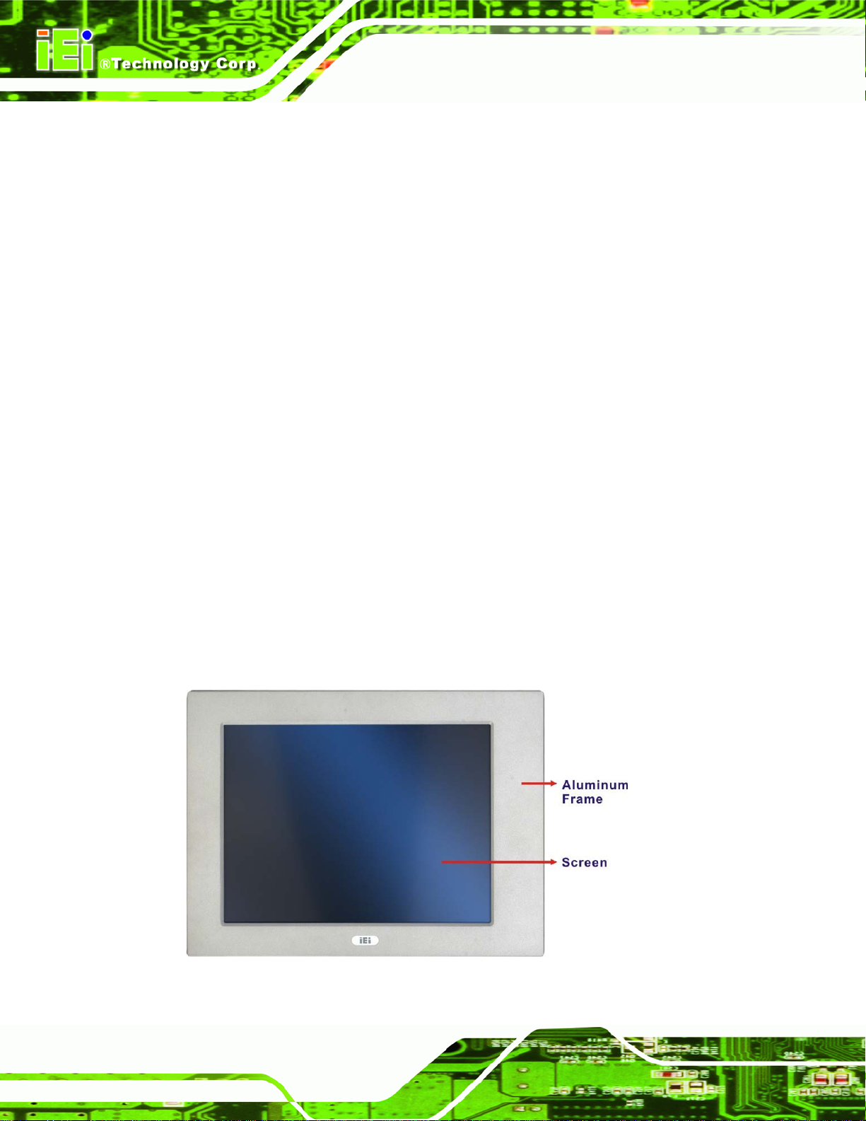
Figure 1-2: Front View....................................................................................................................4
Figure 1-3: Rear View.....................................................................................................................5
Figure 1-4: Top View.......................................................................................................................5
Figure 1-5: PPC-5150A-H61/PPC-5170A-H61 Bottom View........................................................7
Figure 1-6: PPC-5190A-H61 Bottom View ....................................................................................8
Figure 1-7: Left View.......................................................................................................................9
Figure 1-8: Right View....................................................................................................................9
Figure 1-9: Internal Components................................................................................................10
Figure 1-10: PPC-5150A-H61 Dimensions (mm)........................................................................11
Figure 1-11: PPC-5170A-H61 Dimensions (mm)........................................................................12
Figure 1-12: PPC-5190A-H61 Dimensions (mm)........................................................................13
Figure 3-1: PPC-5150A-H61 Back Cover Retention Screws.....................................................25
Figure 3-2: COM1 to COM5 Pin 9 Setting Jumper Locations...................................................28
Figure 3-3: COM5 RS-232/422/485 Serial Port Selection Jumper Location............................29
Figure 3-4: HDD Bracket Retention Screws...............................................................................30
Figure 3-5: HDD Retention Screws.............................................................................................31
Figure 3-6: Replacing the HDD Bracket .....................................................................................31
Figure 3-7: CompactFlash® Cover Plate....................................................................................32
Figure 3-8: Installing the CompactFlash® Card........................................................................32
Figure 3-9: Replacing the CompactFlash® Cover Plate...........................................................33
Figure 3-10: Optical Drive Bracket Retention Screws ..............................................................34
Figure 3-11: Optical Drive Blank Plate Assembly .....................................................................34
Figure 3-12: Optical Drive Screws ..............................................................................................35
Figure 3-13: Optical Drive SATA Cable ......................................................................................35
Figure 3-14: Replacing the Optical Drive Bracket.....................................................................36
Figure 3-15: Installing the PCI Riser Card..................................................................................38
Figure 3-16: Expansion Slot Retention Screw...........................................................................38
Figure 3-17: Installing the PCI Card............................................................................................39
Figure 3-18: Installing the PCIe Riser Card................................................................................41
Figure 3-19: Expansion Slot Retention Screw...........................................................................41
Page x
Page 11

PPC-51xxA-H61 Panel PC
Figure 3-20: Installing the PCIe Card..........................................................................................42
Figure 3-21: AT/ATX Mode Selection..........................................................................................42
Figure 3-22: Wall-mounting Bracket...........................................................................................44
Figure 3-23: Mount the Chassis..................................................................................................45
Figure 3-24: Secure the Chassis.................................................................................................46
Figure 3-25: PPC-5150A-H61 Panel Cutout Dimensions ..........................................................47
Figure 3-26: PPC-5170A-H61 Panel Cutout Dimensions ..........................................................47
Figure 3-27: PPC-5190A-H61 Panel Cutout Dimensions ..........................................................47
Figure 3-28: Panel Mounting Clamp Positions..........................................................................48
Figure 3-29: Tighten the Panel Mounting Clamp Screws.........................................................49
Figure 3-30: Arm Mounting Retention Screw Holes..................................................................50
Figure 3-31: Stand Mounting Retention Screw Holes...............................................................51
Figure 3-32: SFP Fiber Module Installation................................................................................52
Figure 3-33: RJ-45 LAN Connector.............................................................................................53
Figure 3-34: LAN Connection......................................................................................................54
Figure 3-35: RS-232 Serial Port...................................................................................................54
Figure 3-36: RS-232 Serial Device Connector ...........................................................................55
Figure 3-37: RS-232/422/485 Serial Port.....................................................................................56
Figure 3-38: RS-232/422/485 Serial Device Connector .............................................................57
Figure 3-39: USB Device Connection.........................................................................................58
Figure 3-40: VGA Connector .......................................................................................................59
Figure 3-41: VGA Connector .......................................................................................................60
Figure 3-42: Driver Menu .............................................................................................................61
Figure 4-1: SO-DIMM Module Locations.....................................................................................64
Figure 4-2: SO-DIMM Module Installation...................................................................................65
Figure 4-3: PPC-5150A-H61 Top Panel Elevated Platform Screws..........................................65
Figure 4-4: PPC-5150A-H61Side Panel Elevated Platform Screws..........................................66
Figure 4-5: PPC-5150A-H61Bottom Panel Elevated Platform Screws.....................................66
Figure 4-6: PPC-5150A-H61Internal Elevated Platform Screws...............................................66
Figure 4-7: PSU Power Cables....................................................................................................67
Figure 4-8: PSU Bottom Panel Retention Screws.....................................................................68
Figure 4-9: PSU Bottom Panel Screws.......................................................................................68
Figure 4-10: System Cooling Fans Motherboard Connector...................................................69
Figure 4-11: System Cooling Fans Left Panel Retention Screws............................................70
Figure 6-1: Main Board Layout Diagram (Front Side)............................................................ 105
Page xi
Page 12

Figure 6-2: Main Board Layout Diagram (Solder Side).......................................................... 106
Figure B-1: IEI One Key Recovery Tool Menu........................................................................ 127
Figure B-2: Launching the Recovery Tool.............................................................................. 132
Figure B-3: Recovery Tool Setup Menu .................................................................................. 132
Figure B-4: Command Prompt ................................................................................................. 133
Figure B-5: Partition Creation Commands.............................................................................. 134
Figure B-6: Launching the Recovery Tool.............................................................................. 136
Figure B-7: Manual Recovery Environment for Windows..................................................... 136
Figure B-8: Building the Recovery Partition........................................................................... 137
Figure B-9: Press Any Key to Continue.................................................................................. 137
Figure B-10: Press F3 to Boot into Recovery Mode............................................................... 138
Figure B-11: Recovery Tool Menu ........................................................................................... 138
Figure B-12: About Symantec Ghost Window........................................................................ 139
Figure B-13: Symantec Ghost Path ......................................................................................... 139
PPC-51xxA-H61 Panel PC
Figure B-14: Select a Local Source Drive ............................................................................... 140
Figure B-15: Select a Source Partition from Basic Drive ...................................................... 140
Figure B-16: File Name to Copy Image to ............................................................................... 141
Figure B-17: Compress Image.................................................................................................. 141
Figure B-18: Image Creation Confirmation............................................................................. 142
Figure B-19: Image Creation Complete................................................................................... 142
Figure B-20: Image Creation Complete................................................................................... 142
Figure B-21: Press Any Key to Continue................................................................................ 143
Figure B-22: Auto Recovery Utility.......................................................................................... 144
Figure B-23: Launching the Recovery Tool............................................................................ 144
Figure B-24: Auto Recovery Environment for Windows ....................................................... 144
Figure B-25: Building the Auto Recovery Partition................................................................ 145
Figure B-26: Factory Default Image Confirmation ................................................................. 145
Figure B-27: Image Creation Complete................................................................................... 146
Figure B-28: Press any key to continue.................................................................................. 146
Figure B-29: Partitions for Linux.............................................................................................. 148
Figure B-30: Manual Recovery Environment for Linux ......................................................... 149
Figure B-31: Access menu.lst in Linux (Text Mode).............................................................. 150
Figure B-32: Recovery Tool Menu ........................................................................................... 150
Figure B-33: Recovery Tool Main Menu.................................................................................. 151
Figure B-34: Restore Factory Default...................................................................................... 152
Page xii
Page 13

PPC-51xxA-H61 Panel PC
Figure B-35: Recovery Complete Window.............................................................................. 153
Figure B-36: Backup System.................................................................................................... 153
Figure B-37: System Backup Complete Window ................................................................... 154
Figure B-38: Restore Backup................................................................................................... 154
Figure B-39: Restore System Backup Complete Window..................................................... 155
Figure B-40: Symantec Ghost Window ................................................................................... 155
Page xiii
Page 14

PPC-51xxA-H61 Panel PC
List of Tables
Table 1-1: Model Variations...........................................................................................................3
Table 1-2: System Specifications................................................................................................16
Table 2-1: Packing List.................................................................................................................19
Table 2-2: Optional Items.............................................................................................................21
Table 3-1: Jumpers.......................................................................................................................26
Table 3-2: Preconfigured Jumpers .............................................................................................27
Table 3-3: COM1 to COM5 Pin 9 Setting Jumper Settings .......................................................28
Table 3-4: COM5 RS-232/422/485 Serial Port Selection Jumper Settings...............................29
Table 3-5: LAN Pinouts ................................................................................................................53
Table 3-6: RJ-45 LAN Connector LEDs ......................................................................................53
Table 3-7: RS-232 Serial Port Pinouts ........................................................................................55
Table 3-8: RS-232/422/485 Serial Port Pinouts..........................................................................56
Table 3-9: USB 2.0 Port Pinouts..................................................................................................57
Table 3-10: USB 3.0 Port Pinouts................................................................................................59
Table 3-11: VGA Connector Pinouts...........................................................................................59
Table 5-1: BIOS Navigation Keys................................................................................................73
Table 6-1: Peripheral Interface Connectors............................................................................ 108
Table 6-2: +12V Power Source Connector ( CPU12V1) Pinouts ........................................... 108
Table 6-3: ATX Power Connector (ATX1) Pinouts.................................................................. 108
Table 6-4: CompactFlash® Card Slot (CF1) Pinouts.............................................................. 109
Table 6-5: DIO Connector (DIO1) Pinouts ............................................................................... 110
Table 6-6: Fan Connector Pinouts........................................................................................... 110
Table 6-7: Fan Connector (I2C_1) Pinouts.............................................................................. 110
Table 6-8: Internal Audio Connector (SPKL1) Pinouts.......................................................... 111
Table 6-9: Internal Audio Connector (SPKR1) Pinouts.......................................................... 111
Table 6-10: Internal Power Button Connector (PWR_SW1) Pinouts .................................... 111
Table 6-11: Internal Power Button Connector (PWR_SW2) Pinouts .................................... 111
Table 6-12: K Type Thermocouple Connectors (K_TYPE1/K_TYPE2) Pinouts................... 112
Table 6-13: LVDS Backlight Connector (INVERTER1) Pinouts............................................. 112
Table 6-14: LVDS Connector (LVDS1) Pinouts....................................................................... 113
Table 6-15: PCIe Mini Card Slot (MINI_PCIE1) Pinouts.......................................................... 114
Page xiv
Page 15

PPC-51xxA-H61 Panel PC
Table 6-16: SATA 3Gb/s Connectors (SATA1/SATA2) Pinouts ............................................ 114
Table 6-17: SATA Power Connectors (JSATA_PWR1/JSATA_PWR2 Pinouts.................... 114
Table 6-18: SATA Power Connectors (JSATA_PWR1/JSATA_PWR2 Pinouts.................... 115
Table 6-19: SMBus Connector (SMBUS_1) Pinouts............................................................... 115
Table 6-20: SPI Flash Connector (JSPI1) Pinouts.................................................................. 115
Table 6-21: Touch Panel Connector ( TOUCH1) Pinouts....................................................... 116
Table 6-22: USB 2.0 Connector (USB1/USB2/USB3/USB4) Pinouts..................................... 116
Table 6-23: Rear Panel Connectors......................................................................................... 117
Table 6-24: RJ-45 LAN Connector Pinouts............................................................................. 117
Table 6-25: RS-232 Serial Port Pinouts ................................................................................... 117
Table 6-26: RS-232/422/485 Serial Port Pinouts..................................................................... 118
Table 6-27: USB 2.0 Connectors (USB_CON2) Pinouts......................................................... 118
Table 6-28: USB 3.0 Connectors (USB_CON1) Pinouts......................................................... 119
Table 6-29: VGA Connector (VGA1) Pinouts .......................................................................... 119
Table 6-30: Preconfigured Jumpers ........................................................................................ 120
Table 6-31: CF Card Power Selection Jumper (JP1) Settings............................................... 120
Table 6-32: CPU Fan Type Selection Jumper (JCPUFAN1) Settings ................................... 120
Table 6-33: Inverter Brightness Voltage Selection Jumper (J_ADJ1) Settings .................. 120
Table 6-34: LCD Power Selection Jumper (JLCD_PWR1) Settings...................................... 121
Table 6-35: Panel Type and Resolution Selection Jumper (JLCD_SET1) Settings............ 121
Table 6-36: Pull High/Low Selection (for RS-422/485 only) Jumper (UART_SEL1) Settings.. 121
Table 6-37: System Fan Type Selection Jumper Settings..................................................... 122
Table 6-38: Touchscreen Selection Jumper (JTOUCH1) Settings........................................ 122
Table 6-39: USB1~USB4 Power Selection Jumpers Settings............................................... 122
Page xv
Page 16
PPC-51xxA-H61 Panel PC
Chapter
1
1 Introduction
Page 1
Page 17
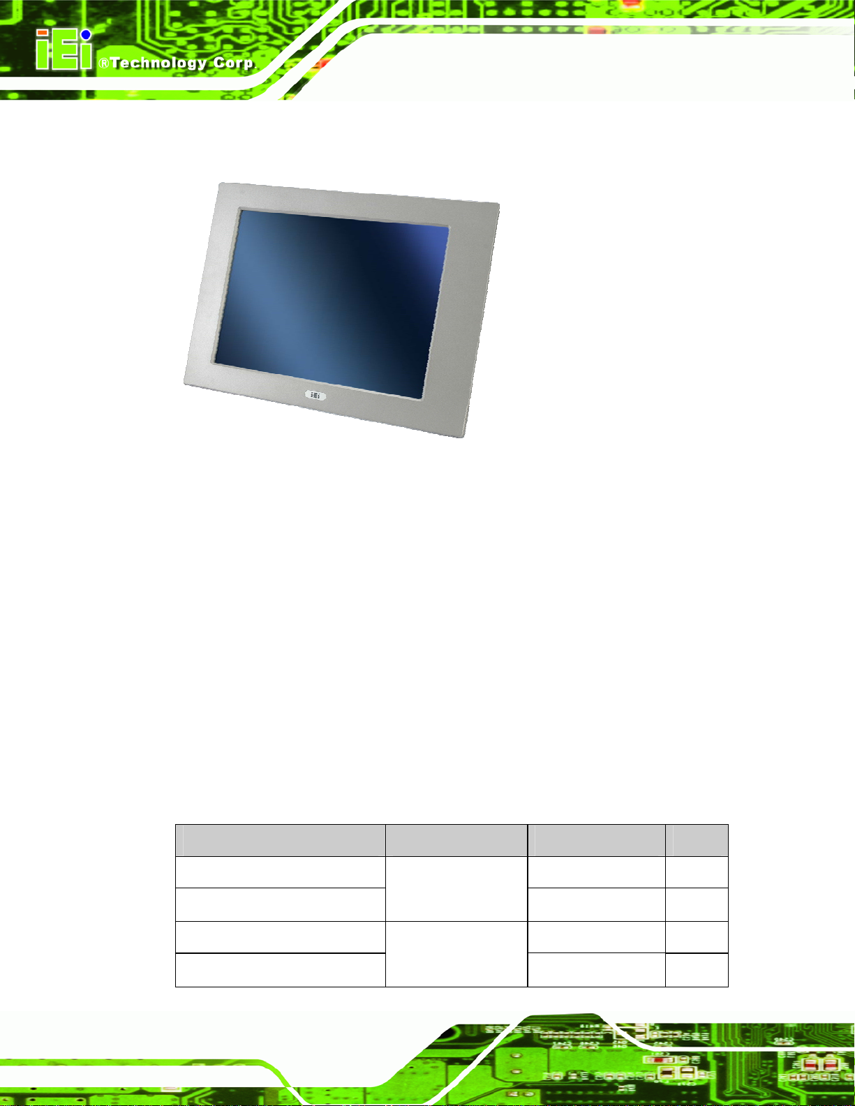
1.1 Overview
Figure 1-1: PPC-51xxA-H61 Panel PC
PPC-51xxA-H61 Panel PC
The PPC-51xxA-H61 panel PC is for industrial environments like production lines and
machine automation. The PPC-51xxA-H61 provides all the features of a PC, combined
with a touch panel screen for mouse and keyboard free data input. The PPC-51xxA-H61
provides wired networking for integration into company networks. The major external
device connections include USB 2.0, USB 3.0 and serial port connectors. Storage options
include a 2.5” hard drive, a CompactFlash® card slot and optional mSATA, allowing for
flexibility in choosing solid state drives or traditional hard drives. A VGA output on the
bottom panel allows the PPC-51xxA-H61 to connect to a second screen for duplicating the
screen contents or extending the user interface.
1.2 Model Variations
The model numbers and model variations are listed below.
Model CPU Power Screen
PPC-5150A-H61-P/R-R10 AC input 15”
PPC-5150AD-H61-P/R-R10
Intel® Pentium®
G6xxT Dual Core
(above 2.2 GHz)
18~36 V DC input 15”
Page 2
PPC-5150A-H61-i3/R-R10 AC input 15”
PPC-5150AD-H61-i3/R-R10
Intel® Core™ i3
2xxxT Dual Core
(above 2.5 GHz)
18~36 V DC input 15”
Page 18
PPC-51xxA-H61 Panel PC
Model CPU Power Screen
PPC-5150A-H61-i5/R-R10 AC input 15”
PPC-5150AD-H61-i5/R-R10
PPC-5170A-H61-P/R-R10 AC input 17”
PPC-5170AD-H61-P/R-R10
PPC-5170A-H61-i3/R-R10 AC input 17”
PPC-5170AD-H61-i3/R-R10
PPC-5170A-H61-i5/R-R10 AC input 17”
PPC-5170AD-H61-i5/R-R10
PPC-5190A-H61-P/R-R10 AC input 19”
PPC-5190AD-H61-P/R-R10
PPC-5190A-H61-i3/R-R10 AC input 19”
PPC-5190AD-H61-i3/R-R10
PPC-5190A-H61-i5/R-R10 AC input 19”
PPC-5190AD-H61-i5/R-R10
Intel® Core™ i5
2xxxT Dual Core
(above 2.7 GHz)
Intel® Pentium®
G6xxT Dual Core
(above 2.2 GHz)
Intel® Core™ i3
2xxxT Dual Core
(above 2.5 GHz)
Intel® Core™ i5
2xxxT Dual Core
(above 2.7 GHz)
Intel® Pentium®
G6xxT Dual Core
(above 2.2 GHz)
Intel® Core™ i3
2xxxT Dual Core
(above 2.5 GHz)
Intel® Core™ i5
2xxxT Dual Core
(above 2.7 GHz)
18~36 V DC input 15”
18~36 V DC input 17”
18~36 V DC input 17”
18~36 V DC input 17”
18~36 V DC input 19”
18~36 V DC input 19”
18~36 V DC input 19”
Table 1-1: Model Variations
1.3 Features
Some of the features of the PPC-51xxA-H61 panel PC include:
Mainstream panel PC design with dual display function.
Aluminum die-casting front panel meet IP 65 water proof standard
High brightness TFT LCD panel with LED backlight
Supports 2nd/3rd generation Intel® Core™, Pentium® and Celeron®
Intel® H61 Express Chipset
Dual DDR3 SO-DIMM (system max. 16 GB)
Multiple storage options: 2.5” SATA HDD, CompactFlash® card and mSATA
Dual Gigabit LAN supporting either RJ-45 or SFP fiber
Optional PCIe Mini 802.11b/g/n wireless module
processors
Page 3
Page 19
Optional PCI/PCIe x1 expansion slot
Supports slim type optical disk drive
Includes the following I/O ports:
o Five COM ports (one RS-232/422/485)
o One CompactFlash® slot
o One VGA port
o RJ-45 and SFP fiber Gigabit LAN ports
o USB 3.0 ports
o USB 2.0 ports
RoHS compliant
1.4 External Overview
The PPC-51xxA-H61 panel PC is comprised of an LCD screen, aluminum front panel and
heavy duty steel rear and side panels. The rear panel provides screw holes for wall and an
PPC-51xxA-H61 Panel PC
arm mounting. The right panel provides access to a slim type optical disk drive bay. The
bottom panel provides access to external interface connectors that include GbE, USB 3.0,
USB 2.0, audio, serial port connectors, VGA port and a CompactFlash® card slot.
1.4.1 Front Panel
The front panel of the PPC-51xxA-H61 (Figure 1-2) is a flat panel TFT LCD screen
surrounded by an aluminum frame.
Page 4
Figure 1-2: Front View
Page 20
PPC-51xxA-H61 Panel PC
1.4.2 Rear Panel
The rear panel has a fan vent, four VESA standard mounting holes and several retention
screw holes. The VESA mounting holes are circled in
Figure 1-3: Rear View
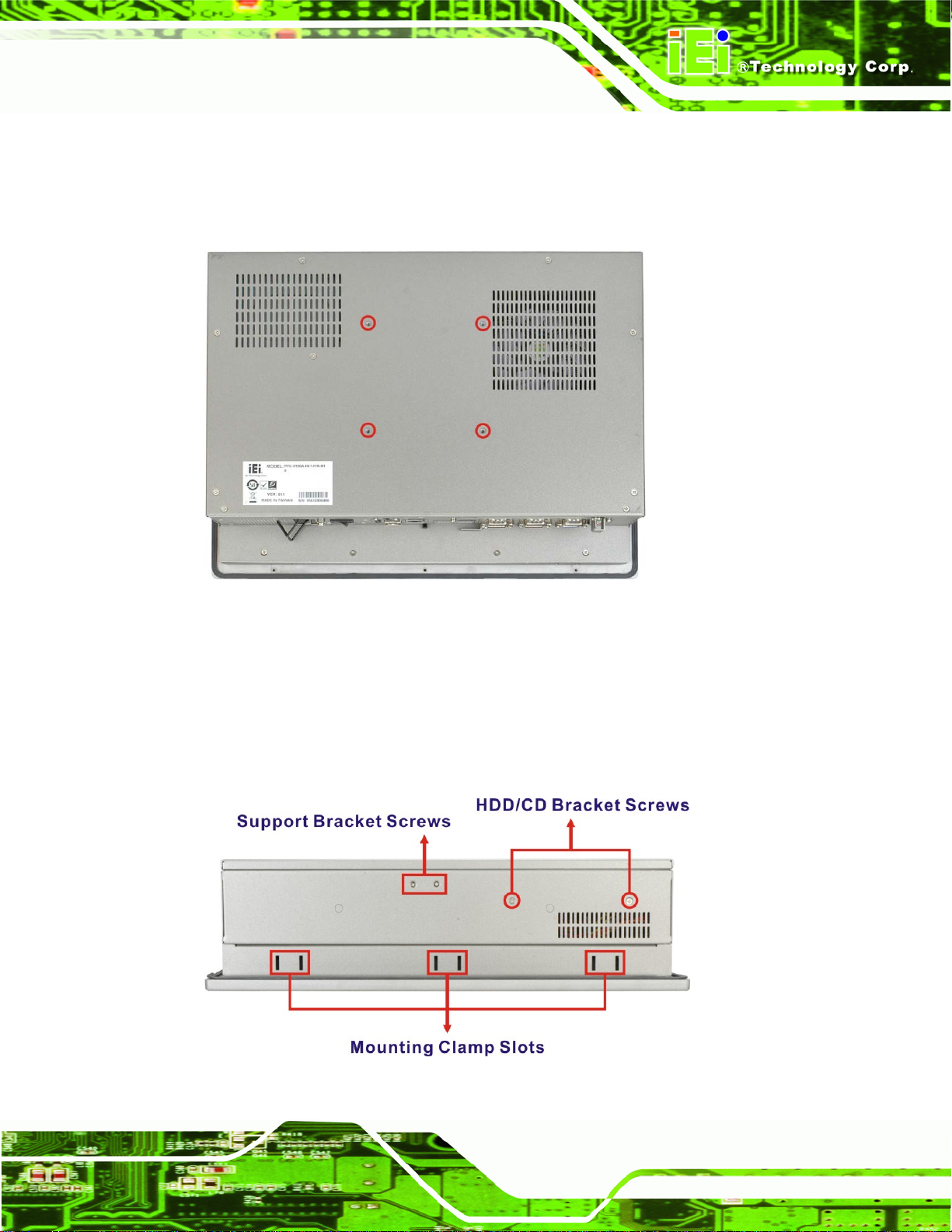
1.4.3 Top Panel
Figure 1-3.
The top panel has panel mounting clamp slots, a fan vent and retention screws for
securing the drive bay bracket. The numbers and locations of the panel mounting clamp
slots may vary by models.
Figure 1-4: Top View
Page 5
Page 21

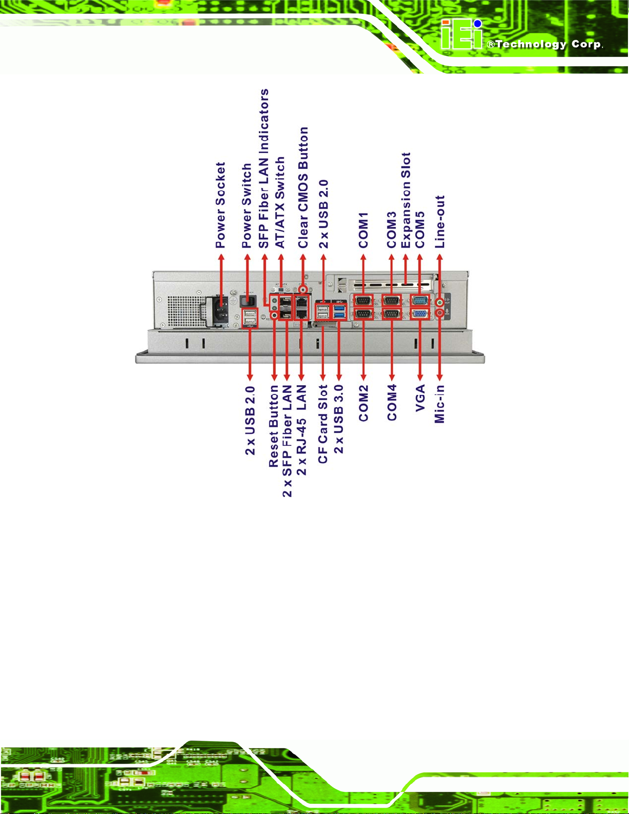
1.4.4 Bottom Panel
The bottom panel has the following interfaces:
1 x Power input connector
1 x Power switch
2 x USB 3.0 connectors
4 x USB 2.0 connectors (six USB 2.0 ports for PPC-5190A-H61)
1 x Reset button
1 x Clear CMOS button
2 x RJ-45 GbE connectors
2 x SFP fiber Gigabit LAN connectors
4 x RS-232 connectors (COM1, COM2, COM3 and COM4)
1 x RS-232/422/485 connector (COM5)
1 x PCI/PCIe x1 expansion card slot
PPC-51xxA-H61 Panel PC
1 x Line-out jack
1 x Mic-in jack
1 x VGA connector
1 x CompactFlash® card slot
1 x AT/ATX switch
2 x SFP fiber indicators
Page 6
Page 22
PPC-51xxA-H61 Panel PC
Figure 1-5: PPC-5150A-H61/PPC-5170A-H61 Bottom View
Page 7
Page 23
PPC-51xxA-H61 Panel PC
Page 8
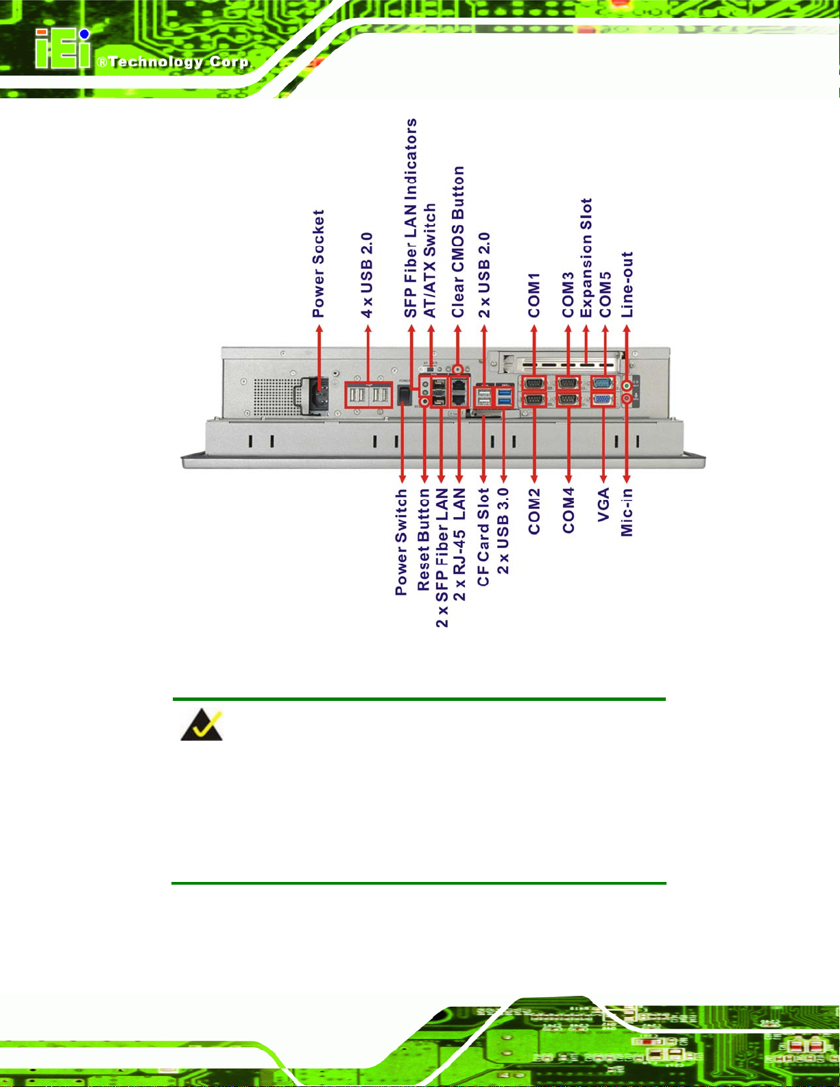
Figure 1-6: PPC-5190A-H61 Bottom View
NOTE:
The PPC-51xxA-H61 provides two types of Gigabit LAN, one is SFP
fiber and the other is RJ-45. The user can use either one of it. When a
SFP fiber LAN port is linked, the corresponding SFP fiber indicator
lights up.
Page 24
PPC-51xxA-H61 Panel PC
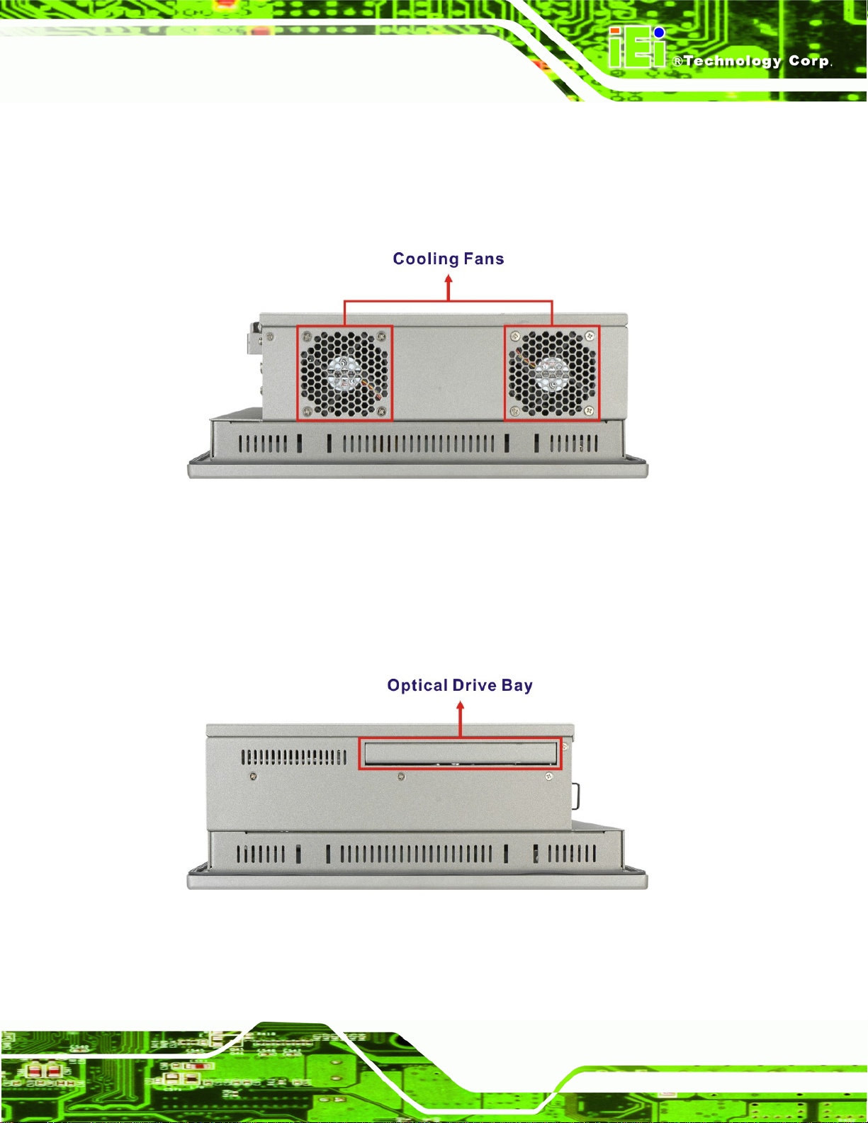
1.4.5 Left Panel
The left panel has two cooling fans that cool the interior of the system and slots for
installing the panel mounting clamps. The numbers and locations of the panel mounting
clamp slots may vary by models.
Figure 1-7: Left View
1.4.6 Right Panel
The right panel has a slim type optical disk drive bay for ODD installation and slots for
installing the panel mounting clamps. The numbers and locations of the panel mounting
clamp slots may vary by models.
Figure 1-8: Right View
Page 9
Page 25
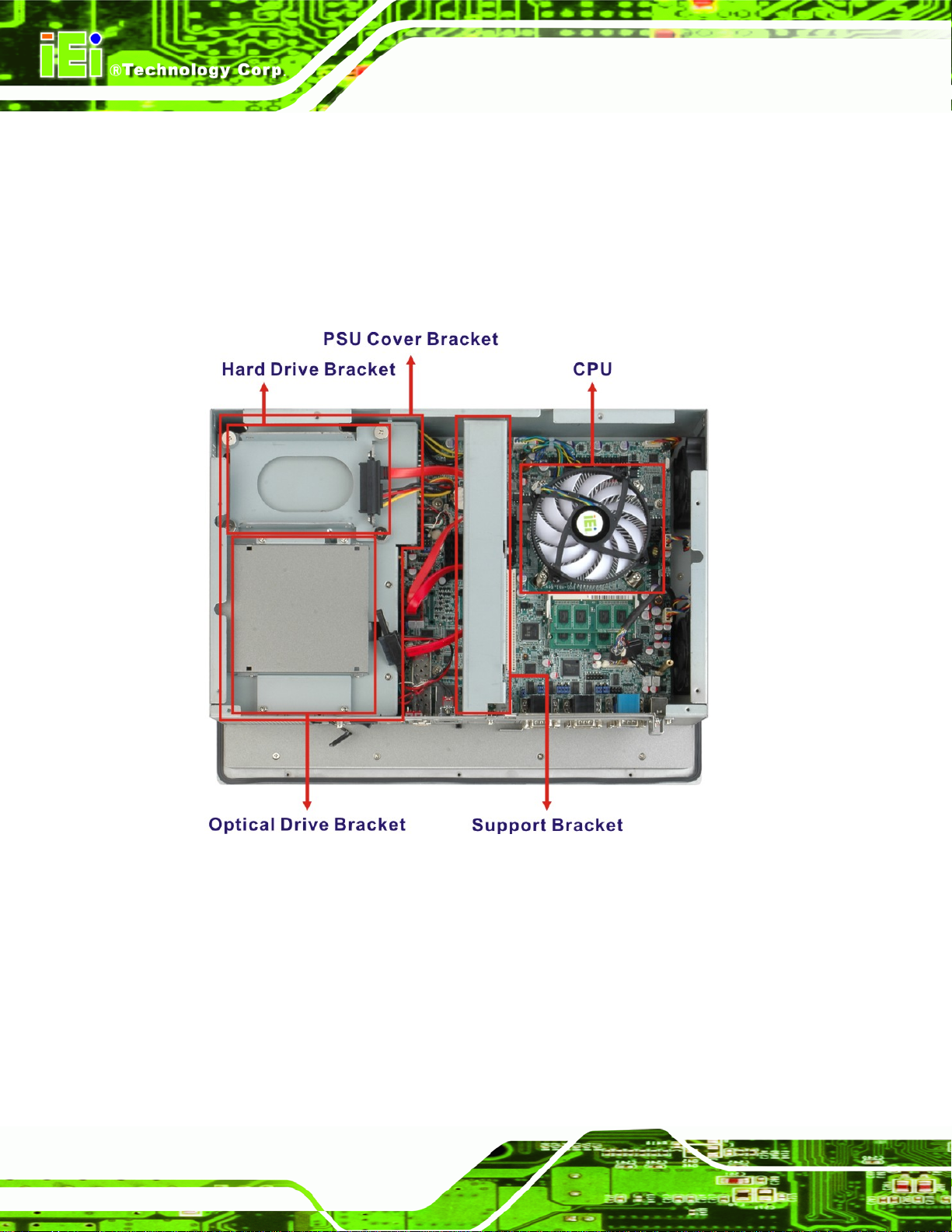
1.5 Internal Overview
The PPC-51xxA-H61 internal components are configured in three levels. The PSU cover
PPC-51xxA-H61 Panel PC
bracket to the left (
7Figure 1-9) supports the hard drive and optical drive brackets. Below
the PSU cover bracket is the power supply. On the same level as the power supply is the
motherboard. Below the motherboard and PSU level is an LCD panel. An overview picture
of the internal components is shown in
7Figure 1-9 below.
Page 10
Figure 1-9: Internal Components
Page 26
PPC-51xxA-H61 Panel PC
1.6 Dimensions
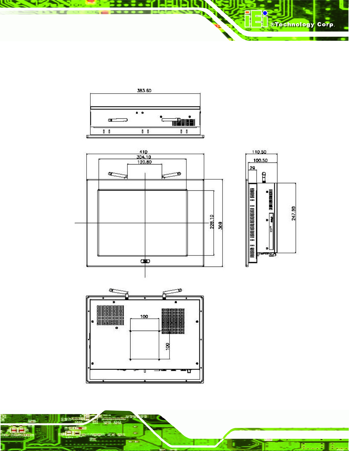
1.6.1 PPC-5150A-H61 Dimensions
Figure 1-10: PPC-5150A-H61 Dimensions (mm)
Page 11
Page 27
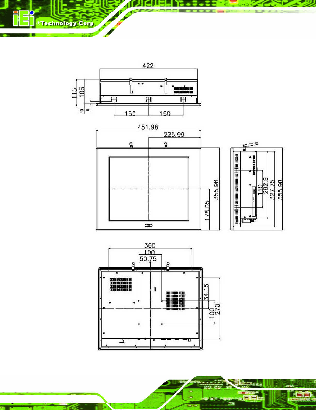
1.6.2 PPC-5170A-H61 Dimensions
PPC-51xxA-H61 Panel PC
Page 12
Figure 1-11: PPC-5170A-H61 Dimensions (mm)
Page 28
PPC-51xxA-H61 Panel PC
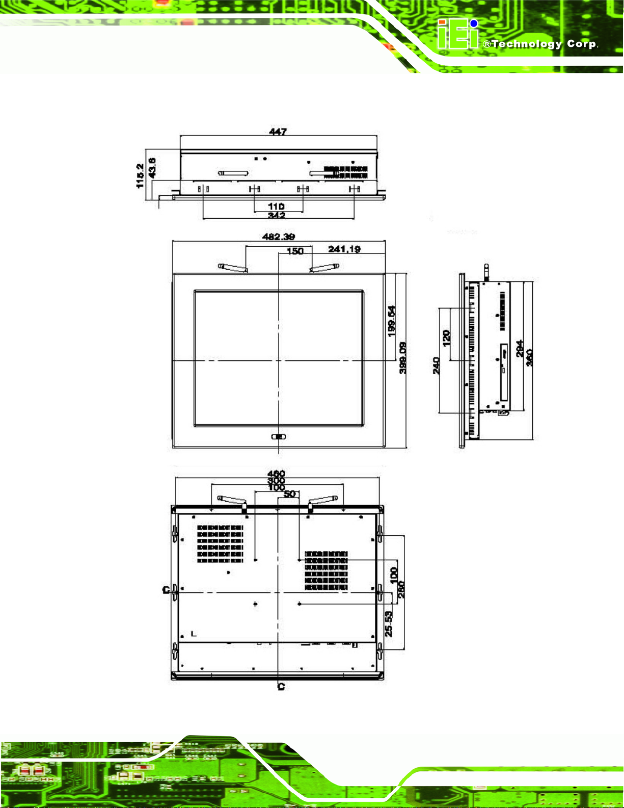
1.6.3 PPC-5190A-H61 Dimensions
Figure 1-12: PPC-5190A-H61 Dimensions (mm)
Page 13
Page 29
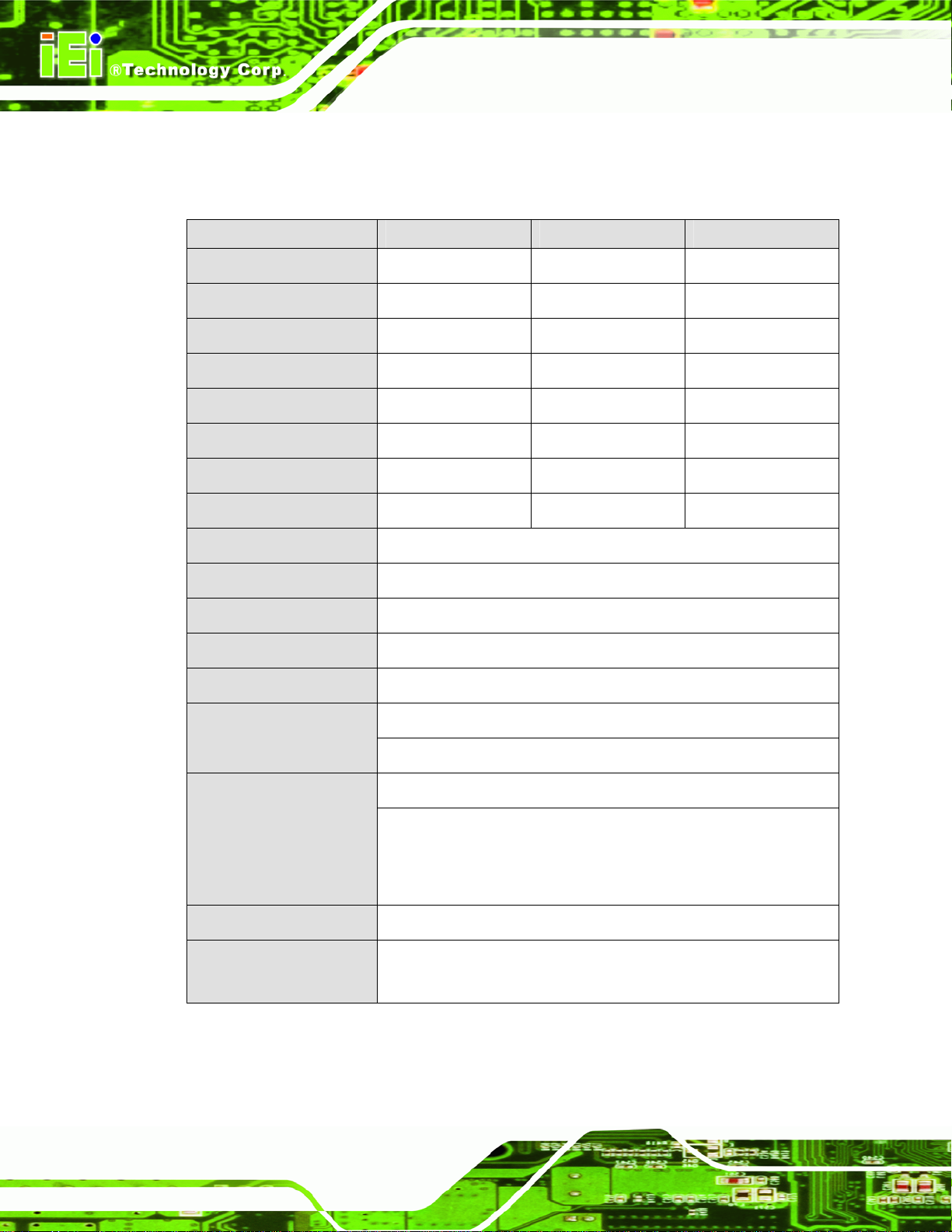
1.7 Specifications
The technical specifications for the PPC-51xxA-H61 system are listed in Table 1-2.
PPC-5150A-H61 PPC-5170A-H61 PPC-5190A-H61
PPC-51xxA-H61 Panel PC
LCD Size
Max. Resolution
Brightness
Contrast Ratio
Pixel Pitch (mm)
Viewing Angle (V-H)
LCD Color
Backlight MTBF
SBC Model
CPU
Express Chipset
Memory
Solid State Drive (SSD)
15” 17” 19”
1024 (W) x 768 (H) 1280 (W) x 1024 (H) 1280 (W) x 1024 (H)
400 cd/m
700:1 800:1 1000:1
0.297 x 0.297 0.264 x 0.264 0.294 x 0.294
140/160 170/160 160/170
16.2M 16.7M 16.7M
50,000 hours 50,000 hours 50,000 hours
POS-H61
2nd/3rd generation Intel® Core™, Pentium® or Celeron® CPU
Intel® H61
Two 204-pin DDR3 SO-DIMM slots (system max. 16 GB)
CompactFlash® Type II and mSATA (optional)
2
350 cd/m2 350 cd/m2
Page 14
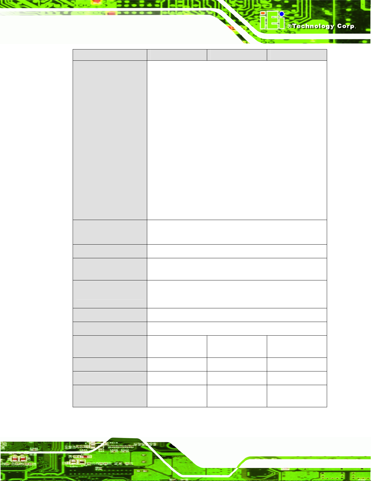
Drive Bays
Expansion Slots
Touchscreen
Wireless LAN
One 2.5” SATA HDD bay with anti-shock
One slim type optical disk drive bay
One PCIe Mini
Optional riser card:
One PCI or
One PCIe x4 with PCIe x1 signal
5-wire resistive type with RS-232 interface
IEEE 802.11b/g/n 2T2R mode WLAN via internal PCIe Mini card
(optional)
Page 30
PPC-51xxA-H61 Panel PC
PPC-5150A-H61 PPC-5170A-H61 PPC-5190A-H61
I/O Ports, Switches and
Indicators
2 x USB 3.0
4 x USB 2.0 (six USB 2.0 ports for PPC-5190A-H61 series)
4 x RS-232 (COM1 ~ COM4)
1 x RS-232/422/485 (COM5)
2 x PS/2 for keyboard and mouse
1 x VGA connector
2 x RJ-45 LAN connectors
2 x SFP fiber LAN connectors
2 x Audio jacks (Line-out and Mic-in)
1 x CMOS reset button
1 x AT/ATX switch
1 x Power switch
Mounting
Chassis Construction
Front Panel
Construction
Vibration
Shock
Humidity
Operating Temperature
(Ambient with air flow)
Storage Temperature
Net/Gross Weight
2 x SFP fiber LAN indicators
VESA 100 mm x 100 mm
(panel, wall, rack, stand and arm)
Heavy-duty steel
Aluminum
5 Hz ~ 17 Hz 0.1” double amplitude displacement
17 Hz ~ 640 Hz 1.5G acceleration peak to peak
10G acceleration part to part (11 ms)
10% ~ 95%, non-condensing
-20ºC ~ 60ºC -20ºC ~ 60ºC -10ºC ~ 50ºC
-30ºC ~ 70ºC -30ºC ~ 70ºC -20ºC ~ 60ºC
7 kg/11 kg 8 kg/12 kg 12.6 kg/18.2 kg
Dimensions
(W x H x D) (mm)
410 x 309 x 110.5 452 x 356 x 115 482 x 399 x 115
Page 15
Page 31

PPC-5150A-H61 PPC-5170A-H61 PPC-5190A-H61
ACE-A622A-RS
PPC-51xxA-H61 Panel PC
AC Input ATX
(A Model)
DC Input ATX
(AD Model)
Table 1-2: System Specifications
220 W
Input: 90 V AC~264 V AC, 50/60 Hz
Output (max.): 3.3 A@14 A, 5 V@16 A, 12 V@10 A,
-12 V@0.8 A
ACE-4520C-RS
200 W
Input: 24 V DC (18~36 V DC), 50/60 Hz
-Output (max.): 3.3 A@12 A, 5 V@12 A, 12 V@15.4 A,
-12 V@0.5 A
Page 16
Page 32

PPC-51xxA-H61 Panel PC
Chapter
2
2 Unpacking
Page 17
Page 33

2.1 Unpacking
To unpack the panel PC, follow the steps below:
WARNING!
The front side LCD screen has a protective plastic cover stuck to the
screen. Only remove the plastic cover after the panel PC has been properly
installed. This ensures the screen is protected during the installation
process.
Step 1: Use box cutters, a knife or a sharp pair of scissors that seals the top side of the
external (second) box.
PPC-51xxA-H61 Panel PC
Step 2: Open the external (second) box.
Step 3: Use box cutters, a knife or a sharp pair of scissors that seals the top side of the
internal (first) box.
Step 4: Lift the monitor out of the boxes.
Step 5: Remove both polystyrene ends, one from each side.
Step 6: Pull the plastic cover off the panel PC.
Step 7: Make sure all the components listed in the packing list are present. Step 0:
Page 18
Page 34

PPC-51xxA-H61 Panel PC
2.2 Packing List
The PPC-51xxA-H61 panel PC is shipped with the following components:
Quantity Item Image
1 PPC-51xxA-H61
1 SATA CD-ROM cable
(P/N: 32803-000300-100-RS)
1 Power cord
(P/N: 32000-000002-RS)
1 Panel mounting kit
(P/N: 19Z00-000024-RS)
1 Wall mounting kit
(P/N: 41020-016102-00-RS)
1 Touch pen
1 User manual and driver CD
1
One Key Recovery CD
(P/N: IEI-7B000-000478-RS)
Table 2-1: Packing List
If any of the above items are missing or damaged, contact the distributor or sales
representative immediately.
Page 19
Page 35

2.3 Optional Items
The following items are optional accessories for the PPC-51xxA-H61:
Item Image
Slim type SATA DVD-ROM
(P/N: 73400-AD7760H01-RS)
1-slot PCI riser card
(P/N: PCIR-01H-R10)
1-slot PCIe x1 riser card
(P/N: PCIER-101H-R10)
PPC-51xxA-H61 Panel PC
Arm
(P/N: ARM-31-RS)
Stand
(P/N: STAND-210-R11)
Gigabit Ethernet SFP fiber module
(P/N: SFP1G-SX/-I
SFP1G-MLX/-I
SFP1G-LX10/-I
SFP1G-ZX70/-I)
Page 20
Page 36

PPC-51xxA-H61 Panel PC
Item Image
Rack mounting kit
(P/N: RK-150MS-R10
RK-170MS-R10
RK-190MS-R10)
Wi-Fi module with RF cable and antenna for
PPC-5150A-H61/PPC-5170A-H61, 2T2R,
802.11b/g/n
(P/N: PPC-WL-KIT02-R10)
Wi-Fi module with RF cable and antenna for
PPC-5190A-H61, 2T2R, 802.11b/g/n
(P/N: PPC-WL-KIT03-R10)
Table 2-2: Optional Items
Page 21
Page 37

PPC-51xxA-H61 Panel PC
3 Installation
Chapter
3
Page 22
Page 38

PPC-51xxA-H61 Panel PC
3.1 Anti-static Precautions
WARNING:
Failure to take ESD precautions during the maintenance of the EP
series may result in permanent damage to the EP series and severe
injury to the user.
Electrostatic discharge (ESD) can cause serious damage to electronic components,
including the PPC-51xxA-H61. Dry climates are especially susceptible to ESD. It is
therefore critical that whenever the PPC-51xxA-H61 is accessed internally, or any other
electrical component is handled, the following anti-static precautions are strictly adhered
to.
Wear an anti-static wristband: - Wearing a simple anti-static wristband can
help to prevent ESD from damaging the board.
Self-grounding: - Before handling the board touch any grounded conducting
material. During the time the board is handled, frequently touch any
conducting materials that are connected to the ground.
Use an anti-static pad: - When configuring the PPC-51xxA-H61, place it on
an antic-static pad. This reduces the possibility of ESD damaging the
PPC-51xxA-H61.
Only handle the edges of the PCB: - When handling the PCB, hold the PCB
by the edges.
3.2 Installation Precautions
When installing the panel PC, please follow the precautions listed below:
Power turned off: When installing the panel PC, make sure the power is off.
Failing to turn off the power may cause severe injury to the body and/or
damage to the system.
Certified Engineers: Only certified engineers should install and modify
onboard functionalities.
Page 23
Page 39

Mounting: The PPC-51xxA-H61 is a heavy device. When mounting the
system onto a rack, panel, wall or arm, please make sure that at least two
people are assisting with the procedure.
Anti-static Discharge : If a user open the rear panel of the panel PC, to
configure the jumpers or plug in added peripheral devices, ground themselves
first and wear and anti-static wristband.
3.3 Preinstalled Components
The following components are all preinstalled.
Motherboard
DDR3 memory module
TFT LCD
Touchscreen
PPC-51xxA-H61 Panel PC
Power supply
Inverter board
System cooling fans
Preinstalled OEM customizations may include the following.
CPU
HDD
Wi-Fi module
Optical disk drive
PCI/PCIe x1 riser card
3.4 Installation and Configuration Steps
The following installation steps must be followed.
Step 1: Unpack the PPC-51xxA-H61.
Step 2: Set the jumper settings.
Page 24
Step 3: Install HDD, CompactFlash® card and optical disk drive.
Step 4: Mount the PPC-51xxA-H61 panel PC.
Page 40

PPC-51xxA-H61 Panel PC
Step 5: Connect peripheral devices to the bottom panel of the PPC-51xxA-H61.
Step 6: Configure the system.Step 0:
3.5 Removing the Back Cover
Remove all the retention screws on the back cover. Lift the cover up to remove.
Figure 3-1: PPC-5150A-H61 Back Cover Retention Screws
Page 25
Page 41

3.6 Jumper Settings
NOTE:
A jumper is a metal bridge used to close an
electrical circuit. It consists of two or three metal
pins and a small metal clip (often protected by a
plastic cover) that slides over the pins to connect
them. To CLOSE/SHORT a jumper means
connecting the pins of the jumper with the plastic
clip and to OPEN a jumper means removing the
plastic clip from a jumper.
The following jumpers can be found on the motherboard installed in the PPC-51xxA-H61.
PPC-51xxA-H61 Panel PC
Before the PPC-51xxA-H61 is installed, the jumpers must be set in accordance with the
desired configuration. The jumpers on the PPC-51xxA-H61 motherboard are listed in
7Table 3-1.
Description Label Type
COM1 Pin 9 setting J_COM_V1 6-pin header
COM2 Pin 9 setting J_COM_V2 6-pin header
COM3 Pin 9 setting J_COM_V3 6-pin header
COM4 Pin 9 setting J_COM_V4 6-pin header
COM5 Pin 9 setting J_COM_V5 6-pin header
COM5 RS-232/422/485 selection JP2 4-pin header
Table 3-1: Jumpers
3.6.1 Access the Jumpers
Page 26
To access the jumpers, remove the back cover. To remove the back cover, please refer to
Section
73.5.
Page 42

PPC-51xxA-H61 Panel PC
3.6.2 Preconfigured Jumpers
WARNING:
Do not change the settings on the jumpers in described here. Doing so
may disable or damage the system
The following jumpers are preconfigured for the PPC-51xxA-H61. Users should not
change these jumpers.
Jumper Name Label Type
CF card power selection JP1 3-pin header
Inverter brightness voltage
J_ADJ1 3-pin header
selection
LCD power selection JLCD_PWR1 6-pin header
Panel type and resolution
JLCD_SET1 8-pin header
selection
Touchscreen selection JTOUCH1 4-pin header
USB1~USB4 power selection USBAB_PWR1,
3-pin header
USB01_PWR1,
USB23_PWR1,
USB45_PWR1
Table 3-2: Preconfigured Jumpers
3.6.3 COM1 to COM5 Pin 9 Setting Jumpers
Jumper Label: J_COM_V1, J_COM_V2, J_COM_V3, J_COM_V4 and
J_COM_V5
Jumper Type:
Jumper Settings:
Jumper Location:
6-pin header
7Table 3-3
See
7Figure 3-2
See
Page 27
Page 43

PPC-51xxA-H61 Panel PC
Five jumpers configure pin 9 on the COM1, COM2, COM3 COM4 and COM5 connectors.
Pin 9 on these connectors can be set as either +5 V, +12 V or as the ring (RI) signal. The
COM1, COM2, COM3, COM4 and COM5 Pin 9 setting jumper selection options are
shown in
Serial Port
J_COM_V1 COM1 RI signal +5 V Pin 9 power +12 V
J_COM_V2 COM2 RI signal +5 V Pin 9 power +12 V
J_COM_V3 COM3 RI signal +5 V Pin 9 power +12 V
J_COM_V4 COM4 RI signal +5 V Pin 9 power +12 V
J_COM_V5 COM5 RI signal +5 V Pin 9 power +12 V
7Table 3-3.
Short 1 – 3 Short 2 - 4
Default
Default
Short
3 – 5
Short
4 – 6
Table 3-3: COM1 to COM5 Pin 9 Setting Jumper Settings
The COM1 to COM5 Pin 9 setting jumper locations are shown in 7Figure 3-2 below.
Page 28
Figure 3-2: COM1 to COM5 Pin 9 Setting Jumper Locations
Page 44

PPC-51xxA-H61 Panel PC
3.6.4 COM5 RS-232/422/485 Serial Port Selection Jumper
Jumper Label: JP2
Jumper Type:
Jumper Settings:
Jumper Location:
4-pin header
Table 3-4
See
Figure 3-3
See
The COM5 RS-232/422/485 Serial Port Selection jumper sets the communication protocol
used by the COM5 serial communications port as RS-232, RS-422 or RS-485. The COM5
RS-232/422/485 Serial Port Selection settings are shown in
COM5 Mode Pin 1-2 Pin 3-4
RS-232 (Default) Short Open
RS-422 Short Short
RS-485 (Default: RX) Open Short
RS-485 (Default: TX) Open Open
7Table 3-4.
Table 3-4: COM5 RS-232/422/485 Serial Port Selection Jumper Settings
The COM5 RS-232/422/485 Serial Port Select jumper location is shown in Figure 3-3.
Figure 3-3: COM5 RS-232/422/485 Serial Port Selection Jumper Location
Page 29
Page 45

3.7 Drive Installation
The drive installation process is shown in the sections below.
3.7.1 Hard Drive Installation
To install a HDD, please follow the steps below:
PPC-51xxA-H61 Panel PC
Step 1: Remove the back cover (Section
73.5).
Step 2: The HDD bracket is attached to the elevated platform by four retention screws.
Remove the four retention screws from the elevated platform (
7Figure 3-4).
Page 30
Figure 3-4: HDD Bracket Retention Screws
Step 3: Attach the hard drive in the bracket. To do this, slide the hard drive onto the
bracket until it connects with the SATA connector at the back. Fasten the four
retention screws on the side.
Page 46

PPC-51xxA-H61 Panel PC
Figure 3-5: HDD Retention Screws
Step 4: Install the hard drive bracket (with hard drive and SATA cable attached) into the
PPC-51xxA-H61 and fasten the four hard drive bracket screws.Step 0:
Figure 3-6: Replacing the HDD Bracket
Page 31
Page 47

3.7.2 CompactFlash® Card Installation
To install the CompactFlash® card, please follow the steps below:
Step 1: Undo the CompactFlash® slot cover screw and remove the CompactFlash®
cover plate.
PPC-51xxA-H61 Panel PC
Figure 3-7: CompactFlash® Cover Plate
Step 2: Insert the CompactFlash® card into the slot.
Figure 3-8: Installing the CompactFlash® Card
Page 32
Page 48

PPC-51xxA-H61 Panel PC
Step 3: Replace the CompactFlash® cover plate.Step 0:
Figure 3-9: Replacing the CompactFlash® Cover Plate
3.7.3 Optical Disk Drive Installation (Optional)
To install an optical disk drive, please follow the steps below.
Step 1: Remove the back cover (Section
Step 2: Undo the optical drive bracket screws and remove the optical drive bracket.
73.5).
Page 33
Page 49

Figure 3-10: Optical Drive Bracket Retention Screws
PPC-51xxA-H61 Panel PC
Step 3: Remove the four screws from the optical drive bracket assembly (
Remove the blank drive plate.
Figure 3-11: Optical Drive Blank Plate Assembly
Figure 3-11).
Page 34
Step 4: Install the optical drive in the same position as the previously removed blank
optical drive plate. Fasten the same four screws to attach the optical drive to the
bracket.
Page 50

PPC-51xxA-H61 Panel PC
Figure 3-12: Optical Drive Screws
Step 5: Attach the SATA cable to the back of the optical drive and fasten the SATA cable
screws.
Figure 3-13: Optical Drive SATA Cable
Step 6: Reinstall the optical drive bracket into the PPC-51xxA-H61 and fasten the optical
bracket screws.Step 0:
Page 35
Page 51

Figure 3-14: Replacing the Optical Drive Bracket
PPC-51xxA-H61 Panel PC
Page 36
Page 52

PPC-51xxA-H61 Panel PC
3.8 PCI Expansion Card Installation (Optional)
NOTE:
The expansion card cannot exceed the dimensions shown below.
To install a PCI expansion card, please do the following.
Step 1: Remove the back cover. See Section
Step 2: Install the PCI riser card. Insert the PCI riser card into the PCI slot on the
motherboard of the system. Secure the PCI riser card to the system with two
retention screws.
73.5.
Page 37
Page 53

Figure 3-15: Installing the PCI Riser Card
Step 3: Remove the expansion slot cover. The expansion slot on the I/O panel
PPC-51xxA-H61 Panel PC
interface is secured to the system with a single retention screw. Remove the
screw (
Figure 3-16: Expansion Slot Retention Screw
Step 4: Insert the expansion card. Align the PCI expansion card edge connector with
Figure 3-16).
Page 38
the PCI expansion slot on the PCI riser card. Gently insert the PCI card into the
PCI expansion slot.
Page 54

PPC-51xxA-H61 Panel PC
Step 5: Secure the expansion card. Once the PCI card is correctly installed in the
system, reinsert the previously removed retention screw to secure the card to
the I/O interface panel.
Figure 3-17: Installing the PCI Card
Page 39
Page 55

PPC-51xxA-H61 Panel PC
3.9 PCIe Expansion Card Installation (Optional)
NOTE:
The expansion card cannot exceed the dimensions shown below.
Page 40
To install a PCIe expansion card, please do the following.
Step 1: Remove the back cover. See Section
Step 2: Install the PCIe riser card. Insert the PCIe riser card into the PCI slot and PCIe
x4 slot on the motherboard of the system. Secure the PCIe riser card to the
system with two retention screws.
73.5.
Page 56

PPC-51xxA-H61 Panel PC
Figure 3-18: Installing the PCIe Riser Card
Step 3: Remove the expansion slot cover. The expansion slot on the I/O panel
interface is secured to the system with a single retention screw. Remove the
screw.
Figure 3-19: Expansion Slot Retention Screw
Step 4: Insert the expansion card. Align the PCIe expansion card edge connector with
the PCIe expansion slot on the PCIe riser card. Gently insert the PCIe card into
the PCIe expansion slot.
Page 41
Page 57

Step 5: Secure the expansion card. Once the PCIe card is correctly installed in the
system, reinsert the previously removed retention screw to secure the card to
the I/O interface panel.Step 0:
PPC-51xxA-H61 Panel PC
Figure 3-20: Installing the PCIe Card
3.10 AT/ATX Mode Selection
AT and ATX power modes can both be used on the PPC-51xxA-H61 panel PC. The
selection is made through an AT/ATX switch on the I/O interface panel. The switch is
shown below.
Figure 3-21: AT/ATX Mode Selection
Page 42
Page 58

PPC-51xxA-H61 Panel PC
3.11 Mounting the System
WARNING!
When mounting the PPC-51xxA-H61 panel PC, it is advisable to have
more than one person help with the installation to prevent accidental
damage to the panel and avoid personal injury.
The methods of mounting the PPC-51xxA-H61 are:
Wall mounting
Panel mounting
Arm mounting
Stand mounting
Rack mounting
The mounting methods are described in the following sections.
3.11.1 Wall Mounting
To mount the PPC-51xxA-H61 panel PC onto a wall, please follow the steps below.
Step 1: Select the location on the wall for the wall-mounting bracket.
Step 2: Carefully mark the locations of the four bracket screw holes on the wall.
Step 3: Drill four pilot holes at the marked locations on the wall for the bracket retention
screws.
Step 4: Align the wall-mounting bracket screw holes with the pilot holes.
Step 5: Secure the mounting bracket to the wall by inserting the retention screws into
the four pilot holes and tightening them (
Figure 3-22).
Page 43
Page 59

Figure 3-22: Wall-mounting Bracket
Step 6: Insert the four monitor mounting screws provided in the wall mounting kit into the
PPC-51xxA-H61 Panel PC
four screw holes on the real panel of the monitor and tighten until the screw
shank is secured against the rear panel (
Step 7: Align the mounting screws on the monitor rear panel with the mounting holes on
the bracket.
Step 8: Carefully insert the screws through the holes and gently pull the monitor
downwards until the monitor rests securely in the slotted holes (
Ensure that all four of the mounting screws fit snuggly into their respective
slotted holes.
Figure 3-23).
Figure 3-23).
NOTE:
In the diagram below the bracket is already installed on the wall.
Page 44
Page 60

PPC-51xxA-H61 Panel PC
Figure 3-23: Mount the Chassis
Step 9: Secure the panel PC with the wall-mounting kit. To do this, stick the protective
cushion to the wall-mounting kit first. Then, put the wall-mounting kit on the top
panel of the panel PC. Carefully mark the location of the wall-mounting kit screw
holes on the wall. Drill a pilot hole at the marked location on the wall. Secure the
wall-mounting kit to the wall by inserting a retention screw into the pilot hole on
the wall (
7Figure 3-24). This step is to avoid the panel PC being pushed apart
from the wall-mounting bracket accidentally. Step 0:
Page 45
Page 61

PPC-51xxA-H61 Panel PC
Figure 3-24: Secure the Chassis
3.11.2 Panel Mounting
To mount the PPC-51xxA-H61 panel PC into a panel, please follow the steps below.
NOTE:
The maximum panel thickness should be no more than 6 mm.
Step 1: Select the position on the panel to mount the PPC-51xxA-H61.
Step 2: Cut out a section of the panel that corresponds to the rear panel dimensions of
the PPC-51xxA-H61. The recommended cutout sizes are shown below
7Figure 3-25, 7Figure 3-26 and 7Figure 3-27).
(
Page 46
Page 62

PPC-51xxA-H61 Panel PC
Figure 3-25: PPC-5150A-H61 Panel Cutout Dimensions
Figure 3-26: PPC-5170A-H61 Panel Cutout Dimensions
Figure 3-27: PPC-5190A-H61 Panel Cutout Dimensions
Page 47
Page 63

PPC-51xxA-H61 Panel PC
Step 3: Slide the PPC-51xxA-H61 through the hole until the metal frame is flush against
the panel.
Step 4: Insert the panel mounting clamps into the pre-formed holes along the edges of
the PPC-51xxA-H61, behind the aluminum frame (
7Figure 3-28). Refer to the
mounting kit packing list for the required number of mounting clamps.
Figure 3-28: Panel Mounting Clamp Positions
Step 5: Tighten the screws that pass through the panel mounting clamps until the plastic
Page 48
caps at the front of all the screws are firmly secured to the panel (
7Figure 3-29).
Page 64

PPC-51xxA-H61 Panel PC
Figure 3-29: Tighten the Panel Mounting Clamp Screws
3.11.3 Rack and Cabinet Installation
To mount the PPC-51xxA-H61 into a rack/cabinet, please follow the steps below.
Step 1: Secure the rack mounting bracket to two sides of the monitor using the supplied
retention screws. Each bracket requires four screws.
Step 2: Secure the rack mounting bracket to the rack by inserting and tightening the
supplied mounting nuts and bolts. Each bracket requires three nuts and bolts for
installation.Step 0:
3.11.4 Arm Mounting
The PPC-51xxA-H61 is VESA (Video Electronics Standards Association) compliant and
can be mounted on an arm with a 100 mm interface pad. To mount the PPC-51xxA-H61
on an arm, please follow the steps below.
Step 1: The arm is a separately purchased item. Please correctly mount the arm onto
the surface it uses as a base. To do this, refer to the installation documentation
that came with the mounting arm.
Page 49
Page 65

PPC-51xxA-H61 Panel PC
NOTE:
When purchasing the arm please ensure that it is VESA compliant and
that the arm has a 100 mm interface pad. If the mounting arm is not
VESA compliant, it cannot be used to support the PPC-51xxA-H61
panel PC.
Step 2: Once the mounting arm has been firmly attached to its surface, lift the
PPC-51xxA-H61 panel PC onto the interface pad of the mounting arm.
Step 3: Align the retention screw holes on the mounting arm interface with those in the
PPC-51xxA-H61 panel PC. The arm mounting retention screw holes of the
PPC-51xxA-H61 panel PC are shown in
Figure 3-30: Arm Mounting Retention Screw Holes
Step 4: Secure the PPC-51xxA-H61 to the interface pad by inserting four retention
screws through the mounting arm interface pad and into the PPC-51xxA-H61
Figure 3-30.
panel PC.
3.11.5 Stand Mounting
To mount the PPC-51xxA-H61 using the stand mounting kit, please follow the steps
below.
Page 50
Step 0:
Page 66

PPC-51xxA-H61 Panel PC
Step 1: Locate the screw holes on the rear of the PPC-51xxA-H61. This is where the
bracket will be attached.
Figure 3-31: Stand Mounting Retention Screw Holes
Step 2: Align the bracket with the screw holes.
Step 3: To secure the bracket to the PPC-51xxA-H61, insert the retention screws into
the screw holes and tighten them.Step 0:
3.12 SFP Fiber Module Installation (Optional)
To install the SFP fiber module, please follow the steps below:
Step 1: Locate the SFP fiber connectors. The locations of the connectors are shown in
Figure 1-5 and Figure 1-6.
Step 2: Align the SFP fiber module with one of the SFP fiber connectors on the
PPC-51xxA-H61 (
Step 3: Once aligned, slide the SFP module into place (
7Figure 3-32).
7Figure 3-32).
Page 51
Page 67

Figure 3-32: SFP Fiber Module Installation
PPC-51xxA-H61 Panel PC
NOTE:
The pin locations of the SFP connector 2 are opposite to the SFP
connector 1. Please rotate the SFP module to a proper position to
install the SFP module into the SFP connector 2.
3.13 Bottom Panel Connectors
The bottom panel of the PPC-51xxA-H61 contains I/O connectors, switches and a CF card
slot. Detailed descriptions of the connectors can be found in the subsections below.
3.13.1 Audio Connectors
The audio jacks connect to external audio devices.
Mic-in (Pink): Connects a microphone.
Line-out (Green): Connects to a headphone or a speaker. With multi-channel
Page 52
configurations, this port can also connect to front speakers.
Page 68

PPC-51xxA-H61 Panel PC
3.13.2 RJ-45 LAN Connectors
The RJ-45 LAN connectors allow connections to external networks. The pinouts of the
RJ-45 LAN connector is shown below.
Pin Description Pin Description
1 MDIA3- 2 MDIA3+
3 MDIA2- 4 MDIA15 MDIA1+ 6 MDIA2+
7 MDIA0- 8 MDIA0+
Table 3-5: LAN Pinouts
Figure 3-33: RJ-45 LAN Connector
Each RJ-45 LAN connector has two status LEDs, one green and one yellow. See
7Figure 3-33.
LED Description LED Description
A on: linked
blinking: data is being sent/received
Table 3-6: RJ-45 LAN Connector LEDs
B off: 10 Mb/s
green: 100 Mb/s
orange: 1000 Mb/s
To connect the PPC-51xxA-H61 to a network through the RJ-45 LAN connectors, follow
the steps below.
Step 1: Locate the RJ-45 connectors. The locations of the RJ-45 connectors are
shown in
7Figure 1-5 and Figure 1-6.
Step 2: Align the connectors. Align the RJ-45 connector on the LAN cable with one of
the RJ-45 connectors on the PPC-51xxA-H61. See
7Figure 3-34.
Page 53
Page 69

Figure 3-34: LAN Connection
Step 3: Insert the LAN cable RJ-45 connector. Once aligned, gently insert the LAN
PPC-51xxA-H61 Panel PC
cable RJ-45 connector into the on-board RJ-45 connector.
3.13.3 RS-232 Serial Ports (COM1, COM2, COM3, COM4)
CN Label: COM1, COM2, COM3, COM4
CN Type:
CN Location:
CN Pinouts:
An RS-232 device can be connected to the RS-232 serial port on the bottom panel. The
pinouts of the RS-232 serial port is shown below.
DB-9 connector
7Figure 1-5 and Figure 1-6
See
Table 3-7 and Figure 3-35
See
Page 54
Figure 3-35: RS-232 Serial Port
Page 70

PPC-51xxA-H61 Panel PC
Pin Description
1 DCD
2 RXD
3 TXD
4 DTR
5 GND
6 DSR
7 RTS
8 CTS
9 RI
Table 3-7: RS-232 Serial Port Pinouts
To install the RS-232 devices, follow the steps below.
Step 1: Locate the DB-9 connector. The locations of the DB-9 connectors are shown
7Figure 1-5 and Figure 1-6.
in
Step 2: Insert the serial connector. Insert the DB-9 connector of a serial device into
the DB-9 connector on the external peripheral interface. See
Figure 3-36.
Figure 3-36: RS-232 Serial Device Connector
Step 3: Secure the connector. Secure the serial device connector to the external
interface by tightening the two retention screws on either side of the connector.
Page 55
Page 71

3.13.4 RS-232/422/485 Serial Port (COM5)
CN Label: COM5
PPC-51xxA-H61 Panel PC
CN Type:
CN Location:
CN Pinouts:
DB-9 connector
7Figure 1-5
See
7Table 3-8 and 7Figure 3-37
See
An RS-232/422/485 device can be connected to the RS-232/422/485 serial port on the
bottom panel. The pinouts of the RS-232/422/485 serial port is shown below.
Figure 3-37: RS-232/422/485 Serial Port
Pin RS-232 RS-422 RS-485
1 -NDCD TXD422# TXD485#
2 NSIN TXD422+ TXD485+
3 NSOUT RXD422+
4 -NDTR RXD422#
5 GND
6 -NDSR
7 -NRTS
8 -NCTS
9 COMPIN9
Table 3-8: RS-232/422/485 Serial Port Pinouts
To install the RS-232/422/485 devices, follow the steps below.
Step 1: Locate the DB-9 connector. The location of the DB-9 connector is shown in
7Figure 1-5 and Figure 1-6.
Page 56
Page 72

PPC-51xxA-H61 Panel PC
Step 2: Insert the serial connector. Insert the DB-9 connector of a serial device into
the DB-9 connector on the external peripheral interface. See
7Figure 3-38.
Figure 3-38: RS-232/422/485 Serial Device Connector
Step 3: Secure the connector. Secure the serial device connector to the external
interface by tightening the two retention screws on either side of the connector.
3.13.5 SFP Fiber LAN Connectors
The PPC-51xxA-H61 has two SFP fiber LAN connectors. The locations of the connectors
are shown in
7Figure 1-5 and Figure 1-6. To install an SFP module, refer to Section 3.12.
3.13.6 USB 2.0 Connectors
The USB 2.0 ports are for attaching USB 2.0/1.1 peripheral devices to the system. The
pinouts of the USB 2.0 port is shown below.
Pin Description
1 VCC
2 DATA3 DATA+
4 GROUND
Table 3-9: USB 2.0 Port Pinouts
To connect a USB 2.0 or USB 1.1 device, please follow the instructions below.
Page 57
Page 73

PPC-51xxA-H61 Panel PC
Step 1: Located the USB connectors. The locations of the USB connectors are shown
in Chapter 1.
Step 2: Align the connectors. Align the USB device connector with one of the
connectors on the bottom panel. See
Figure 3-39: USB Device Connection
Figure 3-39.
Step 3: Insert the device connector. Once aligned, gently insert the USB device
connector into the onboard connector.
3.13.7 USB 3.0 Connectors
The USB 3.0 ports are for attaching USB 3.0 peripheral devices to the system. The
pinouts of the USB 3.0 port is shown below.
Pin Description Pin Description
1 USB3_PWR1 10 USB3_PWR2
2 USB2P0_DM1 11 USB2P0_DM2
3 USB2P0_DP1 12 USB2P0_DP2
4 GND 13 GND
5 USB3P0_RXDN1 14 USB3P0_RXDN2
Page 58
Page 74

PPC-51xxA-H61 Panel PC
Pin Description Pin Description
6 USB3P0_RXDP1 15 USB3P0_RXDP2
7 GND 16 GND
8 USB3P0_TXDN1 17 USB3P0_TXDN2
9 USB3P0_TXDP1 18 USB3P0_TXDP2
Table 3-10: USB 3.0 Port Pinouts
3.13.8 VGA Connector
The VGA connector connects to a monitor that accepts VGA video input. The pinouts of
the VGA connector is shown below.
Figure 3-40: VGA Connector
Pin Description Pin Description
1 RED 2 GREEN
3 BLUE 4 NC
5 GND 6 GND
7 GND 8 GND
9 5V 10 GND
11 NC 12 DDCDAT
13 HSYNC 14 VSYNC
15 DDCCLK
Table 3-11: VGA Connector Pinouts
To connect the PPC-51xxA-H61 to a second display, follow the steps below,
Step 1: Locate the female DB-15 connector. The location of the female DB-15
connector is shown in
7Figure 1-5 and Figure 1-6.
Page 59
Page 75

Step 2: Align the VGA connector. Align the male DB-15 connector on the VGA screen
cable with the female DB-15 connector on the external peripheral interface.
Step 3: Insert the VGA connector. Once the connectors are properly aligned with the
insert the male connector from the VGA screen into the female connector on the
PPC-51xxA-H61 Panel PC
PPC-51xxA-H61. See
Figure 3-41: VGA Connector
3.14 Driver Installation
7Figure 3-41.
Page 60
NOTE:
The content of the CD may vary throughout the life cycle of the product
and is subject to change without prior notice. Visit the IEI website or
contact technical support for the latest updates.
All the drivers for the PPC-51xxA-H61 are on the CD that came with the system. To install
the drivers, please follow the steps below.
Step 1: Insert the CD into an optical disk drive connected to the system.
Page 76

PPC-51xxA-H61 Panel PC
NOTE:
If the installation program doesn't start automatically:
Click "Start->My Computer->CD Drive->autorun.exe"
Step 2: The driver main menu appears (Figure 3-42).
Figure 3-42: Driver Menu
Step 3: Install all of the necessary drivers in this menu. Step 0:
Page 61
Page 77

PPC-51xxA-H61 Panel PC
Chapter
4
4 System Maintenance
Page 62
Page 78

PPC-51xxA-H61 Panel PC
4.1 System Maintenance Introduction
The following system components may require maintenance.
Motherboard
SO-DIMM module
PSU module
Cooling fans
If these components fail, they must be replaced. Please contact the system reseller or
vendor to purchase replacement parts. Replacement instructions for the above listed
components are described below.
4.2 Motherboard Replacement
A user cannot replace a motherboard. If the motherboard fails it must be shipped back to
IEI to be replaced. If the system motherboard has failed, please contact the system vendor,
reseller or an IEI sales person directly.
4.3 Back Cover Removal
WARNING!
Before removing the back cover, make sure all power to the system
has been disconnected. Failing to do so may cause severe damage to
the PPC-51xxA-H61 and injury to the user.
Page 63
Page 79

PPC-51xxA-H61 Panel PC
WARNING!
Please take antistatic precautions when working with the internal
components. The interior of the PPC-51xxA-H61 contains very
sensitive electronic components. These components are easily
damaged by electrostatic discharge (ESD). Before working with the
internal components, make sure all anti-static precautions described
earlier have been observed.
To access the panel PC internal components, the back cover must be removed. To
remove the back cover, please refer to Section
4.4 SO-DIMM Replacement
Please read the warnings at the beginning of the previous section before attempting to
access any PPC-51xxA-H61 internal components.
To install/replace the SO-DIMM modules, please follow the steps below.
Step 1: Remove the back cover (Section
Step 2: Locate the SO-DIMM module on the motherboard.
73.5 for back cover removal instructions.
73.5).
Page 64
Figure 4-1: SO-DIMM Module Locations
Page 80

PPC-51xxA-H61 Panel PC
Step 3: Release the SO-DIMM module by pulling both the spring retainer clips outward
from the socket.
Step 4: Grasp the SO-DIMM module by the edges and carefully pull it out of the socket.
Step 5: Install the new SO-DIMM module by pushing it into the socket at an angle
Figure 4-2).
(
Step 6: Gently push the rear of the SO-DIMM module down (
retainer clips clip into place and secure the SO-DIMM module in the socket.
Figure 4-2: SO-DIMM Module Installation
Step 7: Push the new DIMM module until it engages and the white plastic end clips click
into place. Make sure the end clips are fully secured after installation.
4.5 Elevated Platform Removal
Figure 4-2). The spring
Step 0:
The elevated platform supports the optical drive and the hard drive. It is not necessary to
remove the hard drive bracket to remove the elevated platform.
Step 1: Unfasten the elevated platform screws on the top panel (
7Figure 4-3).
Figure 4-3: PPC-5150A-H61 Top Panel Elevated Platform Screws
Page 65
Page 81

PPC-51xxA-H61 Panel PC
Step 2: Unfasten the elevated platform screws on the side panel (7Figure 4-4).
Figure 4-4: PPC-5150A-H61Side Panel Elevated Platform Screws
Step 3: Unfasten the elevated platform screws on the bottom panel (
Figure 4-5: PPC-5150A-H61Bottom Panel Elevated Platform Screws
Step 4: Unfasten the internal elevated platform screws (
7Figure 4-6).
7Figure 4-5).
Page 66
Figure 4-6: PPC-5150A-H61Internal Elevated Platform Screws
Step 5: Slide the elevated platform out of the chassis. Step 0:
Page 82

PPC-51xxA-H61 Panel PC
4.6 PSU Module Replacement
Please read the warnings at the beginning of Section 4.3 before attempting to access any
PPC-51xxA-H61 internal components.
If the PSU module has been damaged it must be replaced. To replace the PSU module,
please follow the steps below.
4.6.1 Remove the Old PSU
Step 1: Remove the back cover (Section 73.5).
Step 2: Detach and remove the elevated platform (Section
84.5).
Step 3: Disconnect all PSU connections including those to the motherboard (
and any disk drives.
8Figure 4-7)
Figure 4-7: PSU Power Cables
Page 67
Page 83

Step 4: Unfasten the screws on the inside panel (8Figure 4-8).
Figure 4-8: PSU Bottom Panel Retention Screws
PPC-51xxA-H61 Panel PC
Step 5: Remove the retention screws that connect the PSU bracket to the chassis
8Figure 4-9).
(
Figure 4-9: PSU Bottom Panel Screws
Step 6: Remove the retention screws that connect the PSU to the PSU bracket.Step 0:
4.6.2 Install the New PSU
Installation is done in the reverse order to removal. To install a new PSU module, please
follow the steps below.
Step 1: Attach the PSU bracket to the PSU module with the previously removed
Page 68
retention screws.
Step 2: Insert the PSU module and bracket assembly into the chassis and attach the
PSU bracket to the chassis with the previously removed retention screws.
Page 84

PPC-51xxA-H61 Panel PC
Step 3: Secure the PSU module to the chassis by reinserting the previously removed
retention screws through the bottom panel.
Step 4: Bundle the cables of the new PSU module and secure them with a plastic tie
similar to the old PSU module.
Step 5: Reconnect all previously disconnected power connectors to the motherboard
and disk drives.
Step 6: Reattach the elevated platform.
Step 7: Replace the back cover.Step 0:
4.7 System Cooling Fan Replacement
If the system cooling fans have been damaged, they must be replaced. To replace the
system cooling fans, please follow the steps below.
4.7.1 Remove the Old System Cooling Fans
Step 1: Remove the back cover (Section 83.5).
Step 2: Disconnect the system cooling fans from the motherboard (
8Figure 4-10).
Figure 4-10: System Cooling Fans Motherboard Connector
Page 69
Page 85

Step 3: Remove the system cooling fans retention screws from the left panel
8Figure 4-11).
(
Figure 4-11: System Cooling Fans Left Panel Retention Screws
Step 4: Remove the system cooling fans from the chassis. Step 0:
4.7.2 Install the New System Cooling Fans
PPC-51xxA-H61 Panel PC
To install the new system cooling fans, please follow the steps below.
Step 1: Insert the system cooling fans into the chassis and attach to the left panel with
the previously removed retention screws.
Step 2: Rebundle the new fan wires and tie them to the chassis like the old fan wires.
Step 3: Reconnect the new fan connector to the motherboard.
Step 4: Replace the back cover.Step 0:
Page 70
Page 86

PPC-51xxA-H61 Panel PC
Chapter
5
5 BIOS Setup
Page 71
Page 87

5.1 Introduction
The BIOS is programmed onto the BIOS chip. The BIOS setup program allows changes to
certain system settings. This chapter outlines the options that can be changed.
5.1.1 Starting Setup
The UEFI BIOS is activated when the computer is turned on. The setup program can be
activated in one of two ways.
PPC-51xxA-H61 Panel PC
1. Press the D
2. Press the D
message appears on the screen. 0.
If the message disappears before the D
and try again.
ELETE or F2 key as soon as the system is turned on or
ELETE or F2 key when the “Press DELETE or F2 to enter SETUP”
ELETE or F2 key is pressed, restart the computer
5.1.2 Using Setup
Use the arrow keys to highlight items, press ENTER to select, use the PageUp and
PageDown keys to change entries, press F1 for help and press E
keys are shown in the following table.
Key Function
Up arrow Move to the item above
Down arrow Move to the item below
Left arrow Move to the item on the left hand side
SC to quit. Navigation
Page 72
Right arrow Move to the item on the right hand side
+ Increase the numeric value or make changes
- Decrease the numeric value or make changes
Page up Move to the next page
Page down Move to the previous page
Page 88

PPC-51xxA-H61 Panel PC
Key Function
Esc Main Menu – Quit and do not save changes into CMOS
Status Page Setup Menu and Option Page Setup Menu --
Exit current page and return to Main Menu
F1 General help, only for Status Page Setup Menu and Option
Page Setup Menu
F2 Load previous values
F3 Load optimized defaults
F4 Save changes and Exit BIOS
Table 5-1: BIOS Navigation Keys
5.1.3 Getting Help
When F1 is pressed a small help window describing the appropriate keys to use and the
possible selections for the highlighted item appears. To exit the Help Window press E
the F1 key again.
5.1.4 Unable to Reboot after Configuration Changes
If the computer cannot boot after changes to the system configuration are made, press the
CMOS button on the bottom panel to clear the CMOS data and reset the system BIOS
information. The location of the CMOS button is shown in
8Figure 1-5 and Figure 1-6.
5.1.5 BIOS Menu Bar
The menu bar on top of the BIOS screen has the following main items:
Main – Changes the basic system configuration.
Advanced – Changes the advanced system settings.
Chipset – Changes the chipset settings.
Boot – Changes the system boot configuration.
SC or
Security – Sets User and Supervisor Passwords.
Save & Exit – Selects exit options and loads default settings
Page 73
Page 89

The following sections completely describe the configuration options found in the menu
items at the top of the BIOS screen and listed above.
PPC-51xxA-H61 Panel PC
5.2 Main
The Main BIOS menu (8BIOS Menu 1) appears when the BIOS Setup program is entered.
The Main menu gives an overview of the basic system information.
Aptio Setup Utility – Copyright (C) 2011 American Megatrends, Inc.
Main Advanced Chipset Boot Security Save & Exit
BIOS Information
BIOS Vendor American Megatrends
Core Version 4.6.5.3
Compliancy UEFI 2.3; PI 1.2
Project Version E410AT13.ROM 0.18 x64
Build Date and Time 08/27/2012 11:46:29
Total Memory 4096 MB (DDR3)
System Date [Tue 10/16/2012]
System Time [14:20:27]
Access Level Administrator
Version 2.14.1219. Copyright (C) 2011 American Megatrends, Inc.
Set the Date. Use Tab to
switch between Data
elements.
----------------------
ÆÅ
↑ ↓: Select Item
Enter: Select
+/-: Change Opt.
F1: General Help
F2: Previous Values
F3: Optimized Defaults
F4: Save & Exit
ESC: Exit
: Select Screen
BIOS Menu 1: Main
Î BIOS Information
The BIOS Information lists a brief summary of the BIOS. The fields in BIOS Information
cannot be changed. The items shown in the system overview include:
BIOS Vendor: Installed BIOS vendor
Core Version: Current BIOS version
Compliancy: compliant UEFI specification version
Project Version: the board version
Build Date and Time: Date and time the current BIOS version was made
Page 74
Page 90

PPC-51xxA-H61 Panel PC
Î System Date [xx/xx/xx]
Use the System Date option to set the system date. Manually enter the day, month and
year.
Î System Time [xx:xx:xx]
Use the System Time option to set the system time. Manually enter the hours, minutes
and seconds.
5.3 Advanced
Use the Advanced menu (8BIOS Menu 2) to configure the CPU and peripheral devices
through the following sub-menus:
WARNING!
Setting the wrong values in the sections below may cause the system
to malfunction. Make sure that the settings made are compatible with
the hardware.
Aptio Setup Utility – Copyright (C) 2011 American Megatrends, Inc.
Main Advanced Chipset Boot Security Save & Exit
AMI Debug Rx Enabled!
> ACPI Settings
> RTC Wake Settings
> CPU Configuration
> SATA Configuration
> USB Configuration
> F81866 Super IO Configuration
> F81866 H/M Monitor
> Serial Port Console Redirection
Version 2.14.1219. Copyright (C) 2011 American Megatrends, Inc.
System ACPI Parameters
----------------------
ÆÅ
↑ ↓: Select Item
Enter: Select
+/-: Change Opt.
F1: General Help
F2: Previous Values
F3: Optimized Defaults
F4: Save & Exit
ESC: Exit
: Select Screen
BIOS Menu 2: Advanced
Page 75
Page 91

PPC-51xxA-H61 Panel PC
5.3.1 ACPI Settings
The ACPI Settings menu (8BIOS Menu 3) configures the Advanced Configuration and
Power Interface (ACPI) options.
Aptio Setup Utility – Copyright (C) 2011 American Megatrends, Inc.
Advanced
ACPI Settings
ACPI Sleep State [S1 only(CPU Stop C ...]
Version 2.14.1219. Copyright (C) 2011 American Megatrends, Inc.
Select the ACPI sleep state
the system will enter when
the SUSPEND button is
pressed.
----------------------
ÆÅ
: Select Screen
↑ ↓: Select Item
Enter: Select
+/-: Change Opt.
F1: General Help
F2: Previous Values
F3: Optimized Defaults
F4: Save & Exit
ESC: Exit
BIOS Menu 3: ACPI Settings
Î ACPI Sleep State [S1 only (CPU Stop Clock)]
Use the ACPI Sleep State option to specify the sleep state the system enters when it is
not being used.
Î
S1 only (CPU Stop
Clock)
Î
S3 only (Suspend
to RAM)
DEFAULT
The system enters S1(POS) sleep state. The
system appears off. The CPU is stopped; RAM is
refreshed; the system is running in a low power
mode.
The caches are flushed and the CPU is powered
off. Power to the RAM is maintained. The
computer returns slower to a working state, but
more power is saved.
Page 76
Page 92

E
w
PPC-51xxA-H61 Panel PC
5.3.2 RTC Wake Settings
The RTC Wake Settings menu (BIOS Menu 4) enables the system to wake at the
specified time.
Aptio Setup Utility – Copyright (C) 2011 American Megatrends, Inc.
Advanced
Wake system with Fixed Time [Disabled]
Version 2.14.1219. Copyright (C) 2011 American Megatrends, Inc.
nable or disable System
ake on alarm event. When
enabled, System will
wake on the
date::hr::min::sec
specified
----------------------
ÆÅ
: Select Screen
↑ ↓: Select Item
Enter: Select
+/-: Change Opt.
F1: General Help
F2: Previous Values
F3: Optimized Defaults
F4: Save & Exit
ESC: Exit
BIOS Menu 4: RTC Wake Settings
Î Wake system with Fixed Time [Disabled]
Use the Wake system with Fixed Time option to enable or disable the system wake on
alarm event.
Î
Disabled D
Î
Enabled
EFAULT
The real time clock (RTC) cannot generate a wake
event
If selected, the Wake up every day option appears
allowing you to enable to disable the system to wake
every day at the specified time. Besides, the
following options appear with values that can be
selected:
Wake up date
Wake up hour
Page 77
Page 93

Wake up minute
Wake up second
After setting the alarm, the computer turns itself on
from a suspend state when the alarm goes off.
PPC-51xxA-H61 Panel PC
5.3.3 CPU Configuration
Use the CPU Configuration menu (8BIOS Menu 5) to view detailed CPU specifications
and configure the CPU.
Aptio Setup Utility – Copyright (C) 2011 American Megatrends, Inc.
Advanced
CPU Configuration
Intel(R) Pentium(R) CPU G630T @ 2.30GHz
CPU Signature 206a7
Microcode Patch 25
Max CPU Speed 2300 MHz
Min CPU Speed 1600 MHz
CPU Speed 2300 MHz
Processor Cores 2
Intel HT Technology Not Supported
Intel VT-x Technology Supported
Intel SMX Technology Not Supported
64-bit Supported
L1 Data Cache 32 KB x 2
L1 Code Cache 32 KB x 2
L2 Cache 256 KB x 2
L3 Cache 3072 KB
Intel Virtualization Technology [Disabled]
Version 2.14.1219. Copyright (C) 2011 American Megatrends, Inc.
When enabled, a VMM can
utilize the additional
hardware capabilities
provided by Vanderpool
Technology
----------------------
ÆÅ
: Select Screen
↑ ↓: Select Item
Enter: Select
+/-: Change Opt.
F1: General Help
F2: Previous Values
F3: Optimized Defaults
F4: Save & Exit
ESC: Exit
Page 78
BIOS Menu 5: CPU Configuration
The CPU Configuration menu (
CPU Signature: Lists the CPU signature value.
Microcode Patch: Lists the microcode patch being used.
Max CPU Speed: Lists the maximum CPU processing speed.
Min CPU Speed: Lists the minimum CPU processing speed.
CPU Speed: Lists the CPU processing speed.
Processor Cores: Lists the number of the processor core
8BIOS Menu 5) lists the following CPU details:
Page 94

PPC-51xxA-H61 Panel PC
Intel HT Technology: Indicates if Intel HT Technology is supported by the
CPU.
Intel VT-x Technology: Indicates if Intel VT-x Technology is supported by the
CPU.
Intel SMX Technology: Indicates if Intel SMX Technology is supported by the
CPU.
64-bit: Indicates if 64-bit system is supported by the CPU.
L1 Data Cache: Lists the amount of data storage space on the L1 cache.
L1 Code Cache: Lists the amount of code storage space on the L1 cache.
L2 Cache: Lists the amount of storage space on the L2 cache.
L3 Cache: Lists the amount of storage space on the L3 cache.
Î Intel Virtualization Technology [Disabled]
Use the Intel Virtualization Technology option to enable or disable virtualization on the
system. When combined with third party software, Intel® Virtualization technology allows
several OSs to run on the same system at the same time.
Î
Disabled DEFAULT
Î
Enabled
Disables Intel Virtualization
Technology.
Enables Intel Virtualization Technology.
Page 79
Page 95

PPC-51xxA-H61 Panel PC
5.3.4 SATA Configuration
Use the SATA Configuration menu (8BIOS Menu 6) to change and/or set the
configuration of the SATA devices installed in the system.
Aptio Setup Utility – Copyright (C) 2011 American Megatrends, Inc.
Advanced
SATA Controller(s) [Enabled]
SATA Mode Selection [IDE]
SATA1 Port Empty
SATA2 Port Empty
SATA3 Port Empty
SATA4 Port Empty
Version 2.14.1219. Copyright (C) 2011 American Megatrends, Inc.
Enable or disable SATA
Device.
---------------------
ÆÅ
: Select Screen
↑ ↓: Select Item
Enter: Select
+/-: Change Opt.
F1: General Help
F2: Previous Values
F3: Optimized Defaults
F4: Save & Exit
ESC: Exit
BIOS Menu 6: SATA Configuration
Î SATA Controller(s) [Enabled]
Use the SATA Controller(s) option to configure the SATA controller(s).
Î
Enabled DEFAULT
Î
Disabled
Î SATA Mode Selection [IDE]
Use the SATA Mode Selection option to configure SATA devices as normal IDE devices.
Î
IDE DEFAULT
Î
AHCI
The SATA drive connected to the nth SATA drive port is
Enables the on-board SATA controller(s).
Disables the on-board SATA controller(s).
Configures SATA devices as normal IDE device.
specified as a normal SATA drive.
Page 80
Page 96

d
PPC-51xxA-H61 Panel PC
5.3.5 USB Configuration
Use the USB Configuration menu (8BIOS Menu 7) to read USB configuration information
and configure the USB settings.
Aptio Setup Utility – Copyright (C) 2011 American Megatrends, Inc.
Advanced
USB Configuration
USB Devices:
1 Keyboard
Legacy USB Support [Enabled]
Version 2.14.1219. Copyright (C) 2011 American Megatrends, Inc.
Enables Legacy USB
support. AUTO option
isables legacy support
if no USB devices are
connected. DISABLE
option will keep USB
devices available only
for EFI applications.
---------------------
ÆÅ
: Select Screen
↑ ↓: Select Item
Enter: Select
+/-: Change Opt.
F1: General Help
F2: Previous Values
F3: Optimized Defaults
F4: Save & Exit
ESC: Exit
BIOS Menu 7: USB Configuration
Î USB Devices
The USB Devices field lists the USB devices that are enabled on the system
Î Legacy USB Support [Enabled]
Use the Legacy USB Support BIOS option to enable USB mouse and USB keyboard
support. Normally if this option is not enabled, any attached USB mouse or USB keyboard
does not become available until a USB compatible operating system is fully booted with all
USB drivers loaded. When this option is enabled, any attached USB mouse or USB
keyboard can control the system even when there is no USB driver loaded onto the
system.
Î
Enabled DEFAULT
Legacy USB support enabled
Page 81
Page 97

PPC-51xxA-H61 Panel PC
Î
Disabled
Î
Auto
Legacy USB support disabled
Legacy USB support disabled if no USB devices are
connected
5.3.6 F81866 Super IO Configuration
Use the F81866 Super IO Configuration menu (8BIOS Menu 8) to set or change the
configurations for the serial ports.
Aptio Setup Utility – Copyright (C) 2011 American Megatrends, Inc.
Advanced
F81866 Super IO Configuration
F81866 Super IO Chip F81866
> Serial Port 1 Configuration
> Serial Port 2 Configuration
> Serial Port 3 Configuration
> Serial Port 4 Configuration
> Serial Port 5 Configuration
Version 2.14.1219. Copyright (C) 2011 American Megatrends, Inc.
Set Parameters of Serial
Port 1 (COMA)
---------------------
ÆÅ
: Select Screen
↑ ↓: Select Item
Enter: Select
+/-: Change Opt.
F1: General Help
F2: Previous Values
F3: Optimized Defaults
F4: Save & Exit
ESC: Exit
Page 82
BIOS Menu 8: F81866 Super IO Configuration
Page 98

PPC-51xxA-H61 Panel PC
5.3.6.1 Serial Port n Configuration
Use the Serial Port n Configuration menu (8BIOS Menu 9) to configure the serial port n.
Aptio Setup Utility – Copyright (C) 2011 American Megatrends, Inc.
Advanced
Serial Port 1 Configuration
Serial Port [Enabled]
Device Settings IO=3F8h; IRQ=4
Change Settings [Auto]
Version 2.14.1219. Copyright (C) 2011 American Megatrends, Inc.
Enable or Disable Serial
Port (COM)
---------------------
ÆÅ
: Select Screen
↑ ↓: Select Item
Enter: Select
+/-: Change Opt.
F1: General Help
F2: Previous Values
F3: Optimized Defaults
F4: Save & Exit
ESC: Exit
BIOS Menu 9: Serial Port n Configuration Menu
5.3.6.1.1 Serial Port 1 Configuration
Î Serial Port [Enabled]
Use the Serial Port option to enable or disable the serial port.
Î
Disabled
Î
Enabled DEFAULT
Î Change Settings [Auto]
Use the Change Settings option to change the serial port IO port address and interrupt
address.
Î
Auto DEFAULT
Disable the serial port
Enable the serial port
The serial port IO port address and interrupt address
are automatically detected.
Î
IO=3F8h;
IRQ=4
Serial Port I/O port address is 3F8h and the interrupt
address is IRQ4
Page 83
Page 99

PPC-51xxA-H61 Panel PC
Î
IO=3F8h;
IRQ=3, 4
Î
IO=2F8h;
IRQ=3, 4
Î
IO=2C0h;
IRQ=3, 4
Î
IO=2C8h;
IRQ=3, 4
5.3.6.1.2 Serial Port 2 Configuration
Î Serial Port [Enabled]
Use the Serial Port option to enable or disable the serial port.
Î
Disabled
Serial Port I/O port address is 3F8h and the interrupt
address is IRQ3, 4
Serial Port I/O port address is 2F8h and the interrupt
address is IRQ3, 4
Serial Port I/O port address is 2C0h and the interrupt
address is IRQ3, 4
Serial Port I/O port address is 2C8h and the interrupt
address is IRQ3, 4
Disable the serial port
Î
Enabled DEFAULT
Î Change Settings [Auto]
Use the Change Settings option to change the serial port IO port address and interrupt
address.
Î
Auto DEFAULT
Î
Î
Î
Î
IO=2F8h;
IRQ=3
IO=3F8h;
IRQ=3, 4
IO=2F8h;
IRQ=3, 4
IO=2C0h;
Enable the serial port
The serial port IO port address and interrupt address
are automatically detected.
Serial Port I/O port address is 2F8h and the interrupt
address is IRQ3
Serial Port I/O port address is 3F8h and the interrupt
address is IRQ3, 4
Serial Port I/O port address is 2F8h and the interrupt
address is IRQ3, 4
Serial Port I/O port address is 2C0h and the interrupt
Page 84
IRQ=3, 4
address is IRQ3, 4
Page 100

PPC-51xxA-H61 Panel PC
Î
IO=2C8h;
IRQ=3, 4
Serial Port I/O port address is 2C8h and the interrupt
address is IRQ3, 4
5.3.6.1.3 Serial Port 3 Configuration
Î Serial Port [Enabled]
Use the Serial Port option to enable or disable the serial port.
Î
Disabled
Î
Enabled DEFAULT
Î Change Settings [Auto]
Use the Change Settings option to change the serial port IO port address and interrupt
address.
Disable the serial port
Enable the serial port
Î
Auto DEFAULT
Î
IO=3E8h;
IRQ=10
Î
IO=3E8h;
IRQ=10, 11
Î
IO=2E8h;
IRQ=10, 11
Î
IO=2D0h;
IRQ=10, 11
Î
IO=2D8h;
IRQ=10, 11
The serial port IO port address and interrupt address
are automatically detected.
Serial Port I/O port address is 3E8h and the interrupt
address is IRQ10
Serial Port I/O port address is 3E8h and the interrupt
address is IRQ10, 11
Serial Port I/O port address is 2E8h and the interrupt
address is IRQ10, 11
Serial Port I/O port address is 2D0h and the interrupt
address is IRQ10, 11
Serial Port I/O port address is 2D8h and the interrupt
address is IRQ10, 11
Page 85
 Loading...