

Page 1
User Manual
PPC-5152-D525 Flat-bezel Panel PC
PPC-5152-D525 Panel PC
MODEL:
PPC-5152-D525
Flat-bezel Panel PC with Touch Screen and Intel® Atom™ CPU,
USB 3.0, Dual Combo (SFP Fiber/RJ-45) Gigabit LAN, Audio,
RS-232/422/485, RoHS Compliant, IP 65 Protection
Rev. 1.10 – 13 November, 2013
Page i
Page 2

PPC-5152-D525 Flat-bezel Panel PC
Revision
Date Version Changes
13 November, 2013 1.10 Updated for R11 version
4 July, 2012 1.02 Modified Table 3-4: RS-232/422/485 Serial Port Pinouts
Added caution messages regarding the expansion card
dimensions in Section
8 December, 2011 1.01 Update Table 1-3: Syste m Specifications
Updated Section
Updated Section
23 September, 2011 1.00 Initial release
3.8 and Section 3.9
2.2: Packi ng List
3.10: Mounting the System
Page ii
Page 3

PPC-5152-D525 Flat-bezel Panel PC
COPYRIGHT NOTICE
The information in this document is subject to change without prior notice in order to
improve reliability, design and function and does not represent a commitment on the part
of the manufacturer.
In no event will the manufacturer be liable for direct, indirect, special, incidental, or
consequential damages arising out of the use or inability to use the product or
documentation, even if advised of the possibility of such damages.
This document contains proprietary information protected by copyright. All rights are
Copyright
reserved. No part of this manual may be reproduced by any mechanical, electronic, or
other means in any form without prior written permission of the manufacturer.
TRADEMARKS
All registered trademarks and product names mentioned herein are used for identification
purposes only and may be trademarks and/or registered trademarks of their respective
owners.
Page iii
Page 4

PPC-5152-D525 Flat-bezel Panel PC
WARNING
This device complies with Part 15 of the FCC Rules. Operation is subject to the following
two conditions:
(1) this device may not cause harmful interference, and(2) this device must accept any
interference received, including interference that may cause u ndesired operation.
NOTE: This equipment has been tested and found to comply with the limits for a Class
B digital device, pursuant to part 15 of the FCC Rules. These limits are designed to
provide reasonable protection against harmful interference in a residential installation.
This equipment generates, uses and can radiate radio frequency energy and, if not
installed and used in accordance with the instructions, may cause harmful interference
to radio communications.
However, there is no guarantee that interference will not occur in a particular
installation. If this equipment does cause harmful interference to radio or television
reception, which can be determined by turning the equipment off and on, the user is
encouraged to try to correct the interference by one or more of the following measures:
—
Reorient or relocate the receiving antenna.
—
Increase the separation between the equipment and receiver.
—
Connect the equipment into an outlet on a circuit different from that to which the
receiver is connected.
—
Consult the dealer or an experienced radio/ TV technician for help.
You are cautioned that any change or modifications to the equipment not expressly
approve by the party responsible for compliance could void your authority to operate
such equipment.
IMPORTANT NOTE:
FCC Radiation Exposure Statement:
This equipment complies with FCC radiation exposure limits set forth for an
uncontrolled environment. This equipment should be installed and operated with
minimum distance 20cm between the radiator & your body.
Page iv
Page 5

PPC-5152-D525 Flat-bezel Panel PC
Table of Contents
1 INTRODUCTION.......................................................................................................... 1
1.1 OVERVIEW.................................................................................................................. 2
1.2 MODEL VARIATIONS ................................................................................................... 3
1.3 FEATURES................................................................................................................... 3
1.4 EXTERNAL OVERVIEW................................................................................................ 4
1.4.1 Front Panel........................................................................................................ 4
1.4.1.1 LED Indicators............................................................................................ 5
1.4.2 Bottom Panel...................................................................................................... 6
1.4.3 Side Panels......................................................................................................... 8
1.4.4 Top Panel ........................................................................................................... 9
1.4.5 Rear Panel ......................................................................................................... 9
1.5 BACKPLANE OPTIONS .............................................................................................. 10
1.6 DIMENSIONS..............................................................................................................11
1.7 SPECIFICATIONS ....................................................................................................... 12
2 UNPACKING............................................................................................................... 15
2.1 UNPACKING.............................................................................................................. 16
2.2 PACKING LIST........................................................................................................... 17
3 INSTALLATION ......................................................................................................... 19
3.1 ANTI-STATIC PRECAUTIONS...................................................................................... 20
3.2 INSTALLATION PRECAUTIONS................................................................................... 20
3.3 PREINSTALLED COMPONENTS................................................................................... 21
3.4 COMPACTFLASH® INSTALLATION ............................................................................ 21
3.5 USB DEVICES INSTALLATION (INTERNAL) ............................................................... 22
3.6 SFP OPTICAL MODULE INSTALLATION (OPTIONAL)................................................. 24
3.7 HDD INSTALLATION................................................................................................. 25
3.8 PCI EXPANSION CARD INSTALLATION ...................................................................... 28
3.9 PCIE EXPANSION CARD INSTALLATION (OPTIONAL) ................................................ 30
3.10 MOUNTING THE SYSTEM ........................................................................................ 32
Page v
Page 6

3.10.1 Arm Mounting ................................................................................................ 32
3.10.2 Panel Mounting.............................................................................................. 34
3.10.3 Rack/Cabinet Mounting................................................................................. 36
3.10.4 Stand Mounting.............................................................................................. 38
3.10.5 Wall Mounting................................................................................................ 39
3.11 BOTTOM PANEL CONNECTORS................................................................................ 42
3.1 1.1 Audio Connectors........................................................................................... 42
3.11.2 LAN Connector............................................................................................... 43
3.11.3 Power Input, 2-pin Terminal Block ................................................................ 44
3.11.4 Power Input, DIN Connector ......................................................................... 45
3.11.5 RS-232 Serial Port (COM1, COM2).............................................................. 46
3.11.6 RS-232/422/485 Serial Port (COM3)............................................................. 47
3.11.6.1 COM3 Mode Select Switch.................................................................... 48
3.11.7 RJ-45 RS-422/485 Serial Port (COM4, COM5) ............................................ 49
PPC-5152-D525 Flat-bezel Panel PC
3.11.8 SFP Fiber Connectors.................................................................................... 51
3.11.9 USB 2.0 Connectors ....................................................................................... 51
3.11.10 USB 3.0 Connectors ..................................................................................... 52
3.1 1.11 VGA Connector............................................................................................. 53
3.12 POWER-UP THE SYSTEM......................................................................................... 55
3.12.1 AT/ATX Power Mode Selection...................................................................... 55
3.12.2 Powering On/Off in ATX Power Mode.......................................................... 56
3.13 REMOTE CONTROL................................................................................................. 56
4 SYSTEM MAINTENANCE ....................................................................................... 57
4.1 SYSTEM MAINTENANCE INTRODUCTION .................................................................. 58
4.2 ANTI-STATIC PRECAUTIONS...................................................................................... 58
4.3 TURN OFF THE POWER.............................................................................................. 59
4.4 OPENING THE SYSTEM.............................................................................................. 59
4.5 REPLACING COMPONENTS........................................................................................ 60
4.5.1 Memory Module Replacement ......................................................................... 60
4.5.2 WLAN Card Replacement................................................................................ 61
5 AMI BIOS SETUP....................................................................................................... 65
5.1 INTRODUCTION......................................................................................................... 66
5.1.1 Starting Setup................................................................................................... 66
Page vi
Page 7

PPC-5152-D525 Flat-bezel Panel PC
5.1.2 Using Setup...................................................................................................... 66
5.1.3 Getting Help..................................................................................................... 67
5.1.4 BIOS Menu Bar................................................................................................ 67
5.2 MAIN........................................................................................................................ 68
5.3 ADVANCED............................................................................................................... 69
5.3.1 ACPI Settings................................................................................................... 69
5.3.2 CPU Configuration.......................................................................................... 71
5.3.3 IDE Configuration........................................................................................... 72
5.3.4 USB Configuration........................................................................................... 73
5.3.5 Super IO Configuration ................................................................................... 75
5.3.5.1 Serial Port n Configuration....................................................................... 75
5.3.6 H/W Monitor.................................................................................................... 81
5.3.7 Serial Port Console Redirection...................................................................... 82
5.3.7.1 Console Redirection Settings.................................................................... 83
5.3.8 IEI Feature....................................................................................................... 85
5.4 CHIPSET ................................................................................................................... 85
5.4.1 Host Bridge Configuration .............................................................................. 86
5.4.2 South Bridge Configuration............................................................................. 87
5.4.3 Intel IGD SWSCI OpRegion............................................................................. 89
5.5 BOOT........................................................................................................................ 91
5.6 SAVE & EXIT............................................................................................................ 92
6 SOFTWARE DRIVERS.............................................................................................. 94
6.1 AVAILABLE SOFTWARE DRIVERS .............................................................................. 95
6.2 ST ARTING THE DRIVER PROGRAM ............................................................................ 95
6.3 CHIPSET DRIVER INSTALLATION............................................................................... 95
6.4 GRAPHICS DRIVER INSTALLATION............................................................................ 99
6.5 LAN DRIVER INSTALLATION.................................................................................. 103
6.6 AUDIO DRIVER INSTALLATION ............................................................................... 106
6.7 TOUCH SCREEN DRIVER INSTALLATION ................................................................. 108
6.7.1 Calibrating the Touch Screen..........................................................................111
6.8 USB 3.0 DRIVER INSTALLATION .............................................................................113
A BIOS CONFIGURATION OPTIONS......................................................................116
A.1 BIOS CONFIGURATION OPTIONS ............................................................................117
Page vii
Page 8

B ONE KEY RECOVERY............................................................................................119
B.1 ONE KEY RECOVERY INTRODUCTION .................................................................... 120
B.1.1 System Requirement....................................................................................... 121
B.1.2 Supported Operating System......................................................................... 122
B.2 SETUP PROCEDURE FOR WINDOWS........................................................................ 123
B.2.1 Hardware and BIOS Setup ............................................................................ 124
B.2.2 Create Partitions........................................................................................... 124
B.2.3 Install Operating System, Drivers and Applications..................................... 128
B.2.4 Building the Recovery Partition.................................................................... 129
B.2.5 Create Factory Default Image....................................................................... 131
B.3 AUTO RECOVERY SETUP PROCEDURE.................................................................... 136
B.4 SETUP PROCEDURE FOR LINUX.............................................................................. 140
B.5 RECOVERY TOOL FUNCTIONS ................................................................................ 144
B.5.1 Factory Restore............................................................................................. 145
PPC-5152-D525 Flat-bezel Panel PC
B.5.2 Backup System............................................................................................... 146
B.5.3 Restore Your Last Backup.............................................................................. 147
B.5.4 Manual........................................................................................................... 148
B.6 RESTORE SYSTEMS FROM A LINUX SERVER THROUGH LAN.................................. 149
B.6.1 Configure DHCP Server Settings.................................................................. 150
B.6.2 Configure TFTP Settings ............................................................................... 151
B.6.3 Configure One Key Recovery Server Settings............................................... 152
B.6.4 Start the DHCP, TFTP and HTTP ................................................................. 153
B.6.5 Create Shared Directory................................................................................ 153
B.6.6 Setup a Client System for Auto Recovery...................................................... 154
B.7 OTHER INFORMATION ............................................................................................ 157
B.7.1 Using AHCI Mode or ALi M5283 / VIA VT6421A Controller....................... 157
B.7.2 System Memory Requirement ........................................................................ 159
C SAFETY PRECAUTIONS....................................................................................... 160
C.1 SAFETY PRECAUTIONS........................................................................................... 161
C.1.1 General Safety Precautions........................................................................... 161
C.1.2 Anti-static Precautions.................................................................................. 162
C.1.3 Product Disposal........................................................................................... 162
C.2 MAINTENANCE AND CLEANING PRECAUTIONS...................................................... 163
C.2.1 Maintenance and Cleaning ........................................................................... 163
Page viii
Page 9

PPC-5152-D525 Flat-bezel Panel PC
C.2.2 Cleaning Tools............................................................................................... 164
D WATCHDOG TIMER .............................................................................................. 165
E HAZARDOUS MATERIALS DISCLOSURE ....................................................... 168
E.1 HAZARDOUS MATERIAL DISCLOSURE TABLE FOR IPB PRODUCTS CERTIFIED AS
ROHS COMPLIANT UNDER 2002/95/EC WITHOUT MERCURY ..................................... 169
Page ix
Page 10

PPC-5152-D525 Flat-bezel Panel PC
List of Figures
Figure 1-1: PPC-5152-D525 Panel PC...........................................................................................2
Figure 1-2: Front View....................................................................................................................5
Figure 1-3: LED Indicators.............................................................................................................5
Figure 1-4: Bottom View ................................................................................................................7
Figure 1-5: Side View......................................................................................................................8
Figure 1-6: Top View.......................................................................................................................9
Figure 1-7: Rear View.....................................................................................................................9
Figure 1-8: Backplane Option 1 (HPE-2S1)................................................................................10
Figure 1-9: Backplane Option 2 (HPE-2S2)................................................................................10
Figure 1-10: PPC-5152-D525 Dimensions (mm) ........................................................................11
Figure 3-1: CompactFlash® Cover Plate....................................................................................21
Figure 3-2: CompactFlash® Slot.................................................................................................22
Figure 3-3: Remove the Internal USB Port Access Panel.........................................................23
Figure 3-4: Internal USB Port Location ......................................................................................23
Figure 3-5: SFP Optical Module ..................................................................................................24
Figure 3-6: SFP Module Installation............................................................................................24
Figure 3-7: Rear Panel Retention Screws ..................................................................................25
Figure 3-8: HDD Bracket Retention Screws...............................................................................26
Figure 3-9: HDD Installation ........................................................................................................26
Figure 3-10: HDD Bracket Installation........................................................................................27
Figure 3-11: Expansion Slot Retention Screw...........................................................................29
Figure 3-12: Install PCI Card........................................................................................................29
Figure 3-13: Expansion Slot Retention Screw...........................................................................31
Figure 3-14: Install PCIe Card......................................................................................................31
Figure 3-15: VESA Compliant Arm..............................................................................................32
Figure 3-16: Arm Mounting Retention Screw Holes..................................................................33
Figure 3-17: Suggested Panel Cut Out Size for PPC-5152-D525 (Unit: mm)..........................34
Figure 3-18: Panel Mounting Clamp Slots (Side View).............................................................35
Figure 3-19: Tighten the Panel Mounting Clamp Screws.........................................................36
Figure 3-20: The Rack/Cabinet Bracket......................................................................................37
Figure 3-21: Secure the Rack/Cabinet Bracket..........................................................................37
Page x
Page 11

PPC-5152-D525 Flat-bezel Panel PC
Figure 3-22: Install into a Rack/Cabinet .....................................................................................38
Figure 3-23: VESA Compliant Stand...........................................................................................38
Figure 3-24: Stand Mounting Retention Screw Holes...............................................................39
Figure 3-25: Wall-mounting Bracket...........................................................................................40
Figure 3-26: Chassis Support Screws........................................................................................41
Figure 3-27: Secure the Panel PC...............................................................................................42
Figure 3-28: RJ-45 Ethernet Connector......................................................................................43
Figure 3-29: LAN Connection......................................................................................................44
Figure 3-30: 2-pin Terminal Block Pinouts ................................................................................45
Figure 3-31: Power Input Terminal Block Installation...............................................................45
Figure 3-32: RS-232 Serial Port...................................................................................................46
Figure 3-33: RS-232/422/485 Serial Port.....................................................................................47
Figure 3-34: Serial Device Connector.........................................................................................48
Figure 3-35: COM3 RS-232/422/485 Serial Port Select Switch Location.................................49
Figure 3-36: RJ-45 RS-422/485 Serial Port.................................................................................49
Figure 3-37: RJ-45 RS-422/485 Serial Device Connection........................................................50
Figure 3-38: RS-422/485 Serial Port (DB-9)................................................................................51
Figure 3-39: USB Device Connection.........................................................................................53
Figure 3-40: VGA Connector .......................................................................................................54
Figure 3-41: VGA Connector .......................................................................................................55
Figure 3-42: AT/ATX Power Mode Switch ..................................................................................55
Figure 3-43: Power Button...........................................................................................................56
Figure 3-44: Remote Control.......................................................................................................56
Figure 4-1: Back Cover Retention Screws.................................................................................60
Figure 4-2: DDR SO-DIMM Module Installation..........................................................................61
Figure4-3: Removing the Antennas............................................................................................62
Figure4-4: Releasing the WLAN Card.........................................................................................62
Figure4-5: Removing the WLAN card.........................................................................................63
Figure4-6: Attaching the Antennas.............................................................................................64
Figure 6-1: Chipset Driver Screen...............................................................................................96
Figure 6-2: Chipset Driver Welcome Screen..............................................................................97
Figure 6-3: Chipset Driver License Agreement.........................................................................97
Figure 6-4: Chipset Driver Read Me File ....................................................................................98
Figure 6-5: Chipset Driver Setup Operations ............................................................................98
Figure 6-6: Chipset Driver Installation Finish Screen...............................................................99
Page xi
Page 12

Figure 6-7: Graphics Driver Read Me File............................................................................... 100
Figure 6-8: Graphics Driver Setup Files Extracted ................................................................ 100
Figure 6-9: Graphics Driver Welcome Screen........................................................................ 101
Figure 6-10: Graphics Driver License Agreement.................................................................. 101
Figure 6-11: Graphics Driver Read Me File............................................................................. 102
Figure 6-12: Graphics Driver Setup Operations..................................................................... 102
Figure 6-13: Graphics Driver Installation Finish Screen ....................................................... 103
Figure 6-14: LAN Driver Welcome Screen .............................................................................. 104
Figure 6-15: LAN Driver Welcome Screen .............................................................................. 104
Figure 6-16: LAN Driver Installation ........................................................................................ 105
Figure 6-17: LAN Driver Installation Complete....................................................................... 105
Figure 6-18: Audio Driver Welcome Screen............................................................................ 106
Figure 6-19: Audio Driver Installation...................................................................................... 107
Figure 6-20: AC’97 Driver Installation Complete.................................................................... 107
PPC-5152-D525 Flat-bezel Panel PC
Figure 6-21: Touch Screen Driver Welcome Screen.............................................................. 108
Figure 6-22: Touch Screen Driver License Agreement.......................................................... 109
Figure 6-23: Touch Screen Driver Choose Install Location.................................................. 109
Figure 6-24: Touch Screen Driver Installation Screen........................................................... 110
Figure 6-25: Touch Screen Driver Update Complete............................................................. 110
Figure 6-26: PenMount Monitor Icon....................................................................................... 111
Figure 6-27: PenMount Monitor Popup Menu......................................................................... 111
Figure 6-28: Configuration Screen........................................................................................... 112
Figure 6-29: Calibration Initiation Screen............................................................................... 112
Figure 6-30: Calibration Screen ............................................................................................... 113
Figure 6-31: USB 3.0 Driver Welcome Screen........................................................................ 114
Figure 6-32: USB 3.0 Driver License Agreement.................................................................... 114
Figure 6-33: USB 3.0 Driver Installation Screen..................................................................... 115
Figure 6-34: USB 3.0 Driver Update Complete ....................................................................... 115
Figure B-1: IEI One Key Recovery Tool Menu........................................................................ 120
Figure B-2: Launching the Recovery Tool.............................................................................. 125
Figure B-3: Recovery Tool Setup Menu .................................................................................. 125
Figure B-4: Command Prompt ................................................................................................. 126
Figure B-5: Partition Creation Commands.............................................................................. 127
Figure B-6: Launching the Recovery Tool.............................................................................. 129
Figure B-7: Manual Recovery Environment for Windows..................................................... 129
Page xii
Page 13

PPC-5152-D525 Flat-bezel Panel PC
Figure B-8: Building the Recovery Partition........................................................................... 130
Figure B-9: Press Any Key to Continue.................................................................................. 130
Figure B-10: Press F3 to Boot into Recovery Mode............................................................... 131
Figure B-11: Recovery Tool Menu ........................................................................................... 131
Figure B-12: About Symantec Ghost Window........................................................................ 132
Figure B-13: Symantec Ghost Path ......................................................................................... 132
Figure B-14: Select a Local Source Drive ............................................................................... 133
Figure B-15: Select a Source Partition from Basic Drive ...................................................... 133
Figure B-16: File Name to Copy Image to ............................................................................... 134
Figure B-17: Compress Image.................................................................................................. 134
Figure B-18: Image Creation Confirmation............................................................................. 135
Figure B-19: Image Creation Complete................................................................................... 135
Figure B-20: Image Creation Complete................................................................................... 135
Figure B-21: Press Any Key to Continue................................................................................ 136
Figure B-22: Auto Recovery Utility.......................................................................................... 137
Figure B-23: Launching the Recovery Tool............................................................................ 137
Figure B-24: Auto Recovery Environment for Windows ....................................................... 137
Figure B-25: Building the Auto Recovery Partition................................................................ 138
Figure B-26: Factory Default Image Confirmation ................................................................. 138
Figure B-27: Image Creation Complete................................................................................... 139
Figure B-28: Press any key to continue.................................................................................. 139
Figure B-29: Partitions for Linux.............................................................................................. 141
Figure B-30: Manual Recovery Environment for Linux ......................................................... 142
Figure B-31: Access menu.lst in Linux (Text Mode).............................................................. 143
Figure B-32: Recovery Tool Menu ........................................................................................... 143
Figure B-33: Recovery Tool Main Menu.................................................................................. 144
Figure B-34: Restore Factory Default...................................................................................... 145
Figure B-35: Recovery Complete Window.............................................................................. 146
Figure B-36: Backup System.................................................................................................... 146
Figure B-37: System Backup Complete Window ................................................................... 147
Figure B-38: Restore Backup................................................................................................... 147
Figure B-39: Restore System Backup Complete Window..................................................... 148
Figure B-40: Symantec Ghost Window ................................................................................... 148
Page xiii
Page 14

PPC-5152-D525 Flat-bezel Panel PC
List of Tables
Table 1-1: Model Variations...........................................................................................................3
Table 1-2: LED Indicators ..............................................................................................................6
Table 1-3: System Specifications................................................................................................14
Table 3-1: LAN Pinouts ................................................................................................................43
Table 3-2: RJ-45 Ethernet Connector LEDs...............................................................................43
Table 3-3: RS-232 Serial Port Pinouts ........................................................................................46
Table 3-4: RS-232/422/485 Serial Port Pinouts..........................................................................47
Table 3-5: COM3 RS-232/422/485 Serial Port Select Settings..................................................48
Table 3-6: RJ-45 RS-422/485 Serial Port Pinouts ......................................................................50
Table 3-7: RS-422/485 Serial Port Pinouts .................................................................................51
Table 3-8: USB 2.0 Port Pinouts..................................................................................................52
Table 3-9: USB 3.0 Port Pinouts..................................................................................................52
Table 3-10: VGA Connector Pinouts...........................................................................................54
Table 5-1: BIOS Navigation Keys................................................................................................67
Page xiv
Page 15

PPC-5152-D525 Falt-bezel Panel PC
Chapter
1
1 Introduction
Page 1
Page 16
1.1 Overview
PPC-5152-D525 Falt-bezel Panel PC
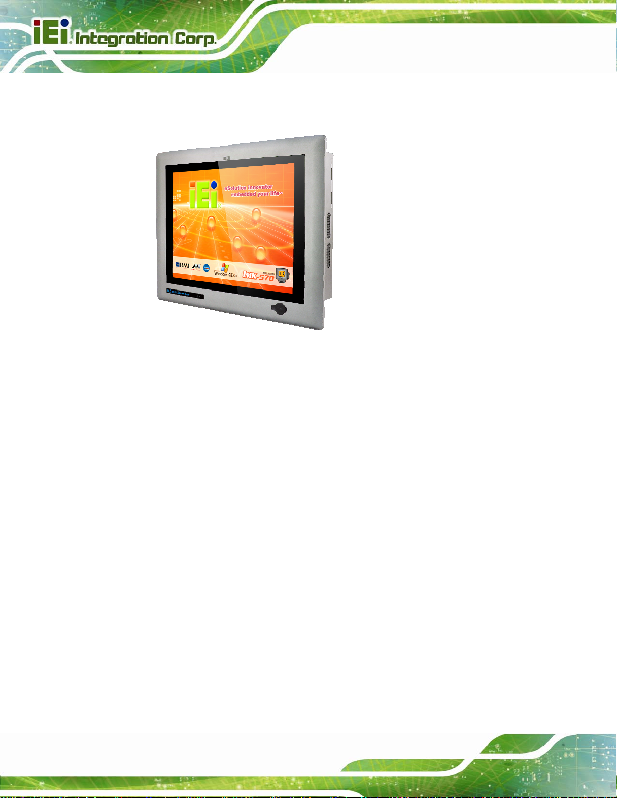
Figure 1-1: PPC-5152-D525 Panel PC
The fanless PPC-5152-D525 is Intel® Atom D525 powered flat-bezel panel PC with a
rich variety of functions and peripherals. The PPC-5152-D525 panel PC is designed for
easy and simplified integration in to various applications.
An Intel® ICH8M chipset ensures optimal memory, graphics, and peripheral I/O support.
The system comes with 1GB of preinstalled DDR3 SDRAM ensuring smooth data
throughputs with reduced bottlenecks and fast system access.
Five serial ports and six USB ports ensure simplified connectivity to a variety of external
peripheral devices. A VGA connector enables connectivity to other monitors. Wi-Fi
capabilities and the dual combo (SFP Fiber/RJ-45) gigabit LAN connectors ensure smooth
connection of the system to an external LAN.
Page 2
Page 17

PPC-5152-D525 Falt-bezel Panel PC
1.2 Model Variations
The model numbers and model variations are listed below.
Model CPU Expansion Slots
PPC-5152-D525/R/1G/2P-R11
PPC-5152-D525/R/1G/1P1E-R11
Table 1-1: Model Variations
1.3 Features
All the PPC-5152-D525 models feature the following:
15'' 400nits 1024 x 768 LCD with LED backlight
5-wire resistive type touch screen
Fanless system with 1.8GHz Intel® Atom™ D525 dual-core processor
Dual combo gigabit Ethernet ports (10/100/1000 Base-T(X) or 1000 Base
Built-in 2-megapixel webcam with AE and AWB capabilities
Flexible expansion interfaces:
SFP)
o Two PCI slots or
Intel® Atom D525
Intel® Atom D525
Two PCI slots
One PCI slot and one PCIe x1 slot
o One PCI slot and one PCIe x1 slot
Six USB ports:
o 2 x USB 2.0 (I/O panel)
o 2 x USB 3.0 (I/O panel)
o 1 x USB 2.0 (front panel)
o 1 x USB 2.0 (internal)
Five serial ports:
o 2 x RS-232 (DB-9)
o 2 x RS-422/485 (RJ-45)
o 1 x RS-232/422/485 (DB-9)
Optional Wi-Fi 802.11b/g/n connection
IP 64 compliant system
AT or ATX power mode
RoHS comlpliance
Page 3
Page 18

1.4 External Overview
The flat panel PC is a rectangular cubic structure that comprises of a screen, rear panel,
top panel, bottom panel and two side panels (left and right). An aluminum frame surrounds
the front screen. The rear panel provides screw holes for a wall-mounting bracket, and an
arm mounting interface. The bottom panel provides access to external interface
connectors.
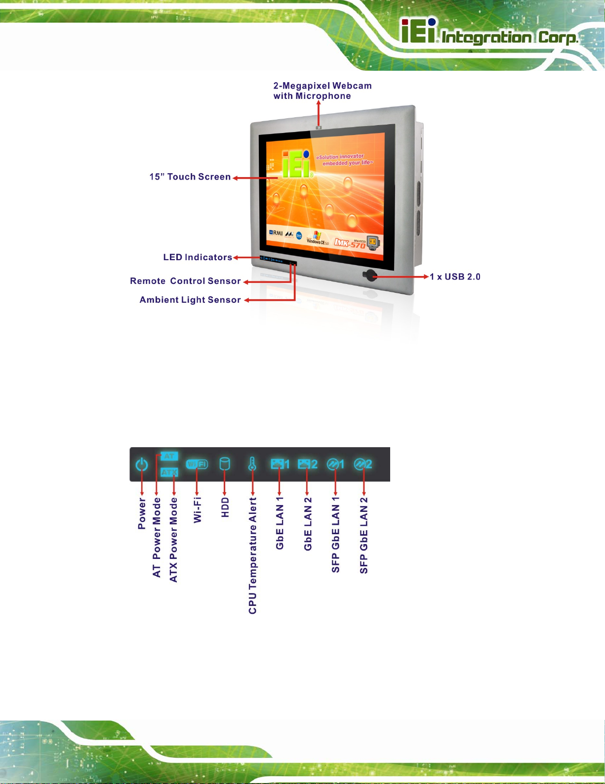
1.4.1 Front Panel
The front side of the PPC-5152-D525 is a flat panel TFT LCD screen surrounded by an
aluminum frame. At the top of the front panel features one 2-megapixel webcam that
supports auto-exposure (AE) and auto white balance (AWB). The front panel also has
following connector, LED indicators and sensors:
One USB 2.0 port
PPC-5152-D525 Falt-bezel Panel PC
LEDs
o Power LED
o AT/ATX power mode LEDs
o Wi-Fi connection LED
o HDD activity LED
o CPU temperature alert LED
o LAN connection LEDs
o SFP connection LEDs
Sensors
o Infrared remote control sensor
o Ambient light sensor
Page 4
Page 19
PPC-5152-D525 Falt-bezel Panel PC
Figure 1-2: Front View
1.4.1.1 LED Indicators
The LED indicators on the front panel of the PPC-5152-D525 are shown below.
Figure 1-3: LED Indicators
The descriptions of each LED indicator are listed below.
Page 5
Page 20
LED Indicator Description
Power Power on.
AT/ATX Power Mode Shows the power mode status. Controlled by the AT/ATX power mode
switch on the bottom panel.
Wi-Fi The Wi-Fi module is enabled or disabled. Controlled by the BIOS (see
PPC-5152-D525 Falt-bezel Panel PC
Section
HDD Shows the HDD activity.
CPU Temperature Alert Blue: the CPU temperature is normal.
Red: the CPU temperature is too high.
LAN 1 The LAN 1 port is linked.
LAN 2 The LAN 2 port is linked.
SFP 1 The SFP 1 port is linked.
SFP 2 The SFP 2 port is linked.
5.4.2).
6
Table 1-2: LED Indicators
NOTE:
If the CPU temperature alert LED shows in red, the user must lower the
environment temperature or close some running applications to cool
down the CPU.
1.4.2 Bottom Panel
The following is a list of the bottom panel peripheral device connectors on the
PPC-5152-D525.
1 x 9 V ~ 36 V DC power input terminal block
1 x 9 V ~ 36 V DC power input connector
2 x Audio jacks
1 x CAN but connector
2 x RJ-45 GbE connector
2 x SFP Fiber Gigabit LAN connectors
Page 6
Page 21
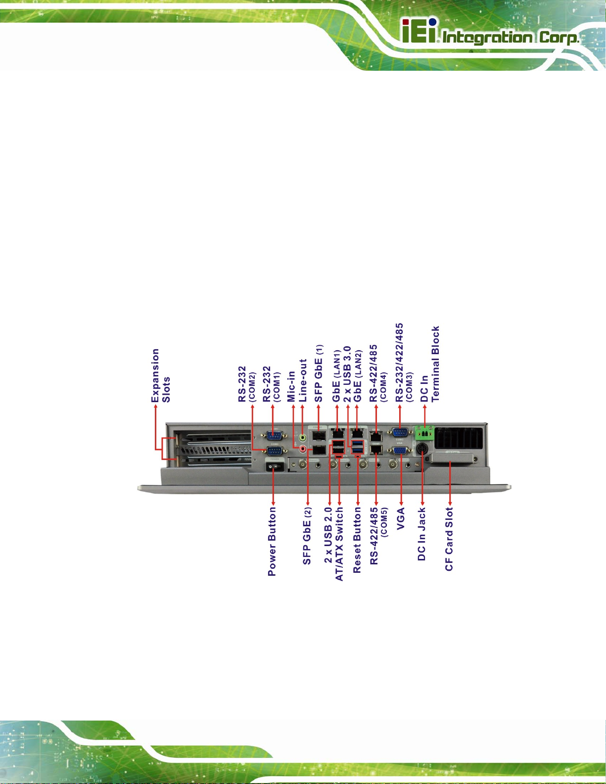
PPC-5152-D525 Falt-bezel Panel PC
2 x RS-232 serial port connector (COM1, COM2)
1 x RS-232/422/485 serial port (COM3) connector
2 x RS-422/485 COM ports by RJ-45 connectors (COM4, COM5)
2 x USB 2.0 connectors
2 x USB 3.0 connectors
1 x VGA connector
1 x CF Type II slot
2 x Expansion slots for PCI/PCIe expansion modules
The bottom panel also includes the following switches and buttons:
1 x Power switch
1 x AT/ATX power mode switch
1 x Reset button
Figure 1-4: Bottom View
Page 7
Page 22
PPC-5152-D525 Falt-bezel Panel PC
NOTE:
The PPC-5152-D525 provides two pairs of combo LANs, one is SFP
fiber and the other is GbE. For each pair of combo LAN, only one LAN
port can work at one time, and the SFP Fiber port works prior to the
RJ-45 one. When a LAN port is linked, the corresponding LED indicator
lights up. Refer to Section
61.4.1.1 for the locations of the LED
indicators.
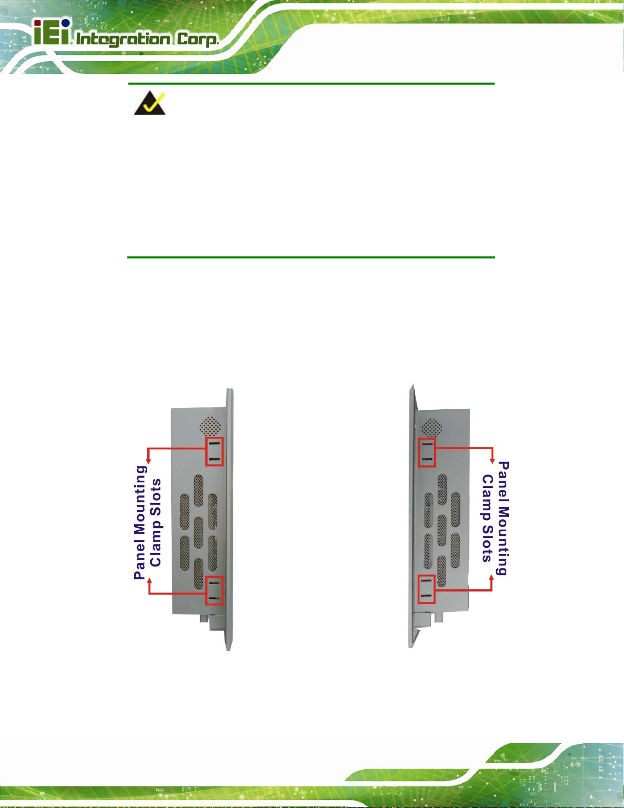
1.4.3 Side Panels
Both side panels of the flat panel PC have some vents for ventilation and slots for
installing the panel mounting clamps (
556Figure 1-5).
Page 8
Figure 1-5: Side View
Page 23
PPC-5152-D525 Falt-bezel Panel PC
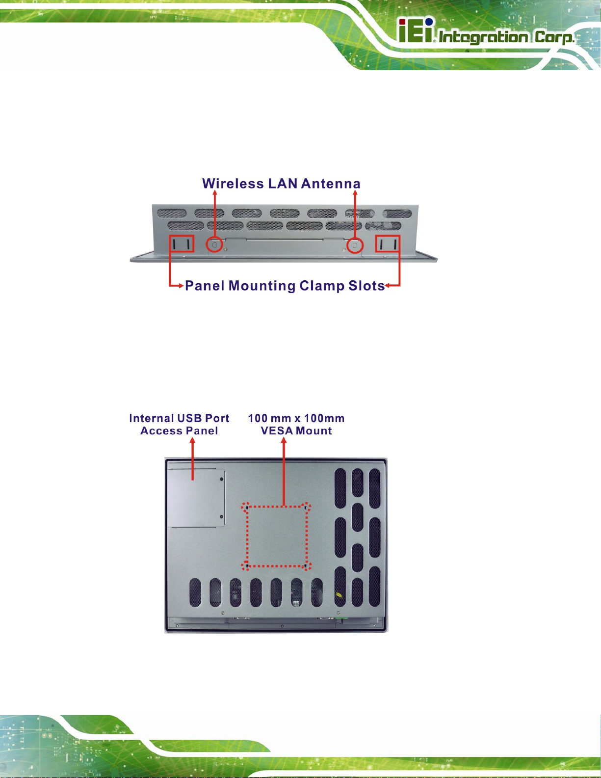
1.4.4 Top Panel
The top panel of the flat panel PC have some vents for ventilation and slots for installing
the panel mounting clamps. The model with wireless LAN module also includes two
wireless LAN antenna connectors on the top panel (
Figure 1-6: Top View
556Figure 1-5).
1.4.5 Rear Panel
The rear panel has retention screw holes that support a wall-mounting bracket. The rear
panel also provides access to the internal USB port.
Figure 1-7: Rear View
Page 9
Page 24
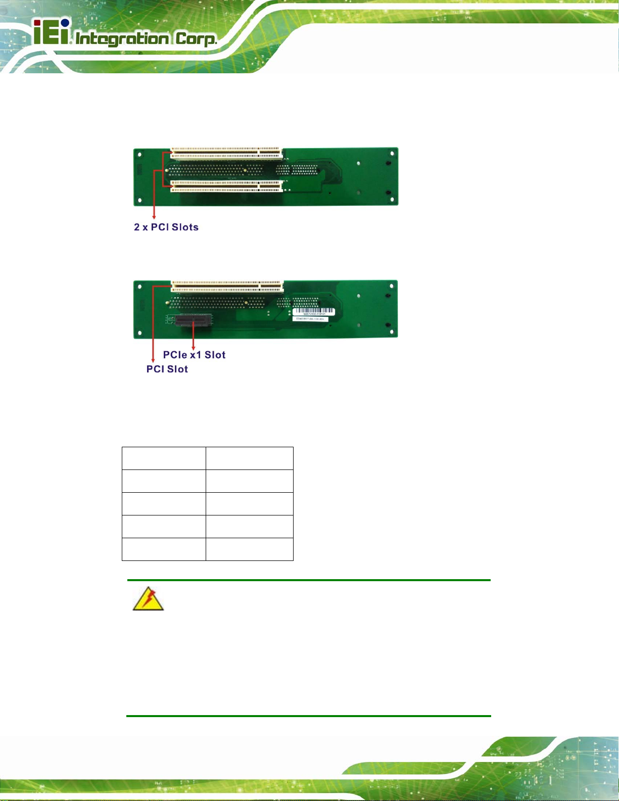
1.5 Backplane Options
The backplane options of the PPC-5152-D525 are shown below.
PPC-5152-D525 Falt-bezel Panel PC
Figure 1-8: Backplane Option 1 (HPE-2S1)
Figure 1-9: Backplane Option 2 (HPE-2S2)
The rated voltage and current of the backplane are listed below:
Rated Voltage Rated Current
+5 V 5 A
+12 V 2.4 A
-12 V 0.1 A
+3.3 V 8 A
Page 10
WARNING:
The system default power is 96 W. The maximum total power of the
backplane to support expansion cards is 35 W. The power of the
selected expansion cards can not exceed the max. power (35 W),
otherwise, the system may fail.
Page 25
PPC-5152-D525 Falt-bezel Panel PC
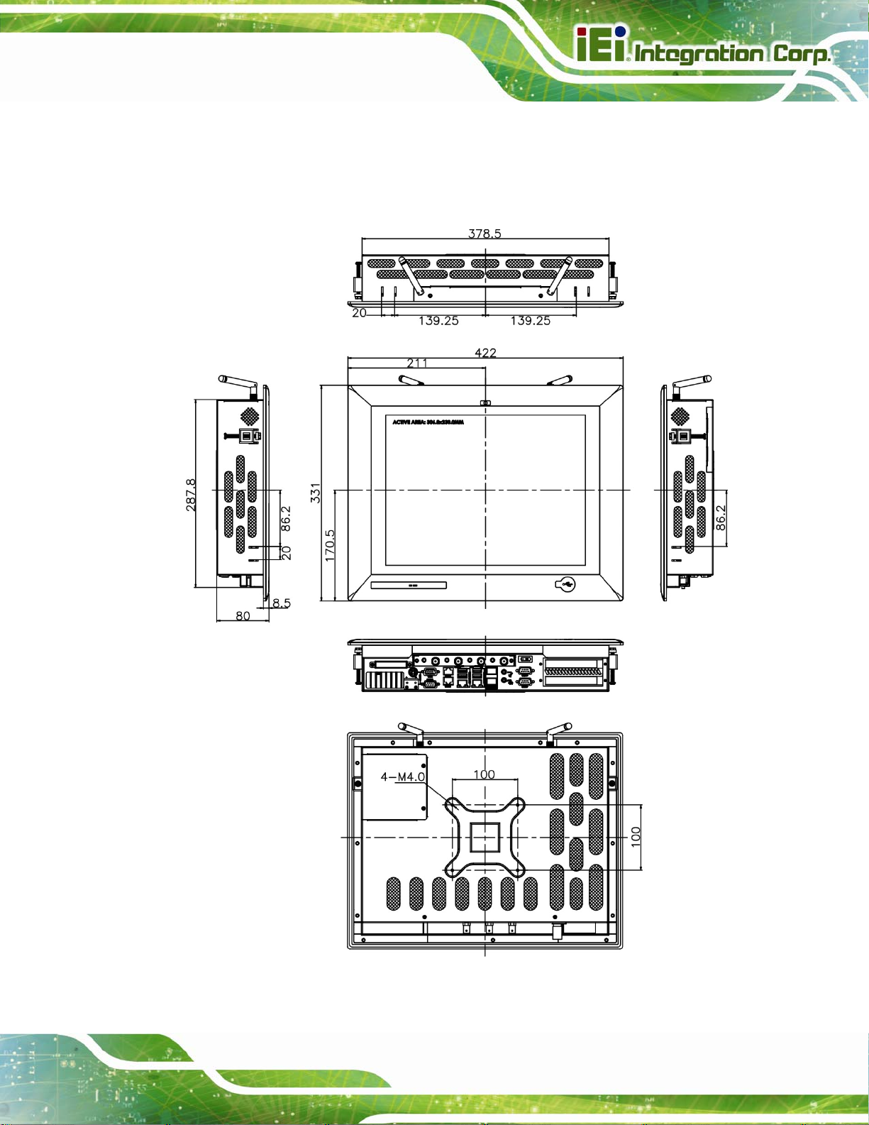
1.6 Dimensions
The dimensions of the PPC-5152-D525 are shown in 556Figure 1-10 and listed below.
Figure 1-10: PPC-5152-D525 Dimensions (mm)
Page 11
Page 26

1.7 Specifications
The technical specifications for the PPC-5152-D525 system are listed in 556Table 1-3.
PPC-5152-D525 Falt-bezel Panel PC
Specification
LCD Size
Max. Resolution
Brightness
Contrast Ratio
LCD Color
Pixel Pitch (mm)
Viewing Angle (H-V)
Backlight MTBF
SBC Model
CPU
Chipsets
PPC-5152-D525
15”
1024 x 768 (XGA)
400 cd/m
500:1
16.2 M
0.1095 (H) x 0.1095 (V)
160 (H) / 140 (V)
50,000 hours
PPCMB-5152A-D525
1.8 GHz Intel® Atom™ D525 dual-core processor
Intel® ICH8M
2
Page 12
Memory
Ethernet
Drive Bay
CompactFlash®
SSD
Watchdog Timer
Camera
Ethernet
On-board 1.0 GB DDR3 SDRAM SO-DIMM
(system max. 4 GB)
Realtek RTL8111E PCIe GbE controller supports ASF 2.0
One 2.5” SATA HDD bay
One CF Type II socket
SATA slim SSD
Software Programmable supports 1 sec. ~ 255 sec.
system reset
2-megapixel webcam supports AE and AWB
Dual Combo (SFP Fiber/RJ-45) Gigabit LAN
Page 27

PPC-5152-D525 Falt-bezel Panel PC
Wireless LAN
Audio
Expansion
Construction Material
Mounting
Front Panel Color
Dimensions (W x H x D)
Cut-out Dimensions (W x H)
Optional 802.11b/g/n wireless module
2 x Audio speakers
1 x Line-out connector
1 x Mic-in connector
Two PCI slots or
One PCI slot and one PCIe x1 slot
Aluminum (front panel)
Heavy-duty steel (chassis)
Wall, Panel, Rack, Stand, Arm (VESA 100 mm x 100 mm)
PMS 8401C
422 mm x 331 mm x 80 mm
390 mm x 290 mm
Weight (Net/Gross)
Operating Temperature
Storage Temperature
Relative Humidity
IP Level
Touch Screen
Vibration
Shock
Power Adapter
6.5kg/7.0kg
-20ºC ~ 50ºC
-30ºC ~ 80ºC
5%~90%, non-condensing
IP 64 compliant front panel
5-wire resistive type
MIL-STD-810F 514.5C-2 (with CF card or SSD)
Half-sine wave shock 3G; 11ms; 3 shocks per axis
90 W
Input: 100 VAC ~ 240 VAC @ 50 Hz / 60 Hz
Output: 19 VDC
Page 13
Page 28

PPC-5152-D525 Falt-bezel Panel PC
Power Requirement
Power Consumption
I/O Ports and Switches
DC input:
Terminal block: 9 V ~ 36 V
DC jack: 9 V ~ 36 V
50 W (without add-on card)
1 x 9~36 V DC In terminal block
1 x 9~36 V DC In jack
Five serial ports :
2 x DB-9 RS-232 ports
1 x DB-9 RS-232/422/485 port
2 x RJ-45 RS-422/485 ports
Six USB ports:
2 x USB 2.0 (I/O panel)
2 x Combo (SFP Fiber/RJ-45) Gigabit LAN
2 x Audio jacks (Line-out, Mic-in)
1 x VGA connector
1 x AT/ATX power mode switch
1 x Power switch
1 x Reset button
Optional 4-channel video/audio capture connectors
Table 1-3: System Specifications
2 x USB 3.0 (I/O panel)
1 x USB 2.0 (front panel)
1 x USB 2.0 (internal)
Page 14
Page 29

PPC-5152-D525 Falt-bezel Panel PC
Chapter
2
2 Unpacking
Page 15
Page 30

2.1 Unpacking
To unpack the flat panel PC, follow the steps below:
WARNING!
The front side LCD screen has a protective plastic cover stuck to the
screen. Only remove the plastic cover after the panel PC has been properly
installed. This ensures the screen is protected during the installation
process.
Step 1: Use box cutters, a knife or a sharp pair of scissors that seals the top side of the
external (second) box.
PPC-5152-D525 Falt-bezel Panel PC
Step 2: Open the external (second) box.
Step 3: Use box cutters, a knife or a sharp pair of scissors that seals the top side of the
internal (first) box.
Step 4: Lift the monitor out of the boxes.
Step 5: Remove both polystyrene ends, one from each side.
Step 6: Pull the plastic cover off the panel PC.
Step 7: Make sure all the components listed in the packing list are present. Step 0:
Page 16
Page 31

PPC-5152-D525 Falt-bezel Panel PC
2.2 Packing List
The PPC-5152-D525 panel PC is shipped with the following components:
Quantity Item Image
1 PPC-5152-D525 panel PC
1 Power adapter
(P/N: 63040-010090-020-RS)
1 Power cord
(P/N: 32702-000401-100-RS)
1 Power transfer cord
(P/N: 32000-089400-RS)
2 RJ-45 to DB-9 COM port cable
(P/N: 32005-000700-100-RS)
1 Remote control
(P/N: 7Z000-8T00320ICP05G-RS)
1 Pluggable DC-in terminal block
(P/N: 33101-000897-RS)
Page 17
Page 32

4 HDD installation screws (M3*4)
PPC-5152-D525 Falt-bezel Panel PC
(P/N: 44043-030051-RS)
4 VESA mount screws (M4*6)
(P/N: 44033-040062-RS)
4 Backup chassis screws (M3*4)
(P/N: 44013-030041-RS)
4 Backup capture card screws (M3*6)
(P/N: 44003-030062-RS)
6 Panel mounting clamps
(P/N: 19Z00-000024-RS)
1 Touch pen
(P/N: 43125-0002C0-00-RS)
1 User manual CD and driver CD
(P/N: IEI-7B000-000732-RS)
1 One Key Recover CD
(P/N: IEI-7B000-000724-RS)
If any of these items are missing or damaged, contact the distributor or sales
representative immediately.
Page 18
Page 33

PPC-5152-D525 Falt-bezel Panel PC
Chapter
3
3 Installation
Page 19
Page 34

3.1 Anti-static Precautions
WARNING:
Failure to take ESD precautions during the maintenance of the EP
series may result in permanent damage to the EP series and severe
injury to the user.
Electrostatic discharge (ESD) can cause serious damage to electronic components,
including the PPC-5152-D525. Dry climates are especially susceptible to ESD. It is
therefore critical that whenever the PPC-5152-D525 is accessed internally, or any other
electrical component is handled, the following anti-static precautions are strictly adhered
to.
PPC-5152-D525 Falt-bezel Panel PC
Wear an anti-static wristband: - Wearing a simple anti-static wristband can
help to prevent ESD from damaging the board.
Self-grounding: - Before handling the board touch any grounded conducting
material. During the time the board is handled, frequently touch any
conducting materials that are connected to the ground.
Use an anti-static pad: - When configuring the PPC-5152-D525, place it on
an antic-static pad. This reduces the possibility of ESD damaging the
PPC-5152-D525.
Only handle the edges of the PCB: - When handling the PCB, hold the PCB
by the edges.
3.2 Installation Precautions
When installing the panel PC, please follow the precautions listed below:
Power turned off: When installing the panel PC, make sure the power is off.
Failing to turn off the power may cause severe injury to the body and/or
damage to the system.
Page 20
Certified Engineers: Only certified engineers should install and modify
onboard functionalities.
Anti-static Discharge : If a user open the rear panel of the panel PC, to
Page 35

PPC-5152-D525 Falt-bezel Panel PC
configure the jumpers or plug in added peripheral devices, ground themselves
first and wear and anti-static wristband.
3.3 Preinstalled Components
The following components are all preinstalled.
Motherboard
TFT LCD screen
DDR3 memory module
Resistive type touch screen
Stereo speakers
Webcam
PCI riser card
Preinstalled OEM customizations may include the following.
Different DDR3 memory module
Wireless module
Video/audio capture card
3.4 CompactFlash® Installation
To install the CompactFlash® card, please follow the steps below:
Step 1: Undo the CompactFlash® slot cover screw and remove the CompactFlash® slot
cover.
Figure 3-1: CompactFlash® Cover Plate
Page 21
Page 36

Step 2: Insert the CompactFlash® card into the slot.
Figure 3-2: CompactFlash® Slot
Step 3: Fasten the CompactFlash® cover plate.Step 0:
PPC-5152-D525 Falt-bezel Panel PC
3.5 USB Devices Installation (Internal)
The PPC-5152-D525 has one internal USB 2.0 port inside the chassis. This USB port is
reserved for the USB encryption card, which provides software developers an intelligent
software protection tool. The software and data protection can prevent intelligent property
from being used illicitly.
To access the internal USB 2.0 port, follow the instructions below.
Step 1: Remove the internal USB port access panel by removing the two retention
screws.
Page 22
Page 37

PPC-5152-D525 Falt-bezel Panel PC
Figure 3-3: Remove the Internal USB Port Access Panel
Step 2: Locate the internal USB port. See
556Figure 3-4.
Figure 3-4: Internal USB Port Location
Step 3: Install the USB dongle. Correctly align the USB dongle with the connector and
insert the USB dongle into the connector.
Step 4: Reinstall the internal USB port access panel. Step 0:
Page 23
Page 38

PPC-5152-D525 Falt-bezel Panel PC
3.6 SFP Optical Module Installation (Optional)
The following SFP optical module can be purchased separately.
Figure 3-5: SFP Optical Module
To install the SFP optical module, please follow the steps below:
Step 1: Locate the SFP fiber connectors. The locations of the connectors are shown in
6Figure 1-4.
Step 2: Align the SFP module with one of the SFP fiber connectors on the
PPC-5152-D525 (
Step 3: Once aligned, slide the SFP module into place (
6Figure 3-6).
6Figure 3-6).
Figure 3-6: SFP Module Installation
Page 24
Page 39

PPC-5152-D525 Falt-bezel Panel PC
NOTE:
The pin locations of the SFP connector 2 are opposite to the SFP
connector 1. Please rotate the SFP module to a proper position to
install the SFP module into the SFP connector 2.
3.7 HDD Installation
The PPC-5152-D525 has one internal HDD bay. To install the HDD, follow the instructions
below.
Step 1: Remove a total of ten retention screws from the back cover, eight on the rear of
the frame and two on the rear panel (
Figure 3-7: Rear Panel Retention Screws
6Figure 3-7).
Step 2: Remove the four HDD bracket retention screws and unplug the SATA cable and
the SATA power cable from the motherboard. See
6Figure 3-8.
Page 25
Page 40

PPC-5152-D525 Falt-bezel Panel PC
Figure 3-8: HDD Bracket Retention Screws
Step 3: Lift the HDD bracket out of the PPC-5152-D525.
Step 4: Remove the SATA connector from the bracket by removing the two retention
screws on the bottom of the bracket.
Step 5: Connect the HDD to the SATA connector first, then place the HDD onto the
bracket. Secure the SATA connector with the HDD bracket by two previously
removed screws.
Step 6: Secure the HDD with the HDD bracket by four retention screws (
6Figure 3-9).
Page 26
Figure 3-9: HDD Installation
Page 41

PPC-5152-D525 Falt-bezel Panel PC
Step 7: Secure the HDD bracket with the PPC-5152-D525 by the four retention screws
that were previously removed (
6Figure 3-10).
Figure 3-10: HDD Bracket Installation
Step 8: Connect the SATA cable and the SATA power cable to the corresponding
connectors on the motherboard.
Step 9: Reinstall the rear panel to the PPC-5152-D525.
Page 27
Page 42

PPC-5152-D525 Falt-bezel Panel PC
3.8 PCI Expansion Card Installation
CAUTION:
The maximum dimensions of the expansion card should be 200 mm in
length, 100 mm in width and 20 mm in height. The width of the I/O panel
should be no more than 73.8 mm. The diagram below shows the
dimensions of the expansion slot on the bottom panel of the
PPC-5152-D525.
To install a PCI expansion card, please do the following.
Step 1: Remove the rear cover. See Section
Step 2: Remove the expansion slot cover. The expansion slot cover is secured to the
system with a single retention screw. Remove the screw.
63.7 Step 1.
Page 28
Page 43

PPC-5152-D525 Falt-bezel Panel PC
Figure 3-11: Expansion Slot Retention Screw
Step 3: Insert the expansion card. Align the PCI expansion card edge connector with the
PCI expansion slot on the PCI riser card. Gently insert the PCI card into the PCI
expansion slot.
Step 4: Secure the expansion card. Once the PCI card is correctly installed in the
system, reinsert the previously removed retention screw to secure the card to
the I/O interface panel.Step 0:
Figure 3-12: Install PCI Card
Page 29
Page 44

PPC-5152-D525 Falt-bezel Panel PC
3.9 PCIe Expansion Card Installation (Optional)
CAUTION:
The maximum dimensions of the expansion card should be 200 mm in
length, 100 mm in width and 20 mm in height. The width of the I/O panel
should be no more than 73.8 mm. The diagram below shows the
dimensions of the expansion slot on the bottom panel of the
PPC-5152-D525.
To install a PCIe expansion card, please do the following.
Step 1: Remove the rear cover. See Section
Step 2: Remove the expansion slot cover. The expansion slot cover is secured to the
system with a single retention screw. Remove the screw.
63.7 Step 1.
Page 30
Page 45

PPC-5152-D525 Falt-bezel Panel PC
Figure 3-13: Expansion Slot Retention Screw
Step 3: Insert the expansion card. Align the PCIe expansion card edge connector with
the PCIe expansion slot on the PCIe riser card. Gently insert the PCIe card into
the PCIe expansion slot.
Step 4: Secure the expansion card. Once the PCIe card is correctly installed in the
system, reinsert the previously removed retention screw to secure the card to
the I/O interface panel.Step 0:
Figure 3-14: Install PCIe Card
Page 31
Page 46

3.10 Mounting the System
WARNING:
When mounting the flat panel PC onto an arm or onto the wall, it is
better to have more than one person to help with the installation to
make sure the flat panel PC does not fall down and get damaged.
The following installation options are available:
Arm mounting
Panel mounting
Rack/Cabinet mounting
Stand mounting
PPC-5152-D525 Falt-bezel Panel PC
The mounting methods are described below.
Wall mounting
3.10.1 Arm Mounting
The PPC-5152-D525 can be installed on any arm that supports the standard VESA
mounting interface. An example arm is shown below.
Figure 3-15: VESA Compliant Arm
To install the PPC-5152-D525 on the arm, follow the directions below.
Page 32
Page 47

PPC-5152-D525 Falt-bezel Panel PC
NOTE:
Make sure the arm supports standard VESA mounting. The
PPC-5152-D525 uses a VESA mounting to attach to the arm.
Step 1: The arm is purchased separately. Follow the instructions in the arm's user
manual to securely attach the arm to the wall.
Step 2: Once the mounting arm has been firmly attached to the surface, lift the panel PC
onto the interface pad of the mounting arm.
Step 3: Align the retention screw holes on the mounting arm interface with those in the
panel PC. The arm mount retention screw holes are shown in
Figure 3-16: Arm Mounting Retention Screw Holes
Step 4: Secure the flat panel PC to the interface pad by inserting four retention screws
Figure 3-16.
through the bottom of the mounting arm interface pad and into the flat panel PC.
Step 0:
Page 33
Page 48

3.10.2 Panel Mounting
To mount the PPC-5152-D525 flat panel PC into a panel, please follow the steps below.
Step 1: Select the position in the panel to mount the panel PC.
Step 2: Cut out a section from the panel that corresponds to the dimensions of the flat
panel PC chassis. The panel section that is cut out must be smaller than the size
of the aluminum frame that surrounds the TFT LCD panel but just large enough
PPC-5152-D525 Falt-bezel Panel PC
for the chassis to fit through. Refer to
Figure 3-17: Suggested Panel Cut Out Size for PPC-5152-D525 (Unit: mm)
556Figure 3-17 for the suggested cut out size.
Page 34
Step 3: Slide the flat panel computer through the previously cut hole. The chassis at the
rear of the flat panel should slide easily through the hole. Only stop sliding the
panel through the hole when the back of the front aluminum frame is flush
against the panel.
Step 4: Insert the panel mounting clamps into the pre-formed holes along the edges of
the chassis, behind the frame. There are a total of 6 panel mounting clamps for
PPC-5152-D525.
Page 49

PPC-5152-D525 Falt-bezel Panel PC
Figure 3-18: Panel Mounting Clamp Slots (Side View)
Step 5: Tighten the screws that pass through the panel mounting clamps until the plastic
caps at the front of all the screws are firmly secured to the panel (
556Figure 3-19).
Page 35
Page 50

PPC-5152-D525 Falt-bezel Panel PC
Figure 3-19: Tighten the Panel Mounting Clamp Screws
3.10.3 Rack/Cabinet Mounting
The PPC-5152-D525 panel PC can be installed into a rack or cabinet. The installation
procedures are similar to the panel mounting installation. To do this, please follow the
steps below:
NOTE:
When purchasing the cabinet/rack installation bracket, make sure it is
compatible with both the PPC-5152-D525 flat panel PC and the
rack/cabinet into which the PPC-5152-D525 is installed.
Step 1: Slide the rear of the PPC-5152-D525 panel PC through the rack/cabinet bracket
Page 36
until the aluminum frame is flush against the front of the bracket (
Figure 3-20).
Page 51

PPC-5152-D525 Falt-bezel Panel PC
Figure 3-20: The Rack/Cabinet Bracket
Step 2: Insert the rack mounting clamps into the pre-formed holes along the edges of
the panel PC, behind the ABS/PC plastic frame.
Step 3: Tighten the screws that pass through the rack mounting clamps until the plastic
caps at the front of all the screws are firmly secured to the bracket
Figure 3-21).
(
Figure 3-21: Secure the Rack/Cabinet Bracket
Page 37
Page 52

Step 4: Slide the panel PC with the attached rack/cabinet bracket into a rack or cabinet
Figure 3-22).
(
PPC-5152-D525 Falt-bezel Panel PC
Figure 3-22: Install into a Rack/Cabinet
Step 5: Once the panel PC with the attached rack/cabinet bracket has been properly
inserted into the rack or cabinet, secure the front of the rack/cabinet bracket to
the front of the rack or cabinet (
Figure 3-22).
3.10.4 Stand Mounting
The PPC-5152-D525 can be installed on any stand that supports the standard VESA
mounting interface. An example stand is shown below.
Figure 3-23: VESA Compliant Stand
Page 38
To install the PPC-5152-D525 on the stand, follow the directions below.
Page 53

PPC-5152-D525 Falt-bezel Panel PC
Step 1: Locate the screw holes on the rear of the PPC-5152-D525. This is where the
stand bracket will be attached. The stand mount retention screw holes are
shown in
Figure 3-24: Stand Mounting Retention Screw Holes
Step 2: Align the bracket with the screw holes.
Step 3: Insert the retention screws into the screw holes to secure the bracket to the
Figure 3-24.
PPC-5152-D525. Step 0:
3.10.5 Wall Mounting
To mount the panel PC onto the wall, please follow the steps below.
Step 1: Select the location on the wall for the wall-mounting bracket.
Step 2: Carefully mark the locations of the four brackets screw holes on the wall.
Step 3: Drill four pilot holes at the marked locations on the wall for the bracket retention
screws.
Step 4: Align the wall-mounting bracket screw holes with the pilot holes.
Step 5: Secure the mounting-bracket to the wall by inserting the retention screws into
the four pilot holes and tightening them (
Figure 3-25).
Page 39
Page 54

Figure 3-25: Wall-mounting Bracket
Step 6: Insert the four monitor mounting screws provided in the wall mounting kit into the
PPC-5152-D525 Falt-bezel Panel PC
four screw holes on the real panel of the flat panel PC and tighten until the screw
shank is secured against the rear panel (
Step 7: Align the mounting screws on the monitor rear panel with the mounting holes on
the bracket.
Step 8: Carefully insert the screws through the holes and gently pull the monitor
downwards until the monitor rests securely in the slotted holes (
Ensure that all four of the mounting screws fit snuggly into their respective
slotted holes.
Figure 3-26).
Figure 3-26).
Page 40
Page 55

PPC-5152-D525 Falt-bezel Panel PC
Figure 3-26: Chassis Support Screws
NOTE:
In the diagram below the bracket is already installed on the wall.
Step 9: Secure the panel PC by fastening the retention screw of the wall-mounting
bracket. (
Figure 3-27). Step 9:
Page 41
Page 56

PPC-5152-D525 Falt-bezel Panel PC
Figure 3-27: Secure the Panel PC
3.11 Bottom Panel Connectors
The bottom panel of the PPC-5152-D525 contains I/O connectors, switches and a CF card
slot. Detailed descriptions of the connectors can be found in the subsections below.
3.11.1 Audio Connectors
The audio jacks connect to external audio devices.
Microphone (Pink): Connects a microphone.
Line Out port (Green): Connects to a headphone or a speaker. With
multi-channel configurations, this port can also connect to front speakers.
Page 42
Page 57

PPC-5152-D525 Falt-bezel Panel PC
3.11.2 LAN Connector
The LAN connector allows connection to an external network. The pinouts of the RJ-45
LAN connector is shown below.
Pin Description Pin Description
1 MDI0+ 2 MDI03 MDI1+ 4 MDI15 MDI2+ 6 MDI27 MDI3+ 8 MDI3-
Table 3-1: LAN Pinouts
Figure 3-28: RJ-45 Ethernet Connector
The RJ-45 Ethernet connector has two status LEDs, one green and one yellow. See
6Figure 3-28.
LED Description LED Description
A on: linked
blinking: data is being sent/received
Table 3-2: RJ-45 Ethernet Connector LEDs
B off: 10 Mb/s
green: 100 Mb/s
orange: 1000 Mb/s
To connect the PPC-5152-D525 to a network through the RJ-45 LAN connector, follow the
steps below.
Step 1: Locate the RJ-45 connector. The location of the RJ-45 connectors is shown in
6Figure 1-4.
Page 43
Page 58

PPC-5152-D525 Falt-bezel Panel PC
Step 2: Align the connectors. Align the RJ-45 connector on the LAN cable with one of
the RJ-45 connectors on the PPC-5152-D525. See
6Figure 3-29.
Figure 3-29: LAN Connection
Step 3: Insert the LAN cable RJ-45 connector. Once aligned, gently insert the LAN cable
RJ-45 connector into the on-board RJ-45 connector.
3.11.3 Power Input, 2-pin Terminal Block
CN Label: DC IN
CN Type:
CN Location:
CN Pinouts:
3-pin terminal block
6Figure 1-4
See
6Figure 3-30
See
Connect the leads of a 9 V~36 V DC power supply into the terminal block. Make sure that
the power and ground wires are attached to the correct sockets of the connector.
Page 44
Page 59

PPC-5152-D525 Falt-bezel Panel PC
Figure 3-30: 2-pin Terminal Block Pinouts
The PPC-5152-D525 comes with a pluggable DC-in terminal block. To install the terminal
block into the power input connector, follow the steps below.
Step 1: Locate the 2-pin power input connector. The location of the power input
connector is shown in
6Figure 1-4.
Step 2: Insert the terminal block into the 2-pin power input connector on the external
peripheral interface.
Step 3: Secure the terminal block to the external interface by tightening the two slot
head screws. See
6Figure 3-34.
Figure 3-31: Power Input Terminal Block Installation
3.11.4 Power Input, DIN Connector
CN Label: DC IN
CN Type:
CN Location:
4-pin DIN connector
6Figure 1-4
See
Page 45
Page 60

The power connector connects to the 9 V ~ 36 V DC power adapter.
3.11.5 RS-232 Serial Port (COM1, COM2)
CN Label: COM1, COM2
PPC-5152-D525 Falt-bezel Panel PC
CN Type:
CN Location:
CN Pinouts:
DB-9 connector
6Figure 1-4
See
6Table 3-4 and 6Figure 3-33
See
An RS-232 device can be connected to the RS-232 serial port on the bottom panel. The
pinouts of the RS-232 serial port is shown below.
Figure 3-32: RS-232 Serial Port
Pin Description
1 DCD
Page 46
2 DSR
3 RX
4 RTS
5 TX
6 CTS
7 DTR
8 RI
9 GND
Table 3-3: RS-232 Serial Port Pinouts
Page 61

PPC-5152-D525 Falt-bezel Panel PC
3.11.6 RS-232/422/485 Serial Port (COM3)
CN Label: COM3
CN Type:
CN Location:
CN Pinouts:
DB-9 connector
6Figure 1-4
See
6Table 3-4 and 6Figure 3-33
See
An RS-232/422/485 device can be connected to the RS-232/422/485 serial port on the
bottom panel. The pinouts of the RS-232/422/485 serial port is shown below.
Figure 3-33: RS-232/422/485 Serial Port
Pin RS-232 RS-422 RS-485
1 DCD RX+
2 RXD RX-
3 TXD TX+ DATA+
4 DTR TX- DATA5 GND
6 DSR
7 RTS
8 CTS
9 RI
Table 3-4: RS-232/422/485 Serial Port Pinouts
To install the RS-232/422/485 devices, follow the steps below.
Step 1: Locate the DB-9 connector. The locations of the DB-9 connectors are shown in
6Figure 1-4.
Page 47
Page 62

PPC-5152-D525 Falt-bezel Panel PC
Step 2: Insert the serial connector. Insert the DB-9 connector of a serial device into the
DB-9 connector on the external peripheral interface. See
6Figure 3-34.
Figure 3-34: Serial Device Connector
Step 3: Secure the connector. Secure the serial device connector to the external
interface by tightening the two retention screws on either side of the connector.
3.11.6.1 COM3 Mode Select Switch
Jumper Label: U61
Jumper Type:
Jumper Settings:
Jumper Location:
10-pin DIP switch
56Table 3-5
See
56Figure 3-35
See
The COM3 RS-232/422/485 Serial Port Select jumper sets the communication protocol
used by the second serial communications port (COM3) as RS-232, RS-422 or RS-485.
The COM3 RS-232/422/485 Serial Port Select settings are shown in
COM3 Mode Settings
RS-232 (Default) OFF: 1, 2, 3, 4, 5
ON: 6, 7, 8, 9, 10
RS-422/485 OFF: 6, 7, 8, 9, 10
ON: 1, 2, 3, 4, 5
56Table 3-5.
Table 3-5: COM3 RS-232/422/485 Serial Port Select Settings
Page 48
Page 63

PPC-5152-D525 Falt-bezel Panel PC
The COM3 RS-232/422/485 Serial Port Select jumper location is shown in 56Figure 3-35.
Figure 3-35: COM3 RS-232/422/485 Serial Port Select Switch Location
3.11.7 RJ-45 RS-422/485 Serial Port (COM4, COM5)
CN Label: COM4, COM5
CN Type:
CN Location:
CN Pinouts:
RJ-45
6Figure 1-4
See
6Table 3-6 and 6Figure 3-36
See
An RS-422/485 serial port device can be connected to the RJ-45 RS-422/485 serial port
on the bottom panel. The pinouts of the RJ-45 RS-422/485 serial port is shown below.
Figure 3-36: RJ-45 RS-422/485 Serial Port
Pin Description Pin Description
1 N/A 5 N/A
Page 49
Page 64

Pin Description Pin Description
2 TXD485# 6 RXD485#
3. N/A 7 N/A
4. TXD485+ 8 RXD485+
PPC-5152-D525 Falt-bezel Panel PC
Table 3-6: RJ-45 RS-422/485 Serial Port Pinouts
To install the RS-422/485 devices, follow the steps below.
Step 1: Locate the RJ-45 RS-422/485 connector. The location of the RJ-45 RS-422/485
connector is shown in
6Figure 1-4.
Step 2: Insert the RJ-45 connector. Insert the RJ-45 connector on the RJ-45 to DB-9
COM port cable to the RJ-45 RS-422/485 connector on the PPC-5152-D525.
6Figure 3-37.
See
Figure 3-37: RJ-45 RS-422/485 Serial Device Connection
Step 3: Insert the serial connector. Insert the DB-9 connector of a serial device into the
Page 50
DB-9 connector on the RJ-45 to DB-9 COM port cable.
Step 4: Secure the connector. Secure the serial device connector to the external
interface by tightening the two retention screws on either side of the connector.
Step 5: The DB-9 connector pinouts are listed below.
Page 65

PPC-5152-D525 Falt-bezel Panel PC
Figure 3-38: RS-422/485 Serial Port (DB-9)
Pin RS-422 RS-485
1 RX+ -2 RX- -3 TX+ DATA+
4 TX- DATA5 -- -6 -- -7 -- -8 -- -9 -- --
Table 3-7: RS-422/485 Serial Port Pinouts
3.11.8 SFP Fiber Connectors
The PPC-5152-D525 has two SFP fiber connectors. The locations of the connectors are
shown in
6Figure 1-4. To install an SFP module, refer to Section 63.6.
3.11.9 USB 2.0 Connectors
CN Label: USB2.0
CN Type:
CN Location:
CN Pinouts:
USB 2.0 port
See
See
The USB 2.0 ports are for attaching USB 2.0 peripheral devices to the system. The
pinouts of the USB 2.0 port is shown below.
6Figure 1-4
6Table 3-8
Page 51
Page 66

Pin Description Pin Description
1 VCC 5 VCC
2 DATA- 6 DATA3 DATA+ 7 DATA+
4 GROUND 8 GROUND
Table 3-8: USB 2.0 Port Pinouts
3.11.10 USB 3.0 Connectors
CN Label: USB3.0
PPC-5152-D525 Falt-bezel Panel PC
CN Type:
CN Location:
CN Pinouts:
USB 3.0 port
6Figure 1-4
See
6Table 3-8
See
The USB 3.0 ports are for attaching USB 3.0 peripheral devices to the system. To be able
to use the USB 3.0 ports, please make sure the USB 3.0 function is enabled in BIOS (see
Section
65.3.4).
The pinouts of the USB 3.0 port is shown below.
Pin Description Pin Description
1 USB_3P0_VCC1 10 USB_3P0_VCC2
2 DATA1- 11 DATA23 DATA1+ 12 DATA2+
4 GROUND 13 GROUND
5 RX1N 14 RX2N
6 RX1P 15 RX2P
Page 52
7 GROUND 16 GROUND
8 TX1N 17 TX2N
9 TX1P 18 TX2P
Table 3-9: USB 3.0 Port Pinouts
To install a USB device, follow the steps below.
Page 67

PPC-5152-D525 Falt-bezel Panel PC
Step 1: Locate the USB connectors. The locations of the USB connectors are shown in
6Figure 1-4.
Step 2: Align the connectors. Align the USB device connector with one of the connectors.
6Figure 3-39.
See
Figure 3-39: USB Device Connection
Step 3: Insert the device connector. Once aligned, gently insert the USB device
connector into the on-board connector.
3.11.11 VGA Connector
CN Label: VGA
CN Type:
CN Location:
CN Pinouts:
The VGA connector connects to a monitor that accepts VGA video input. The pinouts of
the VGA connector is shown below.
15-pin Female
6Figure 1-4
See
6Figure 3-40 and 6Table 3-10
See
Page 53
Page 68

PPC-5152-D525 Falt-bezel Panel PC
Figure 3-40: VGA Connector
Pin Description Pin Description
1 RED 2 GREEN
3 BLUE 4 NC
5 GND 6 GND
7 GND 8 GND
9 CRT_VCC 10 GND
11 NC 12 5VDDC DAT
13 HSYNC 14 VSYNC
15 5VDDCCLK
Table 3-10: VGA Connector Pinouts
To connect the PPC-5152-D525 to a second display, follow the steps below,
Step 1: Locate the female DB-15 connector. The location of the female DB-15 connector
is shown in
6Figure 1-4.
Page 54
Step 2: Align the VGA connector. Align the male DB-15 connector on the VGA screen
cable with the female DB-15 connector on the external peripheral interface.
Step 3: Insert the VGA connector. Once the connectors are properly aligned with the
insert the male connector from the VGA screen into the female connector on the
PPC-5152-D525. See
6Figure 3-41.
Page 69

PPC-5152-D525 Falt-bezel Panel PC
Figure 3-41: VGA Connector
3.12 Power-up the System
WARNING:
Make sure a power supply with the correct input voltage is being fed into
the system. Incorrect voltages applied to the system may cause damage to
the internal electronic components and may also cause injury to the user.
3.12.1 AT/ATX Power Mode Selection
The PPC-5152-D525 supports both AT and ATX power modes. The setting can be made
through the AT/ATX power mode switch on the bottom panel as shown below.
Figure 3-42: AT/ATX Power Mode Switch
Page 55
Page 70

PPC-5152-D525 Falt-bezel Panel PC
3.12.2 Powering On/Off in ATX Power Mode
Power on the system: press the power button for 3 seconds
Power off the system: press the power button for 6 seconds
Figure 3-43: Power Button
3.13 Remote Control
The PPC-5152-D525 comes with a remote control for easy configuration. 66Figure 3-44
shows the remote control and its function keys.
Figure 3-44: Remote Control
System On/Off: Press this button to turn the PPC-5152-D525 on or off.
LCD On/Off. Press this button to turn the LCD monitor on or off.
Auto-Dimming. Press this button to turn the auto-dimming function on or off.
Page 56
Brightness. Use these control buttons to adjust the brightness of the LCD
screen.
Volume. Press these buttons to adjust the audio volume level.
Page 71

PPC-5152-D525 Falt-bezel Panel PC
4 System Maintenance
Chapter
4
Page 57
Page 72

PPC-5152-D525 Falt-bezel Panel PC
4.1 System Maintenance Introduction
If the components of the PPC-5152-D525 fail they must be replaced. Components that
can be replaced include:
SO-DIMM module
WLAN Module
Please contact the system reseller or vendor to purchase the replacement parts. Back
cover removal instructions for the PPC-5152-D525 are described below.
4.2 Anti-static Precautions
WARNING:
Failure to take ESD precautions during the maintenance of the
PPC-5152-D525 may result in permanent damage to the
PPC-5152-D525 and severe injury to the user.
Electrostatic discharge (ESD) can cause serious damage to electronic components,
including the PPC-5152-D525. Dry climates are especially susceptible to ESD. It is
therefore critical that whenever the PPC-5152-D525 is accessed internally, or any other
electrical component is handled, the following anti-static precautions are strictly adhered
to.
Wear an anti-static wristband: - Wearing a simple anti-static wristband can
help to prevent ESD from damaging the board.
Self-grounding: - Before handling the board touch any grounded conducting
material. During the time the board is handled, frequently touch any
conducting materials that are connected to the ground.
Use an anti-static pad: - When configuring the PPC-5152-D525, place it on
Page 58
an antic-static pad. This reduces the possibility of ESD damaging the
PPC-5152-D525.
Only handle the edges of the PCB: - When handling the PCB, hold the PCB
by the edges.
Page 73

PPC-5152-D525 Falt-bezel Panel PC
4.3 Turn off the Power
WARNING:
Failing to turn off the system before opening it can cause permanent
damage to the system and serious or fatal injury to the user.
Before any maintenance procedures are carried out on the system, make sure the system
is turned off.
To power off the system, follow the steps below:
Step 1: Locate the power switch. See
Step 2: Hold down the power switch for six seconds to power off the system. Step 0:
4.4 Opening the System
To access the PPC-5152-D525 internally the back cover must be removed. To remove the
back cover, please follow the steps below.
Step 1: Follow all anti-static procedures. See Section
Step 2: Turn off the power. See Section
6Figure 3-43.
64.2.
64.3.
Page 59
Page 74

PPC-5152-D525 Falt-bezel Panel PC
Step 3: Remove a total of ten retention screws from the back cover, eight on the rear of
the frame and two on the rear panel (
6Figure 4-1).
Figure 4-1: Back Cover Retention Screws
Step 4: Carefully separate the back cover from the chassis and lift the cover clear of the
device Step 0:
4.5 Replacing Components
4.5.1 Memory Module Replacement
The flat bezel panel PC is preinstalled with a 1.0 GB DDR3 memory module. If the
memory module fails, follow the instructions below to replace the memory module.
Step 1: Follow all anti-static procedures. See Section
Step 2: Turn off the power. See Section
Step 3: Remove the back cover. See Section
Step 4: Locate the DDR3 SO-DIMM on the motherboard.
Step 5: Remove the DDR3 memory module by pulling both the spring retainer clips
outward from the socket.
64.2.
64.3.
64.4 above.
Page 60
Page 75

PPC-5152-D525 Falt-bezel Panel PC
Step 6: Grasp the DDR3 memory module by the edges and carefully pull it out of the
socket.
Step 7: Install the new DDR3 memory module by pushing it into the socket at an angle
6Figure 4-2).
(
Step 8: Gently pull the spring retainer clips of the SO-DIMM socket out and push the
rear of the DDR memory module down (
6Figure 4-2).
Step 9: Release the spring retainer clips on the SO-DIMM socket. They clip into place
and secure the DDR memory module in the socket.
Figure 4-2: DDR SO-DIMM Module Installation
Step 10: Replace the internal aluminum cover and secure it to the chassis using six (6)
retention screws.
Step 11: Replace the back cover and secure it using nine (9) previously removed
retention screws. Step 0:
4.5.2 WLAN Card Replacement
The PPC-5152-D525 has one WLAN card slot. To replace the WLAN card, follow the
instructions below.
Step 1: Follow all anti-static procedures. See Section
Step 2: Turn off the power. See Section
Step 3: Remove the back cover. See Section
64.2.
64.3.
64.4.
Page 61
Page 76

PPC-5152-D525 Falt-bezel Panel PC
Step 4: Locate the WLAN card.
Step 5: Disconnect the main and auxiliary antennas on the WLAN module
6Figureٛ 4-3).
(
Figure
ٛ 4-3: Removing the Antennas
Step 6: Push the two spring clips in to release the WLAN card.
Figure
ٛ 4-4: Releasing the WLAN Card
Page 62
Page 77

PPC-5152-D525 Falt-bezel Panel PC
Step 7: Grasp the WLAN card by the edges and carefully pull it out of the socket
6Figureٛ 4-5).
(
Figure
ٛ 4-5: Removing the WLAN card
Step 8: Install a new WLAN card by inserting the card into the slot at an angle
Step 9: Push the WLAN card down until the spring retainer clips lock into place.
Step 10: Connect the main (1) and auxiliary (2) antennas. The main antenna is indicated
with a strip of black electrical tape. See
7Figureٛ 4-6.
NOTE:
To ensure the WLAN module functions correctly, please make sure the
WLAN antennas are attached in the proper configuration.
Page 63
Page 78

PPC-5152-D525 Falt-bezel Panel PC
Figure
Step 11: Replace the internal aluminum cover and secure it to the chassis using six (6)
Step 12: Replace the back cover and secure it using nine (9) previously removed
ٛ 4-6: Attaching the Antennas
retention screws.
retention screws. Step 0:
Page 64
Page 79

PPC-5152-D525 Falt-bezel Panel PC
Chapter
5
5 AMI BIOS Setup
Page 65
Page 80

5.1 Introduction
The BIOS is programmed onto the BIOS chip. The BIOS setup program allows changes to
certain system settings. This chapter outlines the options that can be changed.
5.1.1 Starting Setup
The UEFI BIOS is activated when the computer is turned on. The setup program can be
activated in one of two ways.
PPC-5152-D525 Falt-bezel Panel PC
1. Press the D
2. Press the D
message appears on the screen. 0.
If the message disappears before the D
and try again.
ELETE or F2 key as soon as the system is turned on or
ELETE or F2 key when the “Press DELETE or F2 to enter SETUP”
ELETE or F2 key is pressed, restart the computer
5.1.2 Using Setup
Use the arrow keys to highlight items, press ENTER to select, use the PageUp and
PageDown keys to change entries, press F1 for help and press E
keys are shown in the following table.
Key Function
Up arrow Move to the item above
Down arrow Move to the item below
Left arrow Move to the item on the left hand side
SC to quit. Navigation
Page 66
Right arrow Move to the item on the right hand side
+ Increase the numeric value or make changes
- Decrease the numeric value or make changes
Page up Move to the next page
Page down Move to the previous page
Page 81

PPC-5152-D525 Falt-bezel Panel PC
Key Function
Esc Main Menu – Quit and do not save changes into CMOS
Status Page Setup Menu and Option Page Setup Menu --
Exit current page and return to Main Menu
F1 General help, only for Status Page Setup Menu and Option
Page Setup Menu
F9 Load optimized defaults
F10 Save changes and Exit BIOS
Table 5-1: BIOS Navigation Keys
5.1.3 Getting Help
When F1 is pressed a small help window describing the appropriate keys to use and the
possible selections for the highlighted item appears. To exit the Help Window press E
the F1 key again.
5.1.4 BIOS Menu Bar
The menu bar on top of the BIOS screen has the following main items:
Main – Changes the basic system configuration.
Advanced – Changes the advanced system settings.
Chipset – Changes the chipset settings.
Boot – Changes the system boot configuration.
Save & Exit – Selects exit options and loads default settings
The following sections completely describe the configuration options found in the menu
items at the top of the BIOS screen and listed above.
SC or
Page 67
Page 82

S
PPC-5152-D525 Falt-bezel Panel PC
5.2 Main
The Main BIOS menu (7BIOS Menu 1) appears when the BIOS Setup program is entered.
The Main menu gives an overview of the basic system information.
Aptio Setup Utility – Copyright (C) 2010 American Megatrends, Inc.
Main Advanced Chipset Boot Save & Exit
BIOS Information
BIOS Vendor American Megatrends
Core Version 4.6.4.0 0.20
Compliency UEFI 2.0
Project Version SEE4AR10.ROM
Build Date 08/10/2011 11:46:29
IWDD Vendor ICP
IWDD Version SEE5ER10.BIN
System Date [Tue 05/06/2008]
System Time [14:20:27]
Access Level Administrator
Version 2.02.1205. Copyright (C) 2010 American Megatrends, Inc.
et the Time. Use Tab to
switch between Time
elements.
----------------------
ÅÆ
: Select Screen
↑ ↓: Select Item
Enter Select
+/-: Change Opt.
F1: General Help
F2: Previous Values
F3: Optimized Defaults
F4: Save & Exit
ESC: Exit
BIOS Menu 1: Main
Î BIOS Information
The BIOS Information lists a brief summary of the BIOS. The fields in BIOS Information
cannot be changed. The items shown in the system overview include:
BIOS Vendor: Installed BIOS vendor
Core Version: Current BIOS version
Compliency: compliant UEFI specification version
Project Version: the board version
Build Date: Date the current BIOS version was made
Î System Date [xx/xx/xx]
Use the System Date option to set the system date. Manually enter the day, month and
year.
Page 68
Page 83

PPC-5152-D525 Falt-bezel Panel PC
Î System Time [xx:xx:xx]
Use the System Time option to set the system time. Manually enter the hours, minutes
and seconds.
5.3 Advanced
Use the Advanced menu (7BIOS Menu 2) to configure the CPU and peripheral devices
through the following sub-menus:
WARNING!
Setting the wrong values in the sections below may cause the system
to malfunction. Make sure that the settings made are compatible with
the hardware.
Aptio Setup Utility – Copyright (C) 2010 American Megatrends, Inc.
Main Advanced Chipset Boot Save & Exit
> ACPI Settings
> CPU Configuration
> IDE Configuration
> USB Configuration
> Super IO Configuration
> H/M Monitor
> Serial Port Console Redirection
> iEi Feature
Version 2.02.1205. Copyright (C) 2010 American Megatrends, Inc.
BIOS Menu 2: Advanced
5.3.1 ACPI Settings
System ACPI Parameters
----------------------
ÅÆ
: Select Screen
↑ ↓: Select Item
Enter Select
+/-: Change Opt.
F1: General Help
F2: Previous Values
F3: Optimized Defaults
F4: Save & Exit
ESC: Exit
The ACPI Settings menu (7BIOS Menu 3) configures the Advanced Configuration and
Power Interface (ACPI) options.
Page 69
Page 84

s
Aptio Setup Utility – Copyright (C) 2010 American Megatrends, Inc.
Advanced
ACPI Sleep State [S1 (CPU Stop Clock)]
Power Saving Function [Disable]
Version 2.02.1205. Copyright (C) 2010 American Megatrends, Inc.
BIOS Menu 3: ACPI Configuration
PPC-5152-D525 Falt-bezel Panel PC
Select the highest ACPI
leep state the system will
enter, when the SUSPEND
button is pressed.
----------------------
ÅÆ
: Select Screen
↑ ↓: Select Item
Enter Select
F1 General Help
F2 Previous Values
F3 Optimized Defaults
F4 Save
ESC Exit
Î ACPI Sleep State [S1 (CPU Stop Clock)]
Use the ACPI Sleep State option to specify the sleep state the system enters when it is
not being used.
Î
S1 (CPU Stop
Clock)
Î
S3 (Suspend to
RAM)
Î Power Saving Function [Disabled]
Use the Power Saving Function BIOS option to enable the power saving function.
DEFAULT
The system enters S1(POS) sleep state. The
system appears off. The CPU is stopped; RAM is
refreshed; the system is running in a low power
mode.
The caches are flushed and the CPU is powered
off. Power to the RAM is maintained. The
computer returns slower to a working state, but
more power is saved.
Î
Enabled
Î
Disabled DEFAULT
Page 70
The power saving function enabled
The power saving function disabled
Page 85

PPC-5152-D525 Falt-bezel Panel PC
5.3.2 CPU Configuration
Use the CPU Configuration menu (7BIOS Menu 4) to view detailed CPU specifications
and configure the CPU.
Aptio Setup Utility – Copyright (C) 2010 American Megatrends, Inc.
Advanced
CPU Configuration
Processor Type Intel(R) Atom(TM)
CPU D525 @ 1.80GHz
EMT64 Supported
Processor Speed 1800 MHz
System Bus Speed 800 MHz
Ratio Status 9
Actual Ratio 9
Processor Stepping 106ca
Microcode Revision 263
L1 Cache RAM 2x56 k
L2 Cache RAM 2x512 k
Processor Cores Dual
Hyper-Threading Supported
Hyper-Threading [Enabled]
Version 2.02.1205. Copyright (C) 2010 American Megatrends, Inc.
----------------------
ÅÆ
: Select Screen
↑ ↓: Select Item
Enter Select
F1 General Help
F2 Previous Values
F3 Optimized Defaults
F4 Save
ESC Exit
BIOS Menu 4: CPU Configuration
The CPU Configuration menu (
Processor Type: Lists the brand name of the CPU being used
EMT64: Indicates if EM64T is supported by the CPU.
Processor Speed: Lists the CPU processing speed
System Bus Speed: Lists the system bus speed
Ratio Status: Lists the ratio status
Actual Ratio: Lists the actual ratio
Processor Stepping: Lists the CPU processing stepping
Microcode Revision: Lists the microcode revision
L1 Cache RAM: Lists the amount of storage space on the L1 Cache
L2 Cache RAM: Lists the amount of storage space on the L2 Cache
Processor Core: Lists the number of the processor cores
Hyper-Threading: Indicates if Hyper-Threading is supported by the CPU.
Intel® Virtualization Technology [Disabled]
7BIOS Menu 4) lists the following CPU details:
Page 71
Page 86

Î Hyper Threading Function [Enabled]
Use the Hyper Threading function to enable or disable the CPU hyper threading function.
PPC-5152-D525 Falt-bezel Panel PC
Î
Disabled
Î
Enabled DEFAULT
Disables the use of hyper threading technology
Enables the use of hyper threading technology
5.3.3 IDE Configuration
Use the IDE Configuration menu (7BIOS Menu 5) to change and/or set the configuration
of the IDE or SATA devices installed in the system.
Aptio Setup Utility – Copyright (C) 2010 American Megatrends, Inc.
Advanced
PATA Master Not Present
SATA Port1 Not Present
ATA/IDE Configuration [Enhanced]
Configure SATA as [IDE]
Version 2.02.1205. Copyright (C) 2010 American Megatrends, Inc.
Select ATA/IDE
Configuration
---------------------
ÅÆ
: Select Screen
↑ ↓: Select Item
Enter Select
F1 General Help
F2 Previous Values
F3 Optimized Defaults
F4 Save
ESC Exit
BIOS Menu 5: IDE Configuration
Î ATA/IDE Con figura tions [Enhance d]
Use the ATA/IDE Configurations option to configure the ATA/IDE controller.
Î
Disabled
Î
Compatible
Page 72
Disables the on-board ATA/IDE controller.
Configures the on-board ATA/IDE controller to be in
compatible mode. In this mode, a SATA channel will
replace one of the IDE channels. This mode supports up
to 4 storage devices.
Page 87

d
PPC-5152-D525 Falt-bezel Panel PC
Î
Enhanced DEFAULT
Î Configure SATA as [IDE]
Use the Configure SATA as option to configure SATA devices as normal IDE devices.
Î
IDE DEFAULT
Î
AHCI
The SATA drive connected to the nth SATA drive port is
Configures the on-board ATA/IDE controller to be in
Enhanced mode. In this mode, IDE channels and SATA
channels are separated. This mode supports up to 6
storage devices. Some legacy OS do not support this
mode.
Configures SATA devices as normal IDE device.
specified as a normal SATA drive.
5.3.4 USB Configuration
Use the USB Configuration menu (7BIOS Menu 6) to read USB configuration information
and configure the USB settings.
Aptio Setup Utility – Copyright (C) 2010 American Megatrends, Inc.
Advanced
USB Configuration
USB Devices:
1 Keyboard
Legacy USB Support [Enabled]
USB3.0 Support [Enabled]
Version 2.02.1205. Copyright (C) 2010 American Megatrends, Inc.
Enables Legacy USB
support. AUTO option
isables legacy support
if no USB devices are
connected. DISABLE
option will keep USB
devices available only
for EFI applications.
---------------------
ÅÆ
: Select Screen
↑ ↓: Select Item
Enter Select
F1 General Help
F2 Previous Values
F3 Optimized
Defaults
F4 Save
ESC Exit
BIOS Menu 6: USB Configuration
Page 73
Page 88

Î USB Devices
The USB Devices Enabled field lists the USB devices that are enabled on the system
Î Legacy USB Support [Enabled]
Use the Legacy USB Support BIOS option to enable USB mouse and USB keyboard
support. Normally if this option is not enabled, any attached USB mouse or USB keyboard
does not become available until a USB compatible operating system is fully booted with all
USB drivers loaded. When this option is enabled, any attached USB mouse or USB
keyboard can control the system even when there is no USB driver loaded onto the
system.
PPC-5152-D525 Falt-bezel Panel PC
Î
Enabled DEFAULT
Î
Disabled
Î
Auto
Î USB3.0 Support [Enabled]
Use the USB3.0 Support BIOS option to enable the USB 3.0 support.
Î
Enabled DEFAULT
Î
Disabled
Legacy USB support enabled
Legacy USB support disabled
Legacy USB support disabled if no USB devices are
connected
USB 3.0 support enabled
USB 3.0 support disabled
Page 74
Page 89

PPC-5152-D525 Falt-bezel Panel PC
5.3.5 Super IO Configuration
Use the Super IO Configuration menu (7BIOS Menu 7) to set or change the
configurations for the FDD controllers, parallel ports and serial ports.
Aptio Setup Utility – Copyright (C) 2010 American Megatrends, Inc.
Advanced
Super IO Configuration
> Serial Port 1 Configuration
> Serial Port 2 Configuration
> Serial Port 3 Configuration
> Serial Port 4 Configuration
> Serial Port 5 Configuration
> Serial Port 6 Configuration
> Touch Controller Configuration
Set Parameters of Serial
Port 0 (COMA)
---------------------
ÅÆ
: Select Screen
↑ ↓: Select Item
Enter Select
F1 General Help
F2 Previous Values
F3 Optimized Defaults
F4 Save
ESC Exit
Version 2.02.1205. Copyright (C) 2010 American Megatrends, Inc.
BIOS Menu 7: Super IO Configuration
5.3.5.1 Serial Port n Configuration
Use the Serial Port n Configuration menu (7BIOS Menu 8) to configure the serial port n.
Aptio Setup Utility – Copyright (C) 2010 American Megatrends, Inc.
Advanced
Serial Port 1 Configuration
Serial Port [Enabled]
Device Settings IO=3F8h; IRQ=4
Change Settings [Auto]
Enable or Disable Serial
Port (COM)
---------------------
ÅÆ
: Select Screen
↑ ↓: Select Item
Enter Select
F1 General Help
F2 Previous Values
F3 Optimized Defaults
F4 Save
ESC Exit
Version 2.02.1205. Copyright (C) 2010 American Megatrends, Inc.
BIOS Menu 8: Serial Port n Configuration Menu
Page 75
Page 90

5.3.5.1.1 Serial Port 1 Configuration
Î Serial Port [Enabled]
Use the Serial Port option to enable or disable the serial port.
PPC-5152-D525 Falt-bezel Panel PC
Î
Disabled
Î
Enabled DEFAULT
Î Change Settings [Auto]
Use the Change Settings option to change the serial port IO port address and interrupt
address.
Î
Auto DEFAULT
Î
Î
Î
IO=3F8h;
IRQ=4
IO=3F8h;
IRQ=3, 4
IO=2F8h;
IRQ=3, 4
Disable the serial port
Enable the serial port
The serial port IO port address and interrupt address
are automatically detected.
Serial Port I/O port address is 3F8h and the interrupt
address is IRQ4
Serial Port I/O port address is 3F8h and the interrupt
address is IRQ3, 4
Serial Port I/O port address is 2F8h and the interrupt
address is IRQ3, 4
5.3.5.1.2 Serial Port 2 Configuration
Î Serial Port [Enabled]
Use the Serial Port option to enable or disable the serial port.
Î
Disabled
Î
Enabled DEFAULT
Page 76
Disable the serial port
Enable the serial port
Page 91

PPC-5152-D525 Falt-bezel Panel PC
Î Change Settings [Auto]
Use the Change Settings option to change the serial port IO port address and interrupt
address.
Î
Auto DEFAULT
Î
IO=2F8h;
IRQ=3
Î
IO=3F8h;
IRQ=3, 4
Î
IO=2F8h;
IRQ=3, 4
The serial port IO port address and interrupt address
are automatically detected.
Serial Port I/O port address is 2F8h and the interrupt
address is IRQ3
Serial Port I/O port address is 3F8h and the interrupt
address is IRQ3, 4
Serial Port I/O port address is 2F8h and the interrupt
address is IRQ3, 4
5.3.5.1.3 Serial Port 3 Configuration
Î Serial Port [Enabled]
Use the Serial Port option to enable or disable the serial port.
Î
Disabled
Î
Enabled DEFAULT
Î Change Settings [Auto]
Use the Change Settings option to change the serial port IO port address and interrupt
address.
Î
Auto DEFAULT
Î
IO=3E8h;
IRQ=11
Disable the serial port
Enable the serial port
The serial port IO port address and interrupt address
are automatically detected.
Serial Port I/O port address is 3E8h and the interrupt
address is IRQ11
Page 77
Page 92

PPC-5152-D525 Falt-bezel Panel PC
Î
IO=3E8h;
IRQ=10, 11
Î
IO=2E8h;
IRQ=10, 11
Î Serial Port 3 Mode [RS232]
Use the Serial Port 3 Mode option shows the Serial Port 3 signaling mode is set to
RS-232 and can not be changed. The serial port 3 mode is set by the 10-pin DIP switch on
the motherboard. Please see Section
Serial Port I/O port address is 3E8h and the interrupt
address is IRQ10, 11
Serial Port I/O port address is 2E8h and the interrupt
address is IRQ10, 11
73.11.6.1 for detail.
5.3.5.1.4 Serial Port 4 Configuration
Î Serial Port [Enabled]
Use the Serial Port option to enable or disable the serial port.
Î
Disabled
Î
Enabled DEFAULT
Î Change Settings [Auto]
Use the Change Settings option to change the serial port IO port address and interrupt
address.
Î
Auto DEFAULT
Î
Î
Î
IO=2E8h;
IRQ=10
IO=3E8h;
IRQ=10, 11
IO=2E8h;
IRQ=10, 11
Disable the serial port
Enable the serial port
The serial port IO port address and interrupt address
are automatically detected.
Serial Port I/O port address is 2E8h and the interrupt
address is IRQ10
Serial Port I/O port address is 3E8h and the interrupt
address is IRQ10, 11
Serial Port I/O port address is 2E8h and the interrupt
address is IRQ10, 11
Page 78
Page 93

PPC-5152-D525 Falt-bezel Panel PC
Î Serial Port 4 Mode [RS422/485]
The Serial Port 4 Mode option shows the Serial Port 4 signaling mode is set to
RS-422/485 and can not be changed.
5.3.5.1.5 Serial Port 5 Configuration
Î Serial Port [Enabled]
Use the Serial Port option to enable or disable the serial port.
Î
Disabled
Î
Enabled DEFAULT
Î Change Settings [Auto]
Use the Change Settings option to change the serial port IO port address and interrupt
address.
Î
Auto DEFAULT
Î
IO=2E0h;
IRQ=7
Î
IO=3F8h;
IRQ=3, 4,
5, 6, 7, 10,
11, 12
Disable the serial port
Enable the serial port
The serial port IO port address and interrupt address
are automatically detected.
Serial Port I/O port address is 2E0h and the interrupt
address is IRQ7
Serial Port I/O port address is 3F8h and the interrupt
address is IRQ3, 4, 5, 6, 7, 10, 11, 12
Î
IO=2F8h;
IRQ=3, 4,
5, 6, 7, 10,
11, 12
Serial Port I/O port address is 2F8h and the interrupt
address is IRQ3, 4, 5, 6, 7, 10, 11, 12
Page 79
Page 94

PPC-5152-D525 Falt-bezel Panel PC
Î
IO=3E8h;
IRQ=3, 4,
5, 6, 7, 10,
11, 12
Î
IO=2E8h;
IRQ=3, 4,
5, 6, 7, 10,
11, 12
Î
IO=2E0h;
IRQ=3, 4,
5, 6, 7, 10,
11, 12
Î Serial Port 5 Mode [RS422/485]
The Serial Port 5 Mode option is set the Serial Port 5 signaling mode to RS-422/485 and
Serial Port I/O port address is 3E8h and the interrupt
address is IRQ3, 4, 5, 6, 7, 10, 11, 12
Serial Port I/O port address is 2E8h and the interrupt
address is IRQ3, 4, 5, 6, 7, 10, 11, 12
Serial Port I/O port address is 2E0h and the interrupt
address is IRQ3, 4, 5, 6, 7, 10, 11, 12
can not be changed.
5.3.5.1.6 Serial Port 6 Configuration
Î Serial Port [Enabled]
Use the Serial Port option to enable or disable the serial port.
Î
Disabled
Î
Enabled DEFAULT
Î Change Settings [Auto]
Use the Change Settings option to change the serial port IO port address and interrupt
address.
Î
Auto DEFAULT
Disable the serial port
Enable the serial port
The serial port IO port address and interrupt address
Page 80
are automatically detected.
Page 95

PPC-5152-D525 Falt-bezel Panel PC
Î
IO=2E0h;
IRQ=10
Î
IO=2C0h;
IRQ=10, 11
Î
IO=2C8h;
IRQ=10, 11
Î
IO=2D0h;
IRQ=10, 11
Î
IO=2D8h;
IRQ=10, 11
Î
IO=2E0h;
IRQ=10, 11
5.3.6 H/W Monitor
Serial Port I/O port address is 2E0h and the interrupt
address is IRQ10
Serial Port I/O port address is 2C0h and the interrupt
address is IRQ10, 11
Serial Port I/O port address is 2C8h and the interrupt
address is IRQ10, 11
Serial Port I/O port address is 2D0h and the interrupt
address is IRQ10, 11
Serial Port I/O port address is 2D8h and the interrupt
address is IRQ10, 11
Serial Port I/O port address is 2E0h and the interrupt
address is IRQ10, 11
The H/W Monitor menu (7BIOS Menu 9) shows the operating temperature, fan speeds and
system voltages.
Aptio Setup Utility – Copyright (C) 2010 American Megatrends, Inc.
Advanced
PC Health Status
CPU Temperature :+63 C
SYS Temperature :+39 C
CPU FAN Speed :N/A
VCC3C :+3.296 V
V_core :+1.024 V
Vcc :+5.045 V
Vcc12 :+11.934 V
Vcc1_5VDDR :+1.552 V
VSB3V :+3.328 V
VBAT :+3.200 V
Version 2.02.1205. Copyright (C) 2010 American Megatrends, Inc.
BIOS Menu 9: Hardware Health Configuration
---------------------
ÅÆ
: Select Screen
↑ ↓: Select Item
Enter Select
F1 General Help
F2 Previous Values
F3 Optimized Defaults
F4 Save
ESC Exit
Page 81
Page 96

Î PC Health Status
The following system parameters and values are shown. The system parameters that are
monitored are:
System Temperatures:
Voltages:
PPC-5152-D525 Falt-bezel Panel PC
o CPU Temperature
o System Temperature
o VCC3V
o V_core
o Vcc
o Vcc12
o Vcc1_5VDDR
o VSB3V
o VBAT
5.3.7 Serial Port Console Redirection
The Serial Port Console Redirection menu (7BIOS Menu 10) allows the console
redirection options to be configured. Console redirection allows users to maintain a
system remotely by re-directing keyboard input and text output through the serial port.
Page 82
Page 97

PPC-5152-D525 Falt-bezel Panel PC
Aptio Setup Utility – Copyright (C) 2010 American Megatrends, Inc.
Advanced
COM1
Console Redirection [Disabled]
> Console Redirection Settings
COM2
Console Redirection [Disabled]
> Console Redirection Settings
COM3
Console Redirection [Disabled]
> Console Redirection Settings
COM4
Console Redirection [Disabled]
> Console Redirection Settings
COM5
Console Redirection [Disabled]
> Console Redirection Settings
Version 2.02.1205. Copyright (C) 2010 American Megatrends, Inc.
Console Redirection
Enable or Disable
---------------------
ÅÆ
: Select Screen
↑ ↓: Select Item
Enter Select
F1 General Help
F2 Previous Values
F3 Optimized Defaults
F4 Save
ESC Exit
BIOS Menu 10: Serial Port Console Redirection
Î Console Redirection [Disabled]
Use Console Redirection option to enable or disable the console redirection function.
Î
Disabled DEFAULT
Î
Enabled
Disabled the console redirection function
Enabled the console redirection function
5.3.7.1 Console Redirection Settings
Use the Console Redirection Settings menu (7BIOS Menu 11) to configure console
redirection settings of the specified serial port. This menu appears only when the Console
Redirection is enabled.
Page 83
Page 98

Aptio Setup Utility – Copyright (C) 2010 American Megatrends, Inc.
Advanced
COM1
Console Redirection Settings
Terminal Type [ANSI]
Bits per second [115200]
Data Bits [8]
Parity [None]
Stop Bits [1]
Version 2.02.1205. Copyright (C) 2010 American Megatrends, Inc.
BIOS Menu 11: Console Redirection Settings
Î Terminal Type [ANSI]
PPC-5152-D525 Falt-bezel Panel PC
Console Redirection
Enable or Disable
---------------------
ÅÆ
: Select Screen
↑ ↓: Select Item
Enter Select
F1 General Help
F2 Previous Values
F3 Optimized Defaults
F4 Save
ESC Exit
Use the Terminal Type option to specify the remote terminal type.
Î
VT100
Î
VT100+
Î
VT-UTF8
Î
ANSI DEFAULT
Î Bits per second [115200]
Use the Bits per second option to select serial port transmission speed. The speed must
match on the other side. Long or noisy lines may require lower speeds. The options
include:
9600
19200
57600
115200 D
EFAULT
The target terminal type is VT100
The target terminal type is VT100+
The target terminal type is VT-UTF8
The target terminal type is ANSI
Page 84
Page 99

PPC-5152-D525 Falt-bezel Panel PC
5.3.8 IEI Feature
Use the IEI Feature menu (7BIOS Menu 12) to configure One Key Recovery function.
BIOS SETUP UTILITY
Main Advanced PCIPNP Boot Security Chipset Exit
iEi Feature
⎯⎯⎯⎯⎯⎯⎯⎯⎯⎯⎯⎯⎯⎯⎯⎯⎯⎯⎯⎯⎯⎯⎯⎯⎯⎯⎯⎯⎯⎯⎯
Auto Recovery Function [Disabled]
ÅÆ
Select Screen
↑ ↓ Select Item
Enter Go to SubScreen
F1 General Help
F10 Save and Exit
ESC Exit
v02.61 ©Copyright 1985-2006, American Megatrends, Inc.
BIOS Menu 12: IEI Feature
Î Auto Recovery Function [Disabled]
Use the Auto Recovery Function BIOS option to enable or disable the auto recovery
function of the IEI One Key Recovery.
Î
Disabled DEFAULT
Î
Enabled
5.4 Chipset
Use the Chipset menu (7BIOS Menu 13) to access the Northbridge and Southbridge
configuration menus
WARNING!
Auto recovery function disabled
Auto recovery function enabled
Setting the wrong values for the Chipset BIOS selections in the Chipset
BIOS menu may cause the system to malfunction.
Page 85
Page 100

PPC-5152-D525 Falt-bezel Panel PC
Aptio Setup Utility – Copyright (C) 2010 American Megatrends, Inc.
Main Advanced Chipset Boot Save & Exit
> Host Bridge
> South Bridge
> Intel IGD SWSCI OpRegion
Version 2.02.1205. Copyright (C) 2010 American Megatrends, Inc.
BIOS Menu 13: Chipset
Host Bridge Parameters
---------------------
ÅÆ
: Select Screen
↑ ↓: Select Item
Enter Select
F1 General Help
F2 Previous Values
F3 Optimized Defaults
F4 Save
ESC Exit
5.4.1 Host Bridge Configuration
Use the Host Bridge Configuration menu (7BIOS Menu 14) to configure the Northbridge
chipset.
Aptio Setup Utility – Copyright (C) 2010 American Megatrends, Inc.
Chipset
******* Memory Information *******
Memory Frequency 800 Mhz
Total Memory 1024 MB
DIMM#0 1024 MB
Version 2.02.1205. Copyright (C) 2010 American Megatrends, Inc.
---------------------
ÅÆ
: Select Screen
↑ ↓: Select Item
Enter Select
F1 General Help
F2 Previous Values
F3 Optimized Defaults
F4 Save
ESC Exit
Page 86
BIOS Menu 14: Host Bridge Chipset Configuration
 Loading...