

Page 1

PM-P006UPS DC/DC Converter Module
PM-P006UPS DC/DC Converter Module
Page i
Page 2
PM-P006UPS DC/DC Converter Module
Revision
Date Version Changes
2007-11 1.00 Initial Release
Page ii
Page 3

PM-P006UPS DC/DC Converter Module
COPYRIGHT NOTICE
The information in this document is subject to change without prior notice in order to
improve reliability, design and function and does not represent a commitment on the part
of the manufacturer.
In no event will the manufacturer be liable for direct, indirect, special, incidental, or
consequential damages arising out of the use or inability to use the product or
documentation, even if advised of the possibility of such damages.
Copyright
This document contains proprietary information protected by copyright. All rights are
reserved. No part of this manual may be reproduced by any mechanical, electronic, or
other means in any form without prior written permission of the manufacturer.
TRADEMARKS
IBM PC is a registered trademark of International Business Machines Corporation. INTEL
is a registered trademark of INTEL Corporation. Other product names mentioned herein
are used for identification purposes only and may be trademarks and/or registered
trademarks of their respective owners.
Page iii
Page 4

PM-P006UPS DC/DC Converter Module
Packing List
NOTE:
If any of the components listed in the checklist below are missing,
please do not proceed with the installation. Contact the IEI reseller or
vendor you purchased the PM-P006UPS from or contact an IEI sales
representative directly. To contact an IEI sales representative, please
send an email to
The items listed below should all be included in the PM-P006UPS package.
1 x PM-P006UPS DC/DC converter module
1 x RS-232 cable
1 x Utility software CD
1 x QIG (Quick Installation Guide)
Optional items:
Li-Polymer Smart Battery
Cable for AC-DC adapters
Cable for 63000-FSP120AAB-RS 120W AC-DC adapter
Cable for Terminal Block
Power on/off cable to SBC (Power ok and 5VSB)
0H0H0Hsales@iei.com.tw.
Page iv
Images of the above items are shown in Chapter 3.
Page 5

PM-P006UPS DC/DC Converter Module
Table of Contents
1H1 INTRODUCTION..................................................................................................... 82H1
2H1.1 PM-P006UPS OVERVIEW.......................................................................................... 83H2
3H1.2 PM-P006UPS POWER MODULE FEATURES ............................................................... 84H2
4H1.3 PM-P006UPS DIMENSIONS....................................................................................... 85H4
5H2 DETAILED SPECIFICATIONS............................................................................. 86H5
6H2.1 PM-P006UPS SYSTEM BLOCK DIAGRAM ................................................................. 87H6
7H2.2 SAFETY ...................................................................................................................... 88H7
8H2.3 BATTERY SPECIFICATIONS.......................................................................................... 89H8
9H3 UNPACKING............................................................................................................ 90H9
10H3.1 ANTI-STATIC PRECAUTIONS...................................................................................... 91H10
11H3.2 UNPACKING.............................................................................................................. 92H10
12H3.2.1 Unpacking Precautions.................................................................................... 93H10
13H3.3 UNPACKING CHECKLIST............................................................................................94H11
14H3.3.1 Package Contents..............................................................................................95H11
15H3.3.2 Optional Items.................................................................................................. 96H12
16H4 CONNECTOR PINOUTS...................................................................................... 97H15
17H4.1 PERIPHERAL INTERFACE CONNECTORS .................................................................... 98H16
18H4.1.1 PM-P006UPS Layout....................................................................................... 99H16
19H4.1.2 Peripheral Interface Connectors ..................................................................... 100H16
20H4.2 INTERNAL PERIPHERAL CONNECTORS...................................................................... 101H17
21H4.2.1 ATX Mode Connector....................................................................................... 102H17
22H4.2.2 Battery Connectors .......................................................................................... 103H19
23H4.2.3 Input Power Connector.................................................................................... 104H20
24H4.2.4 Output Power Connectors................................................................................ 105H21
25H4.2.5 RS-232 Cable Connector ................................................................................. 106H23
26H5 SOFTW A RE APPLICA TION................................................................................ 107H25
27H5.1 INTRODUCTION ........................................................................................................ 108H26
28H5.2 MONITORING DC POWER AND SMART BATTERY...................................................... 109H26
Page v
Page 6

29H5.2.1 Using the Application....................................................................................... 110H26
30H5.2.2 Status Information............................................................................................ 111H28
31H5.2.2.1 DC Detection ............................................................................................ 112H29
32H5.2.2.2 Battery Detection...................................................................................... 113H29
33H5.2.2.3 Battery Remaining Time........................................................................... 114H30
34H5.2.3 Battery Information.......................................................................................... 115H31
35H5.2.4 Setting .............................................................................................................. 116H31
36H5.3 SYSTEM LOG............................................................................................................ 117H33
37H5.4 EXIT......................................................................................................................... 118H35
38HA HAZARDOUS MATERIALS DISCLOSURE..................................................... 119H37
39HA.1 HAZARDOUS MATERIAL DISCLOSURE TABLE FOR IPB PRODUCTS CERTIFIED AS
PM-P006UPS DC/DC Converter Module
ROHS COMPLIANT UNDER 2002/95/EC WITHOUT MERCURY....................................... 120H38
40HB INDEX...................................................................................................................... 121H41
Page vi
Page 7

PM-P006UPS DC/DC Converter Module
List of Figures
41HFigure 1-1: PM-P006UPS DC/DC Converter Module..................................................122H2
42HFigure 1-2: Output Power and Temperature...............................................................123H3
43HFigure 1-3: PM-P006UPS Dimensions (mm)...............................................................124H4
44HFigure 2-1: PM-P006UPS System Block Diagram......................................................125H6
45HFigure 4-1: PM-P006UPS Connector Locations.......................................................126H16
46HFigure 4-2: ATX Mode Connector Location..............................................................127H18
47HFigure 4-3: Battery Connector Locations .................................................................128H19
48HFigure 4-4: Battery Connected...................................................................................129H20
49HFigure 4-5: Input Power Connector Location...........................................................130H20
50HFigure 4-6: Output Power Connector Locations......................................................131H22
51HFigure 4-7: RS-232 Cable Connector Location.........................................................132H23
52HFigure 4-8: JP2 Connector Cable (RS-232 cable).....................................................133H24
53HFigure 5-1: IDDUPS Battery Status Monitor Application.........................................134H26
54HFigure 5-2: IDDUPS Battery Application - Setting....................................................135H27
55HFigure 5-3: Serial Port Selection................................................................................136H27
56HFigure 5-4: Activate the Connected Serial Port........................................................137H28
57HFigure 5-5: Status Information...................................................................................138H29
58HFigure 5-6: DC Detection ............................................................................................139H29
59HFigure 5-7: Battery Detection.....................................................................................140H30
60HFigure 5-8: Battery Remaining Time..........................................................................141H30
61HFigure 5-9: Battery Information..................................................................................142H31
62HFigure 5-10: Application Setting................................................................................143H32
63HFigure 5-11: COM Port Status....................................................................................144H33
64HFigure 5-12: Special Event Pop-up Setting...............................................................145H33
65HFigure 5-13: IDDUPS Application Quick Launch Icon.............................................146H34
66HFigure 5-14: System Log Example.............................................................................147H34
67HFigure 5-15: Exit IDDUPS Application.......................................................................148H35
Page vii
Page 8

PM-P006UPS DC/DC Converter Module
List of Tables
68HTable 1-1: Output Voltage.............................................................................................149H3
69HTable 2-1: BAT-LI-2S1P3000 Specifications...............................................................150H8
70HTable 3-1: Package List Contents..............................................................................151H11
71HTable 3-2: Optional Items ...........................................................................................152H13
72HTable 4-1: Peripheral Interface Connectors..............................................................153H17
73HTable 4-2: ATX Mode Connector Pinouts .................................................................154H18
74HTable 4-3: CN2 Connector Cable ...............................................................................155H18
75HTable 4-4: Battery Connector Pinouts.......................................................................156H19
76HTable 4-5: Input Power Connector Pinouts ..............................................................157H21
77HTable 4-6: CN1 Connector Cables .............................................................................158H21
78HTable 4-7: Output Power Connector Pinouts ...........................................................159H22
79HTable 4-8: RS-232 Cable Connector Pinouts............................................................160H23
Page viii
Page 9

PM-P006UPS DC/DC Converter Module
Chapter
1
1 Introduction
Page 1
Page 10
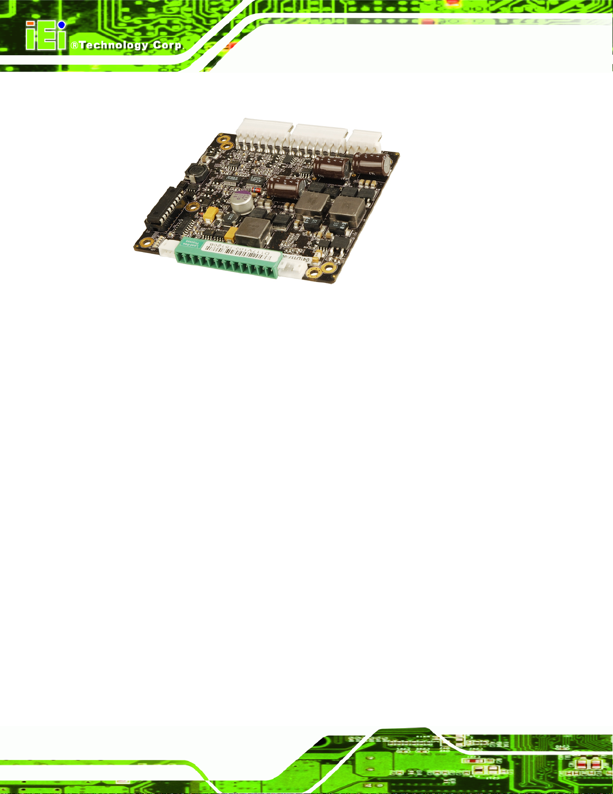
1.1 PM-P006UPS Overview
Figure 1-1: PM-P006UPS DC/DC Converter Module
PM-P006UPS DC/DC Converter Module
The highly efficient, high-performance PM-P006UPS DC-to-DC converter module
provides 5V, 3.3V, 12V, -12V and 5VSB outputs. The PM-P006UPS supports up to two
Li-Polymer smart batteries to provide stable and uninterruptible power. The power module
also receives a wide range of inputs between 6V and 36V DC. The PM-P006UPS is built
on an intelligent design and provides outstanding line and load regulations. The
PM-P006UPS is capable of sustaining 90% power efficiency.
The PM-P006UPS power module also comes with the utility software that provides
information on current power source, battery status, charging status and remaining
percentage.
1.2 PM-P006UPS Power Module Features
Highly compact design
High efficiency up to 90%
Load down protection
Over voltage protection
Page 2
Over current protection
Short circuit protection
Supports up to two battery packs
Supports AT or ATX mode
Page 11
PM-P006UPS DC/DC Converter Module
RoHS compliant
I/O interface:
o SMBus/I
2
C
o RS-232
Utility software: pull data out through RS-232 to system
Total output capacity: 65W
Input Voltage: 6V to 36V DC
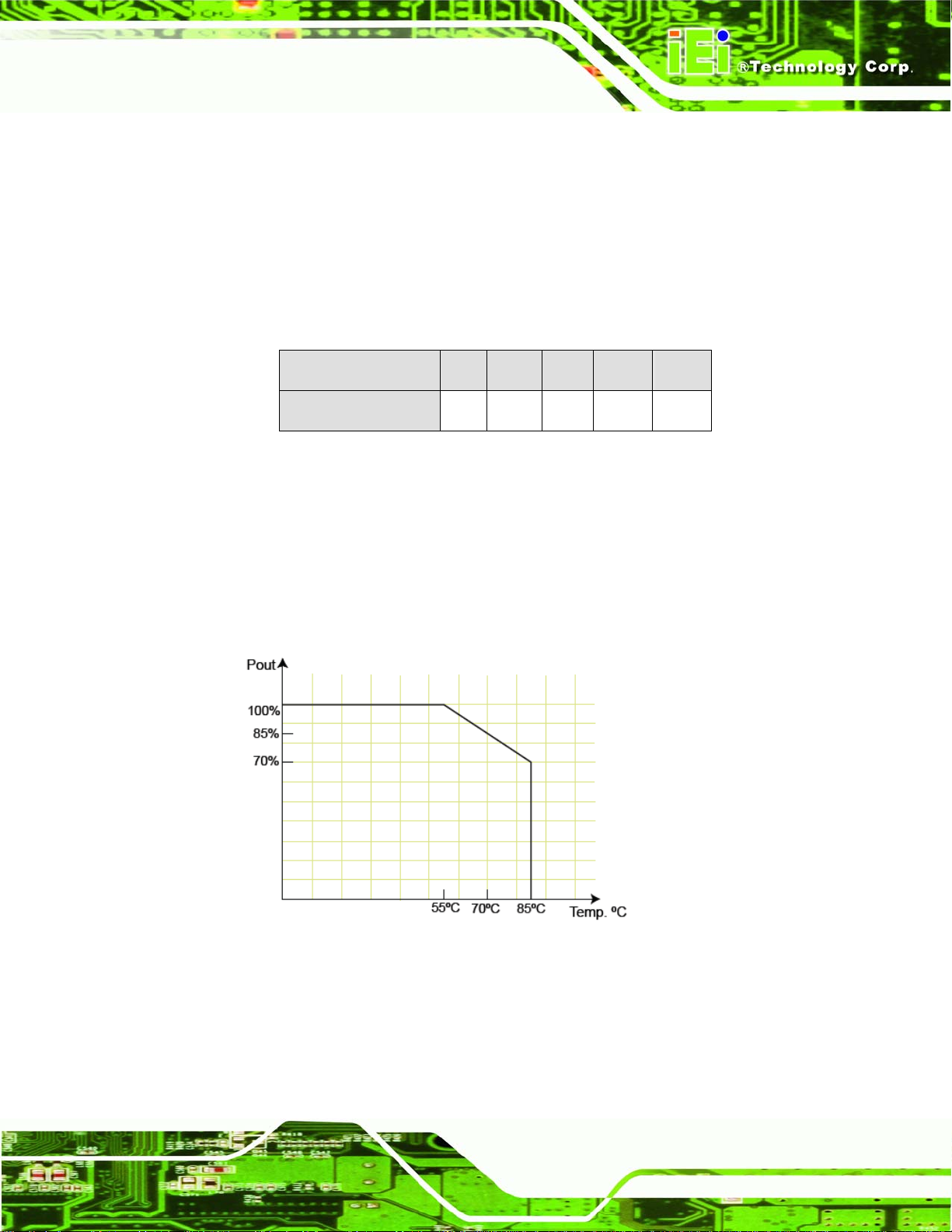
Output Voltage:
Voltage +5V +12V -12V +3.3V 5VSB
Max. Load
Table 1-1: Output Voltage
Dimensions: 90mm x 96mm
Environment:
10A 4A 0.1A 8A 1A
o Operating temperature: -20°C ~ +85°C
o Storage temperature: -40°C ~ +125°C
Weight (NW): 178g
Figure 1-2: Output Power and Temperature
Page 3
Page 12
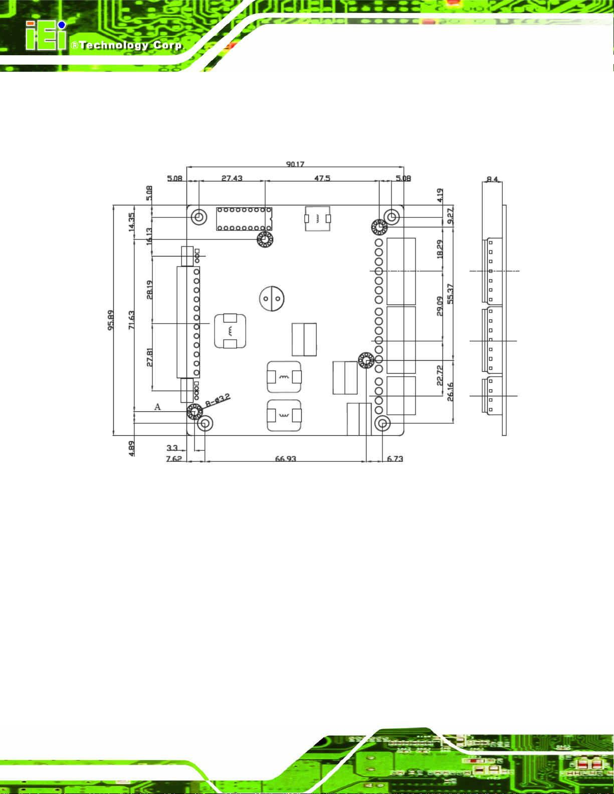
1.3 PM-P006UPS Dimensions
153H153H161HFigure 1-3 shows the PM-P006UPS dimensions. The dimensions are given in millimeters.
PM-P006UPS DC/DC Converter Module
Figure 1-3: PM-P006UPS Dimensions (mm)
Page 4
Page 13

PM-P006UPS DC/DC Converter Module
Chapter
2
2 Detailed Specifications
Page 5
Page 14
PM-P006UPS DC/DC Converter Module
2.1 PM-P006UPS System Block Diagram
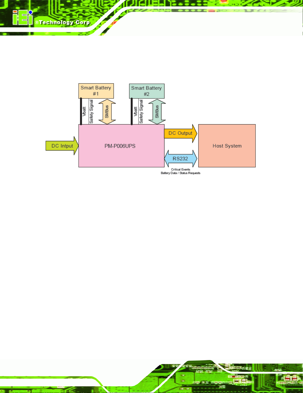
154H154H162HFigure 2-1 shows the system block diagram of the PM-P006UPS. The detailed
descriptions of the system operation are described in the following sections.
Figure 2-1: PM-P006UPS System Block Diagram
The PM-P006UPS is a charging circuit that provides the Smart Battery with charging
current and charging voltage from DC input to match the requirements from Smart Battery.
The PM-P006UPS also provides DC output power to the Host System with following
features:
Provide stable and uninterruptible power to equipment during a power outage,
line sags and spikes
Absorb power surges and transients
Smooth out noisy power sources
The PM-P006UPS receives critical events from the Smart Battery when it detects a
problem. The Smart Battery communicates with PM-P006UPS via two separate
Page 6
communication interfaces:
The SMBus CLOCK and DATA lines (primary communication channel)
The secondary signaling mechanism or Safety Signal (secondary
Page 15

PM-P006UPS DC/DC Converter Module
communication channel)
The Host System (SMBus Host) requests information from the battery and then uses it to
provide the user information about the battery present state and capabilities. The Host
System (SMBus Host) also receives critical events from the Smart Battery when it detects
a problem. Using the utility software, the battery state and capabilities can be shown in the
Host System through RS-232.
2.2 Safety
Both the battery and the PM-P006UPS must agree it is safe enough to begin charging. If
the battery detects some error conditions, the charging never begins. The error conditions
might include:
battery pack voltage too high or low,
temperature out of acceptable ranges,
individual cell voltage shorted.
Furthermore, to continue charging, both the battery and the PM-P006UPS must be
satisfied it is still safe to do so. The battery sends a message or stop sending messages to
the PM-P006UPS to terminate charge if any error condition occurs in the battery. Second,
the PM-P006UPS monitors the battery pack Safety Signal terminal. If the Safety Signal
moves out of a range that allows charging, the PM-P006UPS immediately terminates
charge. This could happen if the temperature of the battery pack got too hot.
These mechanisms are independent of and in addition to any protection mechanisms in
the battery pack itself, for example, fuses or protection FETs controlled by hard-wired
safety circuitry.
Page 7
Page 16

2.3 Battery Specifications
The PM-P006UPS may also come with a Li-Polymer smart battery. Some of the
PM-P006UPS DC/DC Converter Module
Li-Polymer smart battery specifications are listed in
Battery Type
Nominal Capacity
Nominal Voltage
Main Board
Max. Output Power
Max. Output Current
Housing
Dimensions
Operating Temperature
Weight
Li-Polymer
3000mAH
7.4V (Two 3.7V Li-Polymer battery cell)
Dual-cell Li-Ion battery PCB, Gauge IC and NTC 10KΩ
100W
16.7AH
DR202
148mm x 89mm x 20mm
-20°C ~ +60°C
230g
155H155H163HTable 2-1.
Table 2-1: BAT-LI-2S1P3000 Specifications
Page 8
Page 17

PM-P006UPS DC/DC Converter Module
Chapter
3
3 Unpacking
Page 9
Page 18

3.1 Anti-static Precautions
WARNING:
Failure to take ESD precautions during the installation of the
PM-P006UPS may result in permanent damage to the PM-P006UPS
and severe injury to the user.
Electrostatic discharge (ESD) can cause serious damage to electronic components,
including the PM-P006UPS. Dry climates are especially susceptible to ESD. It is therefore
critical that whenever the PM-P006UPS, or any other electrical component is handled, the
following anti-static precautions are strictly adhered to.
PM-P006UPS DC/DC Converter Module
Wear an anti-static wristband: Wearing a simple anti-static wristband can
help to prevent ESD from damaging the board.
Self-grounding: Before handling the board touch any grounded conducting
material. During the time the board is handled, frequently touch any
conducting materials that are connected to the ground.
Use an anti-static pad: When configuring the PM-P006UPS, place it on an
antic-static pad. This reduces the possibility of ESD damaging the
PM-P006UPS.
Only handle the edges of the PCB: When handling the PCB, hold the PCB
by the edges.
3.2 Unpacking
3.2.1 Unpacking Precautions
When the PM-P006UPS is unpacked, please do the following:
Follow the anti-static precautions outlined in Section 156H156H164H3.1.
Page 10
Make sure the packing box is facing upwards so the PM-P006UPS does not
fall out of the box.
Make sure all the components shown in Section 157H157H165H3.3 are present.
Page 19

PM-P006UPS DC/DC Converter Module
3.3 Unpacking Checklist
NOTE:
If some of the components listed in the checklist below are missing,
please do not proceed with the installation. Contact the IEI reseller or
vendor you purchased the PM-P006UPS from or contact an IEI sales
representative directly. To contact an IEI sales representative, please
send an email to
76H76H80Hsales@iei.com.tw.
3.3.1 Package Contents
The PM-P006UPS is shipped with the following components:
Quantity Item Image
1 PM-P006UPS DC/DC converter module
1
1 Utility software CD
RS-232 cable (P/N: 32100-157200-RS)
1 QIG (Quick Installation Guide)
Table 3-1: Package List Contents
Page 11
Page 20

PM-P006UPS DC/DC Converter Module
3.3.2 Optional Items
NOTE:
The items listed in this section are optional items that must be ordered
separately. Please contact your PM-P006UPS vendor, distributor or
reseller for more information or, contact iEi directly by sending an email
to
77H77H81Hsales@iei.com.tw.
The following optional items are available for the PM-P006UPS.
Quantity Item and Part Number Image
1 Li-Polymer Smart Battery, 2S1P,
3000mAH
(P/N: BAT-LI-2S1P3000)
DC Input Cable
1 Cable for following AC-DC adapters
-FSP0601AD101C 60W
-UP0451E12P 45W
-UP0251E12PL 25W
(P/N: CB-P1LP4-RS)
1 Cable for 63000-FSP120AAB-RS
120W AC-DC adapter
(P/N: CB-MD4P4-RS)
Page 12
1 Cable for Terminal Block
(P/N: CB-NOLP4-RS)
Page 21

PM-P006UPS DC/DC Converter Module
Power On/Off Cable
1 Cable to SBC (Power ok and 5VSB)
(P/N: CB-JST3PSW001-RS)
Table 3-2: Optional Items
Page 13
Page 22

PM-P006UPS DC/DC Converter Module
THIS PAGE IS INTENTIONALLY LEFT BLANK
Page 14
Page 23

PM-P006UPS DC/DC Converter Module
Chapter
4
4 Connector Pinouts
Page 15
Page 24

PM-P006UPS DC/DC Converter Module
4.1 Peripheral Interface Connectors
Section 158H158H166H4.1.1 shows peripheral interface connector locations. Section 159H159H167H4.1.2 lists all the
peripheral interface connectors seen in Section
160H160H168H4.1.1.
4.1.1 PM-P006UPS Layout
161H161H169HFigure 4-1 shows the on-board peripheral connectors of PM-P006UPS.
4.1.2 Peripheral Interface Connectors
Page 16
Figure 4-1: PM-P006UPS Connector Locations
162H162H170HTable 4-1 shows a list of the peripheral interface connectors on the PM-P006UPS.
Detailed descriptions of these connectors can be found below.
Connector Type Label
ATX mode connector 4-pin wafer connector CN2
Battery connector (1) 7-pin wafer connector J1
Page 25

PM-P006UPS DC/DC Converter Module
Battery connector (2) 7-pin wafer connector J2
Input power connector 4-pin wafer connector CN1
Output power connector 12-pin connector CN7
RS-232 cable connector 3-pin wafer connector JP2
Table 4-1: Peripheral Interface Connectors
4.2 Internal Peripheral Connectors
Internal peripheral connectors are found on the motherboard and are only accessible
when the motherboard is outside of the chassis. This section has complete descriptions of
all the internal, peripheral connectors on the PM-P006UPS.
4.2.1 ATX Mode Connector
CN Label: CN2
CN Type:
CN Location: See
CN Pinout s: See
4-pin wafer connector (1x4)
163H163H171HFigure 4-2
164H164H172HTable 4-2
Connect the ATX Mode Connector (CN2) to the motherboard to use ATX mode to control
power on/off.
Page 17
Page 26

PM-P006UPS DC/DC Converter Module
Figure 4-2: ATX Mode Connector Location
PIN NO. DESCRIPTION
1 PWROK
2 5VSB
3 GROUND
4 PS_ON
Table 4-2: ATX Mode Connector Pinouts
Use either one of the following cable to connect CN2 with motherboard:
Cable to SBC (Power ok and 5VSB)
(P/N: CB-JST3PSW001-RS)
Table 4-3: CN2 Connector Cable
Page 18
Page 27
PM-P006UPS DC/DC Converter Module
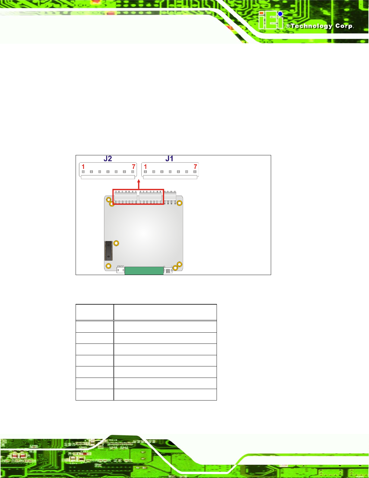
4.2.2 Battery Connectors
CN Label: J1, J2
CN Type:
CN Location: See
CN Pinouts: See
7-pin wafer connector (1x7)
165H165H173HFigure 4-3
166H166H174HTable 4-4
This connector is connected to the smart battery.
Figure 4-3: Battery Connector Locations
PIN NO. DESCRIPTION
1 BAT+
2 BAT+
3 Clock
4 DATA
5 Temp
6 GROUND
7 GROUND
Table 4-4: Battery Connector Pinouts
Page 19
Page 28

PM-P006UPS DC/DC Converter Module
Figure 4-4: Battery Connected
4.2.3 Input Power Connector
CN Label: CN1
CN Type:
CN Location: See
CN Pinouts: See
4-pin wafer connector (1x4)
167H167H175HFigure 4-5
168H168H176HTable 4-5
The input power connector is connected to power source, such as a power adapter or a
terminal block.
Page 20
Figure 4-5: Input Power Connector Location
Page 29

PM-P006UPS DC/DC Converter Module
PIN NO. DESCRIPTION
1 VIN
2 VIN
3 GROUND
4 GROUND
Table 4-5: Input Power Connector Pinouts
Use either one of the following cables to connect CN1 with power source:
Cable for following AC-DC
adapters
-FSP0601AD101C 60W
-UP0451E12P 45W
-UP0251E12PL 25W
(P/N: CB-P1LP4-RS)
Cable for 63000-FSP120AAB-RS
120W AC-DC adapter
(P/N: CB-MD4P4-RS)
Cable for Terminal Block
(P/N: CB-NOLP4-RS)
Table 4-6: CN1 Connector Cables
4.2.4 Output Power Connectors
CN Label: CN7
CN Type:
CN Location: See
CN Pinouts: See
12-pin connector (1x12)
169H169H177HFigure 4-6
170H170H178HTable 4-7
Page 21
Page 30

PM-P006UPS DC/DC Converter Module
The power module provides power to devices through this output power connector.
Figure 4-6: Output Power Connector Locations
PIN NO. DESCRIPTION
1 N12V
2 GROUND
3 +12V
4 GROUND
5 3V
6 3V
7 GROUND
8 5V
9 5V
10 GROUND
11 5V_SB
Page 22
12 GROUND
Table 4-7: Output Power Connector Pinouts
Page 31

PM-P006UPS DC/DC Converter Module
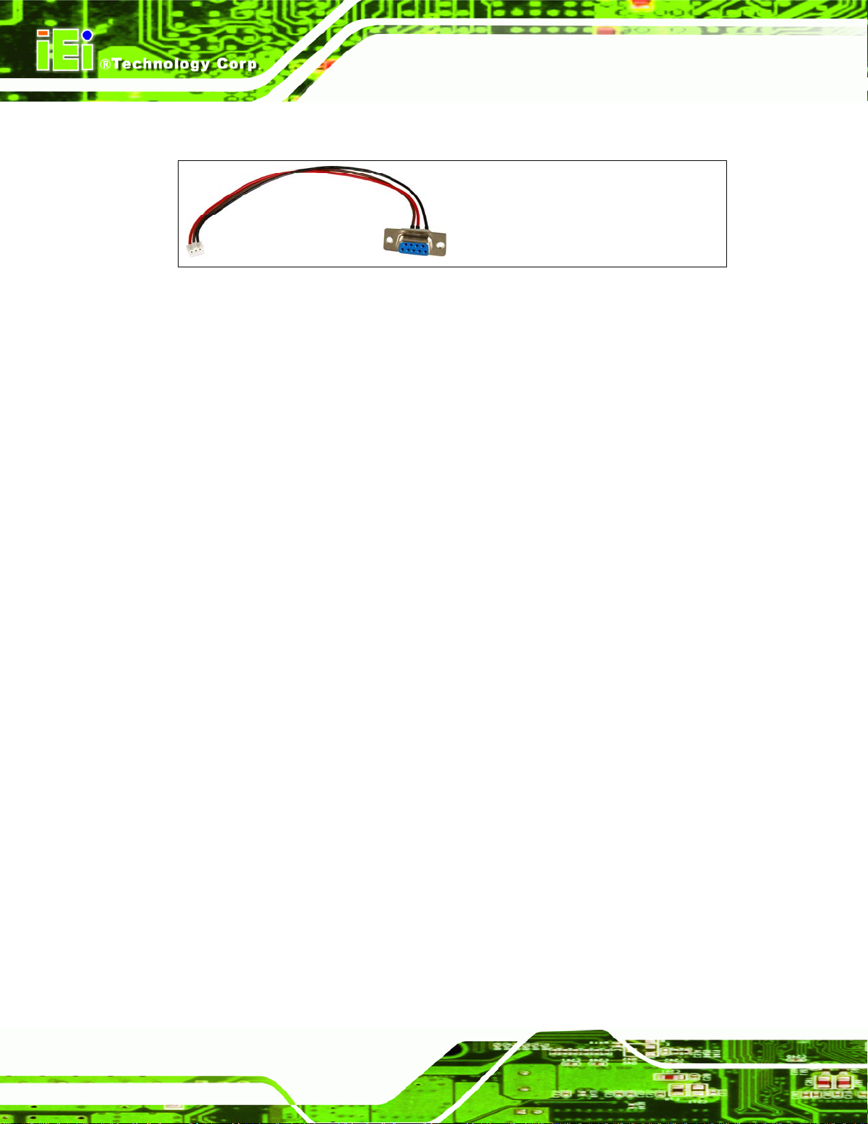
4.2.5 RS-232 Cable Connector
CN Label: JP2
CN Type:
CN Location: See
CN Pinouts: See
3-pin wafer connector (1x3)
171H171H179HFigure 4-7
172H172H180HTable 4-8
This connector enables the PM-P006UPS to communicate with the SBC through RS-232
serial port.
Figure 4-7: RS-232 Cable Connector Location
PIN NO. DESCRIPTION
1 GROUND
2 TX
3 RX
Table 4-8: RS-232 Cable Connector Pinouts
Page 23
Page 32
PM-P006UPS DC/DC Converter Module
Use the following cable to connect JP2 with the serial port of the SBC.
Figure 4-8: JP2 Connector Cable (RS-232 cable)
Page 24
Page 33

PM-P006UPS DC/DC Converter Module
Chapter
5
5 Software Application
Page 25
Page 34

PM-P006UPS DC/DC Converter Module
5.1 Introduction
The IEI IDDUPS Battery Status Monitor application detects the information of the smart
battery and monitors the battery status. It is recommended to execute this IDDUPS
application in Windows XP SP2 environment.
5.2 Monitoring DC Power and Smart Battery
5.2.1 Using the Application
Follow the steps below to start the IDDUPS Battery application.
Step 1: Use the RS-232 cable to connect the JP2 connector on the PM-P006UPS to the
serial port of the SBC. Please refer to Section
173H173H181H4.2.5 for the location of the JP2
connector.
Step 2: Insert the application CD that comes with PM-P006UPS.
Step 3: Double click the IDDUPS.exe icon (
174H174H182HFigure 5-1).
Figure 5-1: IDDUPS Battery Status Monitor Application
Step 4: Click the SETTING tab when the IDDUPS Battery application is loaded
183HFigure 5-2).
(
Page 26
Page 35
PM-P006UPS DC/DC Converter Module
Figure 5-2: IDDUPS Battery Application - Setting
Step 5: Select the label of the connected serial port of the SBC (184HFigure 5-3).
Figure 5-3: Serial Port Selection
Page 27
Page 36

PM-P006UPS DC/DC Converter Module
Step 6: Press open to activate the selected serial port. The Com Port Status on the
application shows the selected COM port is open (
185HFigure 5-4).
Figure 5-4: Activate the Connected Serial Port
5.2.2 Status Information
The IEI IDDUPS Battery Status Monitor application shows the DC power status and
battery status (
details.
175H175H186HFigure 5-5). The following sections describe the status information in
Page 28
Page 37

PM-P006UPS DC/DC Converter Module
Figure 5-5: Status Information
5.2.2.1 DC Detection
When the DC power is connected to the PM-P006UPS power module, the IDDUPS
Battery Status Monitor detects it and shows in the screen as
176H176H187HFigure 5-6.
Figure 5-6: DC Detection
5.2.2.2 Battery Detection
When the smart battery is connected to the PM-P006UPS power module, the IDDUPS
Battery Status Monitor detects it and shows in the screen as
can be connected to the PM-P006UPS power module at the same time. The second
177H177H188HFigure 5-7. Two batteries
battery information is shown in the Battery B Detection section if connected.
Page 29
Page 38

PM-P006UPS DC/DC Converter Module
Figure 5-7: Battery Detection
On The battery is connected to the PM-P006UPS.
Off The battery is not connected to the
Battery Full The battery is fully charged.
Battery Low The battery is low.
Using The battery is being used.
PM-P006UPS.
Charging The battery is being charged.
Standby The battery is fully charged and ready to be used
anytime.
>60 C The battery temperature is above 60°C.
<60 C The battery temperature is below 60°C.
5.2.2.3 Battery Remaining Time
The battery remaining time is shown in the top right corner (178H178H189HFigure 5-8) of the status
screen to indicate the total battery remaining time. To view the individual battery time, click
on the BATTERY A or BATTERY B tab (Section
179H179H190H5.2.3).
Figure 5-8: Battery Remaining Time
Page 30
Page 39

PM-P006UPS DC/DC Converter Module
5.2.3 Battery Information
Click on the BATTERY A or BATTERY B tab to view the information of battery A or battery
B. The listed information includes battery type, capacity, output voltage, temperature,
charging rate, discharging rate and battery remaining time (
are updated per second.
180H180H191HFigure 5-9). The values listed
Figure 5-9: Battery Information
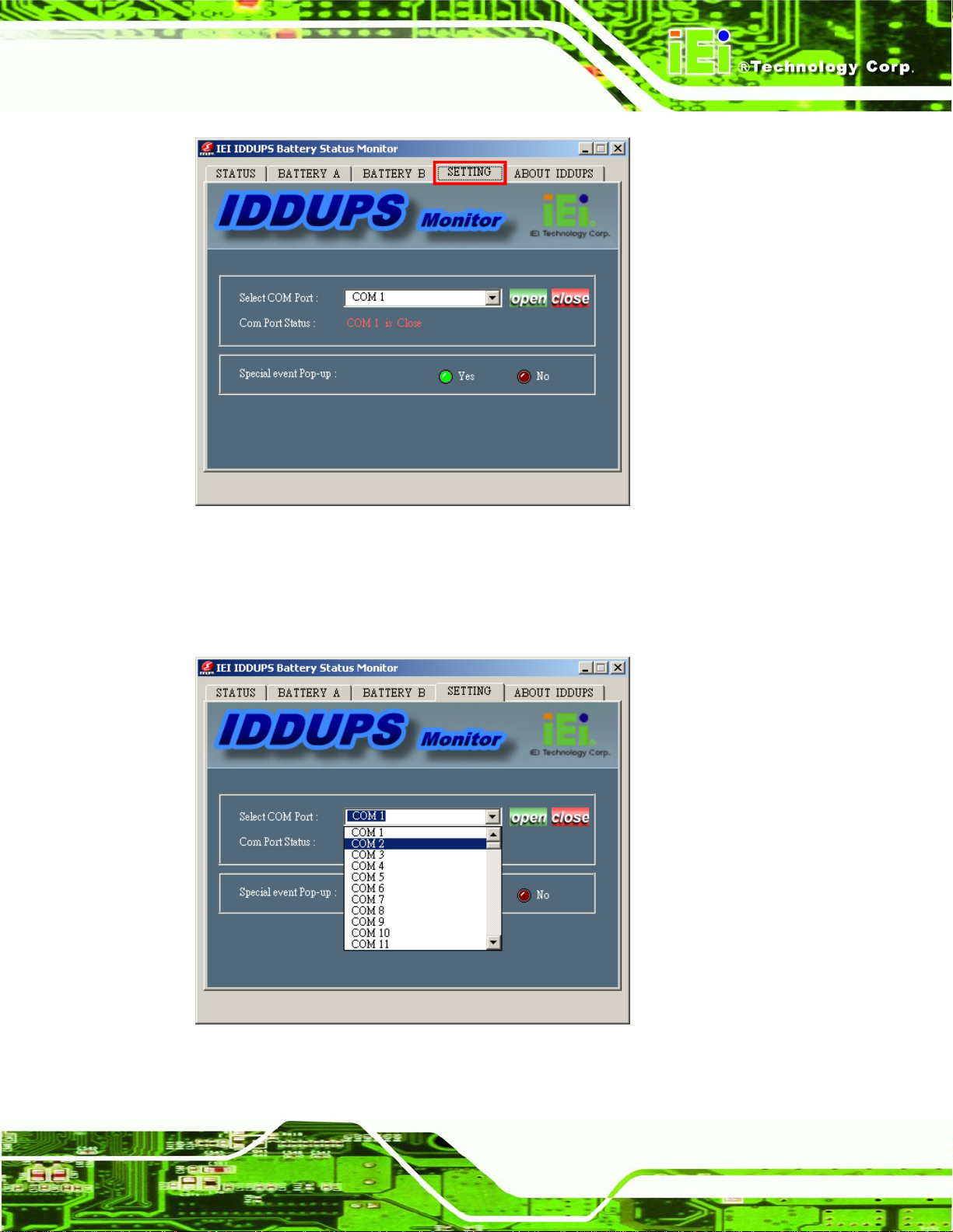
5.2.4 Setting
Click on the SETTING tab to select the COM port or enable/disable the special event
pop-up window (
181H181H192HFigure 5-10).
Page 31
Page 40

PM-P006UPS DC/DC Converter Module
Figure 5-10: Application Setting
When the IDDUPS Battery Status Monitor application starts up, the user need to click the
SETTING tab to select the connected COM port of the SBC and activate the COM port by
clicking the open button. Please refer to Section
182H182H194HFigure 5-11 shows the COM 2 is open by the user for connecting the PM-P006UPS to the
SBC.
193H5.2.1 for step-by-step description.
Page 32
Page 41

PM-P006UPS DC/DC Converter Module
Figure 5-11: COM Port Status
The IDDUPS Battery Status Monitor application will notify users with pop-up window if
some special events happen, such as battery low or temperature over 60°C. This function
can be enabled or disabled. Click Yes to enable or click No to disable (
Figure 5-12: Special Event Pop-up Setting
5.3 System Log
The IDDUPS application provides easy access to the system log. To view the system log,
right click the icon in the quick launch toolbar on the desktop as shown in
select System Log.
183H183H195HFigure 5-12).
184H184H196HFigure 5-13 and
Page 33
Page 42

PM-P006UPS DC/DC Converter Module
Figure 5-13: IDDUPS Application Quick Launch Icon
After clicking on the System Log, a screen pops-up (
that have happened.
185H185H197HFigure 5-14) and displays all events
Page 34
Figure 5-14: System Log Example
Page 43

PM-P006UPS DC/DC Converter Module
5.4 Exit
To close the IDDUPS application, right click the icon in the quick launch toolbar on the
desktop as shown in and select Exit (
186H186H198HFigure 5-15).
Figure 5-15: Exit IDDUPS Application
Page 35
Page 44

PM-P006UPS DC/DC Converter Module
THIS PAGE IS INTENTIONALLY LEFT BLANK
Page 36
Page 45

PM-P006UPS DC/DC Converter Module
Appendix
A
A Hazardous Materials
Disclosure
Page 37
Page 46

PM-P006UPS DC/DC Converter Module
A.1 Hazardous Material Disclosure Table for IPB Products Certified as RoHS Compliant Under 2002/95/EC Without Mercury
The details provided in this appendix are to ensure that the product is compliant with the
Peoples Republic of China (China) RoHS standards. The table below acknowledges the
presences of small quantities of certain materials in the product, and is applicable to China
RoHS only.
A label will be placed on each product to indicate the estimated “Environmentally Friendly
Use Period” (EFUP). This is an estimate of the number of years that these substances
would “not leak out or undergo abrupt change.” This product may contain replaceable
sub-assemblies/components which have a shorter EFUP such as batteries and lamps.
These components will be separately marked.
Please refer to the table on the next page.
Page 38
Page 47

PM-P006UPS DC/DC Converter Module
Toxic or Hazardous Substances and Elements Part Name
Lead
(Pb)
Housing
X
Display X
Printed Circuit
X
Mercury
(Hg)
O O O O
O O O O
O O O O
Board
Metal Fasteners X
Cable Assembly X
Fan Assembly X
Power Supply
X
O O O O
O O O O
O O O O
O O O O
Assemblies
Battery O
O O O O O
Cadmium
(Cd)
Hexavalent
Chromium
(CR(VI))
Polybrominated
Biphenyls
(PBB)
Polybrominated
Diphenyl Ethers
(PBDE)
X
X
X
O
X
X
X
O: This toxic or hazardous substance is contained in all of the homogeneous materials for the part is below
the limit requirement in SJ/T11363-2006
X: This toxic or hazardous substance is contained in at least one of the homogeneous materials for this part
is above the limit requirement in SJ/T11363-2006
Page 39
Page 48

此附件旨在确保本产品符合中国 RoHS 标准。以下表格标示此产品中某有毒物质的含量符
合中国 RoHS 标准规定的限量要求。
本产品上会附有”环境友好使用期限”的标签,此期限是估算这些物质”不会有泄漏或突变”的
年限。本产品可能包含有较短的环境友好使用期限的可替换元件,像是电池或灯管,这些
元件将会单独标示出来。
PM-P006UPS DC/DC Converter Module
部件名称
壳体
显示
印刷电路板
金属螺帽
电缆组装
风扇组装
电力供应组装
电池
O: 表示该有毒有害物质在该部件所有物质材料中的含量均在 SJ/T11363-2006 标准规定的限量要求以下。
有毒有害物质或元素
铅
(Pb)
X
X
X
X
X
X
X
O
汞
(Hg)
O O O O
O O O O
O O O O
O O O O
O O O O
O O O O
O O
O O O O O
镉
(Cd)
六价铬
(CR(VI))
多溴联苯
(PBB)
多溴二苯醚
(PBDE)
X
X
X
O
X
X
O
O
X
X: 表示该有毒有害物质至少在该部件的某一均质材料中的含量超出 SJ/T11363-2006 标准规定的限量要求。
Page 40
Page 49

PM-P006UPS DC/DC Converter Module
B Index
Page 41
Page 50

PM-P006UPS DC/DC Converter Module
A
anti-static precautions, 10
anti-static pad, 10
anti-static wristband, 10
handling, 10
self-grounding, 10
C
connectors, pinouts and location
ATX Mode, 17
Battery Connectors, 19
Input power, 20
Output power, 21
SBC main power, 23
D
O
output power, 22
Output Voltage, 3
Over current protection, 2
Over voltage protection, 2
P
peripheral connectors, 17
power adapter, 20
R
RS-232, 3, 7
S
Short circuit protection, 2
Dimensions, 3, 4, 8
E
electrostatic discharge, 10
I
Input Voltage, 3
L
Load down protection, 2
Smart Battery, iv, 6, 7, 12
SMBus, 3, 6, 7
Specifications, 8
Battery, 8
T
terminal block, 20
U
unpacking, 10
unpacking checklist, 11
unpacking precautions, 10
Page 42
 Loading...