

Page 1
PM-945GSE-N270 User Manual
IEI Technology Corp.
MODEL:
PM-945GSE-N270
PCI-104 SBC with Intel® Atom N270 1.6 GHz CPU, Ethernet,
USB 2.0, Audio, CF Card Type 2, RS-232, RS-422/485, IDE,
RoHS Compliant
User Manual
Rev. 1.02 – 17 August, 2011
Page i
Page 2

PM-945GSE-N270 User Manual
Revision
Date Version Changes
17 August, 2011 1.02 Minor revision to Figure 3-4: ATX Power Supply Enable
Connector Location
Updated formatting throughout document
26 March, 2010 1.01 Minor edit
28 August, 2009 1.00 Initial release
Page ii
Page 3
PM-945GSE-N270 User Manual
COPYRIGHT NOTICE
The information in this document is subject to change without prior notice in order to
improve reliability, design and function and does not represent a commitment on the part
of the manufacturer.
In no event will the manufacturer be liable for direct, indirect, special, incidental, or
consequential damages arising out of the use or inability to use the product or
documentation, even if advised of the possibility of such damages.
This document contains proprietary information protected by copyright. All rights are
Copyright
reserved. No part of this manual may be reproduced by any mechanical, electronic, or
other means in any form without prior written permission of the manufacturer.
TRADEMARKS
All registered trademarks and product names mentioned herein are used for identification
purposes only and may be trademarks and/or registered trademarks of their respective
owners.
Page iii
Page 4
PM-945GSE-N270 User Manual
Table of Contents
1 INTRODUCTION........................................................................................................ 13
1.1 INTRODUCTION......................................................................................................... 14
1.1.1 Applications ..................................................................................................... 14
1.1.2 Benefits............................................................................................................. 14
1.1.3 Features ........................................................................................................... 15
1.2 OVERVIEW................................................................................................................ 16
1.2.1 Connectors....................................................................................................... 17
1.3 DIMENSIONS............................................................................................................. 19
1.4 DATA FLOW.............................................................................................................. 20
1.4.1 Technical Specifications................................................................................... 20
2 UNPACKING............................................................................................................... 23
2.1 ANTI-STATIC PRECAUTIONS...................................................................................... 24
2.2 UNPACKING PRECAUTIONS....................................................................................... 24
2.3 UNPACKING CHECKLIST ........................................................................................... 25
2.3.1 Package Contents............................................................................................. 25
2.4 OPTIONAL ITEMS...................................................................................................... 26
3 CONNECTORS ........................................................................................................... 27
PERIPHERAL INTERFACE CONNECTORS..................................................................... 28
3.1
3.1.1 PM-945GSE-N270 Motherboard Layout......................................................... 28
3.1.2 Peripheral Interface Connectors ..................................................................... 29
3.2
INTERNAL PERIPHERAL CONNECTORS ...................................................................... 30
3.2.1 12V / 5V Power Connector.............................................................................. 30
3.2.2 ATX Power Supply Enable Connector............................................................. 31
3.2.3 Audio Kit Connector........................................................................................ 32
3.2.4 Battery Connector............................................................................................ 33
3.2.5 CompactFlash® Connector............................................................................. 34
3.2.6 Fan Connector................................................................................................. 36
3.2.7 Digital I/O Connector...................................................................................... 37
3.2.8 Keyboard/Mouse Connector............................................................................ 37
Page iv
Page 5

PM-945GSE-N270 User Manual
3.2.9 LAN Connector ................................................................................................ 38
3.2.10 LCD Inverter Connector................................................................................ 39
3.2.11 LED and +5V Output Connector................................................................... 40
3.2.12 PCI-104 Connector........................................................................................ 41
3.2.13 Power Button Connector................................................................................ 43
3.2.14 Reset Button Connector ................................................................................. 44
3.2.15 RS-232 Serial Port Connectors...................................................................... 45
3.2.16 RS-422/485 Serial Port Connector................................................................ 46
3.2.17 LVDS LCD Connector ................................................................................... 47
3.2.18 SATA Drive Connector................................................................................... 48
3.2.19 SPI Flash Connector...................................................................................... 49
3.2.20 USB Connector .............................................................................................. 50
3.2.21 VGA Connector.............................................................................................. 50
4 INSTALLATION ......................................................................................................... 52
4.1 ANTI-STATIC PRECAUTIONS...................................................................................... 53
4.2 INSTALLATION CONSIDERATIONS.............................................................................. 54
4.2.1 Installation Notices.......................................................................................... 54
4.2.2 Installation Checklist....................................................................................... 55
4.3 UNPACKING.............................................................................................................. 56
4.4 COMPACTFLASH® CARD INSTALLATION.................................................................. 56
4.5 JUMPER SETTINGS .................................................................................................... 57
4.5.1 Clear CMOS Jumper........................................................................................ 59
4.5.2 COM3 RS-232/422/RS485 Select Jumper........................................................ 59
4.5.3 LVDS Voltage Select Jumper............................................................................ 60
4.5.4 PCI-104 Voltage Setup..................................................................................... 61
CHASSIS INSTALLATION............................................................................................ 62
4.6
4.7 INTERNAL PERIPHERAL DEVICE CONNECTIONS........................................................ 62
4.7.1 Keyboard/Mouse Y-cable Connector ............................................................... 63
4.7.2 LVDS LCD Installation.................................................................................... 64
4.7.3 SATA Drive Connection ................................................................................... 66
4.7.4 Four Serial Port Connector............................................................................. 68
4.7.5 USB Cable (Dual Port without Bracket) ......................................................... 69
4.8 SOFTWARE INSTALLATION ........................................................................................ 70
5 BIOS.............................................................................................................................. 73
Page v
Page 6

INTRODUCTION......................................................................................................... 74
5.1
PM-945GSE-N270 User Manual
5.1.1 Starting Setup................................................................................................... 74
5.1.2 Using Setup...................................................................................................... 74
5.1.3 Getting Help..................................................................................................... 75
5.1.4 Unable to Reboot After Configuration Changes.............................................. 75
5.1.5 BIOS Menu Bar................................................................................................ 75
5.2 MAIN........................................................................................................................ 76
5.3 ADVANCED............................................................................................................... 77
5.3.1 CPU Configuration.......................................................................................... 78
5.3.2 IDE Configuration........................................................................................... 79
5.3.2.1 IDE Master, IDE Slave............................................................................. 81
5.3.3 Super I/O Configuration
.................................................................................. 85
5.3.4 Hardware Health Configuration...................................................................... 88
5.3.5 Power Configuration ....................................................................................... 90
5.3.6 Remote Access Configuration.......................................................................... 90
5.3.7 USB Configuration........................................................................................... 93
5.4 PCI/PNP................................................................................................................... 95
5.5 BOOT SETTINGS CONFIGURATION ............................................................................ 97
5.5.1 Boot Settings Configuration............................................................................. 97
5.5.2 Boot Device Priority........................................................................................ 99
5.5.3 Hard Disk Drives........................................................................................... 100
5.5.4 Removable Drives.......................................................................................... 100
5.5.5 CD/DVD Drives............................................................................................. 101
SECURITY............................................................................................................... 102
5.6
5.7 CHIPSET ................................................................................................................. 103
5.7.1 Northbridge Chipset Configuration............................................................... 104
5.7.2 Southbridge Configuration ............................................................................ 107
5.8 EXIT....................................................................................................................... 108
A BIOS OPTIONS .........................................................................................................110
B TERMINOLOGY.......................................................................................................113
C WATCHDOG TIMER ...............................................................................................116
D HAZARDOUS MATERIALS DISCLOSURE........................................................119
D.1 HAZARDOUS MATERIALS DISCLOSURE TABLE FOR IPB PRODUCTS CERTIFIED AS
Page vi
Page 7
PM-945GSE-N270 User Manual
OHS COMPLIANT UNDER 2002/95/EC WITHOUT MERCURY ..................................... 120
R
Page vii
Page 8
PM-945GSE-N270 User Manual
List of Figures
Figure 1–1: PM-945GSE-N270 .....................................................................................................14
Figure 1-2: PM-945GSE-N270 Motherboard Overview..............................................................16
Figure 1-3: PM-945GSE-N270 Motherboard Solder Side Overview.........................................17
Figure 1-4: PM-945GSE-N270 Dimensions (mm).......................................................................19
Figure 1-5: Data Flow Block Diagram.........................................................................................20
Figure 3-1: Connector and Jumper Locations (Front Side) .....................................................28
Figure 3-2: Connector and Jumper Locations (Solder Side) ...................................................29
Figure 3-3: 12V / 5V Power Connector Location .......................................................................31
Figure 3-4: ATX Power Supply Enable Connector Location....................................................32
Figure 3-5: Audio Kit Connector Location.................................................................................33
Figure 3-6: Battery Connector Location.....................................................................................34
Figure 3-7: CompactFlash® Connector Location......................................................................35
Figure 3-8: Fan Connector Location...........................................................................................36
Figure 3-9: Digital I/O Connector Locations ..............................................................................37
Figure 3-10: Keyboard/Mouse Connector Location..................................................................38
Figure 3-11: LAN Connector Location........................................................................................39
Figure 3-12: LCD Inverter Connector Location .........................................................................40
Figure 3-13: LED Connector Locations......................................................................................41
Figure 3-14: PCI-104 Connector Location..................................................................................42
Figure 3-15: Power Button Connector Location........................................................................44
Figure 3-16: Reset Button Connector Location.........................................................................44
Figure 3-17: RS-232 Serial Port Connector Locations..............................................................45
Figure 3-18: RS-422/485 Serial Port Connector Location.........................................................46
Figure 3-19: LVDS LCD Connector Locations...........................................................................47
Figure 3-20: SATA Drive Connector Location...........................................................................48
Figure 3-21: SPI Flash Connector...............................................................................................49
Figure 3-22: USB Connector Pinout Locations.........................................................................50
Figure 3-23: VGA Connector Location .......................................................................................51
Figure 4-1: CompactFlash® Card Installation ...........................................................................57
Figure 4-2: Jumper Locations.....................................................................................................58
Page viii
Page 9

PM-945GSE-N270 User Manual
Figure 4-3: Clear BIOS Jumper Location ...................................................................................59
Figure 4-4: COM3 RS-232/422/RS485 Select Jumper Location................................................60
Figure 4-5: LVDS Voltage Select Jumper Location...................................................................61
Figure 4-6: PCI-104 Voltage Jumper Location...........................................................................61
Figure 4-7: Keyboard/mouse Y-cable Connection....................................................................64
Figure 4-8: LVDS Connector........................................................................................................65
Figure 4-9: Backlight Inverter Connection.................................................................................66
Figure 4-10: SATA Drive Cable Connection...............................................................................67
Figure 4-11: SATA Power Drive Connection..............................................................................68
Figure 4-12: Four Serial Port Connector....................................................................................69
Figure 4-13: Serial Device Connector.........................................................................................69
Figure 4-14: Dual USB Cable Connection..................................................................................70
Figure 4-15: Introduction Screen................................................................................................71
Figure 4-16: Available Drivers.....................................................................................................72
Page ix
Page 10

PM-945GSE-N270 User Manual
List of Tables
Table 1-1: PM-945GSE-N270 Specifications..............................................................................22
Table 2-1: Package List Contents...............................................................................................26
Table 2-2: Package List Contents (Optional Items)...................................................................26
Table 3-1: Peripheral Interface Connectors...............................................................................30
Table 3-2: 12V / 5V Power Connector Pinouts...........................................................................31
Table 3-3: ATX Power Supply Enable Connector Pinouts .......................................................32
Table 3-4: Audio Kit Connector Pinouts.....................................................................................33
Table 3-5: Battery Connector Pinouts........................................................................................34
Table 3-6: CompactFlash® Connector Pinouts.........................................................................36
Table 3-7: Fan Connector Pinouts..............................................................................................36
Table 3-8: Digital I/O Connector Pinouts....................................................................................37
Table 3-9: Keyboard/Mouse Connector Pinouts .......................................................................38
Table 3-10: LAN Connector Pinouts...........................................................................................39
Table 3-11: LCD Inverter Connector Pinouts.............................................................................40
Table 3-12: LED Connector Pinouts ...........................................................................................41
Table 3-13: PCI-104 Connector Pinouts .....................................................................................43
Table 3-14: Power Button Connector Pinouts...........................................................................44
Table 3-15: Reset Button Connector Pinouts............................................................................45
Table 3-16: RS-232 Serial Port Connector Pinouts...................................................................46
Table 3-17: RS-422/RS-485 Serial Port Connector Pinouts......................................................47
Table 3-18: LVDS Connector Pinouts.........................................................................................48
Table 3-19: SATA Drive Connector Pinouts...............................................................................49
Table 3-20: SPI Flash Connector.................................................................................................50
Table 3-21: USB Port Connector Pinouts...................................................................................50
Table 3-22: VGA Connector Pinouts...........................................................................................51
Table 4-1: Clear BIOS Jumper Settings......................................................................................59
Table 4-2: COM3 RS-232/422/RS485 Select Jumper Settings..................................................60
Table 4-3: LVDS Voltage Select Jumper Settings.....................................................................60
Table 4-4: PCI-104 Voltage Jumper Settings .............................................................................61
Table 4-5: IEI Provided Cables....................................................................................................62
Page x
Page 11

PM-945GSE-N270 User Manual
Table 5-1: BIOS Navigation Keys................................................................................................75
Page xi
Page 12

PM-945GSE-N270 User Manual
BIOS Menus
BIOS Menu 1: Main.......................................................................................................................76
BIOS Menu 2: Advanced..............................................................................................................78
BIOS Menu 3: CPU Configuration...............................................................................................78
BIOS Menu 4: IDE Configuration.................................................................................................79
BIOS Menu 5: IDE Master and IDE Slave Configuration...........................................................81
BIOS Menu 6: Super IO Configuration........................................................................................86
BIOS Menu 7: Hardware Health Configuration..........................................................................89
BIOS Menu 8: APM Configuration...............................................................................................90
BIOS Menu 9: Remote Access Configuration............................................................................91
BIOS Menu 10: USB Configuration.............................................................................................93
BIOS Menu 11: PCI/PnP Configuration.......................................................................................95
BIOS Menu 12: Boot.....................................................................................................................97
BIOS Menu 13: Boot Settings Configuration.............................................................................97
BIOS Menu 14: Boot Device Priority Settings ...........................................................................99
BIOS Menu 15: Hard Disk Drives ............................................................................................. 100
BIOS Menu 16: Removable Drives........................................................................................... 101
BIOS Menu 17: CD/DVD Drives ................................................................................................ 102
BIOS Menu 18: Security............................................................................................................ 102
BIOS Menu 19: Chipset............................................................................................................. 104
BIOS Menu 20: Video Configuration........................................................................................ 104
BIOS Menu 21:Southbridge Chipset Configuration............................................................... 107
BIOS Menu 22: Exit.................................................................................................................... 108
Page xii
Page 13

PM-945GSE-N270 User Manual
Chapter
1
1 Introduction
Page 13
Page 14

1.1 Introduction
PM-945GSE-N270 User Manual
Figure 1–1: PM-945GSE-N270
The PCI-104 form factor PM-945GSE-N270 is a highly integrated embedded computer
specifically optimized for multi-media applications requiring minimum installation space.
The PM-945GSE-N270 is particularly suitable for low power and fan-less applications.
The PM-945GSE-N270 supports a full range of functions for an AT compatible industrial
computer in a space-saving 109 mm x 116 mm profile. The PM-945GSE-N270 is
equipped with an on-board low-power consumption and high performance Intel® Atom™
N270 1.6 GHz processor. It also includes 1 GB of DDR2 SDRAM memory on-board.
1.1.1 Applications
The PM-945GSE-N270 motherboard has been designed for use in industrial applications
where board expansion is critical and operational reliability is essential.
1.1.2 Benefits
Some of the PM-945GSE-N270 motherboard benefits include,
Page 14
Operating reliably in harsh industrial environments with ambient temperatures
Page 15

PM-945GSE-N270 User Manual
ranging from 0°C to 60°C
Rebooting automatically if the BIOS watchdog timer detects that the system is
no longer operating
1.1.3 Features
Some of the PM-945GSE-N270 motherboard features are listed below:
Complies with RoHS
Supports Intel® Atom™ N270 CPU
Supports a maximum front side bus (FSB) speed up to 533MHz
1 GB on-board DDR 533 SDRAM
Complete I/O support with SATA, CF Ty pe II, PCI-104, LAN, and 4 x USB2.0
and 4 x RS-232, 1 x RS-422/485 support shared with COM2
Supports 18-bit dual channel LVDS + VGA, dual independent display
Page 15
Page 16
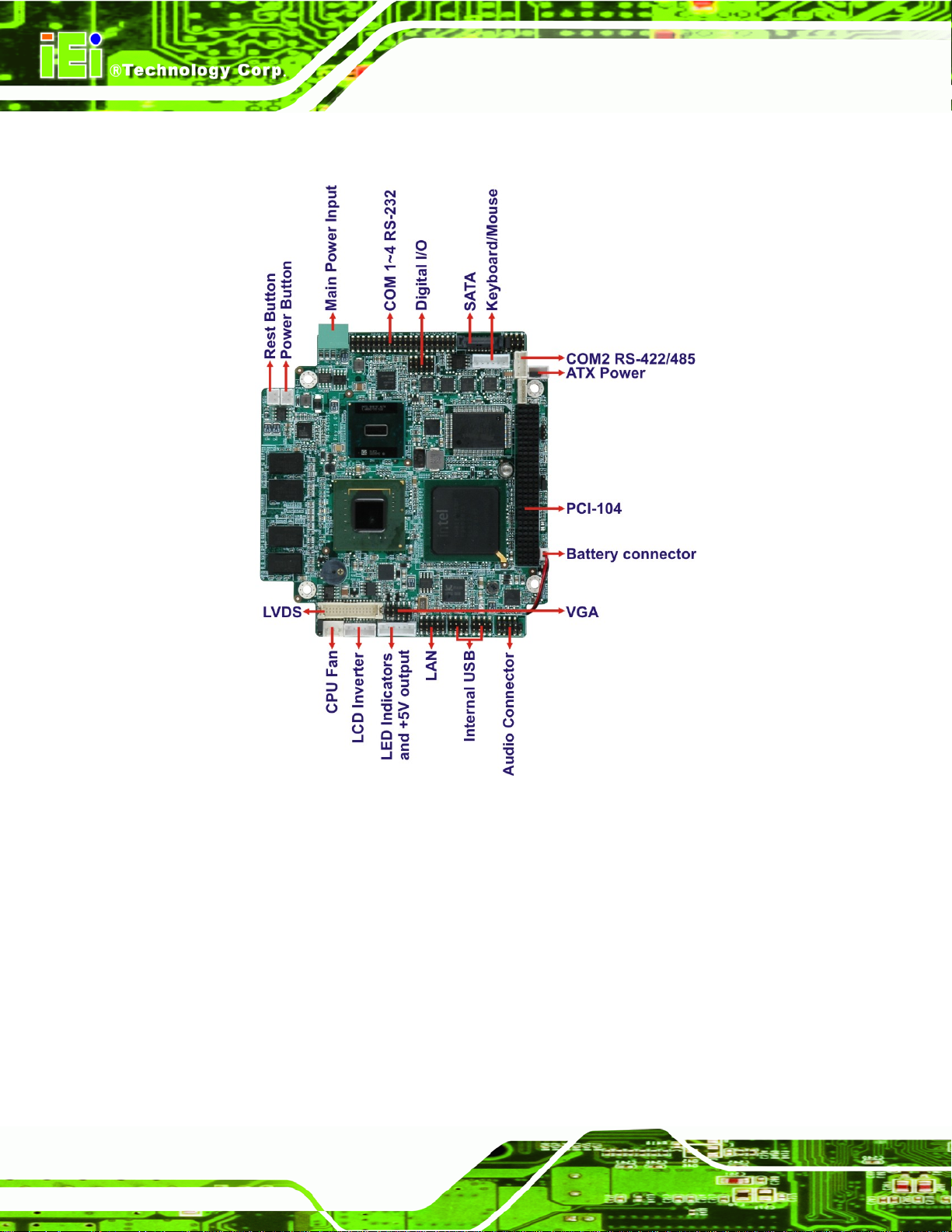
1.2 Overview
PM-945GSE-N270 User Manual
Page 16
Figure 1-2: PM-945GSE-N270 Motherboard Overview
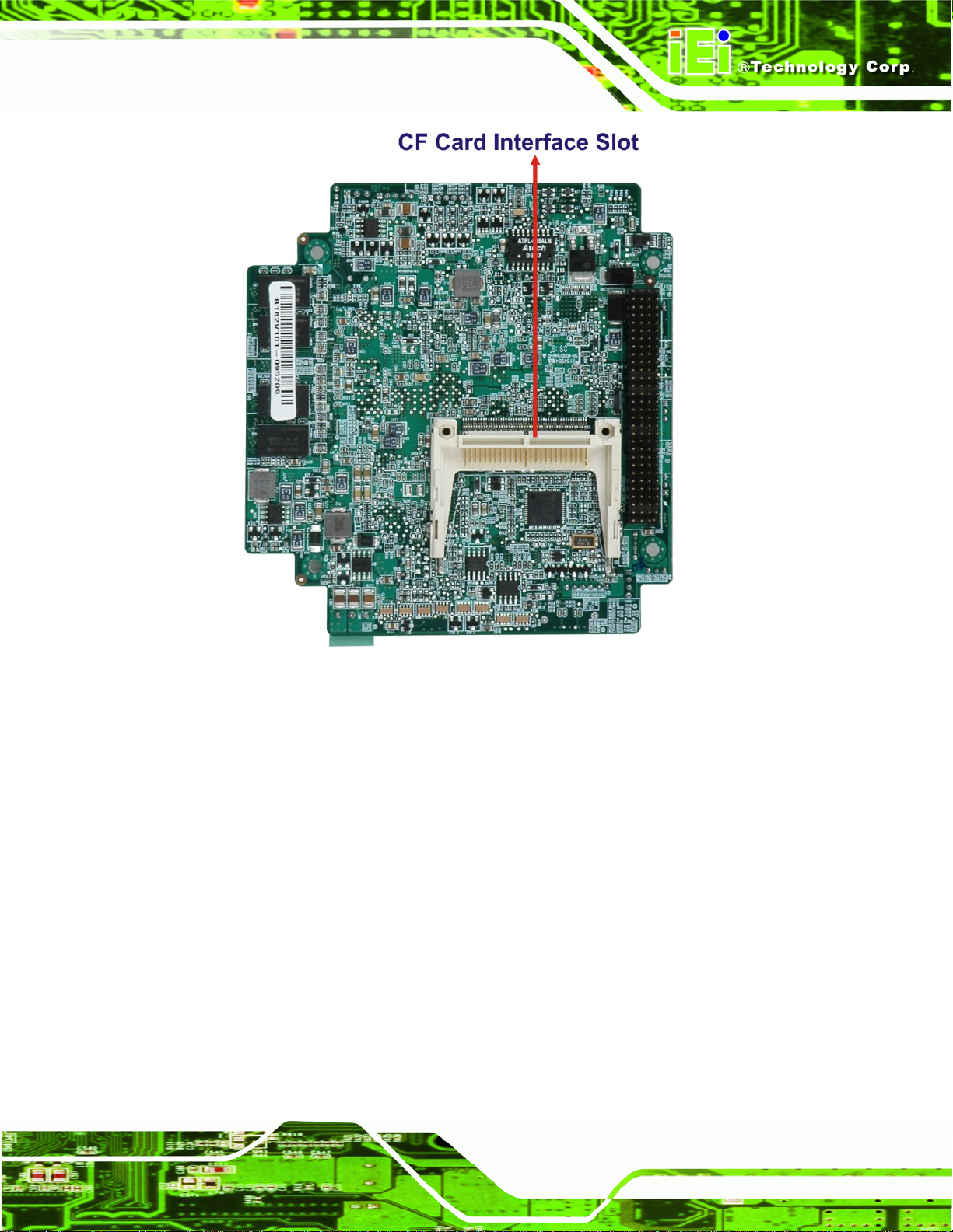
Page 17
PM-945GSE-N270 User Manual
Figure 1-3: PM-945GSE-N270 Motherboard Solder Side Overview
1.2.1 Connectors
The PM-945GSE-N270 motherboard has the following connectors on-board (described in
Chapter 3):
1 x AT/ATX 12V/5V connector
1 x CompactFlash® connector (solder side)
1 x Digital I/O connector
1 x Audio connector (supported via optional 5.1 channel audio kit with Realtek
ALC655 AC'9 7 codec or 7.1 channel HD audio kit with Realtek ALC883
codec)
1 x Keyboard/mouse connector
1 x LAN connector
1 x LCD Inverter connector
Page 17
Page 18
1 x LED connector
1 x LVDS LCD connector
1 x PCI-104 connector
4 x RS-232 connectors
1 x RS-422/485 connector (shared with COM2)
1 x SATA connector
4 x USB connectors
1 x VGA connector
PM-945GSE-N270 User Manual
Page 18
Page 19

PM-945GSE-N270 User Manual
1.3 Dimensions
The dimensions of the board are listed below:
Length: 116 mm
Width: 108.59 mm
Figure 1-4: PM-945GSE-N270 Dimensions (mm)
Page 19
Page 20

1.4 Data Flow
The PM-945GSE-N270 motherboard comes with an Intel® Atom™ N270 processor and
PM-945GSE-N270 User Manual
an Intel® 945GSE Northbridge. Figure 1-5
chipset, the CPU and other components installed on the motherboard.
shows the data flow between the system
Figure 1-5: Data Flow Block Diagram
1.4.1 Technical Specifications
PM-945GSE-N270 motherboard technical specifications are listed in the table below.
Page 20
Page 21

PM-945GSE-N270 User Manual
Specification/Model PM-945GSE-N270
Form Factor
CPU
Integrated Graphics
Memory
System Controller Hub Chipset
BIOS
Compatible OS
Digital I/O
Ethernet Controller
Super I/O Controller
Real Time Clock
PCI-104 Module
Intel® Atom™ N270 1.6 GHz with 533 MHz FSB
Intel® 945GSE
1 GB DDR2 SDRAM on-board (8 x 64 MB x16)
Intel® ICH7M
AMI BIOS
Microsoft Windows XP SP2
Microsoft Windows Vista B usiness (32bit)
Linux Ubuntu 8.10
Linux Fedora Core 6
8-bit digital I/O, 4-bit input/ 4-bit output
Realtek RTL8102E
Fintek F81865
256 bytes of battery-backed RAM, 32.768 KHz crystal, 3 V
Watchdog Timer
Expansion
PCI
I/O Interface Connectors
Audio
Display
Ethernet
Keyboard/Mouse
battery
Software programmable supports 1~2 55 sec. system reset
One PCI-104
One audio connector supported via optional 5.1 channel
audio kit with Realtek ALC655 AC'97 codec or 7.1 channel
HD audio kit with Realtek ALC883 codec (supports dual
audio streams)
18-bit dual channel L VDS + VGA, dual independent di splay
supported
One LAN connector
One KB/MS connector
Page 21
Page 22

PM-945GSE-N270 User Manual
Specification/Model PM-945GSE-N270
Serial
USB 2.0/1.1
Storage
SATA
CF
Environmental and Power Specifications
Power Supply
Power Consumption
Operating temperature
Humidity
Physical Specifications
Dimensions
Four RS-232
One RS-422/485 (shared with COM2)
Four USB 2.0
One SATA connector
One CF card slot
5V only, AT/ATX support
5 V @ 2.6A
(Intel® Atom™ N270 1.6 GHz with on-board 1 GB DDR2)
0ºC ~ 60ºC
5% ~ 95% (non-condensing)
108.59 mm x 115.57 mm
Weight GW/NW
Table 1-1: PM-945GSE-N270 Specifications
650g/250g
Page 22
Page 23

PM-945GSE-N270 User Manual
Chapter
2
2 Unpacking
Page 23
Page 24

2.1 Anti-static Precautions
WARNING:
Failure to take ESD precautions during the installation of the
PM-945GSE-N270 may result in permanent damage to the
PM-945GSE-N270 and severe injury to the user.
Electrostatic discharge (ESD) can cause serious damage to electronic components,
including the PM-945GSE-N270. Dry climates are especially susceptible to ESD. It is
therefore critical that whenever the PM-945GSE-N270 or any other electrical component
is handled, the following anti-static precautions are strictly adhered to.
Wear an anti-static wristband: Wearing a simple anti-static wristband can
PM-945GSE-N270 User Manual
help to prevent ESD from damaging the board.
Self-grounding: Before handling the board, touch any grounded conducting
material. During the time the board is handled, frequently touch any
conducting materials that are connected to the ground.
Use an anti-static pad: When configuring the PM-945GSE-N270, place it on
an antic-static pad. This reduces the possibility of ESD damaging the
PM-945GSE-N270.
Only handle the edges of the PCB: When handling the PCB, hold the PCB
by the edges.
2.2 Unpacking Precautions
When the PM-945GSE-N270 is unpacked, please do the following:
Follow the anti-static precautions outlined in Section 2.1.
Make sure the packing box is facing upwards so the PM-945GSE-N270 does
not fall out of the box.
Make sure all the components shown in Section 2.3 are present.
Page 24
Page 25

PM-945GSE-N270 User Manual
2.3 Unpacking Checklist
NOTE:
If some of the components listed in the checklist below are missing,
please do not proceed with the installation. Contact the IEI reseller or
vendor you purchased the PM-945GSE-N270 from or contact an IEI
sales representative directly. To contact an IEI sales representative,
please send an email to sales@iei.com.tw
.
2.3.1 Package Contents
The PM-945GSE-N270 is shipped with the following components:
Quantity Item and Part Number Image
1 PM-945GSE-N270-R10
1 Keyboard/Mouse cable
(P/N:32000-023800-RS)
1 LAN cable
(P/N: 32000-055702-RS)
1 Power cable
(P/N: 32000-130300-RS)
1 Quad port RS-232 cable
(P/N: 32200-147900-RS)
1 SATA cable
32000-062800-RS)
(P/N:
Page 25
 Loading...